Practical Electronics: Components and Techniques (2015)
Chapter 6. Switches
Switches are all around us and have been for the past 150 years or so. Early switches were rather crude things, consisting mainly of one or more blades that could be moved into position between two terminals of some sort using a handle attached to the blade assembly. The old scary movies of the last century used these as set props for locations like Dr. Frankenstein’s lab, and they can also be seen in old photos of Tesla’s and Edison’s actual workshops. In fact, they are still in use and are available for purchase. Figure 6-1 shows a modern version of this ancient switch type.
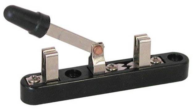
Figure 6-1. A knife-blade switch
Switches have come a long way since they made their first appearances in the 19th century. They are now available in a vast range of styles and types. Some are incredibly tiny, while others are huge. They can be push activated, sliding, or rotary. Some have a so-called toggle handle to operate them, whereas others have a rocker type of operation. Some are designed to be operated solely by a mechanism, rather than by a human being. Still others have built-in lamps of some sort to let the operator know when a circuit is active or a fault has occurred. A whole industry has grown up around the design and production of switches, and many engineers spend their entire careers designing and testing new types of switches and improving on the designs of older types.
A look at the switches section of the website for a major distributor such as Digikey or Mouser will reveal a mind-numbing variety to choose from. In this chapter, we’ll look at some of the more commonly used types and pay special attention to things like physical mounting requirements, connection methods, current ratings, and durability.
Relays are a type of electromechanical switch, and they are discussed separately in Chapter 10. Digital switches are discussed in Chapter 11. In this chapter, we’ll stick to the old-fashioned mechanical types of switches. These devices are all around us in a multitude of types and forms, and they probably will be for a long time to come.
One Switch, Multiple Circuits
In its simplest form, a switch controls one circuit with one contact mechanism by being either open or closed. Figure 6-2 shows a simplified illustration of the internal components of a typical modern single-contact switch. This is a toggle switch, covered in more depth in “Switch Types”.
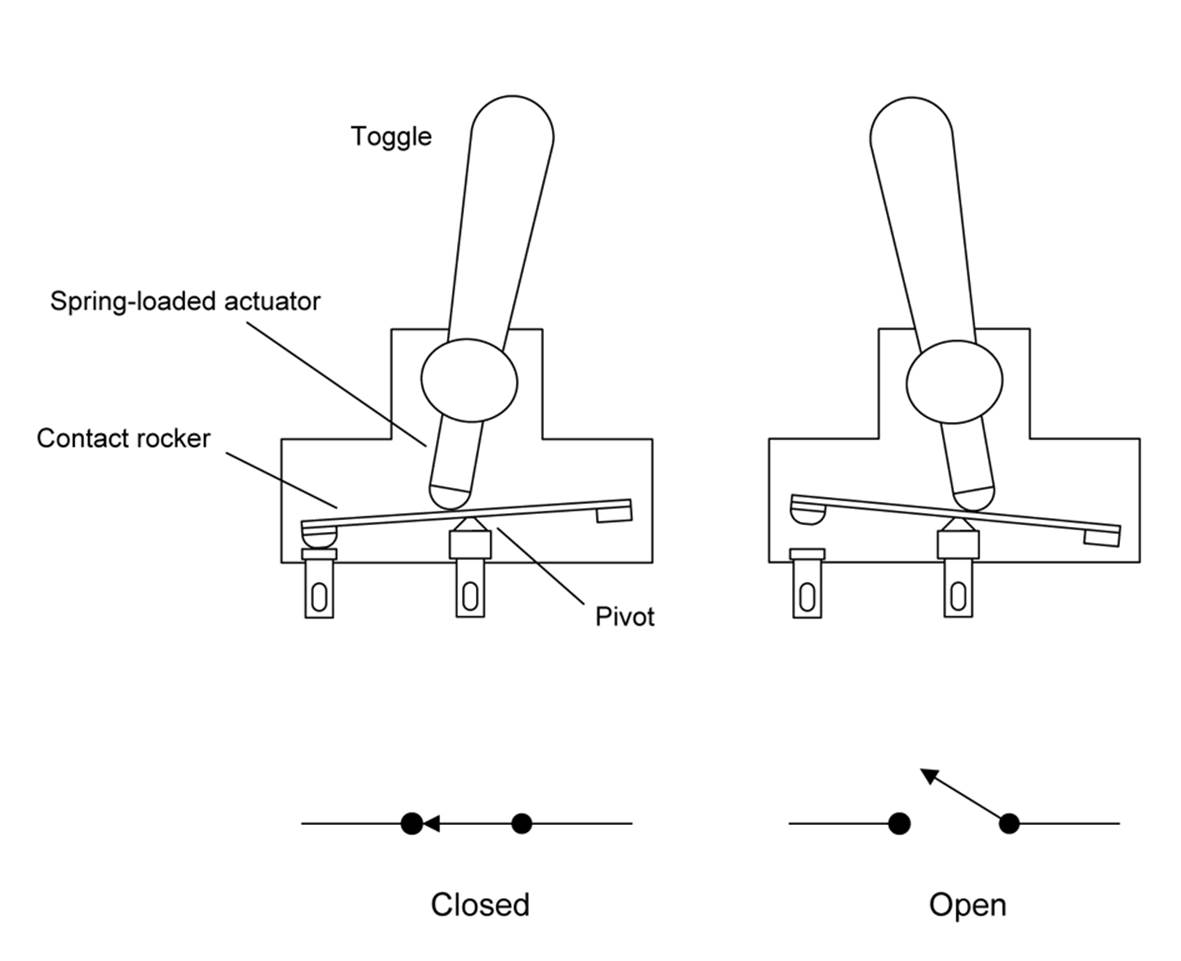
Figure 6-2. Simplified diagram of a toggle switch mechanism
The mechanism is simple, consisting of a contactor that can rock into one position or another. The end of the toggle handle inside the switch is a spring-loaded plunger (the actuator) that pushes the contactor to the desired position and then holds it there. As you can see in Figure 6-2, the contact rocker will either allow current to flow when in the closed position, or it will be open in the opposite position and no current will flow.
This is a common design in switches that incorporate a spring-loaded mechanism of some sort. When the switch is closed, it “snaps” closed and stays in that position. Applying force (via a toggle, rocker, or other means) overcomes the spring tension in the actuator and allows the switch to snap open and remain open. Figure 6-3 shows a typical commercial miniature toggle switch with this type of mechanism.
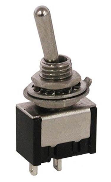
Figure 6-3. A typical miniature toggle switch
Some available switches have two, three, or more internal contacts operating in parallel, thus allowing a single device to control multiple circuits simultaneously. In switch terminology, a single contact is called a pole. Each pole can have one or more positions so that a multi-pole switch can control multiple circuits. The only real limitations to this concept are the physical constraints on the switch and the force required to operate it.
If the switch has only one active position (on or off), it is referred to as a single-throw (ST) type. This is the type of switch illustrated in Figure 6-2 and pictured in Figure 6-3. A switch with two active positions (ON-ON) is called a double-throw (DT) switch.
An ST switch is like a simple gate, whereas a DT type can route current between two different paths, A or B. Some varieties of DT switch have a mechanical “neutral” position in between, which is an ON-OFF-ON type of action.
The contactor (or contact rocker) shown in Figure 6-2 is also called a pole in switch terminology. If the switch has one pole, it is a single-pole (SP) type. If it has two poles, it is referred to as a double-pole (DP) switch. In a DP switch, the poles are mechanically linked and move in unison, allowing the switch to control two different circuits at the same time.
ST, DT, SP, and DP functions can be combined to create SPST, DPST, SPDT, and DPDT switches. For example, the knife-blade switch shown back in Figure 6-1 is an SPDT type. Figure 6-4 shows the schematic representations of the four common switch pole and position arrangements (note that Appendix B covers schematics in detail).
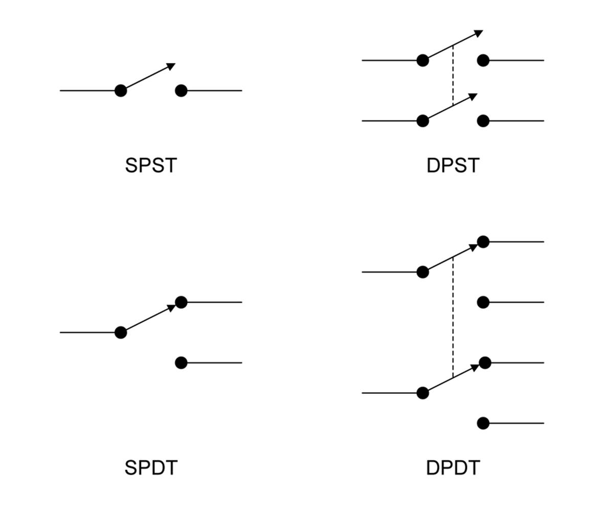
Figure 6-4. Schematic symbols for common SP and DP switch types
Notice that a dashed line is used here to indicate that the poles shown in the symbols are mechanically coupled. A schematic might also use labels, such as S1-A and S1-B, to denote that a switch has more than one pole, or it could use both methods. The current trend is to dispense with the dashed line, but you will likely encounter it in older schematics.
Switch Types
In this section, we’ll look at toggle, rocker, slide, rotary, pushbutton, and snap-action switches. These cover most of the mechanical switch spectrum, and all are really just variations on a theme.
Toggle
The toggle switch is a common type that comes in a variety of styles. Figure 6-5 shows a heavy-duty toggle switch (you’ve already seen a miniature version in Figure 6-3).
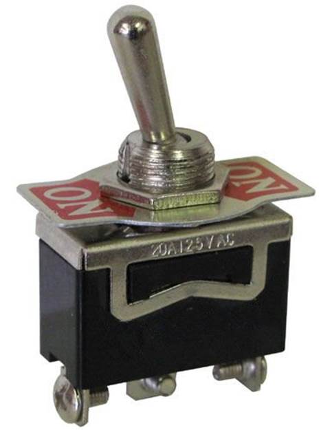
Figure 6-5. A heavy-duty toggle switch
Toggle switches can be even smaller, with a micro form available, as shown in Figure 6-6. These are useful in applications where space is limited, but a toggle switch is still needed.
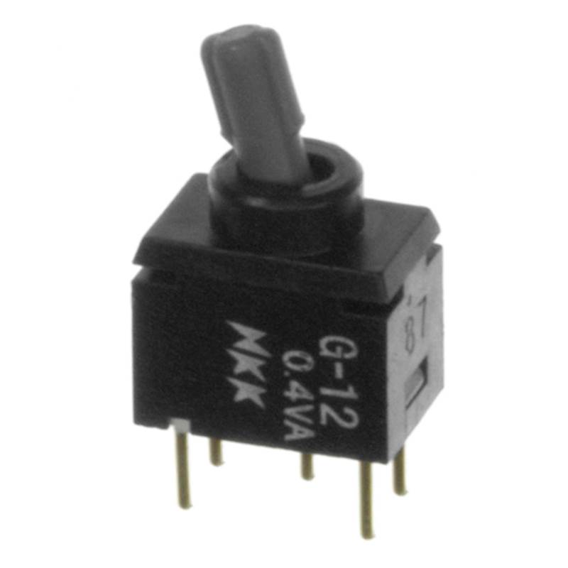
Figure 6-6. A mico-toggle switch
Toggle switches are readily available in SPST, SPDT, DPST, and DPDT forms. They can also be had in three-pole and four-pole versions. It is useful to remember that a SPDT switch with only the common terminal and one position wired is the same as a SPST switch.
Yet another variation is the center-off switch (the ON-OFF-ON type mentioned earlier). In these switches, the internal contacts might be SPDT or DPST, but the toggle handle has three positions. In the center position, the plunger at the end of the toggle actuator will settle into a detent in the middle of the contact rocker, leaving the contact rocker with both ends suspended, and neither of the terminals will be connected.
In some applications, a center OFF with a momentary ON in one of the positions is used for things like testing a subsystem (momentary ON) and enabling the subsystem (normal ON). The manufacturer achieves the momentary action by shaping the contact rocker such that it will not hold the toggle actuator, whereas the regular ON position will. Some designs also incorporate an internal spring to push the actuator back to the center position when it is moved to the momentary position and then released.
Toggle switches might not be the flashiest or most futuristic-looking switches, but they are rugged, easy to use, and ubiquitous. Older styles of common residential light switches are a type of toggle, as are some of the switches found on the front panels of musical instrument amplifiers. The control panels of spacecraft like the Soyuz or the space shuttle contain hundreds of them, and in early computers, toggles switches were one way to enter a program or data into memory. These days, new houses are often wired with a type of rocker switch, which we’ll look at next.
Rocker
A rocker switch employs a plastic or metal piece shaped in a shallow V so that when one end is up, the other is down. In other words, it rocks from one position to another. Internally, the mechanism is identical or similar to that of a toggle switch (or perhaps a slide switch, depending on the manufacturer; see “Slide”). Figure 6-7 shows a typical miniature rocker switch.
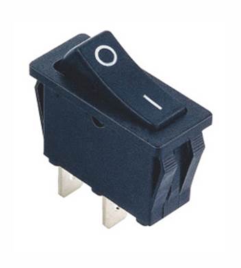
Figure 6-7. A generic SPST miniature rocker switch
All that is really different about a rocker switch is the physical means of changing the internal mechanical state of the switch. Most rocker switches use a pivoted contact rocker similar to that found in a toggle switch. Also note that some rocker switches come with built-in lamps. There are neon, LED, and incandescent bulb types available, and they are commonly encountered in aviation and industrial controls. As with the toggle switches, some older mainframe and minicomputer systems made extensive use of rocker switches to enter data into the machine. Also as with toggle switches, rocker switches can also be found in a center-OFF form, as well as a momentary action in one or both directions.
Slide
Slide switches are a convenient way to select from more than two circuits. A small tab or knob slides in a track to move the pole contactor (or contactors) between positions, and slide switches can have more than one pole. Figure 6-8 shows a typical small slide switch with solder eyelets. This particular switch is designed to be panel-mounted with screws.
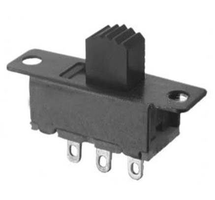
Figure 6-8. A typical small slide switch
Other types of slide switches have pin-like legs for mounting on a PCB, as shown in Figure 6-9. These are useful for situations where a PCB can be used to support the switch, and they look a bit neater than a switch with screws. For a front-panel control, the slide tab protrudes through the panel and the PCB is mounted behind it to support it.
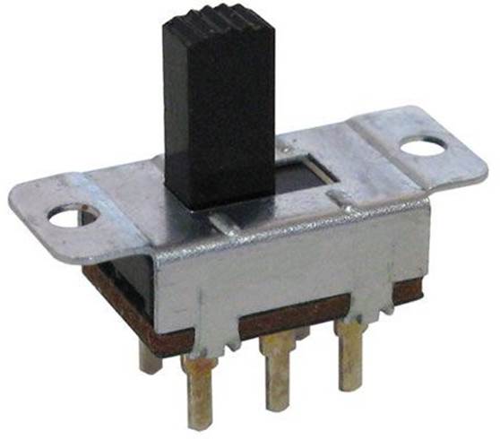
Figure 6-9. PCB-mounted slide switch
Some older radio communications equipment used slide switches with three or more poles to change how the internal circuitry behaves (tuning range, power outputs, etc.). Physically, the pole contactor slides across each of the contact positions while staying in contact with a bar or rail inside the switch. The track the pole contactor moves in usually has small indentations, and a small ball bearing is used to provide some tactile feedback in the form of a “click” or “bump” at each of the contact positions.
Slides switches are available in miniature and micro forms, along with surface-mounted types. PCB mounted versions can be found in both vertical and right-angle designs, and momentary actions are available.
Rotary
Slide and rotary switches are closely related, in that a slide switch is similar to a rotary switch laid out flat with the contacts all in a row instead of a circle. The action of each type is essentially the same. As with slide switches, a rotary switch can have multiple poles. In some older types of test equipment, it wasn’t uncommon to find rotary switches with upward of 10 or even 15 poles per switch.
Rotary switches are readily available and, like every other switch type, come in a variety of sizes and capabilities. Figure 6-10 shows a single-pole rotary switch with six positions. One solder eyelet is the pole, and the rest are the switch-position terminals.
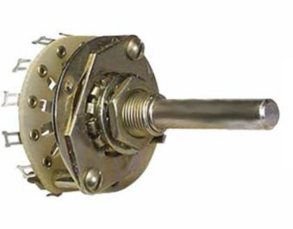
Figure 6-10. Single-pole rotary switch
Rotary switches come in PCB-mount versions, both through-hole and SMT, and there are even some types, like the one shown in Figure 6-11, that require a small screwdriver to operate. These are typically used in places where there might be an occasional need to alter the behavior of a circuit, but not under end-user control. Testing is one situation that comes to mind, or perhaps infrequently changing the behavior of a device.
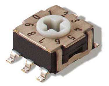
Figure 6-11. Surface-mounted micro rotary switch
Pushbutton
The pushbutton switch is about as ubiquitous as the toggle switch and can be found on everything from a cell phone to the ignition button on late-model cars with electronic key-lock systems. They come in a wide range of styles, some internally illuminated, some not. Figure 6-12 shows a panel-mounted pushbutton switch, and Figure 6-13 shows a PCB version.
Like the other switches we’ve reviewed so far, a pushbutton switch can have more than one pole, although SP and DP types are the most common. The common type of mechanism is a momentary action, but there are some that will mechanically stay in one position or another, like the emergency stop switches on elevators and industrial machines.
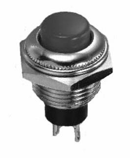
Figure 6-12. Panel-mounted pushbutton switch
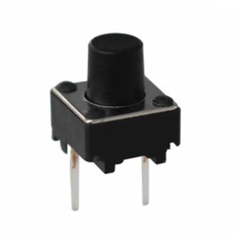
Figure 6-13. PCB-mounted pushbutton switch
Snap-Action
A snap-action switch is typically found in the role of a sensor, rather than something that a human might operate, although there are some varieties that do incorporate a toggle or pushbutton mechanism. These switches are typically used to sense things like physical limits for the moving parts of a machine, the passing of a lobe of a cam, or if a device is resting on a surface or suspended in the air. Figure 6-14 shows a small snap-action switch. Various other types of input mechanisms are available, including rollers, plunge rollers, and pushbuttons.
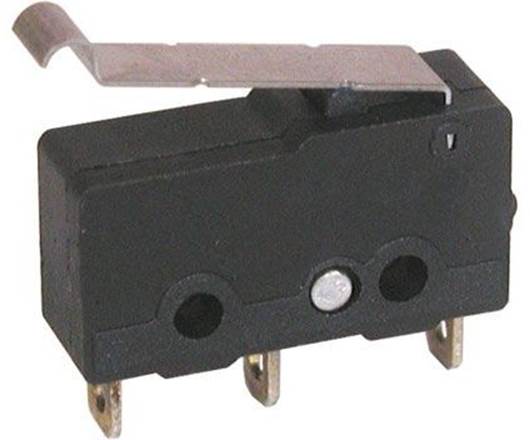
Figure 6-14. Snap-action switch with leaf actuator
A snap-action switch is usually intended for heavy use, and some are sealed to prevent accidental fires or even explosions in hazardous environments (such as might be found in grain elevators). As you might expect, a heavy-duty snap-action switch tends to be both physically large and somewhat expensive, although there are some miniature types available that are popular with the robotics folks.
Slide and Rotary Switch Circuits
As mentioned earlier, slide and rotary switches are similar in terms of functionality, and they differ mainly in their physical form. Electrically, the objective of both types is to select a circuit from multiple choices. Figure 6-15 shows the schematic representation of a four-position double-pole slide switch, similar to Figure 6-9, but with one additional position.
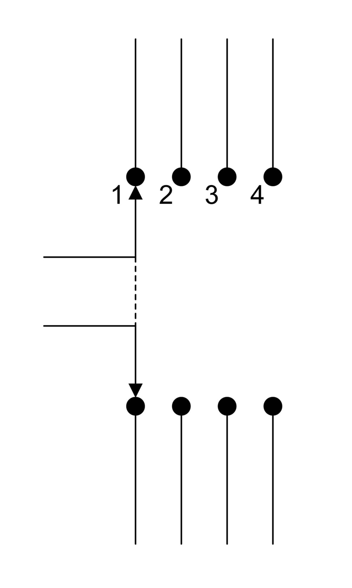
Figure 6-15. Diagram of a four-position slide switch
The schematic for a five-position rotary switch like the one in Figure 6-10 is shown in Figure 6-16.
If a slide or rotary switch has multiple poles, the old-style schematic convention is to show the physical connection between each of the poles with a dashed line, although in some schematics, each pole might be located in different parts of the drawing. More current schematics dispense with the dashed line and just use a numbering scheme (e.g., SW1-A, SW1-B, etc.) to indicate the poles of a single switch assembly.
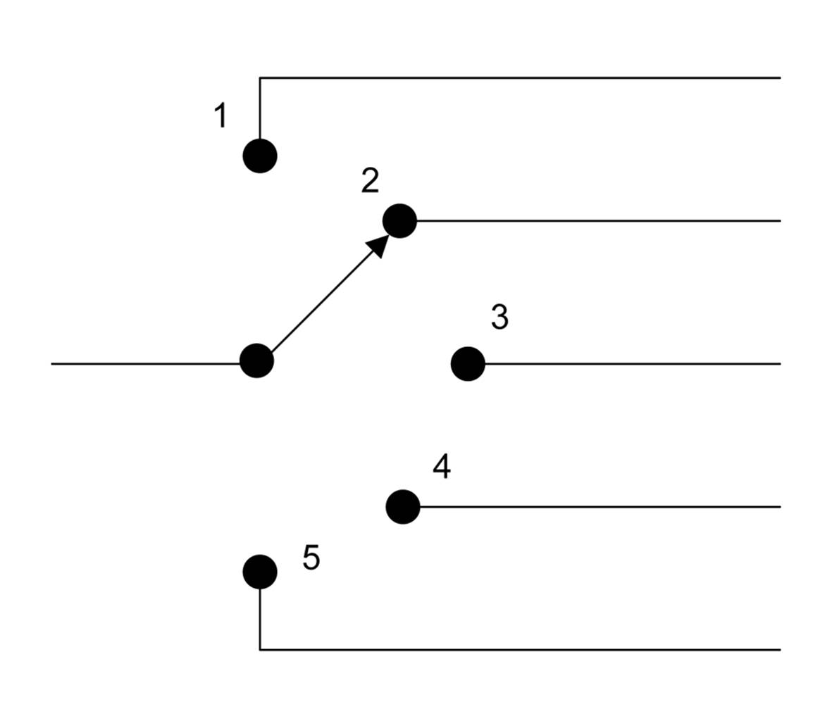
Figure 6-16. Diagram of a five-position rotary switch
Switch Selection Criteria
There are three primary criteria for selecting a switch: what the switch needs to do (electrical characteristics), how it needs to do it (physical form), and where it will be placed (mounting). As often happens in engineering, there are trade-offs that must be made. That really awesome little miniature toggle switch that would be perfect for a project might not be able to handle the current flowing through the circuit it is controlling. Conversely, you might find that the right switch for the voltage and current levels involved will be physically bigger than the rest of the project components combined. The goal is to find the middle ground and pick the best possible switch for the job.
Here are some suggested essential criteria to consider when selecting a switch:
How much voltage will the switch need to handle?
Consider the application and the range of voltages the switch could possibly encounter. Select one that is capable of at least the anticipated maximum value.
How much current will flow through the switch?
Consider how much current the switch will need to handle. Even at low voltage levels, such as 5V DC, there can be considerable current. While internal arcing at low voltage might not be a problem, with a large enough amount of current moving through the switch, its contacts won’t last long. With a significant amount of current, the inherent resistance in the switch’s contacts and metal bus components can be enough to cause the switch to overheat, or even burst into flames. If possible, selecting a switch with twice the capacity of the expected maximum current is a prudent choice.
How many circuits, or contacts, will the switch need to have?
Don’t use a switch with more poles than is really necessary. The more poles a switch has, the more expensive it will be, and the more prone it will be to failure. Less is better.
Should the switch be a toggle, a slider, a rotary type, or some other mechanism?
Don’t let aesthetics be the primary guiding criteria to switch selection. A nifty-looking switch might seem like a good idea, but will it be easy for the user to operate? Will its function be intuitively obvious? Will it be able to endure multiple operations over an extended period of time? Could someone wearing gloves operate the switch? These are consideration that often get a lot of scrutiny in engineering design meetings, and for good reason. Many a gadget has been built with cool space-age controls, only to fail miserably in actual use after a short period of typical user abuse.
Does the switch need to be small? How small?
This criteria is related to the previous consideration, but here the main concern is size versus cost versus available mounting space. Miniature switches that are also rugged aren’t cheap, and they can be a pain to assemble into a design. Select the largest switch you can reasonably use, given the physical constraints of its intended mounting location and the manner in which it is physically connected to the circuit.
Should the switch be a low-force type, or does it need to have a stiff mechanism?
This might seem like an odd topic, but it’s one that is sometimes overlooked in commercial designs, resulting in a product that is difficult (or sometimes even painful!) to use. An extremely stiff slide switch, for example, can leave a user with a sore finger if it must be operated routinely. A rotary switch can be frustrating if it is difficult to turn to a desired position. On the other hand, there are situations where a stiff switch really is the correct choice. The switches on heavy machinery or high-voltage equipment, where an incorrect switch position could result in major problems, are two possible applications. The upshot here is to select a switch that is suitable for the intended application and won’t be easily bumped or jostled into an incorrect position, if that’s a concern.
What are the mounting options? Panel, PCB, or something else?
Toggle, pushbutton, and rotary switches can be mounted in holes drilled into a panel or in some type of chassis. A slide switch will require a rectangular hole, with the length of the rectangle being proportional to the number of switch stop positions. The downside of panel or chassis-mounted switches with soldered leads is that wires are needed to connect the switch to the circuit it is controlling. Switches are also available for PCB mounting, like any other component on the PCB. With a PCB-mounted switch, the wires are eliminated, but now the switch is part of something else, which will have its own mounting requirements. A panel or chassis-mounted switch with PCB terminals can also be used to hold the PCB it is part of.
How rugged should the mounting be?
A switch mounted using a shaft nut or mounting screws will typically be more robust then one soldered onto a PCB, although this depends to a large extent on how well the switch is soldered to the PCB. Some PCB mount switches come with extra metal tabs as part of their body construction. These are intended to be soldered into holes in the PCB to secure the switch. There are protective guards and covers available for toggle switches to help protect them from both impact damage and accidental operation.
Switch Caveats
Being a mechanical device, a switch has certain limitations and behaviors that you should be aware of. With toggle, rocker, pushbutton, and snap-action switches, contact bounce can be a significant concern. If a switch is used to control power to a circuit or a device, this might not be an issue, but when a switch is used to generate or control a signal (such as, say, an input to a microcontroller that is used to count something), contact bounce can become a very big deal.
Contact bounce can be reduced electronically with a filter or a one-shot timer (see Chapter 11 and Appendix A) or, if the switch is connected to a microcontroller, it can be eliminated in software. It is beyond the scope of this book to address software topics, but check out the texts listed inAppendix C for details.
Contact bounce is not the main issue with slide or rotary switches. In a slide or rotary switch, you should be aware that some switches don’t immediately switch from one set of contacts to another. In other words, they can be either shorting or nonshorting. A shorting switch will allow the pole contactor to span two contacts when moving between them. A nonshorting type will have a definite physical gap between the contacts. Why would you want to use a shorting type slide or rotary switch? They are commonly found in circuits that carry audio signals, since the shorting behavior reduces any “pop” that might occur when switching between, say, microphone A and microphone B, or from one filter setting to another. Never use a shorting switch in a circuit that is handling power, as opposed to signals, or evil things might occur, and in general, don’t use a shorting type switch unless there is a definite need for it.
Summary
In this chapter, we’ve looked at some of the various types of switches. You should now have a good idea of what types and styles of switches are available and also have a basic understanding of how they work mechanically. We have reviewed toggle switches, slide switches, rocker switches, pushbutton types, and rotary switch mechanisms. We also took a brief look at snap-action switches, which are common in industrial environments and some robotics applications, but aren’t usually seen in small electronic devices.
The main takeaway from this chapter is to select the switch that meets the needs of the application, unless, of course, you are simply throwing something together to see if it works. Spending some quality time online reviewing the various switches that are available is a worthwhile effort, and a trip to a local electronics outlet can also be informative.
All materials on the site are licensed Creative Commons Attribution-Sharealike 3.0 Unported CC BY-SA 3.0 & GNU Free Documentation License (GFDL)
If you are the copyright holder of any material contained on our site and intend to remove it, please contact our site administrator for approval.
© 2016-2026 All site design rights belong to S.Y.A.