Raspberry Pi Hacks (2014)
Chapter 5. Multimedia Hacks
One of the first things many people do with their Raspberry Pis is to set up an XMBC media center. If that’s where you’d like to start as well, we’ve got you covered ([Hack #54]).
But there’s a lot more you can do in the multimedia realm with this fun little device. Why limit it to being the media server when you can take it on the road and use it for in-car entertainment ([Hack #55])? You can also turn it into a radio ([Hack #49]), play your favorite childhood video games ([Hack #51]), jazz up your next party with a photobooth ([Hack #53]), and more.
Hack 46. Play Video Files
Want to watch a video on your Raspberry Pi? Using the right software will help you get the best performance on playback, even from HD 1080p files!
The Raspberry Pi is not quite the same as a normal computer, but one thing that it can do very well is video decoding. On your Linux laptop, when you play a video file, you are probably decoding that file entirely in software. This works fine, because your laptop CPU is fast enough to do this work in real-time. The Raspberry Pi CPU is not generally fast enough to do this, though, so to make up for it, the Broadcom 2835 system-on-chip graphics processing unit (GPU) includes dedicated hardware to decode (and encode) video files. You can access this hardware through the VideoCore libraries, but most of the video player software commonly used on Linux does not yet have support for those libraries.
Enter omxplayer, a video player specifically made to access the Raspberry PI’s GPU via the VideoCore libraries. It was made by Edgar (gimli) Hucek, and while it is not fancy (it has no GUI), it just works. The maintained source code for omxplayer lives athttps://github.com/popcornmix/omxplayer.
Omxplayer was designed for the Raspbian environment and is much more complicated to build for other platforms. If you want to build for Pidora, you should try the steps documented by Omarr Khattab.
To install omxplayer on Raspbian, you will need to have Git installed and then clone a copy of the source tree into your home directory on the Raspberry Pi:
$ sudo apt-get install git
$ git clone https://github.com/popcornmix/omxplayer
Cloning into 'omxplayer'...
remote: Counting objects: 1065, done.
remote: Compressing objects: 100% (539/539), done.
remote: Total 1065 (delta 730), reused 823 (delta 523)
Receiving objects: 100% (1065/1065), 1.38 MiB | 598 KiB/s, done.
Resolving deltas: 100% (730/730), done.
Because you will need to build it from source, you’ll need to complete some additional build dependencies and system preparations. To simplify the process on Raspbian, just run the included script (./prepare-native-raspbian.sh), which will prepare the OS for building omxplayer:
$ ./prepare-native-raspbian.sh
This will do a lot of things:
§ Patch the makefiles for the Raspbian specific settings.
§ Install dependent packages for building omxplayer.
§ Install gcc 4.7, which is necessary to build omxplayer.
§ Update the Raspberry Pi firmware.
§ Install the latest prebuilt Linux kernel (and modules).
§ Update to the latest videocore libraries and headers.
§ Sync the changes to the SD card.
§ Launch raspi-config to enable you to set the memory_split. If you have an older Raspberry Pi Model B (with only 256 MB of memory), you will need to set the memory_split value to 16; otherwise, the ffmpeg code in omxplayer will not compile. If you have a current Raspberry Pi Model B, the default setting (64) is acceptable as is.
Even with this process, you still have a few things left to do to get it working.
There is (at least as of the time of this writing) one minor bug in Makefile.include that will prevent it from building. To fix it, open Makefile.include with your favorite text editor and add this string to the end of the INCLUDES line (should be the last line in the file):
-I/opt/vc/include/interface/vmcs_host/linux/
Be sure there is a space between this string and any of the already present strings.
Additionally, you will need to configure gcc and g++ 4.7 to be your default compilers. Raspbian uses the alternatives mechanism to allow for multiple versions of the gcc compilers to be installed simultaneously. To switch to gcc 4.7, run:
$ sudo update-alternatives --install /usr/bin/gcc gcc /usr/bin/gcc-4.6 60 --slave /usr/bin/g++ g++ /usr/bin/g++-4.6
$ sudo update-alternatives --install /usr/bin/gcc gcc /usr/bin/gcc-4.7 40 --slave /usr/bin/g++ g++ /usr/bin/g++-4.7
$ sudo update-alternatives --config gcc
At the end of this, the update-alternatives command will prompt you to choose the number for the gcc version that you wish to be the default. Enter the number that corresponds to the entry for gcc 4.7.
Finally, you will need to install the dbus development headers:
$ sudo apt-get install libdbus-1-dev
When this finishes, you will need to add the dbus header include flags to Makefile.include. You can quickly determine what those are by running:
$ pkg-config --cflags dbus-1
At the time of this writing, that command returns:
-I/usr/include/dbus-1.0 -I/usr/lib/arm-linux-gnueabihf/dbus-1.0/include
Add those additional include flags to the end of the INCLUDES line (should be the last line in Makefile.include):
At this point, you will need to reboot the Pi and change back into the omxplayer source directory. From there, you will need to build ffmpeg from source (there is a version of ffmpeg in the Raspbian repositories, but it is too old):
$ cd ~/omxplayer
$ make ffmpeg
In case it was not clear from the earlier comment about allocating most of the Raspberry Pi memory to the OS (and away from the GPU), compiling ffmpeg is a resource-intensive process. It will take a while to complete, but when it does, you will be able to build the rest of omxplayer:
$ cd ~/omxplayer
$ make
$ make dist
To install omxplayer system-wide, go into the omxplayer-dist directory and copy the file tree into the top-level usr/ directory as root:
$ cd omxplayer-dist
$ sudo cp -a usr/* /usr/
There is one last thing you will need to do to use omxplayer. Because omxplayer accesses the videocore directly on the Raspberry Pi, it uses /dev/vchiq. This device node is not normally accessible by non-root users, so if you want to be able to run omxplayeras another user, you’ll need to set up a udev rule to allow users in the video group to access /dev/vchiq:
$ sudo su -
$ echo 'SUBSYSTEM=="vchiq",GROUP="video",MODE="0660"' > /etc/udev/rules.d/10-vchiq-permissions.rules
$ usermod -aGvideo <USERNAME>
Substitute your username (the default user for Raspbian is pi) for <USERNAME> in the usermod command. Then reboot the Raspberry Pi one last time.
You are ready to watch videos with omxplayer now. To watch a video, simply run:
$ omxplayer -o hdmi myvideo.mp4
The -o flag allows you to select the output device. You are probably connected to the HDMI cable for audio and video. If so, you need to specify hdmi as the output device.
There’s no man page for omxplayer, but the options are somewhat documented in the output of omxplayer --help.
To control the video during playback, use control keys. Table 5-1 shows the more common control keys for omxplayer.
Table 5-1. Common omxplayer control keys
|
Key |
Function |
|
< |
Rewind |
|
> |
Fast Forward |
|
s |
Toggle Subtitles |
|
p / space |
Pause |
|
q |
Quit |
|
- |
Volume Down |
|
+ / = |
Volume Up |
For the full list of control keys, see the output of omxplayer -k.
Hack 47. Enable Additional Video Codecs
The Raspberry Pi hardware is capable of decoding audio and video formats directly. It ships with support for the most common formats, but you can unlock more.
One of the powerful features of the Raspberry Pi lies in the BCM2835 system-on-chip’s ability to do fast hardware decoding (and encoding) of video formats. Without this, the Raspberry Pi would have to process video files with software codecs for decoding/encoding, and the Raspberry Pi is not a fast computer in this regard. As a general rule, if you can do it natively with hardware, it will run faster than it would emulated in software.
The BCM2835 system-on-chip is capable of natively decoding most video formats, but it supports only H.264/MPEG-4 video in the stock Raspberry Pi. The reason for this is simple: money. The Raspberry Pi Foundation needed to cut every possible corner to keep the per-unit costs for the Raspberry Pi as low as possible. In order to enable the BCM2835 to support a particular hardware video codec, they would have to pay a per-device license fee. As a result, they could afford only one video codec, so they picked one that they felt would be the best (and most common) codec.
While H.264/MPEG-4 is pretty common, there are a lot of video files that are encoded in MPEG-2. The Raspberry Pi Foundation looked into also enabling that codec by default, but it would have increased the cost of every Raspberry Pi by approximately 10%. They also couldn’t afford a blanket license for the MPEG-2 codec, so they worked out a clever compromise. They set up a store to sell video codec license keys.
For a few dollars, you can purchase a license for either the MPEG-2 or Microsoft’s VC-1 codec. This license will be tied to your Raspberry Pi’s unique CPU serial number. Once you purchase the license, the Raspberry Pi Foundation will send you back a numeric string. To enable the hardware video codec, you need to edit /boot/config.txt and pass that string as the value for the matching codec enablement option. To enable the MPEG-2 hardware codec, add a line like this to /boot/config.txt:
decode_MPG2=0x18675309
To enable the VC-1 hardware codec, add a line like this:
decode_WVC1=0x11235813
You can have multiple keys for multiple Raspberry Pi units (allowing you to swap out an SD card). To add additional keys, simply append them in a comma-separated list, like this:
decode_MPG2=0x18675309,0xdeadbeef,0x11001001
Feel free to try these example “license keys” out if you must, but they’re not real. Sorry. You’ll need to pay the license fee to get working keys for your Raspberry Pi.
VIDEOCORE ACCELERATED VIDEO CODECS
In January, the Raspberry Pi Foundation pushed out a firmware update to add support for several free video codecs, specifically, VP6, VP8, MJPEG, and Ogg Theora. This support differs from the other codecs, because they are not handled completely in hardware, but instead, are accelerated with the videocore libraries. This means they are not as fast as they would be if the BCM2835 system-on-chip was doing all the work in hardware, but they’re much much faster than they would be going through a pure software video decoder. Practically, this means that you can get pretty seamless playback for files in these formats via omxplayer ([Hack #46]) or XBMC ([Hack #54]) without having to do anything special at all.
Hack 48. Build a Pi MusicBox
The Pi MusicBox turns your Raspberry Pi into a controllable music player that supports Spotify, Apple Airplay, and Web Radio.
Say you have a huge library on Spotify (20+ million songs) just waiting for you to play them on your computer. Spotify is great. But how to play these songs on your audio setup? Using a headphones cable? That’s not great with your laptop. Bluetooth? Unreliable.
Enter Pi MusicBox. It turns your Pi into a music player (supporting Spotify, Apple Airplay, and Web Radio), which you can operate from your desktop computer or from your couch using a tablet, smartphone, or laptop. Connect your Raspberry Pi to an audio setup, install the software, and welcome a new way of listening to music!
It can output the sound not only through the headphones jack of the Pi, but also through HDMI and USB, and it supports playing music via WiFi, Last.fm, and from the SD card. The software will detect as much of the configuration as possible at boot, and configure the system automatically. But you have to supply the system with some information.
For this hack, you’ll need a Spotify Premium account and an audio set, either headphones or a set of USB speakers. A monitor or television is not required, but might come in handy.
Getting and Configuring the Software
Download the ready-to-go image from http://www.pimusicbox.com. For this guide, we used Pi MusicBox version 0.4. Newer versions should generally work the same way, though specific options could change.
After downloading the ZIP file, extract it:
$ unzip musicbox0.4.zip
Put the resulting image on your SD card (you’ll need to use at least 1 GB):
$ su -c 'dd bs=4M if=musicbox0.4.img of=/dev/mmcblk0'
$ su -c 'sync'
To make it as easy as possible to configure, you can edit the settings of Pi MusicBox from any file manager, whether you’re using Linux, Mac, or Windows.
In MUSICBOX, you’ll see a folder called config containing a file called settings.ini, which you should open in a text editor. The file is structured like other ini files. All lines starting with a ## are comments, and some configuration lines are also commented out. If you want to use them, remove the ## at the beginning of the line.
You can also edit this file when you boot your Pi and log in (see Getting Your Hands Dirty). The file then is located in /boot/config/.
The most basic configuration file looks like this:
[MusicBox]
SPOTIFY_USERNAME = ‘spotifyusername’
SPOTIFY_PASSWORD = ‘spotifypassword’
These three settings should be enough to run Pi MusicBox:
[MusicBox]
The section name of the configuration file. It has to be there, but you can ignore it.
spotifyusername
The username of your Spotify Premium account (or Facebook login if you use Facebook to connect to Spotify).
spotifypassword
Your own password, of course.
After you edit the basic settings, you can boot Pi MusicBox. You can edit many more settings, but it’s good to try booting with the basic ones first, check to see that it’s all working, then come back later to add the rest.
Note that the Pi MusicBox requires a network connection to operate. It will not start without one. If you use a wired network, all you have to do is plug the network cable in the Pi and it will be configured using DHCP. If you want to use a static address, you need to get into the console and configure it yourself (see Getting Your Hands Dirty).
Connecting through WiFi using a dongle is also supported. If you connect a supported WiFi dongle to your Pi, the MusicBox software should be able to detect and use it instead of a cable connection. Most dongles are supported, but not all. If you buy one, make sure it’s supported by Raspbian, the Linux distribution on which MusicBox is based.
To make WiFi work, you have to fill in the network name (SSID) and your password in the config file. Add these lines to the basic configuration shown previously, or edit the default file supplied with MusicBox:
WIFI_NETWORK = 'mywifinetwork'
WIFI_PASSWORD = 'mypassword'
Substitute mywifinetwork and mypassword with the correct values of your own network. For now, the WiFi on Pi MusicBox supports only WPA(2) encrypted networks configured via DHCP. As with a wired network, if you want to use a static address, WEP encryption, or no encryption, you need to get into the console and configure it yourself (see Getting Your Hands Dirty).
Playing Music
Once you’ve booted the Pi MusicBox, if you have a monitor attached, you will see a message that says:
Now the output of Mopidy (the musicserver) appears. Nothing to worry about (it's shown for if something's wrong), you can log in if you want (the output of Mopidy could continue).
Below that you’ll see some information about your MusicBox setup, such as the active connections. You can start typing a login name (there’s no prompt), but you don’t need to. Pi MusicBox is designed to be operated not from the Pi itself, but from another computer, such as a laptop, desktop, tablet, or smartphone. You can use almost any device with a modern web browser (Chrome 14+, Safari 6+, Firefox 11+, or Internet Explorer 10+) to operate it.
Point your browser to the Pi at http://musicbox.local. Most OS X/iOS and Windows devices will find it immediately. If it doesn’t work, you could try to install Apple Bonjour or iTunes in Windows to make it work. Linux should also work if Avahi or Samba/Winbind is installed. You have to add the http:// part of the address in some browsers, because otherwise, it will try to search for musicbox.local in Google.
If it doesn’t work, or if you use Android (which does not support Bonjour/Avahi/Samba), you have to access MusicBox using the IP address of your Pi. This address is different on every network (e.g., http://192.168.1.5/ or http://10.1.100.2). You can look it up using a network utility (see [Hack #12] for more suggestions) or read it from the screen when Pi MusicBox boots.
Now that you’re connected, it’s time to play some music. The process varies, depending on your music source.
When you access the interface, most things are clear immediately. Your Spotify playlists will appear by default on the first tab. Select one of the playlists to show the tracks it contains. Select the track you want to play, and choose one of the play options in the pop-up menu that appears. Using this pop-up menu, you can either play the song, add it to the queue, or find more tracks from the same album or the same artist. Just play around—literally!
You can also start by searching. Use the third tab at the bottom of the screen to reach the Search functions, where you can look for artists, albums, or songs, as shown in Figure 5-1.
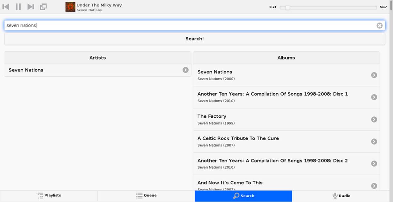
Figure 5-1. The Pi MusicBox Search function
Once you’ve found a song that interests you, click it to play it or add it to your queue with the pop-up menu shown in Figure 5-2.
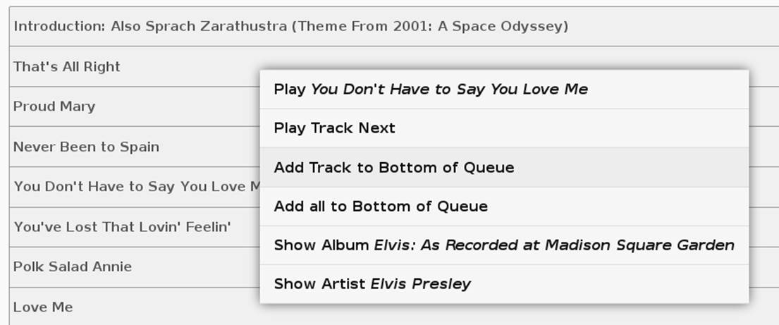
Figure 5-2. Play a song immediately or add it to the queue
The second tab lists all the songs in your queue (see Figure 5-3). You can click them to get a similar menu to the one in Figure 5-2, or you can use it to remove songs from the queue.
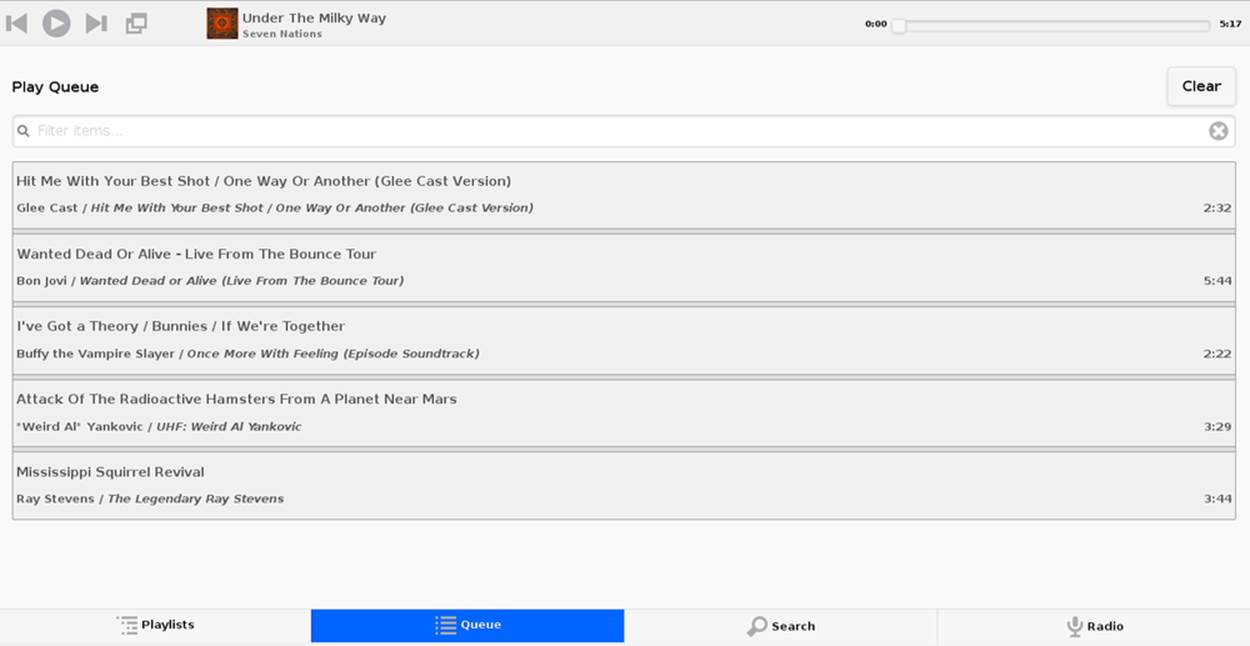
Figure 5-3. A Pi MusicBox queue of songs for the worst (and shortest) party playlist ever
If you would rather play streams from web radio stations, you have to use a stream URL. You cannot use commonly available container files like M3U, XSPF, or PLS (yet). You have to add the real stream. This stream URL is hidden inside the M3U or PLS file. To find this URL, open the container file in a text editor. A PLS file looks like this:
[playlist]
numberofentries=1
File1=http://vprbbc.streamguys.net:8000/vprbbc24.mp3
Title1=BBC World Service
Length1=-1
version=2
The stream URL in this example is http://vprbbc.streamguys.net:8000/vprbbc24.mp3. M3U and XSPF files look different, but the stream URL is always clearly visible.
As you can see in Figure 5-4, several streams are already set up when you first use Pi MusicBox.
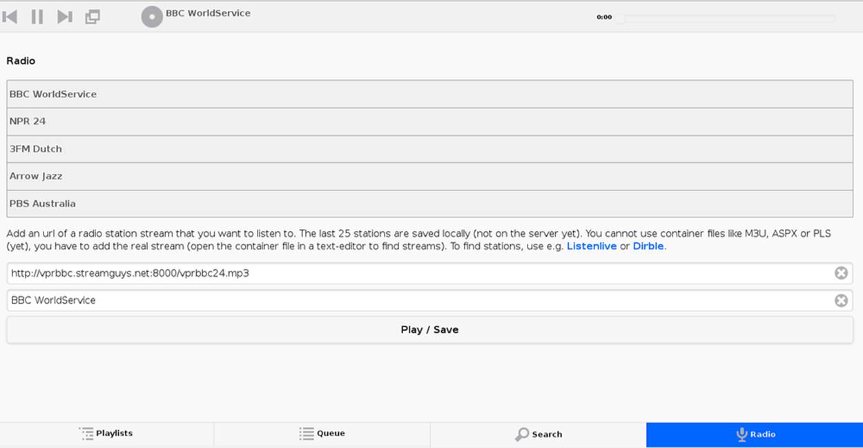
Figure 5-4. Ready-to-go web radio stations in Pi MusicBox
You can find radio stations (PLS and M3U) using services like http://dir.xiph.org/, Listenlive.eu, or Dirble.com. Add the stream URL and the name of the station and press the Play button. The last 25 stations are saved locally using a browser cookie (not on the server yet, so you need to do it on every client you use).
Pi MusicBox also supports Last.fm, which collects the tracks you play so you can discover new music. Go to http://www.last.fm to create an account if you don’t already have one. To let Last.fm collect the tracks you play, fill in the credentials of this service:
LASTFM_USERNAME = 'lastfmuser'
LASTFM_PASSWORD = 'lastfmpassword'
Another service supported by Pi MusicBox is SoundCloud, the service that lets you “hear the world’s sounds.” To configure it, you need a special ID, a token that you can get from http://www.mopidy.com/authenticate. You have to log in with your SoundCloud ID to get the token. This information is not shared with the mopidy.com site. When you log in, you’ll see a token appear on the page. Add this token to the settings.ini file, similar to this:
SOUNDCLOUD_TOKEN = '1-1111-111111'
SOUNDCLOUD_EXPLORE = 'electronic/Ambient, pop/New Wave, rock/Indie'
Replace the example 1-111-111111 with your token. Use the SOUNDCLOUD_EXPLORE configuration to configure the playlists you want to see in the interface.
Multi-room audio
Pi MusicBox supports multi-room audio, meaning you can have multiple Raspberry Pis on your network, even in different rooms. The devices need to have their own names to be accessible. Use this option to give your MusicBox a different name:
NAME = 'Kitchen'
The name you choose should be no than nine alphanumeric characters (no spaces, dots, etc.). After a new boot, the web interface for playing music will be accessible via a new address. Where the default would be http://musicbox.local from devices that support Bojour/Avahi, when you change the name, it becomes http://newname.local. In the previous example, it would be http://kitchen.local/.
It’s not possible to play different music on multiple devices using the same Spotify account at the same time, unless you have multiple accounts. This is a limitation of Spotify.
Music Player Daemon (MPD)
Though the web-based interface is recommended, you can also use native software that supports the Music Player Daemon (MPD) protocol to control Pi MusicBox. Apps and applications are available for all sorts of devices and operating systems. Not all of them work great with MusicBox, though.
For Android, MPDroid is recommended. On OS X, Theremin works (without search). On Linux, you can use the excellent (and wonderfully named) console app ncmpcpp. On a Linux desktop, GMPC and Sonata work well. On iOS, try mPod and mPad. For Windows, clients either don’t work well or are untested.
The Pi can play the music from Spotify in different levels of quality. The better the quality, the more data needs to be downloaded from Spotify (this is called bitrate). Higher quality means a higher bitrate and a bit more use of your Internet connection.
Typical broadband connections should be able to support the highest bitrate easily. If you have a good connection to the Internet, you can set the quality to high, but if your connection is slow or unstable, or if you have usage limits on your connection, you can it lower and use less data. Possible rates are 96 (low, but acceptable quality, FM-like), 160 (default), or 320 (highest quality, CD-like).
Set the bitrate to high like this in the configuration file:
SPOTIFY_BITRATE = 320
Or set the bitrate to low like this:
SPOTIFY_BITRATE = 96
You can install MPDroid from Google Play. (Or if you’d like to try others, consult the MPD Wiki’s list of clients.) When you first start it, you’ll see the settings page. Choose “Default connection settings,” which will take you to a list of options as seen in Figure 5-5.
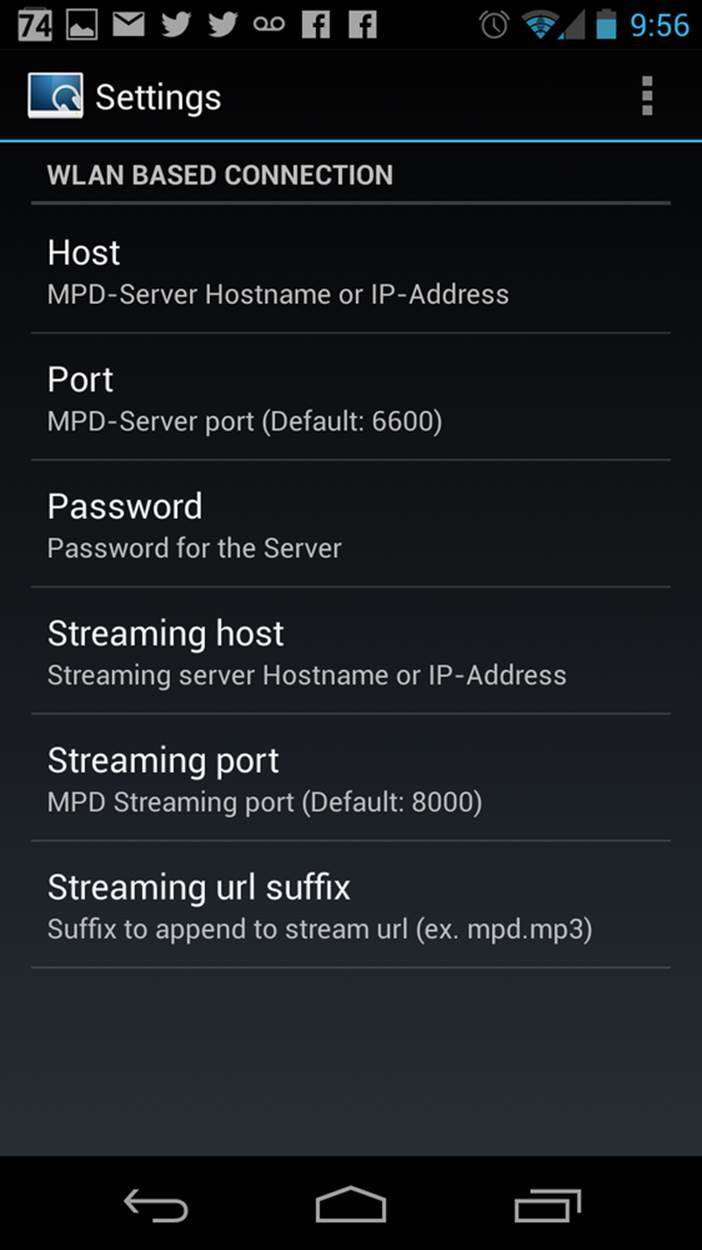
Figure 5-5. MPDroid settings page
Select Host, and enter the IP address of your Pi MusicBox. Then return to the main menu, and you should see your playlist start playing (Figure 5-6).

Figure 5-6. MPDroid playing music
Remember that unless you’ve opened your Pi to the external Internet, you’ll need to connect your phone to WiFi on the same network, or MPDroid won’t work.
Networked music
If you would like to play your own music files, you can do so via a Windows network. To do so, edit the configuration file, so that MusicBox knows where your files are. This address could be a bit cryptic to a first-time user—for example:
NETWORK_MOUNT_ADDRESS = '//192.168.1.5/musicshare'
or:
NETWORK_MOUNT_ADDRESS = '//mynasserver/shared/music'
The first part (//) is the way shares in the Windows network are created. Just add it and forget it. The next part (mynasserver or 192.168.1.5) is the name or IP address of the server that hosts the file. The last part (/musicshare or /shared/music) tells MusicBox which share to mount.
When your server is protected, you need to set the username and password for the Network share using the following configuration lines:
NETWORK_MOUNT_USER = 'username'
NETWORK_MOUNT_PASSWORD = 'password'
MusicBox will not see the files immediately. The music files needs to be scanned at boot, every time you add or remove files. This process can slow down the boot of the MusicBox, so use it with care. MusicBox will scan the files using the following configuration lines:
SCAN_ONCE = 'true'
or:
SCAN_ALWAYS = 'true'
The names speak for themselves. Using SCAN_ONCE, the music files will be scanned only once. Use this if you don’t change the music files often. Use SCAN_ALWAYS if you change your music files a lot. This will enable you to change the files and reboot MusicBox. It will recognize the new files after the boot. But, again, the scanning process can slowdown the booting of MusicBox considerably.
Local music
Pi MusicBox also has an option to store music files on the SD card. This process is a bit more complicated. Since MusicBox is created for a 1 GB or larger SD card, the filesystem is also less than 1 GB. If you put MusicBox on a larger SD card, the rest of the space on the card won’t be used unless you resize the filesystem.
You can do this manually using a partition manager (on Linux, try GParted), or you can let MusicBox try to resize it automatically. If the process fails, you’ll have a nonfunctional MusicBox, but since you should be doing this at the beginning, you can just start over with the installation. If you’ve done a lot of customization, however, you should back up the card first.
Using this line in the settings, Pi MusicBox will automatically resize the filesystem to the maximum size of the SD card:
RESIZE_ONCE = 'true'
Putting music files on the SD card is recommended only on cards larger than 1 GB. MusicBox needs the 1 GB for caching and other storage. After resizing an SD card with more storage, you can put your own music files on the Pi using either the Windows network or by mounting the root filesystem of the card on a Linux computer and copying the files. Leave at least 200 MB of free space on the device.
To use the Windows network, you have to have the workgroup name of the network set to the default name, WORKGROUP. If you want another name, you have to change it by hand in /etc/samba/smb.conf (see Getting Your Hands Dirty). Remember to let MusicBox scan the files at boot (see Networked music).
Sound Configuration
By default, Pi MusicBox will send the sound to the analog headphone output on the Pi. This sound is good enough, but due to hardware constraints, not always great. If you want to have better sound, use the HDMI to connect the Pi to an amplifier, or connect a USB sound card (also called USB Digital Audio Converter/DAC), USB speakers, or USB headphones. MusicBox supports almost all types of USB speakers, headphones, and DACs, but if you buy one, make sure it’s Linux compatible. DACs with digital outputs are also available in many web stores.
When booting, Pi MusicBox will autodetect what is connected to the device and configure it accordingly. If you connect multiple devices, USB will be selected first as a sound output, HDMI after that, and lastly the analog output of the Pi itself. You can override this in the configuration file using the following line:
OUTPUT = 'analog'
If you include this, the default output will be the analog headphones jack of the Pi, even if you connected using an USB device or an HDMI cable. The options are analog, hdmi, usb.
Security
Pi MusicBox is not totally secure and is intended to run only in the cozy environment of your local network, not outside a firewall. The heart of MusicBox is not protected enough to do that. Also, your WiFi and Spotify passwords are stored in plain text on the SD card. This might be fixed in the future.
For more security, change the default password by setting this line (where mypass is your new password):
MUSICBOX_PASSWORD = 'mypass'
This will change the passwords of both the user musicbox and the user root. The password will be removed from the configuration file after it’s updated.
If you want, to change the root password to something else for more security, use this line:
ROOT_PASSWORD = 'mypass'
Getting Your Hands Dirty
If you’d like to dig a bit, there are plenty more options to explore in Pi MusicBox. For the following options, you have to log into the box on the console, or via SSH (see [Hack #12]).
To log in remotely via SSH, you will need to enable the SSH service. Do that by adding this line to your configuration file:
SSH_ENABLED = ‘true’
Reboot. After that, you can connect to MusicBox via SSH.
Mopidy
The main ingredient of MusicBox is Mopidy, an open source music server developed by people from all over the world. By default, Pi MusicBox is set up using the best working extensions, but you can extend it to play music from other sources, such as SoundCloud, Google Music, and Beets Music.
Adding these extensions is beyond the scope of this hack, but you can find additional resources and documentation at Mopidy’s website and reach the developers on the Mopidy mailing list or via IRC on the #mopidy channel on Freenode.
rc.local
The /etc/rc.local file is another important piece of Pi MusicBox. It’s a shell script where the sound hardware is set up and the configuration is done. For example, the configuration file of Mopidy is created from rc.local. Edit this file is you want to add, change, or remove features.
Working at Midnight
For Linux novices, a nice utility called Midnight Commander could be useful for browsing the filesystem and editing files. It works like the age-old DOS-utility Norton Commander and it’s included in MusicBox. Start it using the command mc.
Static network
To use MusicBox in a network with static IP addresses, you have to edit /etc/network/interfaces. The lines that configure the wired network look like this:
allow-hotplug eth0
iface eth0 inet dhcp
For a static wired network, you should change it to something like this:
iface eth0 inet static
address 192.168.1.5
netmask 255.255.255.0
gateway 192.168.1.1
Change the IP addresses as applicable for your network. For more about finding and setting your IP address, see [Hack #13].
Updating
When a new version of MusicBox is released, the only way to update it is to do a new installation. Note that if you update the kernel or other packages on the system manually without a new MusicBox installation, it could eventually break things, so a fresh installation is preferred.
—Wouter van Wijk
Hack 49. Turn Your Pi into a Radio
Sure, it’s easy to play an entire library of music files from your Raspberry Pi. But how about using the Pi itself (which doesn’t have any sort of built-in radio transmitter) as a radio?
The PiFM project, created by Oliver Mattos and Oskar Weigl, was designed to turn your Raspberry Pi into a radio. By switching a GPIO pin from on to off at a high frequency, you’ll build yourself a makeshift Rapberry Pi FM transmitter.
To get started, download the PiFM files from http://www.icrobotics.co.uk/wiki/images/c/c3/Pifm.tar.gz to your Raspberry Pi and extract the tarball in the Pi’s home folder. You’ll have four files there:
§ sound.wav
§ PiFm.py
§ pifm.c
§ pifm
Tune a radio to 103.3 FM and put it near your Pi. Then open a terminal and enter:
$ sudo python
>> import PiFM
>> PiFm.play_sound("sound.wav")
If you want to play your own sound, convert it to WAV format (16 bit mono, 22 Khz is best) and put it in your home directory.
This will work only with the radio next to the Raspberry Pi. To get a little more range, you can connect any 50 cm wire to GPIO4 to act as an antenna. Pointing it straight up works well and should get you around 50 m of range.
You might need a license to transmit radio in some countries, so if you’re unsure, it is best to leave the antenna disconnected. It will still work, but with a very short range.
Compile the code for pifm.c using the following command:
$ gcc -lm -std=c99 pifm.c -o mypifm
To broadcast your WAV file, just run:
$ ./mypifm myaudio.wav
How It Works
FM stands for frequency modulation, which is how it sends sounds over the air. Frequency modulation works by having a signal (called a carrier signal) that regularly changes from positive to negative and back again very quickly (in the case of the PiFM radio, it changes and changes back again 103.3 million times every second!). When you vary speed of this change to be just a bit faster or slower, the radio on the other end can detect the changing speed and makes sound based on how it changes.
But how do you make the Raspberry Pi change something so quickly and accurately? The Pi has an on-board clock manager that can accurately produce any clock frequency you want by dividing the system processor clock (which is normally around 500 Mhz) down to any other rate you want. To tell it what to do, you set a register (a special piece of memory) to a number saying what you want the system clock divided by to make the FM radio clock. For example:
§ System Clock = 500 Mhz
§ Divider Register = 5.000
§ FM radio clock frequency = 500/5 = 100 Mhz
This divider can be a fractional number and adjusted up and down by tiny bits to make your sound.
Alas, it turns out that to keep your sound playing smoothly, you need to regularly adjust the rate, and the Raspberry Pi isn’t very good at that. The Pi can run more than one program at a time, but it has only one processor. It does this by quickly switching between running programs (multitasking). This normally works well, but in this case, if another program is running when the clock rate needs adjusting, there will be a glitch in the sound.
To combat this problem, you can use the Direct Memory Access (DMA) controller. You can give the DMA controller a list of things to do (e.g., what rate to adjust the sound to at each point in time), and then it does it in the background, even if the main processor is busy running other programs. The PiFM program just makes a list of things for the DMA controller to tell the clock generator to do and then gets it going.
Accessing Hardware
The Python library calls a C program (provided both precompiled and in source form). The C program maps the peripheral bus (0x20000000) in physical memory into virtual address space using /dev/mem and mmap. To do this, it needs root access, hence the sudo.
Next, it sets the clock generator module to enabled and sets it to output on GPIO4 (no other accessible pins can be used). It also sets the frequency to 103.3 Mhz (provided from PLLD@500Mhz, divided by 5), which provides a carrier. At this point, radios will stop making a “fuzz” noise and become silent.
Modulation is done by adjusting the frequency using the fractional divider between 103.325 Mhz and 102.275 Mhz, which makes the audio signal. The fractional divider doesn’t have enough resolution to produce more than ~6 bit audio, but since the Pi is fast, you can do PWM to provide about 10 additional bits, giving a total resolution of 16 bits, matching the audio input.
Fun with FM
Here are some ideas of things you might be able to try with PiFm:
Make a repeated playlist (easy)
A simple loop in Python calling play_sound on different sound files should let you play an entire list of files one at a time.
Make a “mystery sound” game (medium)
Play a sound, and the player must guess which household object makes the same sound. They can take their radio round the house to try to find a matching sound.
Make a Morse code program (medium)
If you make a sound file for “dot,” another for “dash,” and a third as a “gap,” you should be able to play them in the right order to send Morse code.
Make a wireless network (hard)
As an extension of the Morse code idea, see if you can send any information (for example, an image file) via noises on the radio, and make a decoder program on your computer that can recognize the noises through a microphone and convert it to a file again. You now have a crude wireless network link and radio-modem that you have made entirely yourself!
—Oliver Mattos and Oskar Weigl
Hack 50. Control the Pi via Touchscreen
While the Raspberry Pi has native hardware support for two types of video output (HDMI and composite video), there are times where it would be helpful to be able to use it with a touchscreen monitor, such as those used for both display and input in tablet computers.
The Raspberry Pi Model B contains a Display Serial Interface (DSI) connector, which is a 15-way, flat flex connector labeled S2 next to the Raspberry Pi logo on the board. DSI is sometimes used to connect touchscreens in small-form-factor devices such as smartphones. Sadly, adding a touchscreen to your Pi is not as simple as disassembling an abandoned smartphone and reconnecting the screen to the DSI connector.
The GPU firmware that enables the native video output needs code to explicitly support any device connected to the DSI port. Since this firmware is not open source, it is not currently possible to add support for any DSI-connected screens, nor are there any known devices that the GPU firmware supports on the DSI connector. It is widely expected that, at some point, the Raspberry Pi Foundation will release official peripherals that can connect to the DSI connector, which will make this a much simpler task (assuming that one of those peripherals is a touchscreen). Until that point, however, we’ll just have to hack around it.
Choosing a Touchscreen
The first step is to figure out which touchscreen to connect to the Raspberry Pi. There are quite a few touchscreen devices on the market, but the majority of them are extremely expensive, and the Linux support for them is haphazard at best. We chose the Mimo 720 touchscreen because it is small (7” x 5.25” x 1”), light (less than a pound), USB-driven, mountable with a bracket, and relatively inexpensive (MSRP $199 USD, but it is regularly on sale around $129).
There is at least one drawback to this device. It uses DisplayLink, a technology that allows for an additional monitor and graphics device to be connected via USB. Unfortunately, this means that the Mimo 720 is not connected to or using the Raspberry Pi GPU. The result is that it is not possible to use it as a VideoCore output device, and it is not powerful enough to drive anything needing high-quality video performance or acceleration on its own.
So, while it might seem perfect to use in a car seat-back multimedia player hack, we would not recommend it for that use case. There are, however, plenty of other cases where it’s still a handy solution!
The Mimo 720 is technically two devices in one unit: an 800 x 480 LCD DisplayLink monitor and an e2i Technology, Inc. USB touchpanel. Linux detects these devices separately, so it is important for your Raspberry Pi Linux kernel to support for both of them.
Installing and Enabling Drivers
You can make the Mimo 720 available as a monitor to Linux via two kernel drivers, either the USB Display Link Framebuffer Driver (CONFIG_FB_UDL in Kconfig-speak, udlfb.ko as a module) or the USB Display Link Kernel Mode Setting (KMS) driver(CONFIG_DRM_UDL in Kconfig-speak, udl.ko as a module). The UDL Kernel Mode Setting driver does not work as well for this use as the UDL Framebuffer Driver. The KMS driver is likely to eventually be the better choice, but in the interim, the Framebuffer Driver works great for our hacking needs.
The e2i Technology touchpanel portion of the device is driven by the USB Touchscreen Driver (CONFIG_TOUCHSCREEN_USB_COMPOSITE in Kconfig-speak, usbtouchscreen.ko as a module).
Neither the USB Touchscreen Driver nor the UDL Framebuffer Driver is enabled by default in the prebuilt kernels provided by the Raspberry Pi Foundation, and thus, almost never present in Raspberry Pi Linux distribution images, but this is easily remedied with a custom kernel, which you can build from source with the instructions in Install a New Kernel.
When you build your custom kernel for this hack, you will need to be sure that you configure it so that these additional drivers are also built. As a reminder, you can configure which drivers and options to build using make menuconfig.
To enable the framebuffer driver, go into the Device Drivers menu and select “Graphics support” → “Support for frame buffer devices.” At this screen, you need to enable “Displaylink USB Framebuffer support.” Since you will want to use this driver as a module, hit the M key when that item is highlighted in the TUI. When successful, your screen should look something like Figure 5-7.
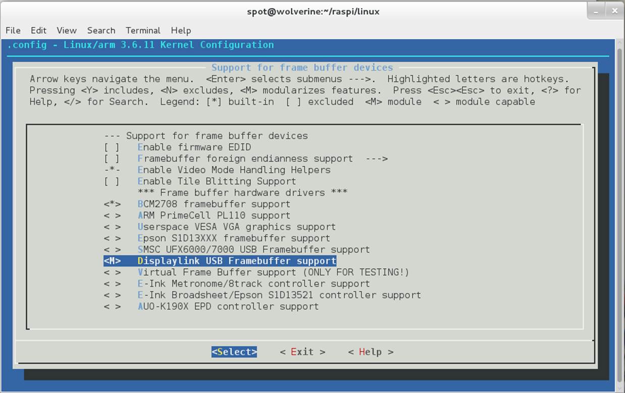
Figure 5-7. Configuring Displaylink USB Framebuffer support as a module
Next, you need to enable USB touchscreen support. Exit to the Device Drivers menu (right arrow to Exit, then Enter). From there, go into the “Input device support” menu. You need to enable the “Touchscreens” option on this page (by hitting the spacebar when “Touchscreens” is highlighted), then press Enter to go into the Touchscreens menu.
In the Touchscreens menu, highlight the “USB Touchscreen Driver” option and press M to enable it as a module. By default, this enables all of the supported USB Touchscreens, but you should still scroll down and make sure that the “e2i Touchscreen controller (e.g., From Mimo 740)” option is enabled. You can confirm that is enabled by making sure that it has an asterisk beside it, as shown in Figure 5-8.
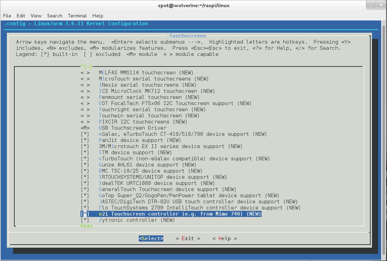
Figure 5-8. e2i Touchscreen controller driver enabled
Once your kernel and modules are rebuilt, simply install them into the Raspberry Pi Linux distribution image. Reboot your Raspberry Pi with the Mimo 720 connected.
On the Mimo 720, the screen will cycle through several colors and patterns as the Raspberry Pi boots. This is the Mimo 720 initializing the frame buffer, and it means that the Mimo 720 works properly. At this point, it will stop at a green screen, which is fine, because you have not yet configured the Linux userspace to run the display.
Within the Raspberry Pi Linux instance, you should see kernel messages like this in the output of dmesg:
udlfb: DisplayLink MIMO - serial #101234567
udlfb: DisplayLink USB device /dev/fb1 attached. 800x480 resolution. Using 1504K framebuffer memory
There are a couple ways you can get this information from your Raspberry Pi:
§ SSH into the Raspberry Pi (see [Hack #12]).
§ Connect a monitor to the HDMI or composite video.
Later, you’re going to reconfigure X to run the main display to the Mimo 720, but for now, the graphical X11 display should still be running on the directly connected monitor.
LINUX DISTRIBUTIONS WITHOUT XORG/X11
OpenELEC makes a build of their XBMC-based Linux OS for the Raspberry Pi, but it does not use Xorg. Because OpenELEC relies entirely on the VideoCore output devices, this particular hack will not work on that distribution, unless you rebuild it entirely from source and enable Xorg support. You’ll have the same problem if you try to use RaspBMC with this hack.
In the dmesg output, you’re looking for the line that tells you which frame buffer device the Linux kernel has assigned to the Mimo 720. In the current example, the device is /dev/fb1. It is probably /dev/fb1 for you as well, unless you have other devices plugged into the Raspberry Pi that show up to the Linux kernel as frame buffers. Just make a note of this device name, as you will need it to write your Xorg configuration file later.
For the touch panel, look for messages like this in the output of dmesg:
input: e2i Technology, Inc. USB Touchpanel as /devices/platform/bcm2708_usb/usb1/1-1/1-1.3/1-1.3.1/1-1.3.1.3/1-1. 3.1.3:1.0/input/input2
usbcore: registered new interface driver usbtouchscreen
These messages mean that the usbtouchscreen driver has been loaded and the e2i Technology USB Touchpanel in the Mimo 720 has been detected.
Now, look in the /dev/input/by-id/ directory. You should see a filename that looks something like:
/dev/input/by-id/usb-e2i_Technology__Inc._USB_Touchpanel_L000000000-event-if00
Take a note of this filename, which you’ll use to identify your touch panel device in the Xorg configuration file. You use this ID instead of using a /dev/input/event* device, because the ordering of those devices can (and does) change when you add things like USB mice and keyboards to the bus. Using the touchscreen’s unique device identifier ensures that you always end up with a working X session.
Xorg Configuration
At this point, it is time to start writing your Xorg configuration file. Modern Linux distributions usually autodetect a working Xorg configuration for the present hardware, but in the case of the Raspberry Pi, it will result in a working X session for the GPU, not the Mimo 720. By making your own Xorg configuration file, you’ll be overriding the autodetection and telling the Raspberry Pi Linux distribution to use the Mimo 720 as the primary graphical display and input device. You can still plug in a USB keyboard and mouse, and those will be auto-detected and used in addition to the Mimo 720 touchscreen as input sources.
Create a new file in your home directory called xorg.conf.mimo and open it in your favorite text editor. (If you don’t care about the inner workings here, you can just download our xorg.conf.mimo from the book’s GitHub repository.)
Your Xorg cofiguration file needs five sections: Device, Monitor, Screen, ServerLayout, and InputDevice:
Section "Device"
Identifier "DisplayLinkDevice"
driver "fbdev"
Option "fbdev" "/dev/fb1"
Option "ShadowFB" "off"
EndSection
This defines a video device named DisplayLinkDevice that uses the fbdev driver across the Mimo’s framebuffer device (/dev/fb1). If your framebuffer device is different, adjust it accordingly.
We also disable the ShadowFB feature. ShadowFB causes the fbdev driver to force the CPU to do each drawing operation first into a shadow frame buffer in system virtual memory and then copy the result into video memory. While this behavior is good for most cases, for our DisplayLink device, you need the CPU to draw directly into video memory:
Section "Monitor"
Identifier "monitor"
Option "DPMS"
EndSection
This section defines a Monitor device, which we have uncreatively named monitor. The only other setting here is to enable Display Power Management Signaling (DPMS), which allows power saving behaviour of the touchscreen when you are not using your Raspberry Pi:
Section "Screen"
Identifier "screen"
Device "DisplayLinkDevice"
Monitor "monitor"
EndSection
The third section defines a Screen device that ties our DisplayLinkDevice video device to our monitor device. This is how Xorg works; it draws to a screen device. Xorg supports multiple devices, including multiple screen devices, but for this hack, we’re keeping it simple:
Section "ServerLayout"
Identifier "default"
Screen 0 "screen" 0 0
InputDevice "touchscreen" "CorePointer"
Option "BlankTime" "0"
Option "StandbyTime" "0"
Option "SuspendTime" "0"
Option "OffTime" "0"
EndSection
The ServerLayout section tells Xorg how to layout any screens that you wish to use. This is simple, because you have only one screen device, so just put it in position 0,0 (the numbers correspond to a horizontal and vertical ordering, where 0 is the first position).
You’ll also tell it that, for your ServerLayout, you want to use the touchscreen input device as your mouse device. By passing it as CorePointer, it tells Xorg to use it as the default mouse device. The other options are for the DPMS timeout settings:
BlankTime
The time in minutes to let the screensaver (if any) run before blanking the screen
StandbyTime and SuspendTime
Define the inactivity period (in minutes) before going into standby and suspend mode, respectively
OffTime
Defines the inactivity period before turning the monitor device off entirely
In this example config, these options are all set to 0, which effectively disables power saving on the device, but you should customize them for your needs.
When setting these, you should stagger them out, in the order presented, so that your monitor device goes blank, then to standby, then to suspend, then turns off entirely. If you do not want your monitor to go into one of those states (or it does not support that state), you can always disable it by passing a 0 value to it:
Section "InputDevice"
Identifier "touchscreen"
Driver "evdev"
Option "Device" "/dev/input/by-id/usb-e2i_Technology__Inc._USB_Touchpanel_L000000000-event-if00"
Option "DeviceName" "touchscreen"
Option "ReportingMode" "Raw"
Option "SendCoreEvents" "On"
Option "Calibration" "449 31910 31857 988"
EndSection
The last section defines the input device for the touchscreen component of the Mimo. The touchscreen device uses the evdev driver, pointing to the e2i input device node identified earlier:
/dev/input/by-id/usb-e2i_Technology__Inc._USB_Touchpanel_L000000000-event-if00
Continuing our less-than-creative naming scheme, it is named touchscreen. We need to have the Mimo touchscreen in Raw reporting mode to work properly, and since we are using it as the main input pointer, we want it to have the SendCoreEvents option enabled.
The last option is a calibration option, which is how the Mimo touchscreen knows how to properly report touch events. The calibration values should be correct for your device, but if they are not, you may need to determine them for yourself. There are a few ways to do this, but the tool that exists for most of the Linux distributions is called evtest. To install it on Pidora, run:
$ su -c 'yum install evtest -y'
Or on Raspbian/Occidentalis:
$ sudo apt-get install evtest
evtest is intended as a debugging tool, to see all of the input that is being generated from an evdev-compatible input device. For calibration purposes, we need to know the minimum and maximum values being reported along the X and Y axes of the touchscreen. Run evtest on the Mimo touchscreen device node:
$ sudo evtest /dev/input/by-id/usb-e2i_Technology__Inc._USB_Touchpanel_L000000000-event-if00
Using the Touchscreen
Now, every time you touch the screen, evtest will output debugging information about the event. For example, when you touch near the center of the screen, it generates an event that looks like this:
Event: time 1378951053.759441, type 1 (EV_KEY), code 330 (BTN_TOUCH), value 1
Event: time 1378951053.759452, type 3 (EV_ABS), code 0 (ABS_X), value 17165
Event: time 1378951053.759456, type 3 (EV_ABS), code 1 (ABS_Y), value 17217
Event: time 1378951053.759460, -------------- SYN_REPORT ------------
Event: time 1378951053.766434, type 3 (EV_ABS), code 0 (ABS_X), value 17191
Event: time 1378951053.766442, type 3 (EV_ABS), code 1 (ABS_Y), value 17259
Event: time 1378951053.766446, -------------- SYN_REPORT ------------
Event: time 1378951053.773442, type 3 (EV_ABS), code 0 (ABS_X), value 17208
Event: time 1378951053.773452, type 3 (EV_ABS), code 1 (ABS_Y), value 17422
Event: time 1378951053.773456, -------------- SYN_REPORT ------------
Event: time 1378951053.826439, type 1 (EV_KEY), code 330 (BTN_TOUCH), value 0
Event: time 1378951053.826456, -------------- SYN_REPORT ------------
This is a single touch (BTN_TOUCH), but you can see it gets three distinct X (ABS_X) and Y (ABS_Y) measurements. To determine the minimum and maximum X and Y calibration values, you will need to touch the upper-left, upper-right, lower-left, and lower-right corners of the screen (as close to the edge as you can). Then, write down the smallest and largest values for ABS_X and ABS_Y that appear in the evtest output. These make up the values that go into your xorg config file, with this option syntax:
Option "Calibration" "<MIN_X> <MAX_X> <MIN_Y> <MAX_Y>"
Substitute in your discovered values for <MIN_X>, <MAX_X>, <MIN_Y>, and <MAX_Y>.
With your xorg.conf.mimo complete, you can now make the Mimo touchscreen into your primary device by copying it to /etc/X11/xorg.conf as root:
$ sudo cp -a xorg.conf.mimo /etc/X11/xorg.conf
When you reboot (assuming that your Linux instance is configured to boot into a graphical mode), you should see your desktop display out to your Mimo touchscreen.
Keep in mind that if you have something connected to the “normal” video output of the Raspberry Pi (e.g., HDMI), you will still see the Linux kernel and boot messages go to that device, because the DisplayLink device is not the main target for that output. Also, because it is not using the VideoCore GPU at all, you will not be able to playback videos using the hardware video codecs, and they will be slow.
Hack 51. Emulate Classic Video Game Consoles
Relive the golden era of home video gaming by letting your Raspberry Pi pretend to be the gaming systems of yesteryear. Hey, you kids, get off our lawn. We’re hacking here!
We both have fond memories of the original Nintendo Entertainment System (NES). (For Tom, it was his first dedicated gaming console. Ruth was still playing with an Atari 2600 and stuck with whatever could be found on 5.25-inch floppies.) Now, although we both have kids who think of video games as something much more complicated than Duck Hunt could have dreamed to be, those old 8-bit (and later, 16-bit) games still have a lot of play left in them.
It’s not surprising to see the retro trend in a lot of new independent video games, but what about going straight to the source? Those old games from the 1980s and 1990s were good enough for us then. We’re certainly not too good for them now. You could spend a lot of money buying a working system and all of your old games on eBay, but let’s assume for a moment that you’re not independently wealthy. Your Raspberry Pi can emulate most of these old gaming consoles for you!
The original video game consoles were good for their time, but by today’s standards, they’re nothing but slow and weak. The NES had a 1.79 MHz CPU (that’s an M, not a G), with 2 KiB of onboard memory. Today, most of these hardware consoles have been fully reverse-engineered, and pure software implementations have been written that can emulate them almost perfectly.
All that’s left to worry about is the games. Even if you still have the media lying around, your Raspberry Pi didn’t arrive with any slots designed for those old game cartridges and discs. Instead, those software emulators are written to read ROM files, which are imaged copies of the games, taken from their original media and saved to a file.
Downloading the ROM files from the Internet for the games that you want to play is the simplest way to get started; however, its legality is questionable in a lot of jurisdictions. There are other alternatives, such as the Retrode gaming adapter, which is a USB device that has native slots for Sega Genesis and Super Nintendo (SNES) games, as well as native connectors for the controllers of both systems.
This hack assumes that you have ROM image files for your games. Depending on where you are, ROMs may have some legal issues. For the purposes of this hack, we will simply assume that you possess legal ROMs.
As for controllers, Linux supports almost any USB joystick that you can find. For the full nostalgia experience, you can purchase original gaming controllers converted to use USB connectors and USB connectors that will provide a native port for the original controller.
USING AN NES/SNES CONTROLLER THROUGH THE GPIO
It is possible to connect an NES or SNES controller directly through the Raspberry Pi GPIO, but you’ll need to build and use a RetroPie GPIO Adapter. There is a complete writeup (with hardware specifications, schematics, and software) here: http://blog.petrockblock.com/2012/10/21/the-retropie-gpio-adapter/
First you need to turn your Raspberry Pi into a gaming supercomputer. Start with a fresh Raspbian install, which works best for this purpose. Update all of the components:
$ sudo apt-get update
$ sudo apt-get upgrade -y
While there are quite a few game console emulator software choices out there, because the Raspberry Pi is an ARM-based system (as opposed to x86-based), the best option is called RetroArch. Although building RetroArch for the Raspberry Pi was initially complicated, Florian Müller has created a tool called RetroPie that automates almost the entire process.
Florian also provides prebuilt images containing finished RetroPie setups.
RetroPie needs to have some additional software installed on top of the Raspbian image to work properly, so you should start off by running:
$ sudo apt-get install -y git dialog
Then you can pull down a copy of the latest RetroPie setup software from GitHub:
$ git clone --depth=0 git://github.com/petrockblog/RetroPie-Setup.git
This will create a directory called RetroPie-Setup. Change into that directory, set the main setup script to be executable, then run it as root:
$ cd RetroPie-Setup
$ chmod +x retropie_setup.sh
$ sudo ./retropie_setup.sh
This will load a clean text interface to set up the RetroPie suite. You can install either from prebuilt binaries or from source. Installing from source (option 2) will give you the absolute latest versions of all of the emulators and game runtimes, but it will take quite a bit longer (and is a bit more complicated to do). Installing the binaries (option 1) is faster (though it still takes a while), so we recommend you go down that path. It will go out and download all of the files it needs to setup the various supported emulators and runtimes, and when it finishes, it will write out a debug log of everything it did.
When this finishes successfully, you need to select the SETUP option from the main menu (option 3). If you plan on using this as a dedicated video gaming station, you should consider starting the Emulation Station on boot (option 4), as that will provide a nice frontend to all of the gaming options. You can also enable a nice splash screen to display on boot (option 6), but that is entirely eye candy.
Option 7 might be useful to you. You can configure the sound output from the emulators to go over the HDMI connection, the analog audio connection, or automatically detect what is in use.
We have seen some scenarios where the “Auto” setting does not work properly.
If you enable the Emulation Station on boot, you can reboot, and the system will boot directly into the Emulation Station GUI. You can also launch this GUI manually by running:
$ emulationstation
On its first run, Emulation Station will prompt you to configure your joystick. It uses the joystick to navigate through the GUI interface (though it does not pass those joystick settings to every emulator). You can choose from the emulated systems using the left and right buttons on your joystick controller.
If you do not have ROMs installed for an emulated system, Emulation Station will not display that system as a choice. To install ROMs for a system, put the files in /home/pi/RetroPie/roms/<systemname>/. If your ROM files are compressed, you might need to uncompress them before Emulation Station will recognize them.
Hack 52. Connect a DSLR
The official Raspberry Pi camera is tiny and mighty, but there are times you’ll want the control and interchangeable lenses of your DSLR. The Pi can handle that, too.
Although the Raspberry Pi was designed for a camera (that didn’t even exist until more than a year after the Pi itself launched!), that camera doesn’t have nearly the power of your DSLR. We used one to create a portable photobooth (along with a Tux the penguin mascot costume!) to take to open source conferences (see [Hack #53]).
Tethering a computer to your DSLR can offer you some big additional capabilities, including in-the-moment settings adjustments for rapid subsequent exposures, nearly instant backups, and remote camera control from anywhere. The fact that the Pi is so small makes the whole setup a lot more feasible.
Geting Started with gPhoto
The quickest way to get started on any of those projects or whatever else you can imagine doing with a Pi-controlled camera is with gPhoto, which is a set of software and libraries for doing just that. gPhoto supports more than 1,600 cameras, so there’s a good chance that unless you have either an exceptionally old or exceptionally new piece of equipment, it’s on the list. For example, if you own a Pi because you love tiny things, that supported list even includes the absurdly small, 1.2-ounce, 2.36” x 1.52” Che-ez SPYZ camera!
CAMERA PROTOCOLS
gPhoto is not intended for controlling webcams, but there is one other reason your camera might not be on the supported list. Most cameras with USB ports use either (or both) Picture Transfer Protocol (PTP) or USB Mass Storage protocols. USB Mass Storage doesn’t allow remote control of a device and very much limits what else you can do through the protocol and thus is fairly useless to us here. Many modern cameras (post 2003) have used PTP as well. Nikon cameras often default to USB Mass Storage, but you can switch them to PTP through the on-camera settings menus.
In addition to your Raspberry Pi, your camera, and a USB cable to connect the two, you’ll need libgphoto2, a libgphoto2 frontend (such as gphoto2,gtkam, kamera, or digikam) and libusb on your Pi. To get everything running on Pidora, run the following command:
$ su -c 'yum install libgphoto2 gphoto2 libusb'
Here’s how to get what you need on Raspbian:
$ su -c 'apt-get install libgphoto2-2 gphoto2 libusb'
If you’d like to see whether your camera is supported before trying this out, run gphoto2 --list-cameras, but the list is quite long, and unless you have an odd or new camera, it’s almost certainly in there.
Now, let’s test them! Plug your camera into your laptop via USB cable and enter:
$ gphoto2 --capture-image-and-download
You might get the following error:
*** Error ***
Out of Focus
ERROR: Could not capture image.
ERROR: Could not capture.
Fortunately, the error generally tells you where you went wrong. But preferably, you’ll capture a photo:
New file is in location /capt0000.jpg on the camera
Saving file as capt0000.jpg
Deleting file /capt0000.jpg on the camera
Deleting 'capt0000.jpg' from folder '/'...
You can even capture video this way by specifying the number of seconds you’d like to record:
$ gphoto2 --capture-movie=5
Capturing 5 preview frames as movie to 'movie.mjpg'.
Movie capture finished (6 frames)
That’s a “motion jpeg,” in case you were wondering what a .mjpg file is.
Basic Capture Commands and Variables
What you do with your new camera+Pi powers is up to you. These are the three main capture commands:
--capture-image
Capture an image and keep it on the camera.
--capture-movie
Capture a movie file (depends on camera).
--capture-sound
Capture an audio clip.
You can also add -and-download to image capture, so --capture-image-and-download will take a photo and immediately download it to the computer.
These few commands should be enough to get you started, but explore gphoto2 --help to learn even more.
You might also want to include some of the following variables:
--filename NAME
Specifies a filename, where NAME is the desired filename. You can create a default value for this in ~/.gphoto/settings. It accepts additions, including %n: (for incrementing numbers), + (for date and time information), and +% (to keep the filename in lowercase).
-F
The number of frames to capture in a row.
-I N
The time to wait between frames in seconds, specified by N.
--force-overwrite
Overwrite files without asking.
Finding More About Your Camera
To discover a stunningly large amount of information about your camera, from the serial number to how charged the battery is to whether the flash is on, and probably quite a few things that you aren’t even entirely sure what they mean, run the summary:
$ gphoto2 --summary
Some cameras will take photos at regular intervals for you. Some will only do it for a few shots and then stop. You can use gphoto2 to do so at an interval you specify. This is great for everything from science fair project displays to making composite photos to time-lapse videos of all sorts of things. To take photos at continuous intervals:
$ gphoto2 --capture-image --I 30
The I stands for “interval,” and the number after it is the count in seconds between photos. It will continue indefinitely (or until the battery dies). Put your camera on a tripod and let it go. If you would rather it stop after a certain number of photos, add --frames 5and specify the number of shots you’d like it to take.
You can also adjust most of your camera’s settings from gPhoto. This is one way to capture a long series of bracketed photos (for HDR photography, for example). Create a file called bracket.sh with the following contents:
$ gphoto2 --set-config-value /main/capturesettings/shutterspeed=.1\
--capture-image\
--set-config-value /main/capturesettings/shutterspeed=.5\
--capture-image\
--set-config-value /main/capturesettings/shutterspeed=1\
--capture-image\
Turn on your camera, connect it to the Pi, and enter ./bracket.sh to run the commands. Your camera will take three photos with shutter speeds of .1, .5, and 1 second and save them to the camera.
You can do the same thing with exposure compensation, for example:
$ gphoto2 --set-config-value /main/capturesettings/exposurecompensation=-3 \
--capture-image \
--set-config-value /main/capturesettings/exposurecompensation=0 \
--capture-image \
--set-config-value /main/capturesettings/exposurecompensation=3 \
--capture-image
Experiment with various settings and image capture options. Remember that your camera will take all of these photos starting in the mode in which it is set. The best approach is to set it to full manual, focus on your subject, and switch to manual focus to lock it before running these scripts.
Hack 53. Set Up a Photobooth
Now that you know how to connect a camera (see [Hack #52]), you’re ready to be the hit of your next party. Set up a fun backdrop, gather some props, and set up your Raspberry Pi photobooth.
We first set up this photobooth at the SXSW Interactive festival for a Fedora booth in the exhibit hall and then at several other conferences thereafter. It’s a fun way to get people to come into the booth and hang out for a minute, even if you don’t have one of us in a Tux costume there to amuse your visitors. It’s also a great setup for something like a Halloween party (costumes!) or company event. All you have to do to is run one command (press Up and Enter to repeatedly do so from the command line), and you can keep the photo fun going all night.
You’ll need a camera on a tripod connected via USB cable to the Raspberry Pi, as well as a monitor and peripherals. It’s handy to have a fairly lengthy USB cable, depending on your setup and space, but particularly long USB cables can cause problems ranging from slowness to just plain not working.
Figure 5-9 shows the photobooth we set up in the Fedora booth at OSCON. You can see the backdrop and Tux on the left, with Ruth checking the Pi setup on the monitor in the foreground.

Figure 5-9. Oscon photobooth (photo by Sarah White)
We’ve tested this with several cameras, including a Nikon D90, Nikon D5100, and a Canon EOS Rebel XSi (450D). However, any of the cameras listed as supported by libgphoto2 should work.
Once you have the hardware set up, you need to install four packages on your Raspberry Pi. On Pidora:
$ su -c 'yum install python-imaging qrencode gphoto2 surl'
On Raspbian, the first three packages have the same names:
$ su -c 'apt-get install python-imaging qrencode gphoto2'
The last one, surl, is a URL shortener. It is packaged for Fedora (and thus Pidora), but it is not available via apt-get. If you’re using Raspbian or some other Debian-based distribution, you’ll need to acquire it for yourself from https://launchpad.net/surl. It’s a normal Python module, so all you have to do is download the latest source and unpack it. Then, build it:
$ python setup.py build
To install it, run the following command from within the source directory:
$ su -c 'python setup.py build install -O1 --skip-build'
Finally, save the following Python script as photobooth.py, and you’re ready to go (we’ve broken it up to explain the various sections and how you can adapt it to your purposes):
#!/usr/bin/python
# photobooth.py - version 0.3
#
# Copyright (C) 2011 Luke Macken <lmacken@redhat.com>
# This program is free software: you can redistribute it and/or modify
# it under the terms of the GNU General Public License as published by
# the Free Software Foundation, either version 3 of the License, or
# (at your option) any later version.
#
# This program is distributed in the hope that it will be useful,
# but WITHOUT ANY WARRANTY; without even the implied warranty of
# MERCHANTABILITY or FITNESS FOR A PARTICULAR PURPOSE. See the
# GNU General Public License for more details.
#
# You should have received a copy of the GNU General Public License
# along with this program. If not, see <http://www.gnu.org/licenses/>.
#
# Requires: python-imaging, qrencode, gphoto2, surl
import os
import surl
import Image
import subprocess
from uuid import uuid4
from os.path import join, basename, expanduser
The script goes through a series of steps:
1. Uses gphoto2 to detect the camera.
2. Asks you to press Enter, and when you do, it tells the camera to take a photo, which it saves locally.
3. Applies a watermark to the lower-right corner of the photo.
4. Uploads the photo to the server you specify.
5. Generates a QR code that points to the image’s URL so that your subjects can download their photos easily by scanning the QR code with their phones.
6. Generates a shortened URL for the image using the URL-shortening service you specify.
7. Creates and displays on the monitor an HTML page that shows the photo, the QR code, the shortened URL, and any other information you want it to show.
Figure 5-10 shows the output from the complete script: a web page with the photo and QR code for visitors to download it.
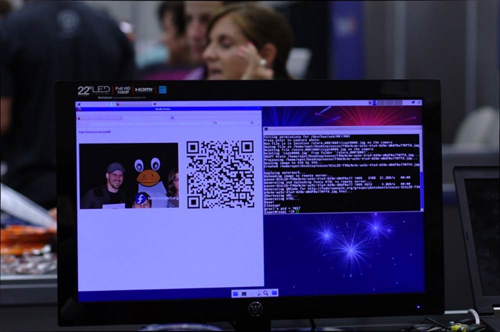
Figure 5-10. Output of photobooth.py
Choose a location to store the assorted data that goes along with your photo:
# Where to spit out our qrcode, watermarked image, and local html
out = expanduser('~/Desktop/photodata')
You can add a watermark to your images, such as a project name (you can also exclude this line if you don’t want the photos watermarked):
# The watermark to apply to all images
watermark_img = expanduser('~/Desktop/fedora.png')
You’ll need to have a place you can upload the pictures to. You’ll also need a stable Internet connection, which can be problematic if you’re setting up a photobooth at an event like a conference. If that’s the case, be sure to get a wired connection and not try to do this over WiFi:
# This assumes ssh-agent is running so we can do password-less scp
ssh_image_repo = 'fedorapeople.org:~/public_html/photobooth/'
# The public HTTP repository for uploaded images
http_image_repo = 'http://lmacken.fedorapeople.org/photobooth/'
[source, python]
Define the size of the QR code you want to display:
# Size of the qrcode pixels
qrcode_size = 10
# Whether or not to delete the photo after uploading it to the remote server
delete_after_upload = True
[source, python]
People will scan the QR code to visit your web page and download their photos. Then choose whether to save photos after they’ve been uploaded. If you’re doing this at a conference, that directory can fill up quickly if you save them!
When you want to change picture quality and size or are having trouble with the photo, you’ll want to consult the gphoto2 configuration options, which you can set here:
# The camera configuration
# Use gphoto2 --list-config and --get-config for more information
gphoto_config = {
'/main/imgsettings/imagesize': 3, # small
'/main/imgsettings/imagequality': 0, # normal
'/main/capturesettings/zoom': 70, # zoom factor
}
Choose which service to use to create your short URLs (options include a.gd, bit.ly, burnurl.com, cli.gs, decenturl.com, digg.com, is.gd, kl.am, liip.to, metamark.net, sn.im, snipr.com, snipurl.com, snurl.com, tinyurl.com, tr.im, turl.ca, ur.ly, and zz.gd):
# The URL shortener to use
shortener = 'tinyurl.com'
The Photobooth class includes most of the hard work for this setup:
class PhotoBooth(object):
def initialize(self):
""" Detect the camera and set the various settings """
cfg = ['--set-config=%s=%s' % (k, v) for k, v ingphoto_config.items()]
subprocess.call('gphoto2 --auto-detect ' +
' '.join(cfg), shell=True)
def capture_photo(self):
""" Capture a photo and download it from the camera """
filename = join(out, '%s.jpg' % str(uuid4()))
cfg = ['--set-config=%s=%s' % (k, v) for k, v ingphoto_config.items()]
subprocess.call('gphoto2 ' +
'--capture-image-and-download ' +
'--filename="%s" ' % filename,
shell=True)
return filename
def process_image(self, filename):
print "Processing %s..." % filename
print "Applying watermark..."
image = self.watermark(filename)
print "Uploading to remote server..."
url = self.upload(image)
print "Generating QRCode..."
qrcode = self.qrencode(url)
print "Shortening URL..."
tiny = self.shorten(url)
print "Generating HTML..."
html = self.html_output(url, qrcode, tiny)
subprocess.call('xdg-open "%s"' % html, shell=True)
print "Done!"
If you choose not to watermark, you’ll want to delete this section:
def watermark(self, image):
""" Apply a watermark to an image """
mark = Image.open(watermark_img)
im = Image.open(image)
if im.mode != 'RGBA':
im = im.convert('RGBA')
layer = Image.new('RGBA', im.size, (0,0,0,0))
position = (im.size[0] - mark.size[0], im.size[1] - mark.size[1])
layer.paste(mark, position)
outfile = join(out, basename(image))
Image.composite(layer, im, layer).save(outfile)
return outfile
The script continues by uploading the image, creating the QR code and the web page, and offering a shortened URL:
def upload(self, image):
""" Upload this image to a remote server """
subprocess.call('scp "%s" %s' % (image, ssh_image_repo), shell=True)
if delete_after_upload:
os.unlink(image)
return http_image_repo + basename(image)
def qrencode(self, url):
""" Generate a QRCode for a given URL """
qrcode = join(out, 'qrcode.png')
subprocess.call('qrencode -s %d -o "%s" %s' % (
qrcode_size, qrcode, url), shell=True)
return qrcode
def shorten(self, url):
""" Generate a shortened URL """
return surl.services.supportedServices()[shortener].get({}, url)
def html_output(self, image, qrcode, tinyurl):
""" Output HTML with the image, qrcode, and tinyurl """
html = """
<html>
<center>
<table>
<tr>
<td colspan="2">
<b><a href="%(tinyurl)s">%(tinyurl)s</a></b>
</td>
</tr>
<tr>
<td><img src="%(image)s" border="0"/></td>
<td><img src="%(qrcode)s" border="0"/></td>
</tr>
</table>
</center>
</html>
""" % {'image': image, 'qrcode': qrcode, 'tinyurl': tinyurl}
outfile = join(out, basename(image) + '.html')
output = file(outfile, 'w')
output.write(html)
output.close()
return outfile
if __name__ == "__main__":
photobooth = PhotoBooth()
try:
photobooth.initialize()
while True:
raw_input("Press enter to capture photo.")
filename = photobooth.capture_photo()
photobooth.process_image(filename)
except KeyboardInterrupt:
print "\nExiting..."
Change the various settings to meet your needs, and your photobooth party is all set up. (Tux costume optional and not included with this book.)
Hack 54. Turn Your Pi into a Tiny Media Center
The first thing that many people want to do with their new $35 computer is turn it into a tiny media center, so we’d be remiss in not helping you out.
This hack is going to veer off a bit from what you’ve read so far, as far as distro. We’ve been telling you how to do things in Pidora and Raspbian, two of the most common Raspberry Pi Linux distributions. Since we both work on Fedora, you can imagine we have an inclination toward Pidora. But you can also see that we’ve been giving you instructions throughout this book for Raspbian as well, and occasionally only one or the other. That’s because sometimes one distro simply is the right one for the job, and in this case, it’sRaspbmc.
If you’re going to set up a media server, you want it to work as well as possible, becase it’s standing between you and [insert your favorite show here]. That means you might as well use XBMC (regardless of how you feel about the Xbox—see “XBMC” sidebar), as it’s commonly used, which means it has a significant community waiting with answers to any problems you encounter. And because it’s so popular, a distro has sprung up specifically intended for it. That’s Raspbmc.
XBMC
XBMC was originally created for the Xbox and stood for Xbox Media Center. It’s now available for Linux as well as Windows, OS X, and even Android and iOS. Their release names are all allusions to popular media. Releases so far have been Atlantis, Babylon, Camelot, Dharma, Eden, Frodo, and Gotham.
You can download the Raspbmc image and set up your SD card like you would with any other distribution, but the Raspbmc folks have also made an interactive installer to make it easier for you. Note that if you use the installer, you will need a network connection to the Pi at first boot for setup.
First, get the installer:
$ wget http://svn.stmlabs.com/svn/raspbmc/release/installers/python/install.py
$ chmod +x install.py
$ sudo python install.py
[source, bash]
These three commands will then start the installer, as shown in Figure 5-11.
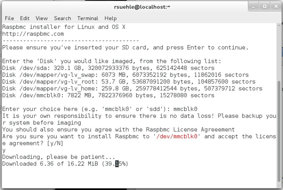
Figure 5-11. Raspbmc installer
Once installation is complete, you will be asked:
Would you like to setup your post-installation settings [ADVANCED]? [y/N]
If you say yes, you will be asked two questions:
Would you like to install Raspbmc to a USB stick or an NFS share?
Note that this still requires an SD card for booting. [y/N]
Would you like to configure networking manually? This is useful if you are configuring WiFi or a non-DHCP network [y/N]
Once you have answered them, you will be told:
Raspbmc is now ready to finish setup on your Pi, please insert the SD card with an active internet connection
Connect your Ethernet, keyboard, and mouse to the Pi. Insert the SD card and plug it in for first boot. If you don’t have a network connection, you’ll get an error on a blue screen:
Sorry, I couldn't connect to the update server. Please verify you have a wired network ocnnection or properly configured wireeless connection and disable any proxy servers on your network.
After you have done this, unplug your Raspberry Pi for 60 seconds before trying again.
Assuming it does find the network connection, you’ll get a message telling you that this is going to take 15–20 minutes.
Once it’s finished, XBMC is ready to go. Restart the system, and you can start using your new media center. Periodically, XBMC will offer helpful tips when you do something for the first time (it’s quite user-friendly). All that’s left is to decide what to entertain yourself with!
XBMC supports just about any format you want to throw at it. You can watch DVDs and unencrypted Blu-ray discs. You can play CDs. For files you have on a drive, you can play, watch, or listen to more file types than you can name off the top of your head, including all the standard video formats—even the open Ogg format.
If you doubt the thoroughness of the options, acceptable audio files include NSF (NES Sound Format), SID (Commodore 64), and YM (Atari ST). The XBMC wiki has a complete list of supported types for reference.
XBMC will communicate over all sorts of networking protocols, including AirPlay, UPnP, SMB/SAMBA/CIFS, NFS, NTP, and WebDAV. (And that’s just a start.)
Decode MPEG-2 and VC-1
The Raspberry Pi doesn’t include a license to decode MPEG-2 or VC-1. That decision was made to keep the price of the device as low as possible. Then everyone wanted to use the Pi for a media center with their existing libraries that included MPEG-2 encoded files.
If that includes you, you can purchase an inexpensive MPEG-2 license from the Raspberry Pi store. Microsoft’s VC-1 license is also available. Unfortunately, this isn’t instant gratification, so plan ahead. The licenses are generated offline and sent to you within 72 hours of purchase.
To purchase one, you’ll need your serial number, which you can find easily:
$ cat /proc/cpuinfo
Processor : ARMv6-compatible processor rev 7 (v6l)
BogoMIPS : 795.44
Features : swp half thumb fastmult vfp edsp java tls
CPU implementer : 0x41
CPU architecture: 7
CPU variant : 0x0
CPU part : 0xb76
CPU revision : 7
Hardware : BCM2708
Revision : 000e
Serial : 0000000011185abc
The last line, Serial, is the part you’ll need in order to purchase a license. When you receive your license, it will be a text file with one line that says something like decode_MPEG2=0x8675309. Edit the config file on your Raspberry Pi:
$ sudo vi /boot/config.txt
Add the license information as a new line at the bottom, save, and exit. Reboot your Pi, and you’re ready to go. Because this is in the configuration file on the distribution, if you change distributions or reinstall your card, you will need to add the license again. Because the code is linked to the serial number of the Pi, however, you will need to purchase a separate license for each physical Raspberry Pi you want to use it on.
Add a Remote Control
Once you’ve been using your new Pi media center and decided you like it, you might feel it’s missing one familiar piece: a remote control. Flirc is a small USB dongle that turns whatever remote control you have lying around the house into your new XBMC remote control. You can buy it from Flirc directly or one of their distributors, including The Pi Hut and ModMyPi.
Bonus: a portion of the profits go to the USC Cancer Research Facility.
You can set up Flirc on your PC (Windows, Mac, or Debian/Ubuntu) with a simple .exe, .dmg, or by adding Flirc to your apt-get sources list. Instructions and downloads for each are available at http://www.flirc.tv/downloads.
Once you install the software and start it, you’ll see the screen shown in Figure 5-12.
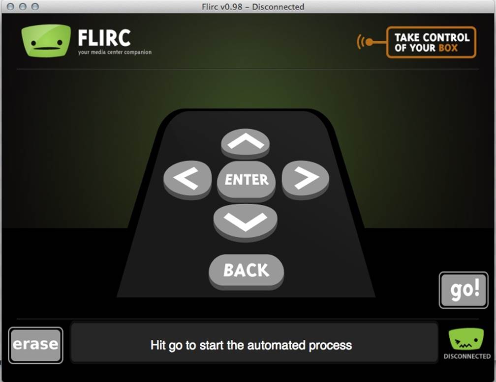
Figure 5-12. Flirc setup screen
Plug in the Flirc dongle and let it run its automatic setup. Then you’re ready to connect it to your remote control.
As each button on the on-screen Flirc remote flashes, press a button on your remote control to associate with that button. A few presses later, your remote control is now your XBMC remote control. You can unplug the Flirc dongle and plug it into your Raspberry Pi.
At this point, it is safe to unplug the mouse and keyboard, since you’ll be using the remote control you just set up. (And unless you have a hub handy, you’ll need one of those USB ports for it!) Flirc does offer some options specifically for XBMC—click Controllers, and choose XBMC from the drop-down.
If you’d like to explore other options for remote controls with XBMC, the XBMC wiki offers several other options. This is particularly useful if you’d like to use a Media Center Edition (MCE) remote, which is meant to work with Microsoft Windows and Windows Media Center. These may not function well with Flirc.
Shortcut for Cord Cutters
One of the downsides to cutting the cord and ridding yourself of a cable or satellite service is that things don’t just come on. You have to turn on your TV and wait for your Playstation 3 or Roku or whatever device you’re using (now a Raspberry Pi!) to start as well. You can plug the Pi into a separate power outlet and leave it running all the time so that when you turn on your TV, you don’t have to wait for it to boot. Or, if you’d rather not consume power and keep the Pi running when you’re not watching TV, there’s another option.
If your TV has a USB port, try connecting it to your Raspberry Pi for power. It might not work, but sometimes it does. And if it does, your Pi will boot when you turn on the TV, and you’re one step closer to your favorite shows. We still can’t make whatever you were hoping to watch magically appear when you turn on your TV, but maybe this will cut out one extra step. The downside to this approach is that most TVs cut the power to the USB port when the TV is turned off. This leads to a regular pattern of abrupt OS shutdown, which may shorten the life of your SD card in your Raspberry Pi, or at the very least, require the filesystems on it to be repaired with fsck more often.
Add Some Content
Now that you have a media center, what are you going to watch? If you’re like us, you’d like to be able to get your Hulu and Netflix subscriptions in there. The easiest way to do so is with one more paid service: PlayOn.
PlayOn combines content from a wide source of online providers and makes it easy for you to find and consume. We’ve been using it for some time now and can genuinely recommend that it’s worth the cost. The price varies with changing sales, but even a lifetime subscription is probably half or less of one of your monthly cable bills.
PlayOn is a really handy server for a Windows machine (that’s the one downside: you need an extra machine, and only Windows will do) that streams your video content to just about any device. To get content to your TV, however, it needs a helper friend, like your new Raspberry Pi with XBMC. You can use it to play your subscription services, including Netflix, Hulu, and Amazon Instant Video. There are also plenty of free channels. If you want to be sure that the stuff you watch is available before you sign on, you can use thePlayOn Show Finder.
Once you purchase your PlayOn subscription and install it on your Windows computer, you’ll need to enter your registration license in the PlayOn Settings (Start → All Programs → PlayOn → PlayOn Settings) on the Registration tab, as shown in Figure 5-13.
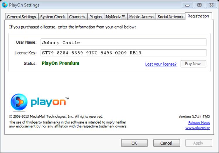
Figure 5-13. PlayOn registration dialog
Once you’ve done that, go to the Videos menu on your XBMC setup to tell it about the PlayOn share.
Click the Files tab under Videos. From that screen, select Files → Add Videos. Click Browse → UPnP Devices. In that list, you should see PlayOn. Click it, and click OK, and XBMC will list it by it UPnP address (Figure 5-14).
Click OK to confirm, and you’ll see the list of available services and channels (Figure 5-15).
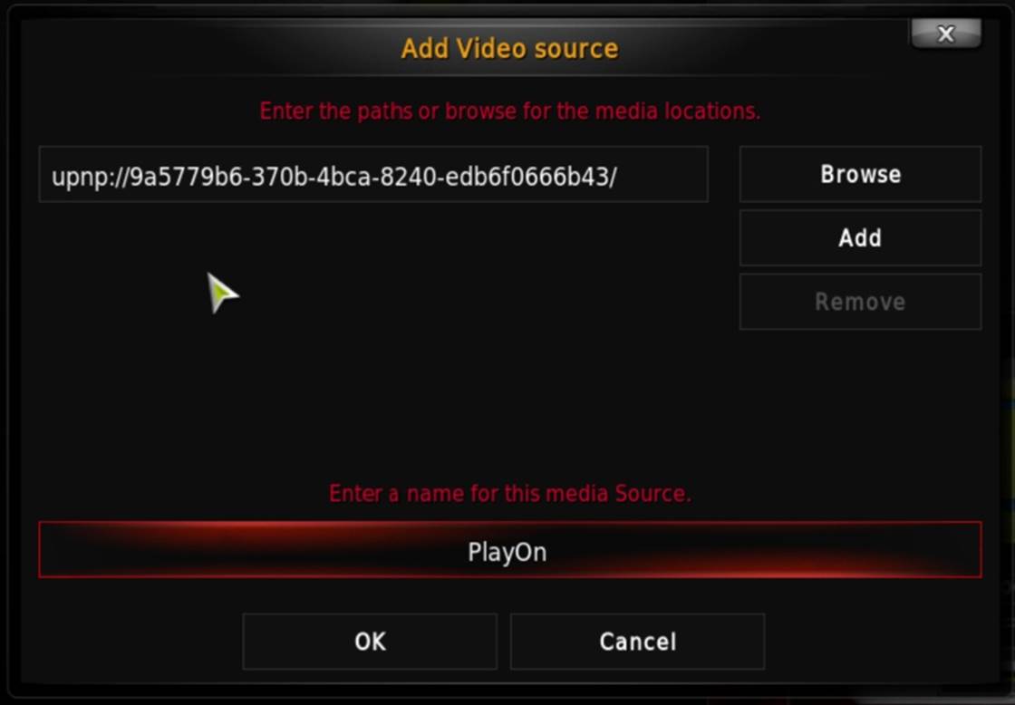
Figure 5-14. PlayOn setup screen in XBMC
Figure 5-15. PlayOn channel list in XBMC
Enjoy all of your favorite shows… right after you finish reading this book.
Hack 55. Watch Movies in the Backseat of Your Car
If you’re a parent, you know that long trips in a car with children can be…trying. Why not build a relatively inexpensive, in-car media player?
The idea of a TV screen in the car is not at all new. In fact, you can right now drop a few thousand dollars and have one installed that plays DVDs from your dashboard. Or, you can spend significantly less and build something yourself that plays practically anything you can think of.
Our good friend, the Raspberry Pi, is small, efficient, and it plays movies very, very well, thanks to its dedicated hardware support for video codecs. Here’s what you need to hack it together for those long car trips that need a little entertainment.
Your Reliant (in Terms of Power) Automobile
Really, any make or model of car should work for this, with one caveat: power. A bit of a history lesson is probably appropriate here.
Once upon a time, it was cool to smoke cigarettes, and car manufacturers felt like they were doing their customers a major service by providing an on-demand heat source that they could use to light their smokes. This device works by connecting a thin coil of nichrome wire to a high current from the car’s electrical system. You’d push the handle in, the current would heat up the coil, and in a few seconds, the lighter would heat up (it would actually glow orange/red hot) and then the handle would pop out. You could then press the tip to your cigarette and enjoy the act of giving yourself lung cancer on the go.
Today, most people choose not to use those cancer sticks, but these “cigarette lighter” receptacles remain. Why? Because these ports provide 12 volts of electricity, and we have a lot of power-hungry gadgets that need juice. While some new vehicles provide dedicated USB (or even pronged power outlets), most of them still provide these standard, 12 V “cigarette lighter” plugs. In fact, a lot of cars that have them available intend for them to power only compatible accessories and don’t actually include the actual lighter (many even include an explicit message that states “this is not a cigarette lighter”).
These 12 V receptacles will power the parts for this hack. You’ll need three of them to do it the way described here. You might be able to get away with using only two, but you’d have to power your Raspberry Pi from a powered USB hub that also powers devices connected to the same Raspberry Pi, and that isn’t usually very reliable.
If you need more receptacles than your car has available, there are a few ways to hack around that. You can get a socket splitter, which will expand a single socket out to two. Some socket splitters even add a USB port in addition to the two sockets. With that setup, you could run everything that this hack needs off one 12 V receptacle. Other ways to get the power to your devices involve more complicated hardware setups or custom electrical wiring, so we’re not going to cover them here.
YOUR CAR IS A SPECIAL SNOWFLAKE
Keep in mind that some cars might have these receptacles wired up differently. For example, on the Dodge Caravan, some of the 12 V ports are wired to the ignition and provide power only when the car is turned on. Other ports provide power directly from the battery and will have juice even when the engine isn’t running. Every make, model, year, and variant of vehicle will have its own eccentricities in this regard, so you should consult your owner’s manual to understand the ground rules.
Assuming you don’t have a USB power port available (either via a splitter or included in your car), you’ll need to get a 12 V-to-USB converter. These are a lot more commonly available (and a lot less expensive) than they used to be, but the fact is that you get what you pay for with these converters. A good rule of thumb is that if they’re free, they’re junk.
Let us elaborate on that a little bit before you go off to rage-trash your free converters that you picked up as swag at your last tech conference. Most of these converters assume that you are plugging in a phone or a tablet into them. In fact, they even assume you’re plugging in an Apple phone or tablet. Apple devices charge over USB at 1 amp of current, so these cheap/free converters often don’t offer up more than 1 amp of current, nor do they try very hard to make that current very clean or regular.
This results in a slow charge for most other devices. Although other devices (such as your Android phone or tablet) will take 1 amp, they generally prefer 2.1 amps of current or even more, depending on the device, and as a result, can charge faster. These cheap converters also have a nasty tendency to be assembled poorly, resulting in a quick converter death if it overheats (or just has pieces fall off).
As a result, we recommend that you connect your Raspberry Pi to a high-quality converter that provides 2.1 amps of current. We’ve seen good results from the Mediabridge High Output Dual USB Car Charger on the 2.1AMP port, but anything with a dedicated 2.1AMP port (and a total rating of at least 3.1 amps) should do the trick.
We do not recommend that you use a 12 V converter cable designed for charging a phone (especially not a third-party provided cable), because they often have the same problems as the cheap converters do. Acceptably poor for a phone, but no good for an “always-on” Raspberry Pi. As always, your mileage may vary (YMMV), so don’t rush to post an angry but it works for me rebuttal online. Things that shouldn’t work sometimes do.
The touchscreen used in this hack (more about that in Touchscreen) comes with a power cable to connect directly to a 12 V receptacle, so you won’t need to worry about it. However, because you need a powered USB hub to prevent the Raspberry Pi from using too much power (and simply turning off or behaving erratically), you will need to get an inverter.
In this context, an inverter is a device that takes the 12 V DC power coming from the “cigarette lighter” and changes it to an AC power outlet (the amount of wattage provided varies by the unit). These inverters vary in quality (and functionality), but because you need to plug only one thing into it, 200 watts should be enough.
We have successfully used a number of 300-watt inverters on the market. If you want to spend the money, you can get a pure sine-wave inverter that provides an exact replica of AC household power with two ground fault protected outlets and will likely work foryears reliably and silently. This comes with a cost, though, as they run about $175.
Instead, you can get a modified sine-wave inverter for $20–30. These do not work as reliably, but they should work to power a USB hub. They’re also a lot louder and hotter, usually with fans running all the time.
Storage for Your Movies
The next thing you’re going to need is a place to put your digital video files. While you could put a few of these onto the SD card running the Raspberry Pi, that space will fill up quickly (and these files are usually quite large).
You’ll also need to factor in the fact that you’re installing this in a moving car. That rules out a traditional portable hard drive, because it has moving parts and is not usually very tolerant of a lot of bumps.
Instead, you’re going to use a solid state drive (SSD). The technologies behind SSDs have been around since the 1950s, but since then, they’ve gotten much bigger (in capacity), much smaller (in size), and much cheaper (in cost). SSDs are basically big blocks of memory without any mechanical moving parts. This makes them very fast, but more importantly for this hack, they work perfectly through every bump and bounce of your car.
You can connect an SSD to the Raspberry Pi over USB. Purchase a drive that is designed to be external, or buy an internal SSD and put it in an external USB chassis. At this point, the majority of these USB chassis units are USB 3.0, due to the high speed (up to 5 Gbit/s at half duplex, twice that at full duplex). This is fine, but the Raspberry Pi can only communicate across its USB bus at USB 2.0 speeds (up to 480 Mbit/s), and USB 2.0 is limited to half-duplex rates. Because USB 3.0 is backward-compatible to USB 2.0, this is not a problem, but you won’t get USB 3.0 speeds out of the drive.
Whether you buy a premade external drive or use a separate chassis, you want to make sure it draws its power from the USB port, not from an external adapter. If it did that, you’d have something else you needed to plug into the inverter, and that really isn’t necessary.
You should also remember that you cannot boot your Raspberry Pi from this SSD. You’ll just be mounting it as a storage partition where you will put your movies.
Touchscreen
You could use a TV or a monitor that connects to the Pi’s video outputs (either HDMI or composite), but then you’d have to interface with the Raspberry Pi through a keyboard or a mouse, and that’s not ideal in a moving car (definitely not if you want your kids to use this setup from the backseat).
Instead, this hack uses a touchscreen. If you’ve been looking through this book, you may have noticed we have a separate hack ([Hack #50]) that covers how to add a touchscreen to a Raspberry Pi, but that particular type of touchscreen is not a good choice here. It is a DisplayLink device, which means it doesn’t use the HDMI or composite outputs on the Raspberry Pi. Since the Raspberry Pi can decode hardware video using only those output devices, you’ll need a touchscreen that is connected to them (instead of just over USB).
The part we found for this came from a company called Chinavasion, with the highly descriptive name of 7 Inch HD Touchscreen Car Monitor. This nifty little unit supports HDMI input at 1720x1440 (not quite 1080p, but still, not shabby), but it also has an integrated touchscreen with Linux support. It is not super cheap (about $150 at the time of this writing), but it is designed for use in a car, so it comes with a native 12 V power cable.
Powered USB Hub
You’ll need a powered USB hub. Hypothetically, you could try to get away with just plugging your touchscreen and SSD into the Raspberry Pi directly, but practically, we’re telling you not to try that. Your Pi is far more likely to simply turn off when you try that, and you won’t be able to attach any other components, like a keyboard or mouse (for debugging the setup) or a wireless network controller (for downloading files or connecting to the Internet from a coffee shop on the road).
The brand or model doesn’t matter so much here. The most important detail is this: it needs to be externally powered. You need to be able to plug it into the wall, or in this case, into the inverter plugged into the 12 V receptacle. Many inexpensive USB hubs are not externally powered and draw their power from the USB cable that it uses to connect to your computer (in this case, the Raspberry Pi). Since you’re trying to work around the power limitations of the Raspberry Pi, this really will not work. If you want more of the gory details about why, see [Hack #8].
You will be connecting two devices to the USB hub: your touchscreen and your portable SSD, so make sure your hub has enough juice coming from its power adapter to provide .5 A to two ports.
Software
Technically, you could use almost any Linux distribution here, but we strongly recommend using RaspBMC for this purpose. This customized version of Debian with XBMC preinstalled is ideal for the needs of this hack. XBMC is a robust and featureful suite of software that provides a GUI interface for a media center. RaspBMC has been customized specifically to support the hardware decoding and output features of the Raspberry Pi.
Connect your Raspberry Pi to your touchscreen (video to the HDMI port) and your external USB hub. Plug the touchscreen’s USB cable into the USB hub, along with a normal keyboard and mouse. You’ll need these input devices at first, because the touchscreen won’t work yet. Then insert a new SD card into your Linux laptop and install RaspBMC onto it. We have a whole hack on how to install RaspBMC to the Pi, so flip over to [Hack #54] and follow those instructions. Come back when you’re done; we’ll wait.
WHAT ABOUT OPENELEC?
If you want to use something other than RaspBMC, OpenELEC will probably work, but you’ll need to build a custom kernel for it that has support for touchscreens. If you follow the instructions in [Hack #22], it should work.
Welcome back! You should now have a shiny (and Raspberry-tinted) RaspBMC session displaying on your touchscreen.
Enabling Touchscreen Support
If you touch the touchscreen now, you will probably notice that it does respond, but not properly. The mouse cursor will jump around, seemingly at random. It isn’t really random, though; it just isn’t properly calibrated yet. The good news is that it is already detected, and the proper Linux kernel drivers are loaded (RaspBMC is very clever).
To calibrate the touchscreen, you will need to SSH into the RaspBMC session to enable the touchscreen. To determine the IP address of your Raspberry Pi, navigate (with the mouse) over to to the System menu (it is the farthest item to the right), then to the System info tab. It will print out a page of system information details, including a field labeled “IP address.”
From your Linux laptop, SSH into that IP address as the pi user. We’ll assume the IP address is 192.168.5.128 in these examples, but you should of course replace it with your actual IP address:
$ ssh pi@192.168.5.128
The default password is raspberry. Once you successfully SSH in, RaspBMC will prompt you to set your locale and keyboard settings. For Americans, it’s en_US.UTF-8 UTF-8. If you don’t know your locale setting, you can enable “All locales” at the top, but it will eat up space on the SD card.
After this finishes, you can set the timezone, and finally, it will drop you to a shell prompt, where you can get down to the business of calibrating the touchscreen. First, go ahead and stop XBMC:
$ sudo stop xbmc
Download and install the touchscreen library and calibration script:
$ wget --no-check -O tslib_1-1_armhf.deb "https://docs.google.com/uc?export=download&id=0B4lrG9aRe-8MUlRaRW5LcXNDaDA"
$ sudo dpkg -i tslib_1-1_armhf.deb
$ wget --no-check -O ts_calib.sh "https://docs.google.com/uc?export=download&id=0B4lrG9aRe-8MOV94Nl90SExsVE0"
$ chmod +x ts_calib.sh
You’ll need to configure the ts_calib.sh calibration script before it will work properly. Specifically, you need to know the device name for the touchscreen’s event device. The easiest way to determine this is to run ls -l /dev/input/by-id:
$ ls -l /dev/input/by-id
total 0
lrwxrwxrwx 1 root root 9 Sep 12 21:19 usb-Logitech_USB_Keyboard-event-if01 -> ../event3
lrwxrwxrwx 1 root root 9 Sep 12 21:19 usb-Logitech_USB_Keyboard-event-kbd -> ../event2
lrwxrwxrwx 1 root root 9 Sep 12 22:23 usb-Logitech_USB_Optical_Mouse-event-mouse -> ../event4
lrwxrwxrwx 1 root root 9 Sep 12 22:23 usb-Logitech_USB_Optical_Mouse-mouse -> ../mouse2
lrwxrwxrwx 1 root root 9 Sep 12 21:19 usb-eGalax_Inc._Touch-event-mouse -> ../event1
lrwxrwxrwx 1 root root 6 Sep 12 21:19 usb-eGalax_Inc._Touch-mouse -> ../js0
The touchscreen in this example is an “eGalax Inc.” touchscreen, so the event device is event1. Edit ts_calib.sh with your favorite text editor, and change the TSLIB_TSDEVICE line to reflect the proper event device. For the setup in this example, it should look like this:
export TSLIB_TSDEVICE=/dev/input/event1
Save it to disk, and then run it (as root):
$ sudo sh ./ts_calib.sh
xres = 1280, yres = 720
The touchscreen display should flash, then display a calibration screen with a crosshair. Carefully tap the crosshair with the included stylus (or, if you’ve already lost the stylus, the tip of a click pen with the ink tip not pushed out). It will move around the screen to all four corners, then to the center. When you finish, it will print the calibration values out to the terminal, and the calibration is done.
Now you need to use uinput-mapper to map the touchscreen input to an input device that xbmc finds friendlier. To be specific, it lets you map specific touch behaviors to various mouse click types. Download the software and the configuration, and install it into the/scripts directory:
$ wget --no-check -O uimapper.tar.gz "https://docs.google.com/uc?export=download&id=0B4lrG9aRe-8Malg2VkM0YW1CT28"
$ wget --no-check -O uimapper.conf "https://docs.google.com/uc?export=download&id=0B4lrG9aRe-8MM2RIWFh1WjJWUW8"
$ sudo mkdir -p /scripts
$ sudo tar -xf uimapper.tar.gz -C /scripts
Edit uimapper.conf with your favorite text editor, and correct the UIMAPPER_DEV line to reflect the event device you found earlier:
env UIMAPPER_DEV="/dev/input/event1"
Save out the file, and move it (as root) into position inside /etc/init. This will allow uinput-mapper to start when the RaspBMC instance boots:
$ sudo mv uimapper.conf /etc/init
You need to tweak the internal uinput_mapper configuration a bit before it will work properly. Open /scripts/uinput_mapper/configs/touchscreen.py in a text editor (as root) and change this line:
sres = subprocess.check_output("tvservice -s", shell=True)
to look like this:
sres = subprocess.check_output("/opt/vc/bin/tvservice -s", shell=True)
Without that change, the uinput_mapper upstart service will fail to find the tvservice binary and silently fail.
Your touchscreen should be ready. Reboot your Raspberry Pi to test it:
$ sudo shutdown -r now
When it comes back up, try touching the screen. The cursor should move to where you touched. If you want to “touch” a click, touch and hold for a half-second and then release. It will take some getting used to. This setup should work simultaneously with any other attached input devices (such as a keyboard and mouse), so if you want to have an “override” console, you can add that easily.
If you need to debug the uinput_mapper service, first stop the xbmc service:
$ sudo stop xbmc
If you do not do this, XBMC will hold the uinput_mapper device, and you won’t be able to access it with anything else for debugging. You can install the evtest utility from the Raspbian repository and use it to debug the events that the touchscreen is registering:
$ sudo apt-get install evtest
$ evtest
No device specified, trying to scan all of /dev/input/event*
Not running as root, no devices may be available.
Available devices:
/dev/input/event0: eGalax Inc. Touch
/dev/input/event1: eGalax Inc. Touch
/dev/input/event2: Logitech USB Keyboard
/dev/input/event3: Logitech USB Keyboard
/dev/input/event4: Logitech USB Optical Mouse
/dev/input/event5: uimapper - touchscreen
Select the device event number [0-5]: 5
Input driver version is 1.0.1
Input device ID: bus 0x3 vendor 0x42 product 0xbebe version 0x1
Input device name: "uimapper - touchscreen"
Supported events:
Event type 0 (EV_SYN)
Event type 1 (EV_KEY)
Event code 106 (KEY_RIGHT)
Event code 273 (BTN_RIGHT)
Event code 320 (BTN_TOOL_PEN)
Event code 330 (BTN_TOUCH)
Event type 3 (EV_ABS)
Event code 0 (ABS_X)
Value 0
Min 0
Max 2047
Event code 1 (ABS_Y)
Value 0
Min 0
Max 2047
Event type 4 (EV_MSC)
Event code 4 (MSC_SCAN)
Properties:
Testing ... (interrupt to exit)
When evtest prompts you to select the device, choose the uimapper device and then touch away (and hold touch and double-touch). You will see the different signals that uinput_mapper is generating as a result of your touches. If you do not see a uimapperdevice at this screen, it means that the uinput_mapper service is either stopped or not running properly.
Adding Videos
If you have not already done so, put your videos on your SSD. The SSD can be formatted for any filesystem that RaspBMC understands (NTFS, FAT, ext2/3/4, etc.), and your video files can be in any directory or folder hierarchy that you want. Just be aware that XBMC will force you to navigate through those folders to play your videos, so we recommend keeping it as shallow as possible. You can also add music or pictures in this same way.
SUPPORTED ENCODINGS
By default, the Raspberry Pi hardware supports hardware decoding of only H264/MPEG-4 video encoding. RaspBMC will try to play files that are encoded with other video codecs, but it might have to fall back to software decoding to do so, and the performance of that will be poor. For more details on how to add additional hardware video codecs, see [Hack #47].
When you plug the SSD into the USB hub, if RaspBMC is running, it will automatically detect the additional drive, and you will be able to select that source for your videos (or music/pictures). You should test it out now to make sure you can successfully playback videos. The touchscreen has small speakers that will play the HDMI audio being output by the Raspberry Pi.
Putting It All Together
Now that everything works properly, you just need to put it in your car. Plugging in the power should be straightforward: you plug the touchscreen into one 12 V receptacle, your power inverter (to household AC power plug) into another, and then plug the Raspberry Pi into a third one (or a USB port if it is available). The SSD and the touchscreen USB connectors should be plugged into the USB hub, and the USB hub should have its interconnect hooked to the Raspberry Pi. The touchscreen HDMI connector should be connected directly to the Raspberry Pi.
The touchscreen includes mounting plates, so you can mount it directly to the car seat, but if you are crafty, you can make a container that will hang over the back of the headrest of a front seat that encapsulates all of this loose hardware.
It is also possible for you to hide it all away in your car by hacking it into the empty spaces (or carving out empty spaces). There is no one right way to do this, and it’s dependent on your vehicle’s design, so we leave it up to you to figure out what works best for your car.
All materials on the site are licensed Creative Commons Attribution-Sharealike 3.0 Unported CC BY-SA 3.0 & GNU Free Documentation License (GFDL)
If you are the copyright holder of any material contained on our site and intend to remove it, please contact our site administrator for approval.
© 2016-2026 All site design rights belong to S.Y.A.