Raspberry Pi Hacks (2014)
Chapter 6. Extend Your Pi
The real magic of the Raspberry Pi happens when you make it a part of something else. Use the GPIO to connect it to new devices ([Hack #56]). Connect Arduino shields ([Hack #58]). Add a tiny screen ([Hack #57]), numeric keypad ([Hack #60]), or heat sink ([Hack #61]). Do all of them, and make something amazing. This chapter is to help get you started taking the Pi beyond mere Linux computer into something more.
Hack 56. Control GPIO from a Web Browser
Your Raspberry Pi GPIO interface is a gateway to an entire Internet of Things. Here is a simple way to access it from a web browser.
Every day, more and more devices become network-aware, either intentionally or as a result of clever hacks. This phenomenon has many names, but the most common seems to be “Internet of Things.” You can use your Raspberry Pi to help your dumb devices get smart and join the Internet of Things.
The best way to connect your Pi to other devices is via the GPIO expansion ports. If you’re not sure what that means, go take a quick read through [Hack #14]. These digital pins will let you wire almost anything into your Raspberry Pi, but once the physical connection is made, you’ll want a framework in place to actually do something.
Eric PTAK created a REST framework and web app to control the Raspberry Pi and its GPIO through the Web. Called WebIOPi, this framework allows you to use and control your Pi’s GPIO over the Internet (or through a number of language bindings and APIs).
To install it, start with a current image of Raspbian. Then, from the running instance of Raspbian, download and install the WebIOPi code:
$ wget http://webiopi.googlecode.com/files/WebIOPi-0.6.0.tar.gz
$ tar xvzf WebIOPi-0.6.0.tar.gz
$ cd WebIOPi-0.6.0
$ sudo ./setup.sh
You might want to check the WebIOPi website to make sure that 0.6.0 is still the latest version before proceeding. If it has been updated, adjust appropriately.
The setup script (setup.sh) will download and install the necessary WebIOPi dependencies from the apt-get repositories in Raspbian, then build the code and install it into the proper locations.
When this finishes, you’ll have a WebIOPi service that you can run and access via a web browser. To turn it on, run:
$ sudo /etc/init.d/webiopi start
You can then connect to it from within the Raspbian session by opening a web browser and navigating to http://localhost:8000/. If you want to connect to it from a remote system, you can replace localhost with either the IP address or fully qualified hostname of the Raspberry Pi. For login credentials, the user is webiopi and the password is raspberry.
Once connected, you will be able to view a graphical representation of the Raspberry Pi GPIO header (click on the “GPIO header” link), as shown in Figure 6-1. From this page, you can swap the direction on the Input/Output pins (not on the power or Ground pins, for what are hopefully obvious reasons).
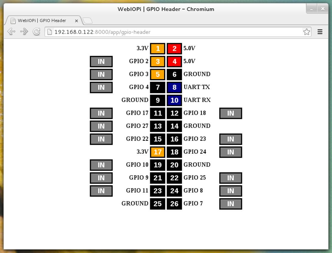
Figure 6-1. WebIOPi browser showing GPIO view
WebIOPi is capable of doing a lot more than this though. It provides a Python library that contains support for all kinds of GPIO interactions, including explicit support for digital-to-analog converters (DAC), analog-to-digital converters (ADC), common sensors, I2C, serial, and SPI devices.
Additionally, the web application itself allows you to monitor and debug these same devices and connections. It also includes Java and Javascript libraries that will enable you to make custom web (and Android) clients to interface with and remotely control devices that are connected through the Raspberry Pi GPIO.
Finally, because WebIOPi talks REST, you can interface to it through any other language that you choose, but the native libraries are a bit more friendly.
Hack 57. Add a Tiny Screen
Sometimes it’s just not convenient to carry around a full-sized monitor. Maybe you want to build a tiny, portable computer. There are screens for you!
When we decided to start working on portable Raspberry Pi projects, we chose Adafruit’s 2.5” NTSC/PAL display, partly for the quality and partly because it was one of the few options at the time. It has RCA connections, 32 levels of backlight brightness you can adjust with buttons, and a switch that changes it from portrait to landscape display.
The one downside for connecting this piece to your Raspberry Pi is that it has a female RCA jack, just like your Pi. There are male-male RCA connector pieces, which is what we’ve used here to connect them, but that adds about an inch and a half of inflexible metal bulk to your project.
OK, we lied. There’s a second downside. The ribbon that connects the display to the board in this little TFT setup is pretty fragile. Be extremely careful with it when you’re getting your project together, and take this into account when you decide how to build it a housing, especially if it’s a portable project.
Perhaps you’ve noticed that we like to tell you to do things that are generally considered a bad idea. (To some degree, that’s the nature of a hack, isn’t it?) Here’s another one. Officially, you can’t power this TFT through the GPIO. It doesn’t even make a lot of sense to try if you read the description for the board, which states:
§ Power with 6-15VDC only into onboard buck converter
§ 80 mA power draw at 12 V, 150 mA at 6 V
Conveniently, we’re not the kind of people who read instructions (or requirements, or even good advice sometimes). And thus we didn’t notice that at all before connecting it to the GPIO in a prototype miniature game center. (If you’d like to do so, combine this hack with [Hack #51].)
And it worked. We wired the red to pin 2 (5 v) and the black one to pin 4 (ground), as shown in Figure 6-2.
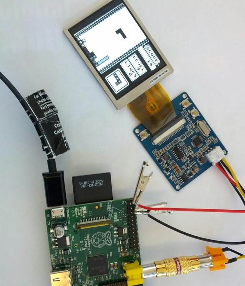
Figure 6-2. Prototype handheld gaming system
The correct thing to tell you is that it’s probably not very stable or a good way to run long-term. The truth is that we played Tetris this way for longer than we’d like to admit, given the number of full-sized modern gaming devices at our disposal. If you don’t want to build in a second power supply, this appears to work out just fine, at least for an afternoon of Tetris.
A better way, however, is to purchase a female DC power adapter. Unscrew the side marked +, insert the red wire, and screw it back down. Insert the black wire on the other side, and you’re set to connect the screen to any power supply with a 2.1 mm DC connection.
Hack 58. Connect Arduino Shields to Your Raspberry Pi
Because there are already many available shields for extending the functionality of an Arduino, Raspberry Pi hackers have found ways to bring those parts to Raspberry Pi.
The idea behind the Raspberry Pi to Arduino shields connection bridge is to allow the Raspberry Pi to make use of any of the shields, boards, and modules designed for Arduino. It also includes the possibility of connecting digital and analog sensors, using the same pinout of Arduino but with the power and capabilities of the Raspberry Pi.
In order to make the compatibility complete, Cooking Hacks created the arduPi library, which allows you to use the Raspberry Pi with the same code used with an Arduino. To do so, they implemented conversion functions so that you can control all the I/O interfaces (I2C, SPI, UART, analog, and digital) in the same way you would control them with the Arduino. Options with this shield and the arduPi library include connecting:
§ Any Arduino wireless module to the Raspberry Pi, such as the XBee 802.15.4/XBee ZigBee, RFID, NFC, Bluetooth, Bluetooth Pro, WiFi, GPRS, or 3G
§ Any sensor (analog 0-5 V, digital) to the Raspberry Pi with a precession of 16b using the integrated ADC.
§ Complex sensors through I2C and UART buses
§ Arduino-specific shields, like the radiation sensor shield, CanBus, and relay shield
§ Any electronic module or actuator that works over I2C, SPI, UART
The bridge board connects to the Raspberry Pi’s GPIO pins from below. As shown in Figure 6-3, the top includes the following items:
§ 8 digital pins
§ Socket for wireless modules
§ RX/TX pins
§ I2C pins (SDA, SCL)
§ SPI pins (SCK, MISO, MOSI, CS), which can be used also as GPIO
§ 8-channel analog-to-digital converter
§ Switch to enable external power supply
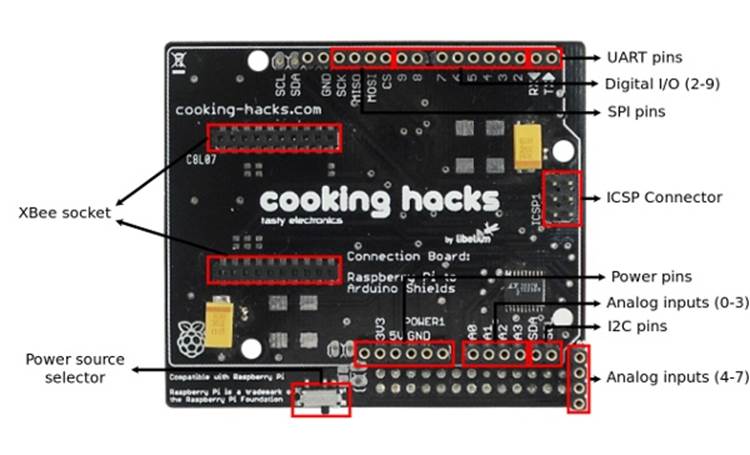
Figure 6-3. Cooking Hacks’ Raspberry Pi to Arduino shields connection bridge
Cooking Hacks includes the schematic as a PDF download on its website.
Using the arduPi Library
arduPi is a C++ library that lets you write programs for Raspberry Pi as if you were writing an Arduino program. All the functions that control serial port communications, I2C, SPI, and GPIO pins are available using the Arduino syntax. The available library functions are listed in Table 6-1.
To get started, first download the arduPi library. In the library folder you will find three files: arduPi.cpp, arduPi.h, and arduPi_template.cpp. The arduPi_template.cpp file is meant to be used as a starting point to create programs with the same behavior as an Arduino program.
Table 6-1. ArduiPi library functions
|
Serial Library functions |
Wire Library functions |
SPI Library functions |
|
available() |
begin() |
begin() |
|
begin() |
requestFrom() |
end() |
|
end() |
beginTransmission() |
setBitOrder() |
|
flush() |
endTransmission() |
setClockDivider() |
|
peek() |
write() |
setDataMode() |
|
print() |
read() |
transfer() |
|
println() |
||
|
read() |
||
|
readBytes() |
||
|
readBytesUntil() |
||
|
find() |
||
|
findUntil() |
||
|
parseInt() |
||
|
parseFloat() |
||
|
setTimeout() |
||
|
write() |
The arduPi template looks like this:
//Include arduPi library
#include "arduPi.h"
/*********************************************************
* IF YOUR ARDUINO CODE HAS OTHER FUNCTIONS APART FROM *
* setup() AND loop() YOU MUST DECLARE THEM HERE *
* *******************************************************/
/**************************
* YOUR ARDUINO CODE HERE *
* ************************/
int main (){
setup();
while(1){
loop();
}
return (0);
}
As you can see in the main() function, the setup() function is called once, and then the loop() function is called continuously until the program is forced to finish.
Whether you’re writing a new program or already have an Arduino program written that uses the ported functions, you can use the template (ardupi_template.cpp) and put your Arduino code where it says YOUR ARDUINO CODE HERE. Remember that the program you are writing is a C++ program, so you can use all the C++ libraries. Here are the available Arduino functions:
§ delay()
§ delayMicroseconds()
§ millis()
§ pinMode()
§ digitalWrite()
§ digitalRead()
§ analogRead() (on pins from A0 to A7—for example, analogRead(5) will read from A5)
§ shiftIn()
§ shiftOut()
§ attachInterrupt()
§ detachInterrupt()
You can detect RISING and FALLING interrupts. Any digital pin (from 2 to 13) can be used in attachInterrupt(). For example, if you want to be aware of RISING events on pin 6, you can use attachInterrupt(6,function_to_call,RISING).
Enable the UART port
On the Raspberry Pi, make a backup of /boot/cmdline.txt and open it for editing:
$ sudo cp /boot/cmdline.txt /boot/cmdline_backup.txt
$ sudo vi /boot/cmdline.txt
Here’s what this file contains:
dwc_otg.lpm_enable=0 console=ttyAMA0,115200 kgdboc=ttyAMA0,115200 console=tty1 $
Remove the parameters that reference the UART serial port (ttyAMA0) so that it says only this:
dwc_otg.lpm_enable=0 console=tty1 $
Open /etc/inittab and comment out the following line:
T0:23:respawn:/sbin/getty -L ttyAMA0 115200 vt100
Then reboot the Raspberry Pi.
Compile the arduPi library and a program using it
As arduPi is a C++ library, we will use g++ to compile it. You can compile the arduPi library to obtain an object file (.o) and use this file to link your program: g++ -c arduPi.cpp -o arduPi.o.
Once you have already compiled the arduPi library, you can run:
$ g++ -lrt -lpthread my_program.cpp arduPi.o -o my_program
If the arduPi library is not yet compiled, you can compile both it and your program and link them in a single step:
$ g++ -lrt -lpthread my_program.cpp arduPi.cpp -o my_program
The -lrt flag is necesary because the library uses the function clock_gettime (time.h). The -lpthread option is needed because attachInterrupt() and detachInterrupt() functions use threads.
Run your program
Now, to run your program, you must have the right permissions in order to use GPIO so that /dev/mem can be accessed on the Raspberry Pi. Then you simply run the following command:
sudo ./my_program
GPIO input
GPIO peripherals vary quite widely. In some cases, they are simple: a group of pins that can be switched as a group to either input or output. The input and output voltages are typically, though not universally, limited to the supply voltage of the device with the GPIOs on and may be damaged by greater voltages.
Some GPIOs have 5 V tolerant inputs, and even on low-supply voltages the device can accept 5 V without damage. For the Raspberry Pi, you must adapt the voltage level of a 5 V sensor to prevent possible damage. If you don’t have an assortment of parts readily available, you can reproduce these instructions with the contents of Cooking Hacks’ Starter Kit for Raspberry Pi, A/V Edition.
GPIO voltage levels are 3.3 V and are not 5 V tolerant. There is no over-voltage protection on the board. Digital inputs use a 3.3 V logic level and are not tolerant of 5 V levels, such as you might find on a 5 V powered Arduino. Use extreme caution when working with GPIO. You might damage your Raspberry Pi or your other equipment and potentially shock yourself.
When a GPIO pin is set as an input, such as with a basic push-button example, you can have these voltage incompatibility problems. The circuit in Figure 6-4 is wrong, because when you press the button, the GPIO input is connected to 5 volts, which might damage the device.

Figure 6-4. Incorrect circuit
You can avoid damage by using a resistor in the push-button cable. The value of the resistor is determined by the leakage current of the GPIO pin (the current used by the circuit to read the pin) and the amount of voltage drop it creates as a result. With the 5K resistor, you obtain 3.3 V in the GPIO input because Vgpio = 5 V·(10K/(10K+5K)) = 3.3 V. Figure 6-5 shows a correct circuit.

Figure 6-5. Correct circuit
You will have the same problem if you use a sensor operating at 5 volts. Figure 6-6 shows an example using a PIR sensor, using the same resistive divider that we used to adapt voltage level.
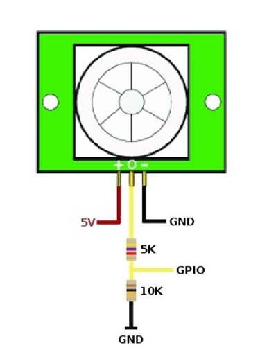
Figure 6-6. Adapting voltage with resistors
Analog-to-Digital Conversion
The shield includes an Analog-to-Digital Converter (ADC) of 12 bits of resolution, which allows you to connect any sensor to the Raspberry Pi with higher precision than an Arduino does. The communication between the Raspberry Pi and the ADC of the shield is made via I2C.
The information of each channel can be obtained reading two bytes from I2C, but first, one byte (corresponding to the channel address) should be sent through I2C, depending on the channel you want to select. Table 6-2 shows a list of the channel addresss.
Table 6-2. Channel addresses
|
Channel |
Address |
|
0 |
0xDC |
|
1 |
0x9C |
|
2 |
0xCC |
|
3 |
0x8C |
|
4 |
0xAC |
|
5 |
0xEC |
|
6 |
0xBC |
|
7 |
0xFC |
The following example program reads every channel continuously, waiting five seconds between iterations. With a wire connecting the 5 V pin with some of the pins of the ADC, it should read a value close to 5.000000:
//Include arduPi library
#include "arduPi.h"
unsigned char val_0 = 0;
unsigned char val_1 = 0;
byte address = 0x08;
int channel_0 = 0;
int channel_1 = 0;
int channel_2 = 0;
int channel_3 = 0;
int channel_4 = 0;
int channel_5 = 0;
int channel_6 = 0;
int channel_7 = 0;
float analog_0 = 0.0;
float analog_1 = 0.0;
float analog_2 = 0.0;
float analog_3 = 0.0;
float analog_4 = 0.0;
float analog_5 = 0.0;
float analog_6 = 0.0;
float analog_7 = 0.0;
void setup()
{
Wire.begin(); // join I2C bus (address optional for master)
}
void loop()
{
// channel 0
Wire.beginTransmission(8);
Wire.write(byte(0xDC));
char val[2];
val_0 = Wire.read(); // receive high byte (overwrites previous reading)
val_1 = Wire.read();
channel_0 = int(val_0)*16 + int(val_1>>4);
analog_0 = channel_0 * 5.0 / 4095.0;
printf("Channel 0: digital value = %d", channel_0);
printf(" analog value = %f\n", analog_0);
// channel 1
Wire.beginTransmission(8);
Wire.write(byte(0x9C));
val_0 = Wire.read(); // receive high byte (overwrites previous reading)
val_1 = Wire.read();
channel_1 = int(val_0)*16 + int(val_1>>4);
analog_1 = channel_1 * 5.0 / 4095.0;
printf("Channel 1: digital value = %d", channel_1);
printf(" analog value = %f\n", analog_1);
// channel 2
Wire.beginTransmission(8);
Wire.write(byte(0xCC));
val_0 = Wire.read(); // receive high byte (overwrites previous reading)
val_1 = Wire.read();
channel_2 = int(val_0)*16 + int(val_1>>4);
analog_2 = channel_2 * 5.0 / 4095.0;
printf("Channel 2: digital value = %d", channel_2);
printf(" analog value = %f\n", analog_2);
// channel 3
Wire.beginTransmission(8);
Wire.write(byte(0x8C));
val_0 = Wire.read(); // receive high byte (overwrites previous reading)
val_1 = Wire.read();
channel_3 = int(val_0)*16 + int(val_1>>4);
analog_3 = channel_3 * 5.0 / 4095.0;
printf("Channel 3: digital value = %d", channel_3);
printf(" analog value = %f\n", analog_3);
// channel 4
Wire.beginTransmission(8);
Wire.write(byte(0xAC));
val_0 = Wire.read(); // receive high byte (overwrites previous reading)
val_1 = Wire.read();
channel_4 = int(val_0)*16 + int(val_1>>4);
analog_4 = channel_4 * 5.0 / 4095.0;
printf("Channel 4: digital value = %d", channel_4);
printf(" analog value = %f\n", analog_4);
// channel 5
Wire.beginTransmission(8);
Wire.write(byte(0xEC));
val_0 = Wire.read(); // receive high byte (overwrites previous reading)
val_1 = Wire.read();
channel_5 = int(val_0)*16 + int(val_1>>4);
analog_5 = channel_5 * 5.0 / 4095.0;
printf("Channel 5: digital value = %d", channel_5);
printf(" analog value = %f\n", analog_5);
// channel 6
Wire.beginTransmission(8);
Wire.write(byte(0xBC));
val_0 = Wire.read(); // receive high byte (overwrites previous reading)
val_1 = Wire.read();
channel_6 = int(val_0)*16 + int(val_1>>4);
analog_6 = channel_6 * 5.0 / 4095.0;
printf("Channel 6: digital value = %d", channel_6);
printf(" analog value = %f\n", analog_6);
// channel 7
Wire.beginTransmission(8);
Wire.write(byte(0xFC));
val_0 = Wire.read(); // receive high byte (overwrites previous reading)
val_1 = Wire.read();
channel_7 = int(val_0)*16 + int(val_1>>4);
analog_7 = channel_7 * 5.0 / 4095.0;
printf("Channel 7: digital value = %d", channel_7);
printf(" analog value = %f\n", analog_7);
printf("\n");
delay(1000);
}
int main (){
setup();
while(1){
loop();
}
return (0);
}
Figure 6-7 shows the output of this program when connecting the 5 V pin of the Raspberry Pi to the analog input 0.
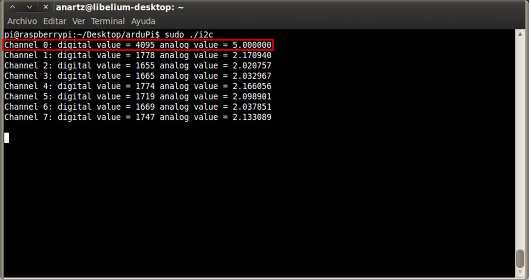
Figure 6-7. Output of ADC program
UART
Accessing UART with the arduPi library is as simple as doing it with Arduino. You need to include arduPi.h in your code and create an instance of the SerialPi class, naming it Serial. Naming the instance as Serial allows you to use the Arduino syntax.
These steps are already done for you if you use the template to create your programs.
These are the available functions:
§ Serial.available()
§ Serial.begin()
§ Serial.end()
§ Serial.flush()
§ Serial.peek()
§ Serial.print()
§ Serial.println()
§ Serial.read()
§ Serial.readBytes()
§ Serial.readBytesUntil()
§ Serial.find()
§ Serial.findUntil()
§ Serial.parseInt()
§ Serial.parseFloat()
§ Serial.setTimeout()
§ Serial.write()
All of these functions have the same functionality as their Arduino counterparts, which you can read more about at http://arduino.cc/en/Reference/serial.
I2C
Analog-to-Digital Conversion briefly discussed I2C. This example in this section uses a BlinkM RGB I2C-controlled LED. BlinkM (Figure 6-8) has a high-quality, high-power RGB LED and a small AVR microcontroller in one piece, allowing a user to digitally control an RGB LED over a simple I2C interface. In this example, you’ll change the LED color both directly and using fade transitions.

Figure 6-8. blinkM module
More information about this part and the commands you can send to it can be found in the BlinkM datasheet.
To set up Blink FM, make the following connections:
1. Connect the (-) pin of the LED with the GND pin of the shield.
2. Connect the (+) pin of the LED with the 5V pin of the shield.
3. Connect the d pin of the LED with the SDA pin of the shield.
4. Connect the c pin of the LED with the SCL pin of the shield.
Then create and execute a file with the following code, which will alternate the LED’s color from red to blue five times and then make some smooth transitions resulting in purples:
*
* Copyright (C) 2012 Libelium Comunicaciones Distribuidas S.L.
* http://www.libelium.com
*
* This program is free software: you can redistribute it and/or modify
* it under the terms of the GNU General Public License as published by
* the Free Software Foundation, either version 3 of the License, or
* (at your option) any later version.
*
* This program is distributed in the hope that it will be useful,
* but WITHOUT ANY WARRANTY; without even the implied warranty of
* MERCHANTABILITY or FITNESS FOR A PARTICULAR PURPOSE. See the
* GNU General Public License for more details.
*
* You should have received a copy of the GNU General Public License
* along with this program. If not, see .
*
* Version 0.1
* Author: Anartz Nuin Jiménez
*/
//Include arduPi library
#include "arduPi.h"
void setup(){
Wire.begin();
Wire.beginTransmission(9);
Wire.write('o'); //End the current Light script
Wire.endTransmission();
}
void loop(){
for (int i=0;i < 5;i++){
Wire.beginTransmission(9);
Wire.write('n'); //Change to color
Wire.write(byte(0xff)); //Red component
Wire.write(byte(0x00)); //Green component
Wire.write(byte(0x00)); //Blue component
Wire.endTransmission();
delay(500);
Wire.beginTransmission(9);
Wire.write('n'); //Change to color
Wire.write(byte(0x00)); //Red component
Wire.write(byte(0x00)); //Green component
Wire.write(byte(0xff)); //Blue component
Wire.endTransmission();
delay(500);
}
for (int i=0;i < 10;i++){
Wire.beginTransmission(9);
Wire.write('c'); //Fade to color
Wire.write(byte(0xff)); //Red component
Wire.write(byte(0x00)); //Green component
Wire.write(byte(0x5a)); //Blue component
Wire.endTransmission();
delay(150);
Wire.beginTransmission(9);
Wire.write('c'); //Fade to color
Wire.write(byte(0x55)); //Red component
Wire.write(byte(0x20)); //Green component
Wire.write(byte(0x5a)); //Blue component
Wire.endTransmission();
delay(150);
}
}
int main (){
setup();
while(1){
loop();
}
return (0);
}
SPI
It is possible to communicate with SPI devices using the functions provided by arduPi. The following example uses the SPI functions to print messages on a ST7920 LCD12864 (SPI LCD).
First put the switch of the LCD in SPI mode. Then proceed with the connection between the LCD and the Raspberry Pi to Arduino shield. Use jumper wires to connect the following, as shown in Figure 6-9:
§ VCC of the LCD to 5 V of the shield
§ GND of the LCD to GND of the shield
§ SCK of the LCD to SCK of the shield
§ SID of the LCD to MOSI of the shield
§ CS of the LCD to 8 pin of the shield
|
|
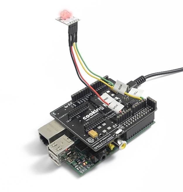
Figure 6-9. LCD shield
For this project, we are using GPIO pin 8 on the Raspberry Pi shield as chip select. So, when you need to select the LCD as the target device for the SPI communication, you need to set pin 8 to HIGH.
Create and execute a file with the following code to show the messages “Cooking Hacks” and “SPI LCD for Raspberry Pi” with a delay of two seconds in between:
/*
* Copyright (C) 2012 Libelium Comunicaciones Distribuidas S.L.
* http://www.libelium.com
*
* This program is free software: you can redistribute it and/or modify
* it under the terms of the GNU General Public License as published by
* the Free Software Foundation, either version 3 of the License, or
* (at your option) any later version.
*
* This program is distributed in the hope that it will be useful,
* but WITHOUT ANY WARRANTY; without even the implied warranty of
* MERCHANTABILITY or FITNESS FOR A PARTICULAR PURPOSE. See the
* GNU General Public License for more details.
*
* You should have received a copy of the GNU General Public License
* along with this program. If not, see .
*
* Version 0.1
* Author: Anartz Nuin Jiménez
*/
//Include arduPi library
#include "arduPi.h"
int latchPin = 8;
unsigned char char1[]=" Cooking Hacks ";
unsigned char char2[]=" SPI LCD for ";
unsigned char char3[]=" Raspberry Pi ";
void initialise();
void displayString(int X,int Y,unsigned char *ptr,int dat);
void writeCommand(int CMD);
void writeData(int CMD);
void writeByte(int dat);
void clear();
void setup(){
SPI.begin();
SPI.setBitOrder(MSBFIRST);
SPI.setDataMode(SPI_MODE0);
SPI.setClockDivider(SPI_CLOCK_DIV128);
initialise();
}
void loop(){
displayString(0,0,char1,16);
delay(2000);
clear();
displayString(1,0,char2,16);
displayString(2,0,char3,16);
delay(2000);
clear();
}
void initialise(){
pinMode(latchPin, OUTPUT);
digitalWrite(latchPin, LOW);
delayMicroseconds(80);
writeCommand(0x30);
writeCommand(0x0c);
writeCommand(0x01);
writeCommand(0x06);
}
void displayString(int X,int Y,unsigned char *ptr,int dat){
int i;
switch(X){
case 0: Y|=0x80;break;
case 1: Y|=0x90;break;
case 2: Y|=0x88;break;
case 3: Y|=0x98;break;
default: break;
}
writeCommand(Y);
for(i=0;i < dat;i++){
writeData(ptr[i]);
}
}
void writeCommand(int CMD){
int H_data,L_data;
H_data = CMD;
H_data &= 0xf0;
L_data = CMD;
L_data &= 0x0f;
L_data <<= 4;
writeByte(0xf8);
writeByte(H_data);
writeByte(L_data);
}
void writeData(int CMD){
int H_data,L_data;
H_data = CMD;
H_data &= 0xf0;
L_data = CMD;
L_data &= 0x0f;
L_data <<= 4;
writeByte(0xfa);
writeByte(H_data);
writeByte(L_data);
}
void writeByte(int dat){
digitalWrite(latchPin, HIGH);
delayMicroseconds(80);
SPI.transfer(dat);
digitalWrite(latchPin, LOW);
}
void clear(){
writeCommand(0x30);
writeCommand(0x01);
}
int main (){
setup();
while(1){
loop();
}
return (0);
}
You can find further support and forums and purchase shields and sensors that work with these instructions.
If you’re interested in further pursuing Raspberry Pi projects that integrate Arduino parts, you might also be interested in the Alamode (shown in Figure 6-10), a development board that, like the Cooking Hacks board, makes your Raspberry Pi compatible with Arduino shields. The Alamode is voltage-safe, it has a built-in, bi-directional translator that makes the 3.3 V to 5 V conversion for you, and it also has a Micro-SD slot for storage and an RTC chip.
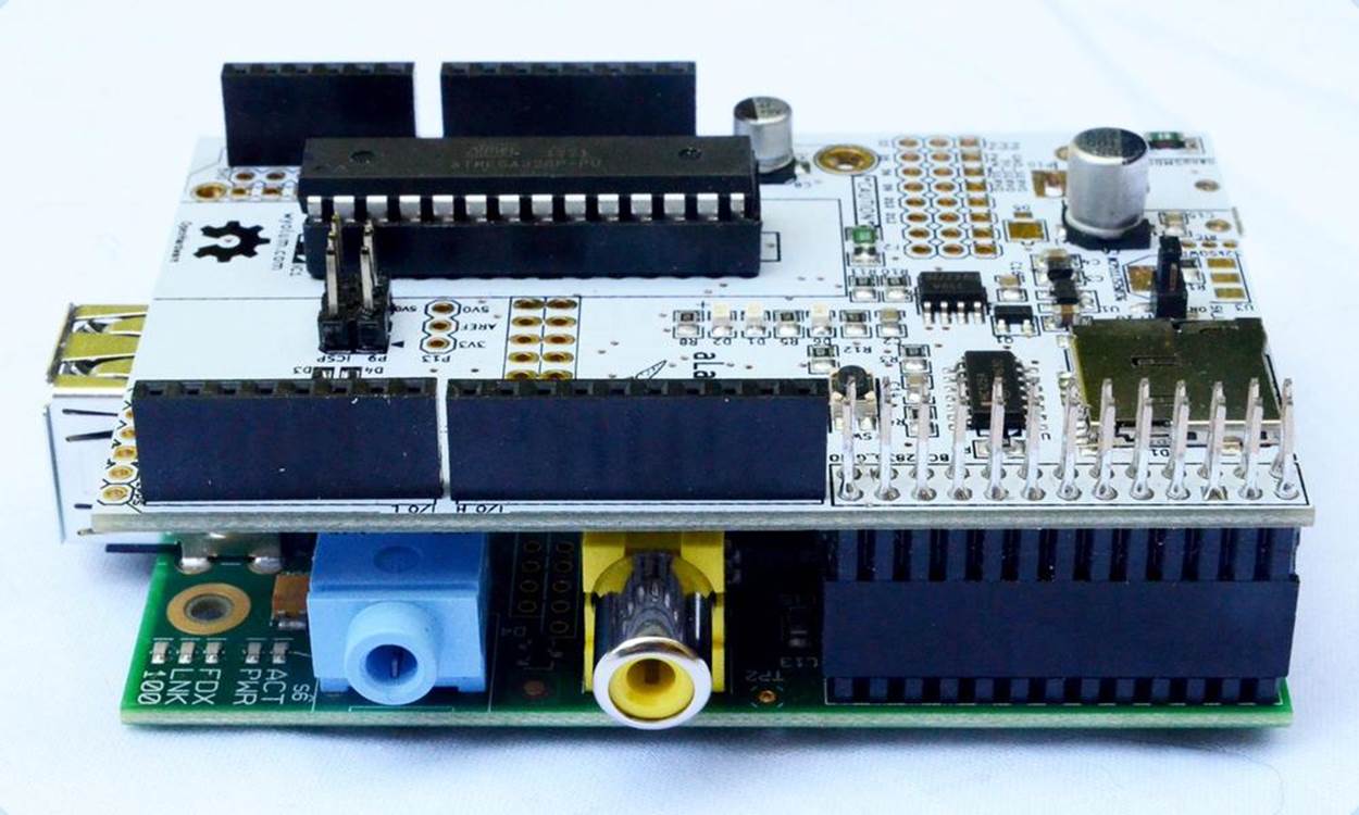
Figure 6-10. Alamode board sitting on Raspberry Pi, showing GPIO connection
Although the Cooking Hacks Raspberry Pi to Arduino board and the Alamode are not identical, you might end up making a decision based partly on features and partly on which you find easier and more convenient to obtain based on where in the world you live. Cooking Hacks is based in Spain but has global distributors. In the United States, look to MicroController Pros for their products. You can buy the Alamode here, which has an American warehouse and distributors around the world.
—David Bordonada
Hack 59. Control a 3D Printer
Home 3D printing is a relatively new possibility for most people, but as prices for printers continue to drop, you might find yourself happily printing plastic. Why not let your Raspberry Pi help?
A 3D printer is an amazing machine that lets you convert a 3D model that exists only in bits and bytes into something tangible. Until recently, the cost for this hardware was prohibitively high, both in price and space required to house it. In the last few years, however, they’ve gone from tens (or hundreds) of thousands of dollars to as little as a few hundred and from the size of a refrigerator to smaller than your toaster.
These increasingly common home 3D printers use an additive method, which means plastic (or other malleable materials) are driven through a heated extruder. This extruder is attached to a series of belts and motors, which allow it to move along the X, Y, and Z axes. The plastic is then extruded in layers onto a plate of glass (which may or may not be heated, depending on the plastic type in use), where it cools quickly. The printer repeats this process, printing layer upon layer (upward) until the object is completed.
There are many different types of these 3D printers, but the most common is known as the RepRap family of printers. These printers feature open hardware and are relatively easy to build from publicly available plans on the Internet, but they are also available in prebuilt commercial offerings. One such vendor is Lulzbot, which produces and sells high-quality (and high-resolution) RepRap style printers.
For the purposes of this hack, we’ll assume that you have a Lulzbot AO-101 (shown in Figure 6-11), but these instructions apply generally to any printer in the RepRap family.
Figure 6-11. Tom’s Lulzbot AO-101
The Lulzbot AO-101 is powered by a RAMBo electronics board (Figure 6-12), which uses an Atmega processor, stepper motor drivers, and power management outputs to control the movement and temperature of the extruder and the heated plate glass bed. While this hardware does its job very well, it is not very smart. It knows only how to process a series of instructions called G-code.
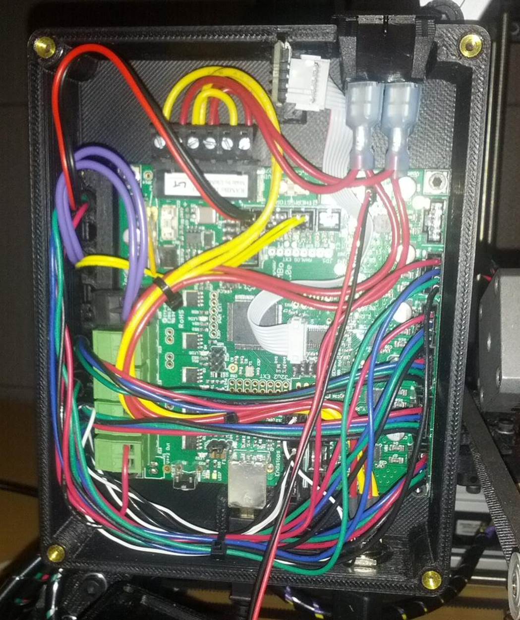
Figure 6-12. RAMBo electronics in Lulzbot AO-101
G-code is a computer language that tells the 3D printer exactly what to do, through a series of explicit instructions. It tells the printer where to move its extruder and bed, at what speeds, and through what paths. It is roughly analogous to PostScript for traditional 2D printers.
G-code has existed since the 1950s and is generally accepted as the standard language for interfacing with computerized machine tools. However, because each 3D printer is different, you cannot simply take a G-code file and send it to any printer. The G-code has to be generated with the specifications of your printer taken into account.
REPLACE THE RAMBO WITH A RASPBERRY PI?
You might wonder why we don’t talk about replacing the RAMBo electronics with the Raspberry Pi. While the Raspberry Pi is a lot smarter than the RAMBo board and is capable of sending instructions to the 3D printer and manipulating and “slicing” models into G-code, the RAMBo board is specialized for performing real-time control of the stepper motors (and heating units) that make up the heart of the 3D printer. The Raspberry Pi would be a poor substitute for this without extensive (and complicated) modifications. Even when hacking, we prefer to let the Raspberry Pi and the RAMBo live in harmony, taking advantage of each other’s strengths.
Using a 3D printer from Linux is a multiple-stage process. First, you need to have a 3D model that you want to print. This could be something that you built yourself using free software like Blender or OpenSCAD, or it could be something you downloaded off the Internet. Thingiverse is dedicated to the sharing of user-designed files for 3D models, and it’s a great starting point if you’re looking for something to print.
Once you’ve got a 3D model that you want to print, the next step is to convert that model into the G-code for your printer. There are several available software packages that do this, but our favorite is Slic3r.
On Pidora, slic3r is packaged up, so you can install it with yum:
$ sudo yum install slic3r
On other distributions, you’ll need to download and install slic3r from source:
$ git clone git://github.com/alexrj/Slic3r
$ cd Slic3r
$ sudo perl Build.PL
$ sudo perl Build.PL --gui
Once slic3r is installed, you can run it in GUI mode. It will prompt you to configure your printer. The Lulzbot website includes slic3r configuration files for their printers.
Add your 3D model to slic3r (scaling and copying as desired), then click the Export G-code button. This is a resource intensive process, so it will take quite a bit longer on your Raspberry Pi than it would on your laptop, but it will eventually complete.
When you have your .gcode file, you’ll need to send it to the printer to print. The recommended printer control software for the Lulzbot AO-101 is called Printrun. Printrun is a set of Python applications for sending G-code instructions to the printer, including the instructions to print your 3D model, but also for moving the printer around and controlling the heated units.
On Pidora, Printrun is packaged up, so to install it, just run:
$ sudo yum install printrun
On other distributions, you’ll have to download the Printrun source code from GitHub:
$ git clone https://github.com/kliment/Printrun.git
The Printrun source is Python, so no compilation is needed. To run the GUI interface for printrun (pronterface), simply run:
$ sudo ./pronterface.py
PRONTERFACE NAMING
Did we say pronterface? Yes, we did. It isn’t a typo. That’s just what printrun calls their GUI application. The name is derived from their console utility, pronsole. The name looks funny, but the GUI works well.
This will open a wxPython GUI interface. You will need to configure it to connect to the 3D printer (plugged into the Raspberry Pi via USB). The Lulzbot AO-101 looks like a USB serial device, so you will tell Printrun to connect to the /dev/ttyACM0 port.
Make sure the port baud rate is set to 115200 in the pull-down menu to the right of the port selection. Then hit the connect button, and the 3D printer (assuming it is turned on) will connect and send a status message. You can then load up the .gcode file for your 3D model.
You will need to turn on the heated nozzle and bed to the proper temperatures for the type of plastic that is loaded into your printer (these buttons are in the lower left of the UI interface). Once the printer is at the proper heat settings, you click the Print button, and off it goes!
Hack 60. Add a Numeric Keypad
Thanks to the ubiquity of telephones and automatic teller machines, most people alive today are intimately familiar with a numeric keypad. Hacking one into your Raspberry Pi can open up a wide range of possible projects.
A numeric keypad doesn’t seem like much—just a 3 x 4 grid of numbers and symbols (occasionally a 4 x 4 grid), right? And everyone who has ever dialed (a humorous leftover term, given that we’re talking about keypads rather than rotary dials) a phone number or entered a PIN for an ATM withdrawal or debit purchase knows how to use it. But added to a Raspberry Pi, you could use a keypad as part of a locking mechanism or for any kind of numeric input. You could even use it to turn your Raspberry Pi into a Voice over IP (VoIP) phone, but with that old push-button feel.
In addition to your Pi, you’ll need:
§ Linux preinstalled with python2 (any distribution should work).
§ A matrix input numeric keypad. We used the Membrane 3x4 Matrix Keypad available from Adafruit, but you can adjust our instructions to work with other keypads.
§ A breadboard and male-to-female jumper wires. These are just for prototyping the numeric keypad connection to the GPIO on the Raspberry Pi. For a more permanent setup, you should solder things together.
These instructions assume you’re using a Raspberry Pi Model B, revision 2. If you’re not, the GPIO pin numbers are different, and you’ll need to adjust.
How the Matrix Keypad Works
The Membrane 3x4 Matrix Numeric Keypad is simple. It has three columns with four rows of buttons and one wire for each row and column, as shown in Figure 6-13.
|
|

Figure 6-13. Membrane 3 x 4 Matrix Numeric Keypad
The wires from the numeric keypad run to seven pins (pins 1 and 7 are labeled). Use the jumper wires to connect these pins into your breadboard. By scanning the activity of the rows and columns, you can detect which button is being pressed on the keypad and translate it to the corresponding number.
The ordering of the pins might be logical from a layout perspective, but it took us a bit of trial and error to determine which rows and columns matched up to the keypad pins. See Table 6-3 for reference.
Table 6-3. Keypad pins and associated rows/columns
|
Keypad Pin Number |
Row/Column |
|
7 |
Row 1 |
|
6 |
Row 2 |
|
5 |
Row 3 |
|
4 |
Row 4 |
|
3 |
Column 1 |
|
2 |
Column 2 |
|
1 |
Column 3 |
Obviously, if you’re using a different numeric keypad, your pinouts may differ.
Connecting the Keypad to the Raspberry Pi
The simplest way to connect the numeric keypad to the Raspberry Pi is to connect each of the keypad pins to a dedicated GPIO pin. The code in this hack assumes that you have the pins connected as shown in Table 6-4.
Table 6-4. Keypad pins to GPIP pins
|
Keypad Pin Number |
Row/Column |
GPIO Pin |
|
7 |
Row 1 |
18 |
|
6 |
Row 2 |
23 |
|
5 |
Row 3 |
24 |
|
4 |
Row 4 |
25 |
|
3 |
Column 1 |
4 |
|
2 |
Column 2 |
17 |
|
1 |
Column 3 |
22 |
The simplest way to wire this is by connecting the female end of a jumper wire to a GPIO pin, then connecting the male end of that wire into the appropriate location on the breadboard. Remember, you want to have the GPIO-connected jumper wires lined up with the corresponding horizontal row that contains the keypad pin.
HOW TO USE FEWER PINS
This configuration is the easiest to wire, but it does have the disadvantage of using up a lot of the GPIO pins on your Raspberry Pi. If you are feeling braver, you could cut back on the number of GPIO pins used by wiring a demultiplexer (demux) to the row pins, cutting them from four down to two.
You could also binary encode the column outputs with pull-down resistors on the GPIO input pins and diodes to generate and mix the binary signal, resulting in two column pins instead of three. If you do this, you’d need to write new code to handle the more complicated inputs, which is left as an exercise to the power hacker. (Credit goes to aTao on the Raspberry Pi forums for pointing this out.)
Installing the Software
To keep things simple here, we’ll take advantage of the Python Raspberry Pi GPIO library. Pidora and Raspbian install this software by default, but if you do not have it already available in your Linux distribution, you can download the source code. A copy of this code is also included in the GitHub repository for this book.
Chris Crumpacker wrote a Python library called matrix_keypad to interface the Raspberry Pi directly with the Adafruit Matrix numeric keypad, but unfortunately, it has some bugs which prevent it from working as is. We’ve taken revision 1.0.4 of his library and cleaned up the bugs that were preventing it from working properly.
To install this library, first check out the fixed source code:
$ git clone https://github.com/spotrh/rpihacks
$ cd rpihacks/matrix_keypad-1.0.4-fixed
Next, build and install the fixed library:
$ python setup.py build
$ su -c 'python setup.py install --prefix=/usr'
Running the Program
Now you have a working copy of the matrix_keypad library installed on your Raspberry Pi. We have also included a demonstration script (derived from Chris’s examples) so that you can test your setup. There is a file in the matrix_keypad-1.0.4-fixed/ directory called book-demo.py. Make sure your numeric keypad is wired in correctly, then run:
$ chmod +x book-demo.py
$ su -c './book-demo.py'
This code will prompt you to enter your four-digit secret code into the numeric keypad. The code in this example is 8675. As you enter the digits, it will print out debugging details showing you the digit entered, the current stored value of your code to that point, the number of digits in your code that you have entered, and finally, after four digits have been entered, whether your code is correct.
Nifty, huh? But how does it work? book-demo.py uses the keypad function from the matrix_keypad_RPi_GPIO module in the matrix_keypad library. The matrix_keypad_MCP230xx module in the library it is only for when you have an I2C Port Expander in use. The code also imports the sleep and exit functions from the standard Python time and sys libraries so the code can sleep briefly if it’s entered incorrectly and so that it can exit if it is entered properly:
from matrix_keypad.matrix_keypad_RPi_GPIO import keypad
from time import sleep
from sys import exit
Now, to silence the GPIO warnings. The Python Raspberry Pi GPIO library emits warnings whenever you have any GPIO pins configured as anything other than input. Since the matrix_keypad_RPi_GPIO library always configures the column pins as output (low), you’ll get this warning every time you use it. You don’t want to see that, so silence it by disabling the warnings:
import RPi.GPIO as GPIO
GPIO.setwarnings(False)
Now you need to initialize the keypad class from the matrix_keypad_RPi_GPIO module. This will create a kp variable you can use to read the keys from the physical numeric keypad. The matrix_keypad_Rpi_GPIO module supports both 3 x 4 and 4 x 4 numeric keypad devices, but because our hardware is a 3 x 4, we’ll tell it that we have only three columns. We also set up variables to store code attempts, the passcode we are checking for, and a counter variable to track the progress of inputting the code:
kp = keypad(columnCount = 3)
# Setup variables
attempt = "0000"
passcode = "8675"
counter = 0
At this point, the program prints a friendly message to the user to tell her what to do (input the four-digit secret code) and start a loop:
print 'Enter your four digit secret code into the numeric keypad!'
# Loop while waiting for a keypress
while True:
# Loop to get a pressed digit
digit = None
while digit == None:
digit = kp.getKey()
The loop uses the getKey() function from the keypad class to continuously poll the numeric keypad device waiting for the user to press keys and input parts of her code. Once a key is pressed, the value of digit changes from None to the value of the key pressed, the value of the digit entered prints, the value for the code to that point (in the attempt variable) updates, and the code entered so far prints:
# Print the result
print "Digit Entered: %s"%digit
attempt = (attempt[1:] + str(digit))
print "Attempt value: %s"%attempt
Now the program checks to see if the code as entered so far matches the value set in passcode earlier. If it does, the program prints a happy message and exits:
# Check for passcode match
if (attempt == passcode):
print "Your code was correct, goodbye."
exit()
If it doesn’t match the passcode (either because it is incorrect or because not enough digits have been entered), the program proceeds to the end of the loop, updating the number of digits entered. If the number of digits in the entered code is more than four, the program knows the user did not find the correct code in time it restarts the loop. If it is fewer than four digits, it simply loops again and waits for more digits:
else:
counter += 1
print "Entered digit count: %s"%counter
if (counter >= 4):
print "Incorrect code!"
sleep(3)
print "Try Again"
sleep(1)
counter = 0
sleep(0.5)
This example program plays a simple guessing game, but it illustrates how you can use the physical numeric keypad as an input device. You could easily modify this code to unlock a door when the correct code is entered, incorporate it as part of an alarm system, or use it to take numeric input for a Raspberry Pi-controlled thermostat.
Hack 61. Add a Heat Sink
A heat sink for your Raspberry Pi? But it’s so little! Tiny, but mighty. You may be surprised at just how warm it can get.
You’ve probably noticed that computers are hot. Not like “don’t touch the stove” hot (most of the time), but “my smartphone is sometimes a hand warmer in the winter” hot. It’s the integrated circuits (ICs) that make that toasty feeling (as well as make your electronics work), and assorted bad things happen when they get too toasty, ranging from warping the plastic case to (in extreme cases) burning laps of people who take “laptop” literally. Sometimes you’ll learn your computer is too hot because it knows it’s overheating and locks up or shuts down. It’s unlikely your Raspberry Pi will overheat in average use, but it’s not impossible with more intense use.
A heat sink could seem like a bit much for such a little device, but depending on what you’re using the Pi for (have you read [Hack #6]?), it could extend the computer’s life. And frankly, heat sinks look neat. Of course, if your goal is “as small as possible,” this isn’t the plan for you. If your goal is “naked electronics looking awesome,” you’re in the right place.
NOT SAFE FOR KIDS?
The Raspberry Pi was designed for education, and that includes with safety in mind. It’s exceptionally unlikely that in any normal use, the Pi is going to get so hot as to be unsafe to touch, so don’t worry about giving it to your kids.
The Raspberry Pi produces heat from three ICs: the CPU, the Ethernet controller, and the power regulator. Geektopia used a thermal camera to study the Raspberry Pi’s heat output (as shown in Figure 6-14. Simply plugged in and running, the three ICs had measured temperatures of, 48.7º C (119.66º F), 53º C (127.4º F), and 49.9º C (121.82º F), respectively.
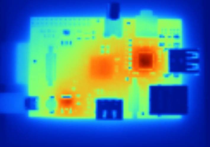
Figure 6-14. Thermal photo of Raspberry Pi running but at rest (courtesy of GeekTopia, http://www.geektopia.es)
The hottest test Geektopia ran was during video playback with Ethernet plugged in, which drove the Ethernet controller to 65.1º C (149.18º F). (The full test results are available in Spanish.) You can read one method of measuring your own CPU’s temperature inMeasure Temperature.
Which heat sink you buy depends not only on your performance needs, but potentially on your aesthetic preferences and shipping location. Barch Designs sells a Raspberry Pi case made from CNC-milled aircraft-grade aluminum that also acts as a heat sink. The case gives you access to all the ports and has visibility to the LEDs with engraving showing their purposes. As a bonus, you can have it etched with your words or design—perhaps the name of your project?
The Barch Design case (shown in Figure 6-15) comes with a thermal paste. The interior of the case has three raised pillars that contact the three IC chips on the Raspberry Pi. Apply the paste to each of these pillars to activate the heat sink properties of the case.

Figure 6-15. Heat sink case (photo by Benjamin Barch)
Because we’re based in the United States, we refer frequently in this book to parts available from Adafruit, but if you’re not in North America, ModMyPi, a UK-based company that sells Raspberry Pi accessories and parts, might be a better bet for a lot of your needs. They deliver internationally with an expected wait of three to seven days, which isn’t bad if they have something you can’t find anywhere else.
ModMyPi sells a more traditional-looking set of alumnium heat sinks with a small piece for each of the three heat-producing areas. No glue required for this one—they attach with provided thermal tape.
A heat sink alone won’t change everything, though. If you have it sealed up inside a case (other than ones like that above designed to be or complement a heat sink), you’re just sending the heat a few extra centimeters away—not that useful. Make sure your chosen housing has appropriate air circulation.
Hack 62. Enable the Raspberry Pi Camera on Pidora
As of this writing, the Raspbery Pi camera module does not yet officially work with Pidora. That doesn’t mean we can’t make it happen anyway.
Using the Raspberry Pi camera module is well-documented online—if you’re using Raspbian. To do so, you need to update the OS and use the built-in raspi-config tool to enable it. There are a few more steps, but that’s the gist of it. Pidora doesn’t use raspi-config, though, so it takes another step or two, but you can still use the camera module with it.
Mount the SD card in your laptop or other computer that isn’t the Raspberry Pi. Mount the two partitions, replacing /dev/mmcblk0 with the location of your own SD card, which you can find with df -h:
$ sudo mnt /dev/mmcblk0p1 /mnt/raspi-boot/
$ sudo mnt /dev/mmcblk0p2 /mnt/raspi-root/
Then update all the boot firmware from the Pidora image to the latest version from GitHub and copy the firmware onto the SD card:
$ git clone https://github.com/raspberrypi/firmware
$ cp -a firmware/boot/*.bin firmware/boot/*.dat firmware/boot/*.elf /mnt/raspi-boot/
Update the videocore libraries and binaries. With the Pidora SD card mounted, run:
$ sudo cp -a firmware/hardfp/opt/vc/bin /mnt/raspi-root/usr/
$ sudo cp -a firmware/hardfp/opt/vc/include /mnt/raspi-root/usr/
$ sudo cp -a firmware/hardfp/opt/vc/lib /mnt/raspi-root/usr/
$ sudo cp -a firmware/hardfp/opt/vc/sbin /mnt/raspi-root/usr/
Finally, add these two lines to /boot/config.txt on the SD card:
gpu_mem=128
start_x=1
As mentioned previously, the camera needs 128 MB of memory dedicated to the GPU to work correctly. The _x firmware variant is the one that the Pi needs to use the camera.
Shut down and connect the camera to the Raspberry Pi. The blue tape side of the ribbon cable should be facing toward the Ethernet jack, and the leads side should be facing toward the HDMI connector. Make sure none of the lead pins are bent.
Start the Pi, and you’re ready to test the connection:
sudo raspistill -v -o temp.jpg
Of course, before performing that last step, you should be sure to slyly point it at family members doing something hilarious. That camera’s so small, they’ll never notice.
Hack 63. Build a Solar-Powered Lab
One of the benefits of the Pi is its low-power consumption, which makes it well suited to being the centerpiece of a solar-powered education lab.
Several rural labs around the world have taken advantage of RACHEL. Short for remote area community hotspots for education and learning, RACHEL deployments are low-cost, scalable collections of open source software and educational content pulled from Creative Commons licensed sources such as The Khan Academy, Wikipedia, and CK-12.
RACHEL servers are specifically intended for remote locations with low-to-no Internet connectivity. Powering Potential uses the RACHEL educational software on the server that is then accessed through each student’s unit. RACHEL is free to download, install, manage, and replicate and can be deployed in nearly any environment with minimal hardware, such as a Raspberry Pi lab.
In fact, one of the configurations available from RACHEL is designed specifically for the Raspberry Pi and called RACHEL-Pi. It’s been used by The Best of Both initiative in Ghana and Powering Potential in Tanzania. Powering Potential also uses solar power to run the labs. Thanks to a low-power monitor and the Pi, each workstation consumes less than 10 watts over DC power.
Powering Potential’s flagship program, Educating-Through-Technology, partners with government secondary schools in Tanzania to bring the Raspberry Pi and basic technology instruction to students. In 2013, they began rolling the program out to three schools in each of Tanzania’s 30 regions.
Unlike many of the hacks in this book, these workstations require a Model B, revision 2 with 512 MB of RAM. (And because it is for educational purposes, Powering Potential houses the Pis in clear cases so that the students can see the components.) You’ll also need a 4 GB or greater SD card, and they recommend a Class 10 or UHS-1 (Ultra High Speed) card (see Class 10 Too Classy? for notes on this).
Gather Hardware
For each station, the Raspberry Pis in their cases are mounted on the back of each monitor. Each workstation includes:
§ Hanns-G Model Hl161Abb 15.6” LED monitor. This choice is part of a goal to obtain low-wattage equipment that consumes only 10 watts of electricity between the monitor and the computer (and running on DC instead of AC power).
§ Pi View HDMI to VGA Adapter.
§ Keyboard, mouse, router, printer, and modem (for their work, Powering Potential sources these locally in Tanzania).
§ Wi-Pi USB Wireless Adapter (originally used for communication between the student client and the servers, but due to intermittent connection issues, Powering Potential is exploring replacement solutions).
§ Powered USB hub (optional).
§ 12-volt-to-5-volt stepdown converter 3 A female USB (Figure 6-16), which is used to connect the Raspberry Pi to the 12 V solar power system, in addition to the Micro USB cable to power to Raspberry Pi.
§ Headsets for sound.

Figure 6-16. 12-volt-to-5-volt stepdown converter
For the solar power system for the lab, they use a vendor configuration from Ensol Tanzania Limited, which includes:
§ 85 W solar module
§ 108 Ah solar battery
§ 45 A solar controller
§ Mounting frame
§ Battery box
§ 180 watt DC-to-AC inverter (for printer)
§ Lightning arrestor and earthing system
The hardware required for the RACHEL server is identical to the client/student configuration, except that it requires a larger SD card—32 GB for only RACHEL-Pi or 64 GB if KA-Lite is included. Because 64 GB cards are not well-suited to the purpose, only cards rated UHS-1 will work for that scenario. In addition, a router facilitates communication between student clients and the servers. The UHS-1 class 64 GB cards that have been tested and known to work with the Pi include:
§ Kingston SD10G3/64GB UHS-I Elite
§ Lexar Platinum II SDXC UHS-I Card
§ SanDisk Ultra® SDXC™ UHS-I
Set Up the Raspberry Pi
Powering Potential uses Raspbian for the student Raspberry Pis. Emmanuel Ackerman, technical adviser at Powering Potential, offers configuration tips on the WorldPossible forums under the handle mannyack.
Most importantly, he notes that the default sound configuration is “auto,” which means that if you connect the monitor through the composite video port, the sound will be directed through the audio jack, and if you connect the monitor through the HDMI port, the audio will be directed to the HDMI audio. The monitor they use is an HDMI monitor that doesn’t support audio. To tell Raspbian to use the headphones, you should be able to run:
$ sudo amixer cset numid=3 1
Mannyack recommends doing this manually through /var/lib/alsa/asound.state in a text editor instead, followed by pulling the power to force a shutdown.
The Raspberry Pi’s GPU can be used for video decoding, including high-definition video. Raspbian includes a video player called omxplayer, which uses the GPU for processing. Powering Potential has adapted the media-berry package that reroutes HTML5 video playback in Midori (the default Raspberry Pi web browser) for omxplayer to work with RACHEL videos.
The lab is powered by solar powers installed on the roof of the computer lab in a conventional arrangement (panels and batteries). Power cabling brings the 12 V power produced by the sun from the batteries to the computers. A 12-volt-to-5-volt stepdown converter brings that down to usable power for the Raspberry Pis. The monitors, however, are connected directly to the 12 V circuit, rather than using the supplied power cord (including brick/transformer) that come with the monitors.
In the lab, the tables each have three computers with two students per computer to encourage synergy and collaboration between students, as shown in Figure 6-17.
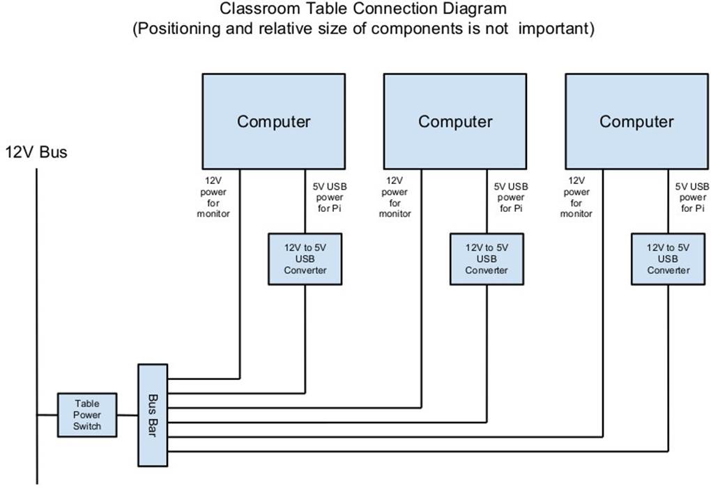
Figure 6-17. Classroom diagram
RACHEL completes the stetup. English and Spanish versions are available for download at http://worldpossible.org/rachel/download. They also offer installation instructions, or you can order preinstalled units.
—Emmanuel Ackerman
Hack 64. Build a MIDI Controller (on the Cheap!)
This hack helps you build a homemade MIDI controller, using the Raspberry Pi as a central controlling component, for a fraction of the cost of commercial devices.
The Alcyone, a Raspberry-Pi-based MIDI controller, was inspired by the Moog Taurus 2, including its astronomical name. However, if you’re familiar with these machines, the Roland PK-6 is more of a direct equivalent to the Alcyone. The goal was to create a MIDI controller in the form of bass pedals. Building a foot pedal would be far less expensive than purchasing a Moog Taurus 3 (a full analog synthesizer in a foot pedal form factor) or even a PK-6 (a simple foot pedal controller, at roughly $900 USD).
For those less familiar with music production, MIDI stands for musical instrument digital interface, and it’s an industry-standard protocol for electronic instruments. It is based on three types of events (note events, control events, and global events) and uses a serial connection at 31250 baud.
WHY “ALCYONE”?
The Moog Taurus was originally designed as a part of a synthesizer ensemble called the Constellation. The Taurus was the bass pedal of the ensemble; the other parts were the Lyra and the Apollo. The Lyra was never built; the Apollo’s design found its way into the PolyMoog. The Taurus, however, became very popular, through its use in bands such as Rush, Genesis, ELP (from whom the explanation of the Constellation comes), and others.
When naming this project, various star names were considered. Alcyone is Taurus’s second-brightest star and one of the Pleiades. The project Alcyone is pronounced “al-SEE-on-ee,” though the star is “al-SIGH-on-ee.” The warped pronunciation came from “halcyon,” which is a variant of the mythological character Alcyone’s name. “Halcyon” uses the “ee” form of the “y.”
The Alcyone is “merely” a MIDI controller; it does not generate any sound in and of itself. The actual processing power is provided through a Raspberry Pi, and the Raspberry Pi’s audio output is only 11 bits, which is better than, say, a Nintendo DS or some ancient digital synthesizers, but is far inferior to CD quality, and is nowhere near what you’d want for actual audio creation.
Hardware
The Alcyone uses a simple internal electronic design (shown in Figure 6-18). The pedals themselves are a 13-note chord, salvaged from an old Lowrey organ, purchased over eBay. They rely on a rocker switch that pulls a spring across a circuit to close it. You could build your own (or perhaps 3D-print your own) if organ salvage proves challenging.
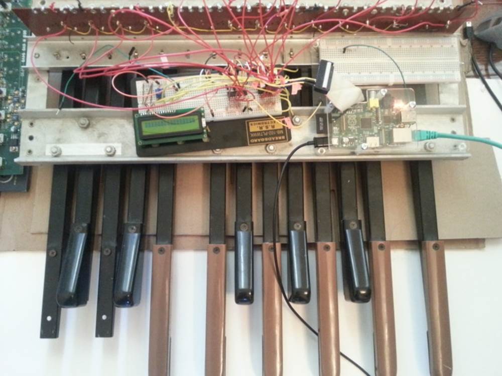
Figure 6-18. The Alcyone
In the Lowrey design, the pedals convert the circuit to a CV/Gate signal, which was a standard before MIDI was created. However, CV/Gate was never formally specified, so different manufacturers use different implementations. CV/Gate normally converts to a voltage: the first note might be +1 V, the second note +2 V, and so forth. However, this is a convention and not a standard, and the Raspberry Pi has neither analog inputs nor the capability to handle +13 V.
Thus it was simpler to use as little of the existing mechanism as possible, which meant relying solely on the rocker switch and wiring custom digital I/O. As the Pi has only a limited number of GPIO pins, the circuits for the rocker switches are wired to a set of I2C chips. These use a serial protocol to map GPIO pins. The MCP23008 offers eight individually addressible GPIO pins, and the MCP23017 offers 16.
The I2C chips can be wired such that seven of them are on a single serial connection. Thus, if you use seven MCP23008 chips in a series, you have 56 uniquely addressable pins. With the MCP23017, you could have 112. There are likely to be other I2C chips available, and you don’t have to have a homogenous chain.
The physical electronic circuit is thus simple: three MCP23008s in series with two of them dedicated to pedal input and one driving three LEDs for runtime status.
The pedals are connected to power (+5 V) and wired to the MCP23008s. The digital inputs are also connected to pull-down resistors to clear out digital noise.
The Raspberry Pi is connected to the I2C series and also to a Din5 connector (the industry standard for MIDI connections). The Din5 is mounted on a Sparkfun MIDI shield kit, mostly chosen for availability and ease of use.
A powered USB hub is also part of the hardware installation. The hub has one device attached, a wireless networking dongle. The powered hub is necessary because the Raspberry Pi does not carry enough current to reliably power most wireless dongles (see[Hack #8]).
WHY WIRELESS TCP/IP?
The wireless networking is part of a software choice made fairly early in the implementation cycle. Initial external control relied on the Raspberry Pi’s onboard Ethernet connection, which implies a requirement for networking infrastructure. However, one facet of the Alcyone’s potential use is stage work, and at many theaters, networking is spotty if existent at all.
The simplest solution involves the Alcyone serving as its own wireless access point, meaning that it provides its own networking infrastructure.
An alternative would be to avoid TCP/IP altogether. Bluetooth is another messaging protocol, one designed for device-to-device communications, particularly for short messages. Bluetooth devices can also be designed for low-power usage. However, this means writing a custom Bluetooth client for every possible client platform.
The wireless on the Raspberry Pi is configured as an access point so the Alcyone can serve as its own networking infrastructure. It has its own network SSID and security. The external client has to use this access point in order to control the Alcyone.
Not only does this avoid reliance on what might be inconsistent or nonexistent network services, it also limits the amount of traffic that competes for the client, and it also allows us to use a consistent IP for the Alcyone (as opposed to guessing what valid address the Alcyone happens to receive from the network infrastructure).
You need two packages to set this up: hostapd and udhcpd as described in eLinux.org‘s RPI Wireless Hotspot page.
Software
The software for the Alcyone comes in two artifacts: the actual embedded code (the code running on the Raspberry Pi) and an external client app (currently targeted for Android).
The embedded platform runs a single application (called alcyone of all things), written in C. C was chosen because the original test program was written on an Arduino Uno, which tends to encourage the use of Arduino “sketches,” which are themselves a form of C++ code (mostly with really odd library support).
C++ editing was largely done through Code::Blocks, easily installed for Fedora through:
$ su -c 'yum install codeblocks'
Interaction with the physical hardware is provided by Gordon Prescott‘s wiringPi library, an excellent utility with various language implementations.
It uses three threads, provided via boost::thread, to execute. All three threads are infinite loops. The Alcyone is a set of state machines, with the different machines able to affect the others.
The simplest thread is a “flare” machine. It loops through the output LEDs. The loop provides a timer value via an extern variable.
The second thread polls the digital inputs for changes in pedal state—in other words, when the pedals are pressed down and lifted up. The routine keeps track of two states: the “current state” based on a digital read, and the “previously read” state.
The current state is buffered to handle bounce.
Bounce is the natural tendency of an electrical current to fluctuate during changes. When a circuit is closed (or opened), electrons flow across it occasionally until the circuit settles in; the circuit appears to “bounce” open and closed for a short period of time. This makes consistent reads very difficult, unless you “debounce” the circuit.
There are two ways to debounce circuits. One hardware approach uses something called a Schmitt trigger buffer. Jack Ganssle has an excellent guide to debouncing that describes a few different ways to handle bounce in hardware and software (including code).
Alcyone uses a similar approach with a class that examines the input and counts the “open” and “closed” states. It’s possible that the debouncing mechanism could be fooled if the user plays quickly enough (pressing and releasing pedals much faster than the human eye can blink), but the sample frequency is high enough that we haven’t seen any incorrect results yet.
Through the process, on every loop, it reads the digital state of the pedals, and feeds that into the debouncing mechanism, yielding a result (biased toward the actual state).
If the current state is different from the “previously read” state, then we have a change; if the “current state” is “down,” then the pedal was just pressed, and we need to send a “note on” event; otherwise, a “note off” event should be sent.
Which note is sent is based on an offset. The MIDI mechanism contains a reference to a “current octave” and a “current transposition” setting; the actual note used is determined by multiplying the octave by 12, then adding the transposition value.
Therefore, if the current octave is three, and the transposition setting is one (meaning that the farthest left pedal is now C# and not C, an offset of one half-step), and the third pedal is depressed, the actual note is calculated through the use of the pedal, plus the octave offset, plus the transposition. The pedals start at zero, so the pedal number is two:
2 + 3*12 + 1 = 39
This actually yielded a bug in the initial demonstration of the Alcyone. If the transposition settings were changed while a note was being played, the “note off” event would be for the wrong note! The reason should be fairly apparent.
Assume the “note on” event is for note 39 (as in the calculation above). Now let us set the transposition to zero (i.e., reset it). Now, when the pedal is released, the “note off” value is calculated… at 38, instead of 39.
The “note off” event thus doesn’t correspond to the “note on” event, and therefore a receiver doesn’t actually get the correct signal to release the note.
This is corrected by the use of another data element, the “last note sent by this pedal.” Thus, note off events take the note value from this dataset, rather than recalculating the note value when the pedal is released.
Thus, the pedal press/release cycle follows this process:
1. Physically depress pedal (poor, sad pedal).
2. Calculate MIDI note by offset of pedal + 12*octave + transposition.
3. Store MIDI note in an internal array, index based on the offset of the pedal.
4. Send MIDI on.
5. Physically release the pedal.
6. Send MIDI off based on the note in the internal array.
MIDI actually required a number of changes to the Linux configuration for the Raspberry Pi.
The Pi’s serial driver does not actually support 31250 baud, the baud rate required by the MIDI specification. Therefore, you must overclock the serial chip, by modifying /boot/config.txt:
init_uart_clock=2441406
init_uart_baud=38400
Next, you must disable the serial console, which uses the RX/TX pins needed for MIDI, through modification of /boot/cmdline.txt:
dwc_otg.lpm_enable=0 console=tty1 console=tty1 root=/dev/mmcblk0p2 /
rootfstype=ext4 elevator=deadline rootwait bcm2708.uart_clock=3000000
Lastly, you must disable the TTY that would normally get assigned to the RX/TX pins, as well, by modifying /etc/inittab:
#Spawn a getty on Raspberry Pi serial line
#T0:23:respawn:/sbin/getty -L ttyAMA0 115200 vt100
The last thread is a simple web server, based on CoralBits’ libonion, which uses the C++ interface layer to map three request patterns (two with no-op responses for client performance). The Alcyone uses a simple web app written with JQuery (and served vialightttpd) to call this service with a single parameter: message. This app has a series of buttons corresponding to control events: two kinds of channel changes, four kinds of transposition events, and three different kind of system resets.
The message is actually an encoded byte, based on Table 6-5.
Table 6-5. Messages and encoded bytes
|
MESSAGE |
PAYLOAD |
NOTES |
|
MSG_MIDI_RESET |
0001 |
Turns off all MIDI notes on every channel |
|
xxxx |
||
|
MSG_MIDI_CHANNEL_CHANGE |
0010 |
|
|
vvvv |
||
|
MSG_MIDI_OCTAVE_CHANGE |
0100 |
|
|
vvvv |
MSG_MIDI_TRANSPOSITION_CHANGE |
|
|
1000 |
||
|
vvvv |
MSG_RESET |
1111 |
|
Resets the Alcyone’s internal state to defaults |
xxxx |
|
|
MSG_REQUEST_STATUS |
0011 |
Responds with three bytes: octave, transposition, channel |
In Table 6-5, xxxx is an “ignored value” and vvvv is “down if zero.”
The web service mechanism is a simple loop. It processes a request, has an internal switch/case that examines the upper nybble of the message value, and applies changes as required.
No matter what the requested operation is, the Alcyone responds with three integers in plain text, which correspond to the current octave, the current transposition setting, and the current MIDI channel. The JQuery-based request reads these three integers and populates the web page with the current instrument status.
Ergonomics
An implemented schematic and working software (both embedded and external) are all well and good, but they all ignore the actual aspect of playing the Alcyone.
The Alcyone is designed to be played by standing guitarists. It is not likely to be played delicately.
In order to be useful, it must be mounted in a case that offers the following qualities:
§ Heavy enough to allow stability for the pedals. It would be unfortunate for the musician if the pedals moved during performance (as many stage configurations are laid out for the convenience of the performer, and often monitors are aimed in specific ways). It would be even less fortunate for an audience member if the Alcyone were to somehow be launched at him or her.
§ Tough enough to handle being stepped on thousands of times, by a full-grown adult.
§ Pedals low enough so that the musician’s ankle is comfortable while playing the instrument.
All of the “white keys” were replaced with wooden keys made from wood meant for a picket fence cut down to size to match the existing pedals (roughly six inches long). These are more likely to be immediately durable as compared to the original organ pedals (which would be decades old).
As for the external container, the Alcyone has a wooden case built from 2 × 4 wood and shellacked fencing, giving it a rustic look (which has its own appeal, for various reasons) and is tough enough to handle rough treatment. With proper reinforcement, the Alcyone is strong enough for an adult to stand on, although you probably shouldn’t jump on it. It’s not a percussion instrument!
—Joe Ottinger
Hack 65. Build a Raspberry Pi Supercomputer
There seem to be two things people immediately want to do with their Pis: make a media server (see [Hack #54]) or make a cluster of Raspberry Pis. This hack is for those of you in the latter group.
Be þéos sceaft, sum clyster, nemnende for se eponymous ceorl fram… Just kidding. We’re talking a Beowulf cluster, not the Old English stuff. And not Old English like the wood cleaner, like the epic poem. Either way, it doesn’t matter. By the time we translated this whole hack into mediocre Old English, our grandchildren would be writing about installing Fedora 140 on the Lingonberry Muffin (all the rage in 2073—keep an eye out).
A Beowulf cluster is what happens when you connect some smaller computers (most likely some cheap bits somebody stuck in a storage closet a while back, or as Wikipedia more politely describes it, “commodity-grade”) together to build a supercomputer. The term came from such a computer built at NASA in the mid ’90s, so named because the eponymous character of Beowulf had “thirty men’s heft of grasp in the gripe of his hand.”
The following instructions are adapted from those written by Simon Cox in the Computational Engineering and Design Research Group at the University of Southampton for a Raspberry Pi supercomputer with LEGO racking. It uses MPI (Message Passing Interface) to communicate between nodes.
These instructions assume you are using Raspbian. When you first boot the image, expand the image to fill the card. Don’t forget to change the default password and refresh the list of packages in your cache (sudo apt-get update). Then you’re ready to start supercomputing!
BACKGROUND READING
Parallel Processing on the Pi is an excellent post to read, if only for reassurance that you are going to make it by the end, but don’t start following those instructions. You’re going to build everything yourself in this hack.
You’ll also want to look at the MPICH Installer’s Guide to better understand some of the steps in this hack.
Build MPI to Run Code on Multiple Nodes
To begin, get Fortran:
$ sudo apt-get install gfortran
After all, what is scientific programming without Fortran being a possibility?
If you have Fortran, you are good to go without excluding anything. The packages here are for armel, but you need armhf, so in this hack you’ll build MPI yourself.
Make a directory to put the MPI sources in:
$ mkdir /home/pi/mpich2
$ cd ~/mpich2
Next, get the MPI sources from Argonne National Laboratory. The MPI source continues to be updated, so you might need to visit http://www.mpich.org/downloads/ to find the latest stable release version for MPICH2:
$ wget http://www.mcs.anl.gov/research/projects/mpich2/downloads/tarballs/1.4.1p1/mpich2-1.4.1p1.tar.gz
Once you have it, unpack the file:
$ tar xfz mpich2-1.4.1p1.tar.gz
You will need to update this as the version of MPICH2 increments. Next, make a place to put the compiled stuff, which will also make it easier to figure out what you have put in new on your system:
$ sudo mkdir /home/rpimpi/
$ sudo mkdir /home/rpimpi/mpich2-install
You might end up building this a few times. Make a build directory (so you keep the source directory clean of build things) and then change into it:
$ sudo mkdir /home/pi/mpich_build
$ cd /home/pi/mpich_build
Now you’re ready to configure the build:
$ sudo /home/pi/mpich2/mpich2-1.4.1p1/configure -prefix=/home/rpimpi/mpich2-install
Again, you will need to update this as the version of MPICH2 increments. Now is a good time to go make a cup of tea. (We recommend Earl Grey, hot, but that part is up to you.) It will be waiting when you come back.
Make the files, have another cup of tea, install them, and have a third cup of tea:
$ sudo make
$ sudo make install
Add the place that you put the install to your PATH:
$ export PATH=$PATH:/home/rpimpi/mpich2-install/bin
Note that to put this on the path permanently you will need to edit .profile and add at the bottom these two lines:
# Add MPI to path
PATH="$PATH:/home/rpimpi/mpich2-install/bin"
Check whether things installed successfully:
$ which mpicc
$ which mpiexec
Now you’re ready to test whether MPI works for you on a single node. Change directory back to home (cd ~), make a directory for testing (mkdir mpi_testing), and change into your testing directory (cd mpi_testing). Get your IP address (ifconfig if necessary) and put it into a single file called machinefile.
Then, test whether MPI works:
$ mpiexec -f machinefile -n <number> hostname
If you run:
$ mpiexec -f machinefile –n 1 hostname
The output should look like this:
raspberrypi
Now try a little C code. In the examples subdirectory of where you built MPI, you’ll find the famous CPI example, which you will now use MPI on your Pi to calculate pi:
$ cd /home/pi/mpi_testing
$ mpiexec -f machinefile -n 2 ~/mpich_build/examples/cpi
Process 0 of 2 is on raspberrypi
Process 1 of 2 is on raspberrypi
pi is approximately 3.1415926544231318, Error is 0.0000000008333387
Take a break and celebrate getting this far! (Perhaps a fourth cup of tea is in order?)
Flash Me… Once
You now have a master copy of the main node of the machine with all of the installed files for MPI in a single place. It’s time to clone the card. Shut down your Pi (sudo poweroff). Remove the SD card and write the image from your SD card back to your PC. In the following example, we’ll call that file wheezy-raspbian_backup_mpi_master.img.
Eject the card and put a fresh card into your SD card reader. Write the wheezy-raspbian_backup_mpi_master.img image you just created to the SD card. Put this second card into your second Raspberry Pi and boot it. You should now have two Raspberry Pis on. Unless otherwise stated, all the commands that follow are typed from the Master Pi that you built first.
Use SSH Instead of Password Login Between the Pis
Using RSA will give you a much quicker login. Working on the master Pi node:
$ cd ~
$ ssh-keygen -t rsa –C “raspberrypi@raspberrypi”
This sets a default location of /home/pi/.ssh/id_rsa to store the key. Enter a passphrase (e.g., myfirstpicluster). If you leave this blank, you’ll have bad security, but you won’t have to type passphrases any more.
Next, copy the keys to the Raspberry Pi:
$ cat ~/.ssh/id_rsa.pub | ssh pi@192.168.1.162 "mkdir .ssh;cat >> .ssh/authorized_keys"
Log on to your second Pi and enter:
$ ls –al ~/.ssh
You should see a file called authorized_keys. This file is your ticket to No-Login Heaven on the nodes. Now add the new Pi to machinefile. Log into it and get its IP address (ifconfig). Working on the Master Raspberry Pi (the first one you built), machinefileshould now have both of the IP addresses for your Raspberry Pis—for example:
192.168.1.161
192.168.1.162
Again it’s time to run a little C code. Like before, you’ll find the CPI example in the examples subdirectory of where you built MPI. The first time, you will need to enter the passphrase for the key you generated (unless you left it blank) and the password for the second Pi:
$ cd /home/pi/mpi_testing
$ mpiexec -f machinefile -n 2 ~/mpich_build/examples/cpi
Process 0 of 2 is on raspberrypi
Process 1 of 2 is on raspberrypi
pi is approximately 3.1415926544231318, Error is 0.0000000008333387
If you repeat this a second time, you won’t need to type any passwords. Note that you have not changed the hostnames yet (so yes, the previous code is running on the two machines, but they both have the same hostname at the moment).
If you want to rename each machine, you can do it from the Master node:
$ ssh pi@192.168.1.162 'sudo echo "iridispi002" | sudo tee /etc/hostname'
$ ssh pi@192.168.1.163 'sudo echo "iridispi003" | sudo tee /etc/hostname'
$ ssh pi@192.168.1.164 'sudo echo "iridispi004" | sudo tee /etc/hostname'
You should then reboot each worker node.
If you put in the following command again:
$ mpiexec -f machinefile -n 2 ~/mpich_build/examples/cpi
Process 0 of 2 is on raspberrypi
Process 1 of 2 is on iridispi002
pi is approximately 3.1415926544231318, Error is 0.0000000008333387
This shows the master node still called raspberrypi and the first worker called iridispi002, and you see each process running on the separate nodes.
Congratulations! You’ve built a two-node supercomputer! Continue to build up to 64 (or more!) nodes.
Build More Nodes
You now have a copy of the worker nodes of the machine with all of the installed files for MPI in a single place. You want to clone this card, because it has the SSH key on it in the right place. Shut down your Pi (sudo poweroff) and eject the card. Put it into your SD card reader and write the image from your SD Card back to your PC, naming it wheezy-raspbian_backup_mpi_worker.img.
Eject the card and put a fresh card into the machine. Write the wheezy-raspbian_backup_mpi_master.img image you created from the PC to your card. Repeat for each additional node you would like to add.
Use Python Bindings for MPI
Now that your supercomputer is set up, you have options for various Python bindings for MPI. These instructions will get one of them, mpi4py working (read more about it at http://mpi4py.scipy.org).
Start by installing the package:
$ sudo apt-get install python-mpi4py
You also want to run the demo, so get the source, too:
$ cd ~
$ mkdir mpi4py
$ cd mpi4py
$ wget http://mpi4py.googlecode.com/files/mpi4py-1.3.tar.gz
$ tar xfz mpi4py-1.3.tar.gz
$ cd mpi4py-1.3/demo
Now repeat these steps on each of your other nodes, as this hasn’t been baked into the system image.
Run examples (on your master node):
$ mpirun.openmpi -np 2 -machinefile /home/pi/mpi_testing/machinefile python helloworld.py
Hello, World! I am process 0 of 2 on raspberrypi.
Hello, World! I am process 1 of 2 on iridispi002.
Then:
$ mpiexec.openmpi -n 4 -machinefile /home/pi/mpi_testing/machinefile python helloworld.py
Hello, World! I am process 2 of 4 on raspberrypi.
Hello, World! I am process 3 of 4 on iridispi002.
Hello, World! I am process 1 of 4 on iridispi002.
Hello, World! I am process 0 of 4 on raspberrypi.
GETTING PIP FOR RASPBERRY PI
Pip is a tool for installing and managing those Python packages, which will give you an easy way to do so with your cluster. Read more about it at http://www.pip-installer.org/en/latest/index.html.
Make a directory under your home called pip_testing and change into it. A prerequisite for pip is distribute, so let’s get that first and then install pip:
$ curl http://python-distribute.org/distribute_setup.py | sudo python
$ curl https://raw.github.com/pypa/pip/master/contrib/get-pip.py | sudo python
Notes on Making MPI Shared Libraries for Raspberry Pi
MPI libraries can also be built “shared” so that they can be dynamically loaded. This gives a library file that ends in .so. not .a, and you can do that by building those MPI libraries again.
To do so, repeat the steps beginning with making a directory for your MPI sources, but with a suffix of _shared on the directory names:
§ /home/pi/mpich2_shared
§ /home/rpimpi_shared/
§ /home/rpimpi_shared/mpich2-install_shared
§ /home/pi/mpich_build_shared
Configure the build:
$ sudo /home/pi/mpich2_shared/mpich2-1.4.1p1/configure -prefix=/home/rpimpi_shared/mpich2-install_shared --enable-shared
Follow the steps to make and install the files. Then add the place that you put the install to your PATH:
$ export PATH=$PATH:/home/rpimpi_shared/mpich2-install_shared/bin
Remember that to permanently put this on the path you will need to edit .profile and add at the bottom these two lines:
# Add MPI Shared to path
PATH="$PATH:/home/rpimpi_shared/mpich2-install_shared/bin"
ACTUALLY READ BEOWULF WHILE YOU WAIT FOR MAKE
If you don’t like tea, you can spend those tea-drinking steps reading John Lesslie Hall’s translation of Beowulf with notes and additional information at http://www.gutenberg.org/ebooks/16328 or the 1337 version (straight-up translation-only) by Francis Barton Gummere at http://www.gutenberg.org/ebooks/981
All materials on the site are licensed Creative Commons Attribution-Sharealike 3.0 Unported CC BY-SA 3.0 & GNU Free Documentation License (GFDL)
If you are the copyright holder of any material contained on our site and intend to remove it, please contact our site administrator for approval.
© 2016-2026 All site design rights belong to S.Y.A.