Raspberry Pi: A Quick-Start Guide, 2nd Edition (2014)
Chapter 9. Tinker with the GPIO Pins
The Raspberry Foundation built the Pi not only to teach kids how to program, but also to teach them how to tinker with electronics. That’s why the Pi has an expansion header that makes it easy to connect it to your own electronics projects.
In this chapter, you’ll learn how to build your own small electronics devices and control them with the Pi. We’ll start slowly and build a very basic circuit that makes a light-emitting diode (LED) shine. After that, we’ll control the LED using the Pi’s expansion header, and we’ll turn the LED on and off by issuing commands from the Pi.
Then we’ll build a small memory alarm that shows how much memory is left on the Pi. It will work like a traffic light, where a red light indicates that the amount of remaining memory is critically low. In addition, we’ll make the results of the memory alarm available in a web browser.
What You Need
To build all projects in this chapter, you need only a few cheap parts. (You can see them all in Figure 45, The parts you need.)
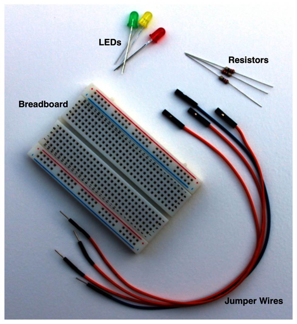
Figure 45. The parts you need
· A half-size breadboard
· Three 5mm LEDs (red, yellow, and green)
· Three resistors in the range of 220Ω to 1kΩ
· Four female/male jumper wires
You can get these parts at any shop that sells electronic parts—for example, RadioShack,[105] SparkFun,[106] Mouser,[107] Digi-Key,[108] and Adafruit.[109] Note that buying single LEDs, resistors, or jumper wires doesn’t make much sense. You can get these parts for much cheaper when you buy them as a pack. For example, RadioShack sells packs of LEDs (catalog number 276-1622) and resistors (catalog number 271-308). Adafruit has a nice pack of jumper wires (product ID 826), and it also sells breadboards (product ID 64).
Meet the Pi’s GPIO Pins
To connect your own electronics projects to the Pi, you can use the expansion header in the top-left corner of the Pi (see Figure 1, The front side of a Model B (Revision 1)). It consists of twenty-six pins arranged in two rows containing thirteen pins each. The top row contains the even-numbered pins, and the other row contains the odd-numbered pins. That is, the first pin in the lower row is pin 1, and you can find the label “P1” on the Pi below the pin.
In the following figure, you can see the meaning and the numbering of the pins. Note that the meaning of some pins has changed between revision 1 and revision 2. With the pins labeled Ground, the Pi can share a common ground with our electronics projects. Using the pins labeled 3v3 and 5V, you can power external devices connected to the Pi with 3.3 volts or 5 volts. The Pi limits the output of pin 1 to 50mA, while pin 2 allows for a current draw that depends on the USB input current. If you power the Pi with a 1A power supply, for example, you can draw up to 300mA from pin 2, because the Pi Model B needs 700mA for itself.
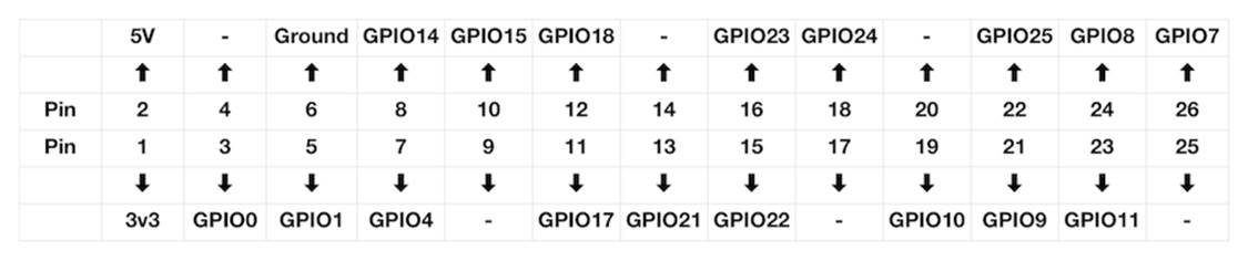
Figure 46. The Pi’s GPIO pins
In revision 1, pins 4, 9, 14, 17, 20, and 25 were reserved for future enhancements, so you couldn’t use them in your own projects. The remaining pins are general-purpose input/output (GPIO) pins that you can use as digital input or output pins. Note that the GPIO pin names don’t correspond to the pin numbers of the expansion header.
You can use the GPIO pins, for example, to read the state of a push button or to turn an LED on and off. For this chapter’s examples, you can assume that all GPIO pins work the same, but you should know that some of the Pi’s pins are special. Pin 12, for example, supports pulse-width modulation (PWM),[110] which can be handy for controlling motors. If you’re going to build more complex projects, you should take a look at a more detailed description of the Pi’s pins.[111]
Build a Basic Circuit
To warm up, we’ll build one of the most basic circuits possible. We’ll connect an LED to the Pi and make it shine as long as the Pi is running. For this we’ll need an LED, a resistor, a breadboard, and two female/male jumper wires. Using these parts, we’ll build the circuit shown in the following figure.
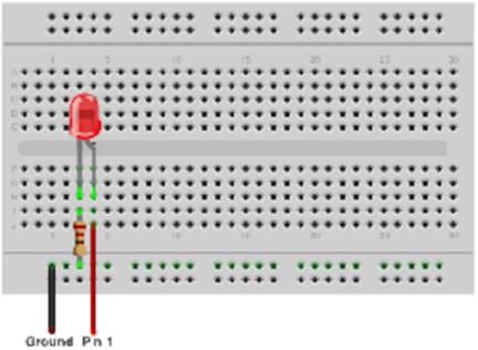
Figure 47. A basic circuit
Before we actually build the circuit, you should know what all the parts are for and how they work. Breadboards are useful tools for prototyping circuits. You can simply plug in parts such as LEDs and resistors, and you don’t have to solder them. Breadboards come in various sizes, but they all look very similar. On all of them, you can find many sockets arranged in columns. Most breadboards also have two rows of sockets at the top and at the bottom.
The main trick of a breadboard is that it automatically connects the sockets belonging to a certain column and to a certain row. In the basic circuit shown in the preceding figure, you connect the Pi’s ground pin to the second-to-last row of the breadboard. This automatically connects all sockets in this row to the Pi’s ground (which is why all the sockets in this row are light green). The same happens in the two columns connected to the LED. The resistor indirectly connects the Pi’s ground pin to one of the LED’s connectors. In addition, you connect the Pi’s pin 1 directly to the other connector of the LED by plugging it into a socket in the same column.
By the way, LED stands for light-emitting diode, so an LED is basically a diode. Diodes are useful because they let electricity pass in only one direction. That’s true for LEDs, too, and LEDs emit light as a side effect.
Working with LEDs isn’t very difficult, but we have to take care of a few things. First, we have to connect them the right way. LEDs have two wires, and one of them is a bit shorter than the other. The shorter wire is called a cathode (negative), and we have to connect it to the Pi’s ground pin. The longer wire is called an anode (positive), and we have to connect it to one of the Pi’s power supply or GPIO pins. You can also identify the anode and cathode by taking a close look at the LED’s case. The flat side belongs to the cathode and the round side to the anode. In Figure 47, A basic circuit, the anode is slightly bent.
Also, you always have to put a resistor in front of an LED. If you don’t, the LED will consume too much power and will be destroyed. Simply put, a resistor limits the amount of current that flows through an electric connection and protects the LED. Calculating the resistor value for a certain type of LED isn’t difficult, but it’s beyond the scope of this book. Simply keep in mind that the lower the resistor value, the brighter the light will shine. When in doubt, use a 330Ω or 470Ω resistor.
Now it’s time to actually build the circuit. First, connect the LED to the breadboard. Make sure that the LED’s direction is correct, and plug it in. You have to press firmly but not too hard—otherwise, you’ll bend the connectors, and they won’t fit. It’s usually easier to plug in parts after you’ve shortened the connectors. When cutting the connectors, wear safety glasses to protect your eyes!
The resistor is next, and this time the direction doesn’t matter. Before plugging in the resistor, you have to bend its connectors. Also, it usually helps to shorten them.
Finally, connect the two jumper wires to the Pi and to the breadboard. Connect the female side to the Pi and the male side to the breadboard. Make sure you’re using the correct pins on the Pi, and then turn on the Pi. If you’ve connected everything correctly, the LED will turn on, too. Otherwise, take a look at What If It Doesn’t Work?.
Control an LED Using the GPIO Pins
Making an LED shine is a fun exercise, but it gets boring pretty quickly. In this section, you’ll learn how to control an LED using software—we’ll turn it on and off by issuing commands on the Pi.
Programming hardware directly is usually a difficult task. Using the WiringPi project,[112] it becomes a piece of cake. WiringPi is an open-source project that hides the ugly low-level functions behind a nice, clean interface. If you’ve worked with the popular Arduino project[113] before, WiringPi will look very familiar because it tries to bring most of the Arduino goodies to the Pi. WiringPi not only makes programming the Pi’s hardware easier, but it also comes with a small command-line utility named gpio that allows you to control the hardware without writing code.
You can install WiringPi on the Pi as follows:
|
|
pi@raspberry:~$ cd /tmp |
|
|
pi@raspberry:~$ sudo apt-get install git-core |
|
|
pi@raspberry:~$ sudo apt-get update |
|
|
pi@raspberry:~$ sudo apt-get upgrade |
|
|
pi@raspberry:~$ git clone git://git.drogon.net/wiringPi |
|
|
pi@raspberry:~$ cd wiringPi |
|
|
pi@raspberry:~$ ./build |
These commands install the WiringPi libraries and the gpio command. You can use WiringPi from many programming languages, such as C, C++, Python, Ruby, and so on. In this chapter, we’ll use it exclusively from the command line and in a short but effective shell script.
All we need for our first interactive electronics experiments is the gpio command. It supports many useful options and a lot of powerful commands. The most important ones are mode, read, and write. For example, the following command sets the GPIO18 pin into output mode:
|
|
pi@raspberry:~$ gpio -g mode 18 out |
All GPIO pins can be in one of the following modes in, out, pwm, up, down, or tri. We’re only interested in in and out at the moment. To read digital signals from a GPIO pin, set its mode to in. Set it to out if you’d like to emit digital signals. You have to set a pin’s mode only once, and the pin will remember its mode until you set it to a different one.
After you’ve set GPIO18’s mode to out, you can turn it on like this:
|
|
pi@raspberry:~$ gpio -g write 18 1 |
Turning it off works similarly:
|
|
pi@raspberry:~$ gpio -g write 18 0 |
Finally, you can read GPIO18’s current state using the read command:
|
|
pi@raspberry:~$ gpio -g read 18 |
|
|
0 |
This command returns 0 if there’s currently no signal and 1 otherwise.
With gpio, we can control the LED on our breadboard easily. You have to connect it to only one of the Pi’s GPIO pins instead of connecting it directly to a power-supply pin. For example, you can use GPIO18, which is pin 12 in Figure 46, The Pi's GPIO pins. Choosing and addressing the correct pins can be a bit confusing because of the different naming and numbering schemes. By default, WiringPi uses its own numbering scheme,[114] but for our first experiments we’ll use the official GPIO pin names. Fortunately, gpio accepts them when you pass it the -g option.
So, in the circuit, disconnect the jumper wire from pin 1 and connect it to pin 12 instead. Then run the following commands:
|
|
pi@raspberry:~$ gpio -g mode 18 out |
|
|
pi@raspberry:~$ gpio -g write 18 1 |
These commands will turn on the LED, and the following command will turn it off:
|
|
pi@raspberry:~$ gpio -g write 18 0 |
gpio supports many more commands and options, and it really pays to read its manual page. For example, with the readall command, you can look at the current state of all the Pi’s GPIO pins (see Figure 48, Results of the readall command).
|
|
pi@raspberry:~$ gpio readall |
|
|
+----------+------+--------+-------+ |
|
|
| wiringPi | GPIO | Name | Value | |
|
|
+----------+------+--------+-------+ |
|
|
| 0 | 17 | GPIO 0 | Low | |
|
|
| 1 | 18 | GPIO 1 | Low | |
|
|
| 2 | 27 | GPIO 2 | Low | |
|
|
| 3 | 22 | GPIO 3 | Low | |
|
|
| 4 | 23 | GPIO 4 | Low | |
|
|
| 5 | 24 | GPIO 5 | Low | |
|
|
| 6 | 25 | GPIO 6 | Low | |
|
|
| 7 | 4 | GPIO 7 | Low | |
|
|
| 8 | 2 | SDA | High | |
|
|
| 9 | 3 | SCL | High | |
|
|
| 10 | 8 | CE0 | Low | |
|
|
| 11 | 7 | CE1 | Low | |
|
|
| 12 | 10 | MOSI | Low | |
|
|
| 13 | 9 | MISO | Low | |
|
|
| 14 | 11 | SCLK | Low | |
|
|
| 15 | 14 | TxD | High | |
|
|
| 16 | 15 | RxD | High | |
|
|
+----------+------+--------+-------+ |
|
|
| 17 | 28 | GPIO 8 | Low | |
|
|
| 18 | 29 | GPIO 9 | Low | |
|
|
| 19 | 30 | GPIO10 | Low | |
|
|
| 20 | 31 | GPIO11 | Low | |
|
|
+----------+------+--------+-------+ |
Figure 48. Results of the readall command
With only a few parts and a single command-line tool, we’ve created our first circuit. Even better, we can control it with the Raspberry Pi! In the next section, we’ll create a more complex project using the techniques we’ve discussed so far.
Build an Out-of-Memory Alarm
Turning an LED on and off using software is an important exercise, but it’s certainly not a very useful project. Usually, you won’t control LEDs manually, but you’ll use them as status indicators. For example, many USB devices use LEDs to show whether they’re reading or writing data at the moment.
In this section, we’ll use three LEDs as status indicators for the Pi’s current memory usage. The LEDs will have the same colors as a traffic light. If the Pi’s memory is critically low, we’ll turn on the red light. If a lot of memory is available, we’ll turn on the green light. Otherwise, it will be yellow.
In Figure 49, Memory alarm circuit diagram, you can see the circuit of the memory alarm. In Figure 50, The memory alarm circuit, you can see it in real life. It’s very similar to the last circuit we built. We have to copy the original LED circuit only two times to control three LEDs.
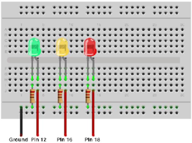
Figure 49. Memory alarm circuit diagram
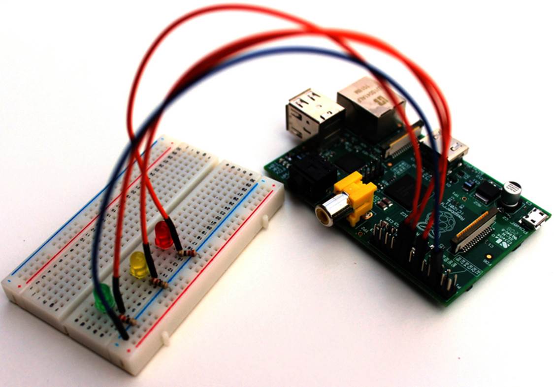
Figure 50. The memory alarm circuit
To make the circuit do something useful, we have to write some software. We could choose from a broad range of programming languages, but thanks to the gpio command, we can implement the project’s software with a simple shell script. The following statements define some constants and functions. Also, they perform some initializations.
|
gpio/memwatch.sh |
|
|
Line 1 |
#!/bin/bash |
|
- |
green=18 |
|
- |
yellow=23 |
|
- |
red=24 |
|
5 |
|
|
- |
init_leds() |
|
- |
{ |
|
- |
for i in $green $yellow $red |
|
- |
do |
|
10 |
gpio -g mode $i out |
|
- |
gpio -g write $i 0 |
|
- |
done |
|
- |
} |
|
- |
|
|
15 |
set_led() |
|
- |
{ |
|
- |
led_status=`gpio -g read $1` |
|
- |
if [ "$led_status" -ne 1 ] |
|
- |
then |
|
20 |
init_leds |
|
- |
gpio -g write $1 1 |
|
- |
fi |
|
- |
} |
|
- |
|
|
25 |
cleanup() |
|
- |
{ |
|
- |
init_leds |
|
- |
exit 0 |
|
- |
} |
|
30 |
|
|
- |
init_leds |
|
- |
trap cleanup INT TERM EXIT |
The first three lines define constants for the GPIO pins to which we’ve connected the LEDs. Note that the numbers in the constants refer to the pin names GPIO18, GPIO23, and GPIO24. They don’t refer to the expansion header’s pin numbers 12, 16, and 18.
The init_leds function in line 6 sets the mode of all three LEDs to output and turns them off. The set_led function turns on a certain LED and turns off the other ones. Before turning on the LED, it checks whether the LED is already on. This ensures that the LED doesn’t flicker in case the current status hasn’t changed. Finally, the cleanup function turns off all LEDs and exits the program.
To initialize the program, we have to call init_leds. To make sure that the program cleans up before it stops, we can use the trap command in line 32. This command binds the cleanup method to the most common exit signals, so if we terminate the script, it will call cleanup before it shuts down.
Now that we’ve initialized everything properly, we can write the alarm’s business logic. Therefore, we need to find a way to determine the Pi’s current memory status, and the free command is the perfect solution to this problem.
|
|
pi@raspberry:~$ free |
|
|
total used free shared buffers cached |
|
|
Mem: 190836 40232 150604 0 6252 21068 |
|
|
-/+ buffers/cache: 12912 177924 |
|
|
Swap: 0 0 0 |
To calculate the percentage of memory available, we have to cut out the amount of total memory and the amount of free memory from the free command’s output. After that, we have to turn on the correct LED depending on the percentage value. Here’s how to do this:
|
gpio/memwatch.sh |
|
|
Line 1 |
while : |
|
- |
do |
|
- |
total=`free | grep Mem | tr -s ' ' | cut -d ' ' -f 2` |
|
- |
free=`free | grep Mem | tr -s ' ' | cut -d ' ' -f 4` |
|
5 |
available=$(( free * 100 / total )) |
|
- |
echo -n "$available% of memory available -> " |
|
- |
|
|
- |
if [ "$available" -le 10 ] |
|
- |
then |
|
10 |
echo "Critical" |
|
- |
set_led $red |
|
- |
elif [ "$available" -le 30 ] |
|
- |
then |
|
- |
echo "Low" |
|
15 |
set_led $yellow |
|
- |
else |
|
- |
echo "OK" |
|
- |
set_led $green |
|
- |
fi |
|
20 |
sleep 10 |
|
- |
done |
The memory monitor should permanently check the current memory status so the whole logic runs in an endless loop. Lines 3 to 5 calculate the percentage of memory available by calling the free command two times and cutting out the relevant information. Note that this solution has a potential flaw. If the current memory usage changes significantly between the two calls to free, we’ll get bad results. This isn’t very likely, but it might happen, so for a production system we’d have to find a more sophisticated way to determine the current memory usage. For a prototype, it’s sufficient.
The following lines compare the memory available to a few threshold values. If the available memory is less than or equal to 10 percent of the total memory, the program turns on the red LED. If it’s between 10 and 30 percent, it turns on the yellow LED. Otherwise, the green LED will shine. Finally, the program goes to sleep for 10 seconds, so it doesn’t waste a lot of CPU time.
Now type in the shell script or download it by clicking the filename above the code, and copy it to the Pi. The following statement will make the script executable:
|
|
pi@raspberry:~$ chmod a+x memwatch.sh |
Then you can start it as follows:
|
|
pi@raspberry:~$ ./memwatch.sh |
|
|
78% of memory available -> OK |
To test the out-of-memory alarm, start the LXDE desktop environment and run the script in a terminal. Then open a few applications and see how the amount of available memory shrinks.
Display the GPIO Status in a Browser
In Chapter 6, Networking with the Pi, you learned how to set up a web server and PHP5 on the Pi. Now we can use this web server to display the Pi’s current memory usage in a web browser. Copy the following PHP program to your Pi’s /var/www directory:
|
gpio/memwatch.php |
|
|
|
<?php |
|
|
function led_is_on($number) { |
|
|
$status = trim(@shell_exec("/usr/local/bin/gpio -g read " . $number)); |
|
|
if ($status == "0") { |
|
|
return False; |
|
|
} else { |
|
|
return True; |
|
|
} |
|
|
} |
|
|
$green = 18; |
|
|
$yellow = 23; |
|
|
$red = 24; |
|
|
echo "<h1>Memory Usage is "; |
|
|
if (led_is_on($green)) { |
|
|
echo "OK"; |
|
|
} |
|
|
elseif (led_is_on($yellow)) { |
|
|
echo "Low"; |
|
|
} |
|
|
elseif (led_is_on($red)) { |
|
|
echo "Critical"; |
|
|
} |
|
|
else { |
|
|
echo "Unknown"; |
|
|
} |
|
|
echo ".</h1>"; |
|
|
?> |
Start the memwatch.sh script and then point your browser to the memwatch.php file. If the Pi’s IP address is 192.168.2.109, for example, we have to use the URL http://192.168.2.109/memwatch.php. The browser will display a short message explaining the current memory situation on the Pi.
Even if you’ve never used PHP before, you should be able to understand what the program does. In the led_is_on function, it calls the gpio command and reads the current status of a GPIO pin. If the pin is currently on, the function returns True; otherwise, it returns False. After that, the program checks which of the LEDs is on and emits a corresponding message.
As you’ve seen, it’s easy to make the status of an electronics device available in your network. Of course, you can make this page more colorful and turn it into a real traffic-light display, but that is beyond the scope of this book.
What If It Doesn’t Work?
Building your own electronics devices isn’t rocket science, but it’s not extremely simple, either. If you’ve never worked with a breadboard, LEDs, and resistors before, many things can and will go wrong. Even if you have a lot of experience, you’ll still make mistakes.
If something doesn’t work as expected, don’t panic! Usually, the cause of the problem is very simple. The first thing you should check is whether you’ve connected all parts to the correct pins. Then you should check the direction of the LEDs. Also, make sure that all parts fit correctly into place. Plugging parts into breadboards can be tricky, especially when the breadboard is new.
Don’t forget to plug in the power supply, and don’t proceed with your project until you have the simplest version working.
Next Steps
In this chapter, you learned how to build your own electronics projects and control them with the Raspberry Pi. Even though you used only a few cheap parts, you could actually build something fun and useful.
The next chapter will show you how to do even more exciting stuff. You’ll connect digital and analog sensors to the Pi, so you can detect motion and measure the current temperature, for example.
Footnotes
|
[105] |
http://radioshack.com |
|
[106] |
http://www.sparkfun.com/ |
|
[107] |
http://mouser.com |
|
[108] |
http://digikey.com |
|
[109] |
http://adafruit.com |
|
[110] |
http://en.wikipedia.org/wiki/Pulse_width_modulation |
|
[111] |
http://elinux.org/RPi_Low-level_peripherals |
|
[112] |
http://wiringpi.com/ |
|
[113] |
http://arduino.cc |
|
[114] |
https://projects.drogon.net/raspberry-pi/wiringpi/pins/ |
All materials on the site are licensed Creative Commons Attribution-Sharealike 3.0 Unported CC BY-SA 3.0 & GNU Free Documentation License (GFDL)
If you are the copyright holder of any material contained on our site and intend to remove it, please contact our site administrator for approval.
© 2016-2026 All site design rights belong to S.Y.A.