Raspberry Pi: A Quick-Start Guide, 2nd Edition (2014)
Chapter 10. Working with Digital and Analog Sensors
Sensors are everywhere today, and many of them have become so ubiquitous that often you don’t even notice them. When entering a grocery store, you expect the doors to open automatically. Using temperature sensors, your car automatically turns on the heat to defrost the side mirrors. Distance sensors help you to navigate even the tiniest parking spots.
Of course, you can also find plenty of sensors in your tablet PC and in your smartphone. For example, acceleration sensors turn the screen to landscape or portrait mode automatically; you can also use them for controlling video games.
Attaching sensors to a PC usually isn’t so easy. Fortunately, the Pi is different—you can connect it to many intelligent sensors with little effort, although it’s still not as easy as using sensors with a microcontroller board, such as the Arduino. In this chapter, you’ll learn how to enhance your Pi with both digital and analog sensors.
What You Need
To build all the projects in this chapter, you need the parts you see in Figure 51, The parts you need.
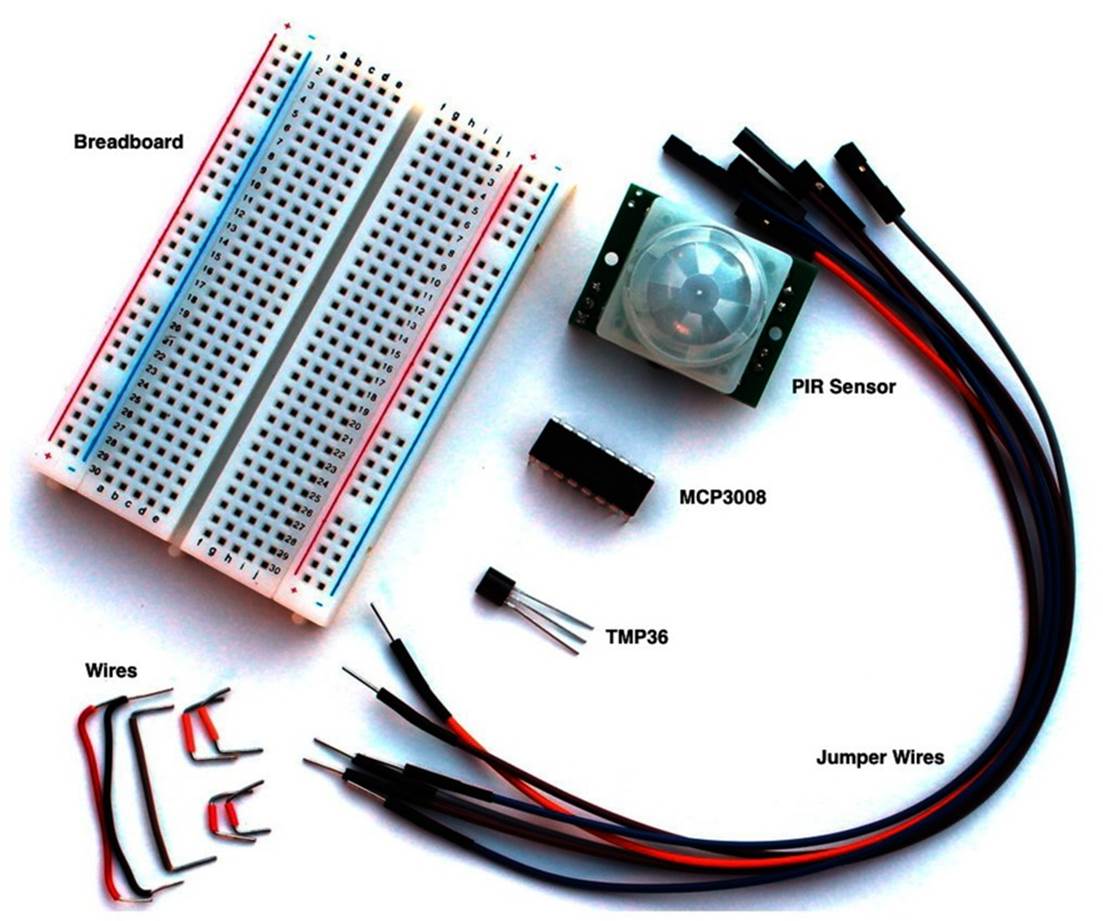
Figure 51. The parts you need
· A half-size breadboard
· A PIR sensor
· A TMP36 temperature sensor
· An MCP3008-I/P analog-to-digital converter
· Six female/male jumper wires
· Some wires
You already learned where you can get a breadboard and wires in What You Need. Most of the vendors mentioned there also sell the two sensors and the MCP3008 chip. For example, Adafruit sells a PIR sensor (product ID 189), the TMP36 (product ID 165), and the MCP3008 (product ID 856). If you prefer the Parallax PIR sensor, make sure you’re using Rev A.[115] The new version (Rev B) is a bit better, but its output voltage might be too high for the Pi. Also, Rev A costs less than five dollars at the moment and is sufficient for most purposes.
Make sure you buy the correct version of the MCP3008 chip, because they’re available with different cases. You need the MCP3008-I/P (16 pins), because you can use it with a breadboard.
WARNING! Never attach a sensor that outputs more than 3.3V directly to the Pi. It will damage your Pi! Be very careful when buying new parts for the Pi.
Detect Motion with the Pi
Chances are good that you benefit from motion detectors several times a week or even several times a day. They might turn on the lights automatically at dark, or perhaps they turn on the lights when you enter the restroom at work. In this section, you’ll learn how these detectors work, and you’ll learn how to turn the Pi into a motion detector.
Connect the PIR Sensor to the Pi
Many motion detectors use passive infrared (PIR) sensors.[116] A PIR sensor permanently measures infrared light and notices whenever something in the infrared spectrum changes. This is all you need to detect motion, because nearly every object emits infrared light. That’s true for everything in front of your house: the ground, a bicycle, a garbage can, and so on. All of these things emit a fairly constant portion of infrared light, and it doesn’t change rapidly. But if a human being or an animal approaches your front door, the sensor will notice a big variation and fire a signal.
The innards of PIR sensors are rather complex, but using them is easy. In the following figure, you can see the Parallax PIR sensor (Rev A) that we’ll use in this section’s examples. The sensor has a jumper you can use for changing its behavior. Make sure it’s in position H; that is, the jumper covers the pin next to the H.[117]
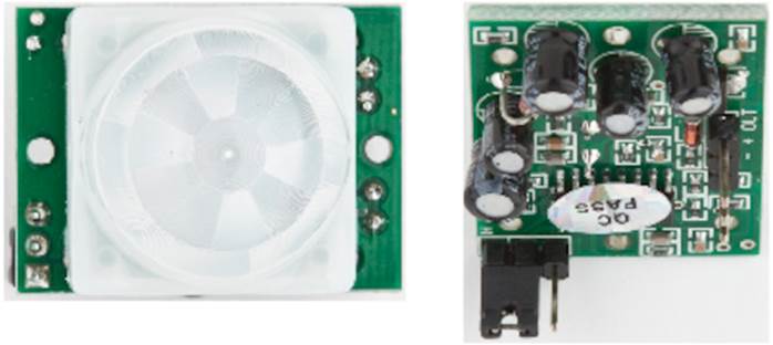
Figure 52. Top and bottom of a passive infrared sensor
Also, the sensor has three pins that you need to connect to the Pi using female/male jumper wires. In the following figure, you can see how. Connect the Pi’s 5V pin to the sensor’s power pin and the Pi’s ground pin to the sensor’s ground pin. Finally, connect the sensor’s signal pin to pin GPIO23 on the Pi. Usually, the pins on the sensor are labeled. When in doubt, look at the sensor’s data sheet.
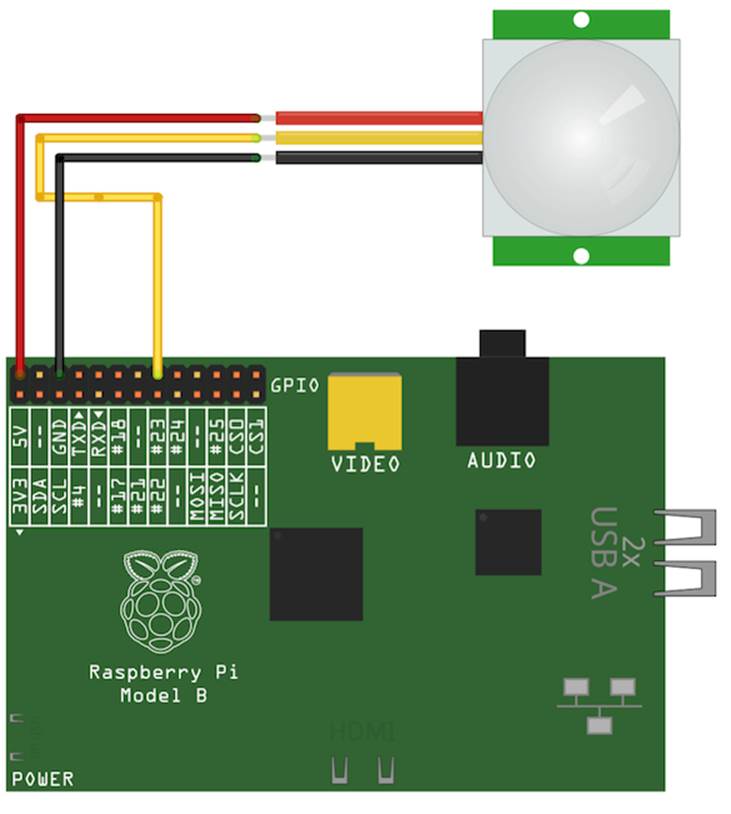
Figure 53. The PIR circuit
All digital PIR sensors work more or less the same way. As long as they don’t detect motion, they don’t output any current on their signal pin. When they detect motion, they output a high signal—that is, a certain current that you can usually look up in the sensor’s data sheet.
WARNING AGAIN! Never attach a sensor that outputs more than 3.3V directly to the Pi. It will damage your Pi!
Control a PIR Sensor
Now that the wiring is finished, we have to control the sensor using some software. For many programming tasks on the Pi, the Python programming language[118] is a good choice. It’s easy to learn, and the RPi library[119] has many convenient functions for controlling the Pi’s GPIO pins. Raspbian already comes with Python, but you have to install RPi:
|
|
pi@raspberry:~$ sudo apt-get update |
|
|
pi@raspberry:~$ sudo apt-get install python-dev python-rpi.gpio |
That’s all the preparation we need, and now we can define a new Python class for working with a PIR sensor:
|
Sensors/pir.py |
|
|
Line 1 |
import RPi.GPIO as GPIO |
|
2 |
class PassiveInfraredSensor: |
|
3 |
def __init__(self, pin): |
|
4 |
self.pin = pin |
|
5 |
GPIO.setmode(GPIO.BCM) |
|
6 |
GPIO.setup(self.pin, GPIO.IN) |
|
7 |
|
|
8 |
def motion_detected(self): |
|
9 |
return GPIO.input(self.pin) |
Even if you’ve never worked with Python before, you should be able to understand most of the code. Before we dissect the code line by line, you should know that Python treats whitespace differently from most other programming languages. Instead of creating code blocks using curly braces ({ }) or keywords such as begin and end, Python uses indentation. It doesn’t matter whether you use spaces or tabs to indent a block of code, but you have to be consistent. That is, if you’ve indented the first line of a block using four spaces, you have to indent the next line using four spaces, too.
In the first line we import RPi’s GPIO functions, so we can use them in our own code. Then we define a new class named PassiveInfraredSensor. Whenever we create a new PassiveInfraredSensor object, Python will call the _ _init_ _ function. This function expects two arguments: the newly created object (self) and the number of the pin to which we’ve connected the sensor (pin). Python will initialize the first argument automatically.
In line 4, we store the pin number in the current object, and after that we set the numbering scheme for the pins using the GPIO.setmode function. We pass it the value GPIO.BCM, so the RPi library interprets pin numbers using the Broadcom definition. (See the top and bottom rows in Figure 46, The Pi's GPIO pins.) In our case, the pin number is 23 because we have connected the sensor’s signal pin to pin GPIO23 on the Pi.
Alternatively, we can set the mode to GPIO.BOARD. In this case, RPi interprets pin numbers as they are defined on the Raspberry Pi board, and we’d have to use 16 instead with our current setup. (See the two rows in Figure 46, The Pi's GPIO pins, beginning with Pin.) Finally, we turn the pin to which the sensor is connected into an input pin by calling GPIO.setup in line 6.
Then we define a method named motion_detected. It calls GPIO.input, passing it our signal pin number. Depending on the method call’s result, it returns True if the sensor has detected a motion and False otherwise. Again, Python sets the self argument automatically for us.
Our PassiveInfraredSensor class is complete now, so let’s use it to build a motion detector. The following program periodically checks whether the PIR sensor has detected motion. It prints a message if someone moves, and it also prints a message if nobody has moved for more than two seconds.
|
Sensors/pir_demo.py |
|
|
Line 1 |
from pir import * |
|
- |
import time |
|
- |
|
|
- |
PIR_PIN = 23 |
|
5 |
pir = PassiveInfraredSensor(PIR_PIN) |
|
- |
|
|
- |
last_state = False |
|
- |
while True: |
|
- |
if (pir.motion_detected() == True): |
|
10 |
if (last_state == False): |
|
- |
print "Movement detected" |
|
- |
last_state = True |
|
- |
else: |
|
- |
if (last_state == True): |
|
15 |
print "No movement detected" |
|
- |
time.sleep(2) |
|
- |
last_state = False; |
In the first two lines, we import the PassiveInfraredSensor class and Python’s functions for manipulating dates and times. Then we define a constant named PIR_PIN and set it to the number of our signal pin. We use the constant in the following line when we create a newPassiveInfraredSensor object for the first time.
The detection algorithm starts in line 7. We store the last state of the PIR sensor in a variable named last_state. Then we start an endless loop and check to see whether the PIR sensor has currently detected a motion. If yes, we check whether this is a new motion or whether we have detected it before. If it is new, we print the message “Movement detected.”
If the PIR sensor hasn’t detected a motion, we check whether it has previously detected a motion. If it has, we print the message “No movement detected” and wait for two seconds until we start again. Overall, we make sure that we print a message only if the state has actually changed. This prevents our motion detector from looking a bit nervous.
Now run the program, move a little in front of the PIR sensor, and stand still from time to time.
|
|
pi@raspberry:~$ sudo python pir_demo.py |
|
|
Movement detected |
|
|
No movement detected |
That’s all you need to turn the Pi into a motion detector. Printing a message isn’t very spectacular, but you can easily improve the program so that it sends an email or switches on a light. That way, you could turn your Pi into a burglar alarm or make it the basis of a home-automation system.
Attaching most digital sensors to the Pi is easy as long as their output voltage matches the Pi’s specifications and as long as they don’t depend on an accurate timing. Working with analog sensors can be more complicated, but in the next section you’ll see that it isn’t rocket science, either.
Measure Temperature with the Pi
Digital sensors have many applications and are easy to use, but in many cases analog sensors have some advantages. For example, most processes in nature are analog, so analog sensors are a better fit for measuring phenomena such as temperature or acceleration.
Analog sensors usually measure a certain parameter and output a voltage that corresponds to the size of their current input signal. For example, a temperature sensor such as the TMP36 outputs a higher voltage for higher temperatures and a lower voltage for lower temperatures.
Although this sounds reasonable and easy, we still have a problem: digital computers like the Raspberry Pi don’t understand analog voltage signals. They can only interpret digital signals—that is, HIGH or LOW current. Microcontroller boards such as the Arduino have native support for analog signals because they have an analog-to-digital converter (A/D) that takes a voltage signal and turns it into a binary number. To achieve the same with the Raspberry Pi, we need to attach an A/D to the Pi.
Meet the MCP3008
The MCP3008[120] is an A/D that works great with the Pi. It’s cheap, it’s easy to use, and it can read up to eight analog signals at the same time. Its output resolution is 10 bits; that is, it returns numbers in the range of 0 to 1023 corresponding to the voltage signal emitted by an analog sensor. You can see the MCP3008’s pins in the following figure.
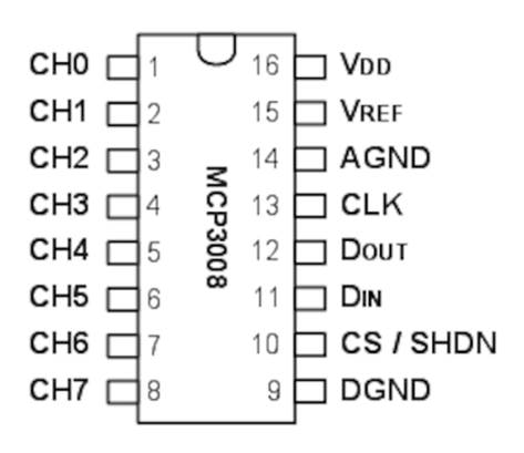
Figure 54. The pin layout of an MCP3008 A/D
You can use pins 1 to 8 on the left side to connect up to eight analog sensors. Half the pins on the right side are needed for the power supply and ground (VDD, VREF, AGND, and DGND). With the remaining four pins (CLK, DOUT, DIN, and CS), you can read the current voltage signal as a digital number.
The MCP3008 has a resolution of 10 bits, so you might be wondering how it’s possible to transfer 10 bits using only four digital pins. You might expect the chip to have ten pins for emitting the value of the current analog signal. In theory that’s a good idea, but adding ten pins would be wasteful. Not only would the MCP3008 need more pins, but the Pi would need more pins, too.
That’s why the MCP3008 does something more sophisticated to output its readings. It implements the Serial Peripheral Interface (SPI).[121] SPI allows you to create a synchronous serial link between a master and several slaves. The master and slaves communicate via a serial bus; in our case, the Pi is the master and the MCP3008 is the slave. Whenever the Pi wants to read an analog signal, it sends a message to the MCP3008 and gets back a response. To establish an SPI bus between two devices, you need four wires.
In the following figure, you can see how to connect the Pi to the MCP3008 so they can communicate using SPI. (Don’t worry! You’ll see the rest of the wiring next.)
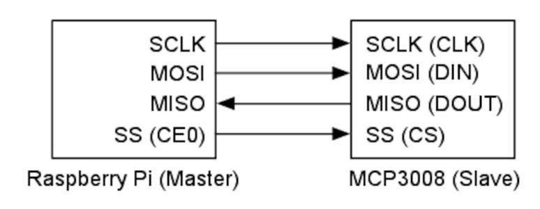
Figure 55. This is how you connect two SPI devices.
Note that SPI isn’t a very strict specification, so different vendors use different labels for their pins. With the SCLK line, the master and the slave synchronize their work using a common clock signal. The MOSI (Master Out, Slave In) line is for sending data from the master to the slave, while MISO (Master In, Slave Out) is for transferring data back from the slave to the master. Using the SS line (Slave Select), the master selects the slave it wants to do some work.
Implementing SPI communication in software isn’t difficult, but the Pi’s hardware supports it out of the box. The same is true for Raspbian. In the next section, you’ll learn how to enable it.
Enable SPI on the Pi
By default, Raspbian doesn’t enable SPI, so you need to either enable it using raspi-config (see Enable the SPI Kernel Module) or adjust a few configuration files. If you’re working with a recent version of Raspbian, you’ll find an option named SPI in raspi-config’s Advanced Options menu. Choose this option, enable SPI, and you’re finished.
If you’re working with an older release or prefer to enable SPI manually, you’ll need to remove SPI from the module blacklist by editing /etc/modprobe.d/raspi-blacklist.conf:
|
|
pi@raspberry:~$ sudo nano /etc/modprobe.d/raspi-blacklist.conf |
As of this writing, this file contains only two lines for disabling SPI and I2C. It probably looks like this:
|
|
blacklist spi-bcm2708 |
|
|
blacklist i2c-bcm2708 |
To remove SPI support from the blacklist, you need to comment out the corresponding line so the file looks like this:
|
|
#blacklist spi-bcm2708 |
|
|
blacklist i2c-bcm2708 |
Alternatively, you can delete the line. Save the file and then add the SPI module to the list of modules the Pi loads automatically when it starts:
|
|
pi@raspberry:~$ sudo nano /etc/modules |
Add a new line containing only the word spidev and save the file. Then reboot the Pi:
|
|
pi@raspberry:~$ sudo reboot |
Now your Pi should support two SPI devices. You can look them up using the following command:
|
|
pi@raspberry:~$ ls /dev/spidev* |
|
|
/dev/spidev0.0 /dev/spidev0.1 |
In the next section, we’ll bring one of these devices to life by connecting an MCP3008 and a temperature sensor to the Pi.
Wire It All Up
Now that we know how SPI works in principle, we need to connect the Pi to the MCP3008, and the MCP3008 to the TMP36 temperature sensor. In Figure 56, The TMP36 circuit, you can see how to do this.
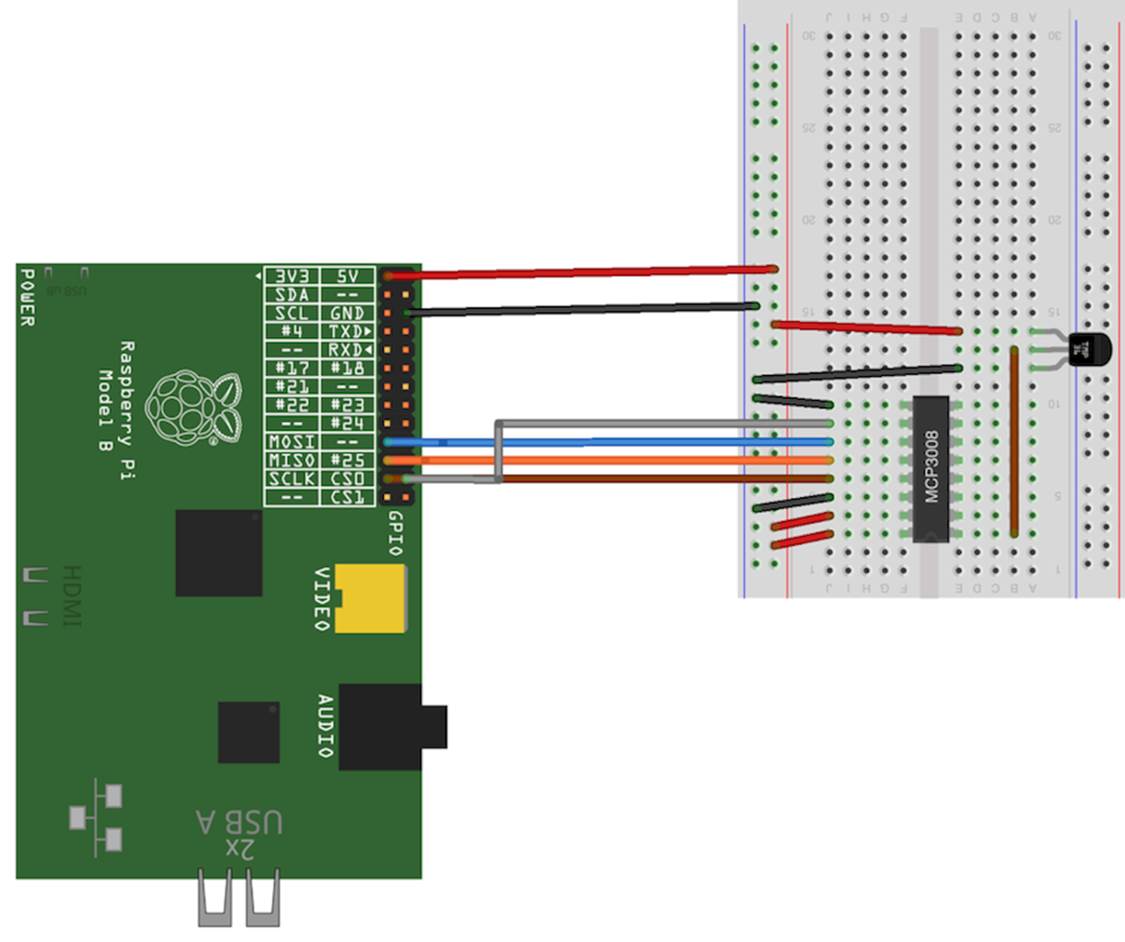
Figure 56. The TMP36 circuit
We need to connect the Pi’s power and ground pins to a couple of places on the breadboard. So, we connect them to the two rows at the left of the breadboard. From there, we can easily distribute power and ground to other places using short wires.
Next we plug in the MCP3008 chip; we have to make sure it has the right orientation. Chips have a U notch at the top, and the MCP3008 is no exception. Pin 1 is to the left of the U notch. Gently plug it into the breadboard. You’ll have to press firmly after you get them all lined up, but first double-check to ensure that all pins fit into their holes. Use a small screwdriver as a lever if you need to remove the chip.
Also, be very careful when wiring the MCP3008 to the Pi. Table 1, Pin mapping for connecting the Pi to the MCP3008 explains in detail how to connect the Pi’s GPIO pins to the MCP3008.
Table 1. Pin mapping for connecting the Pi to the MCP3008
|
Raspberry Pi Pin |
MCP3008 Pin |
|
1 (3.3V) |
16 (VDD) |
|
1 (3.3V) |
15 (VREF) |
|
6 (GND) |
14 (AGND) |
|
6 (GND) |
9 (DGND) |
|
23 (SCLK) |
13 (CLK) |
|
21 (MISO) |
12 (DOUT) |
|
19 (MOSI) |
11 (DIN) |
|
24 (CE0) |
10 (CS) |
Connecting the TMP36 sensor is easy because it has only three pins. Plug the sensor into the breadboard and make sure it has the correct orientation. Connect the sensor’s power pin to the Pi’s 3.3V pin and its ground pin to the Pi’s ground. Then connect the TMP36’s signal pin to pin 1 (CH0) of the MCP3008.
So, the wiring is finished. Now we need to write some software so that we can finally find out what the temperature is.
Control the MCP3008
The MCP3008 is an SPI device, so we need to find a way to communicate with it using the Pi’s SPI hardware. Fortunately, several people have already done this. py-spidev[122] is a small library that provides everything we need. Install it as follows:
|
|
pi@raspberry:~$ sudo apt-get install python-dev python-rpi.gpio |
|
|
pi@raspberry:~$ git clone git://github.com/doceme/py-spidev |
|
|
pi@raspberry:~$ cd py-spidev |
|
|
pi@raspberry:~$ sudo python setup.py install |
The following is all we need to implement an MCP3008 class using Python:
|
Sensors/mcp3008.py |
|
|
Line 1 |
import spidev |
|
- |
|
|
- |
class MCP3008: |
|
- |
def __init__(self, bus = 0, client = 0): |
|
5 |
self.spi = spidev.SpiDev() |
|
- |
self.spi.open(bus, client) |
|
- |
|
|
- |
def analog_read(self, channel): |
|
- |
if (channel < 0 or channel > 7): |
|
10 |
return -1 |
|
- |
result = self.spi.xfer2([1, (8 + channel) << 4, 0]) |
|
- |
return ((result[1] & 3) << 8) + result[2] |
It’s just a short class, but it needs some explanation. In the first line we import the spidev library we installed before. Then we define a class named MCP3008. As before, in the PassiveInfrared class, we define a method named _ _init_ _ that will be called whenever we create a new MCP3008object. _ _init_ _ expects three parameters: the newly created instance (self), the number of the SPI bus to be used (bus), and the number of the client (slave) we’d like to talk to (client). In line 5, we create a new SpiDev object, and we open a connection to the device in the following line.
So far we’ve only established a communication channel to an SPI device; that is, what we do in the _ _init_ _ method isn’t specific to the MCP3008. It would be the same for every other SPI device. The specific parts happen in analog_read. This method takes a port number and returns the current reading of the analog sensor that has been connected to the port. We check whether the port number is between 0 and 7, and if it’s not we return –1.
In line 11, we send a message to the MCP3008 using the xfer2 method of our SpiDev object. xfer2 expects an array of bytes and sends it using the SPI protocol. In our case we need to send 3 bytes, and you might be wondering what their meaning is. You can find the answer in Chapters 5 and 6 of the MCP3008’s data sheet.[123] The data sheet explains in detail what data the MCP3008 expects and what data it sends back. The structure of the input message looks like this:

Most of the bits in these 3 bytes have a constant value. Only the 3 bits named D0, D1, and D2 may vary, and they contain the number of the channel you’d like to read. So the first byte is always 1, the last byte is always 0, and the second byte contains a slightly shifted version of the channel number. We set all bits marked with an x to 0.
The MCP3008’s response message consists of 3 bytes, too. Their meaning is:

Only the lower 10 bits are interesting; ignore the rest. Line 12 extracts the interesting bits and returns them as a single number.
With the MCP3008 class, it’s easy to read the current temperature:
|
Sensors/tmp36_demo.py |
|
|
Line 1 |
from mcp3008 import * |
|
- |
import time |
|
- |
|
|
- |
mcp = MCP3008() |
|
5 |
TMP36_CHANNEL = 0 |
|
- |
|
|
- |
while True: |
|
- |
analog_value = mcp.analog_read(TMP36_CHANNEL) |
|
- |
voltage = 3.3 * analog_value / 1024 |
|
10 |
temperature_c = (voltage * 1000 - 500) / 10 |
|
- |
temperature_f = 9.0 / 5.0 * temperature_c + 32.0 |
|
- |
print "Temperature: %.1fC (%.1fF)" % (temperature_c, temperature_f) |
|
- |
time.sleep(1) |
After importing the MCP3008 class and Python’s time functions, we create a new MCP3008 object in line 4. We also define a constant for the channel to which we connected the TMP36 sensor.
We start an endless loop and read the TMP36’s current value by calling analog_read. In line 9, we turn this value into the actual voltage emitted by the sensor. The following line calculates the actual temperature in degrees Celsius using a formula you can find by studying the sensor’s data sheet.[124] We convert this value into degrees Fahrenheit, too, and print them both. Then we wait for a second and measure the current temperature again.
Run the program, and its output should look like this:
|
|
pi@raspberry:~$ sudo python tmp36_demo.py |
|
|
Temperature: 20.9C (69.6F) |
|
|
Temperature: 20.9C (69.6F) |
And we’re finished! We can measure the current temperature with the Pi. You’ve not only learned how to attach an analog sensor to the Pi, you’ve also learned how to work with SPI devices—which is great, because they’re very popular.
What If It Doesn’t Work?
All the advice from What If It Doesn’t Work?, also applies to the projects in this chapter. In addition, you have to be very careful when plugging the MCP3008 into the breadboard. Make sure you don’t bend any of its pins accidentally. You also need to double-check every single connection from the MCP3008 to the Pi.
Take a close look at the pins of the PIR sensor and the TMP36, too. Not all PIR sensors have the same order of pins, and you can easily mix up the pins of the TMP36.
Next Steps
You’ve learned how to work with digital and analog sensors, and you’ve learned how to control SPI devices. The Pi also supports I2C,[125] which is another popular standard for connecting devices. It’s certainly a good idea to look at it.
If you’d like to build more ambitious projects, you should consider buying an extension board for the Pi. For example, the Adafruit Prototyping Pi Plate[126] makes prototyping much easier. The Gertboard[127] makes prototyping even safer, and it comes with a lot of nice features, too.
Footnotes
|
[115] |
Search for product number 910-28027 at http://www.parallax.com/ |
|
[116] |
http://en.wikipedia.org/wiki/Passive_infrared_sensor |
|
[117] |
At http://www.ladyada.net/learn/sensors/pir.html, you’ll find an excellent tutorial explaining all the sensor’s details. |
|
[118] |
http://www.python.org/ |
|
[119] |
http://code.google.com/p/raspberry-gpio-python/ |
|
[120] |
http://www.microchip.com/wwwproducts/Devices.aspx?dDocName=en010530 |
|
[121] |
http://en.wikipedia.org/wiki/Serial_Peripheral_Interface_Bus |
|
[122] |
https://github.com/doceme/py-spidev |
|
[123] |
http://ww1.microchip.com/downloads/en/DeviceDoc/21295d.pdf |
|
[124] |
http://www.analog.com/static/imported-files/data_sheets/TMP35_36_37.pdf |
|
[125] |
http://en.wikipedia.org/wiki/I%C2%B2C |
|
[126] |
http://adafruit.com/products/801 |
|
[127] |
http://www.raspberrypi.org/archives/411 |
All materials on the site are licensed Creative Commons Attribution-Sharealike 3.0 Unported CC BY-SA 3.0 & GNU Free Documentation License (GFDL)
If you are the copyright holder of any material contained on our site and intend to remove it, please contact our site administrator for approval.
© 2016-2026 All site design rights belong to S.Y.A.