Hacking Raspberry Pi (2014)
Part I. Hardware Foundations
Chapter 2. Hardware Components Quick Start
Have you ever heard the term “black box”? Black box is meant to denote any object or process whose inner workings remain outside of easy view. Personal computers, for instance, are often referred to as black boxes. Thus, some people are afraid of troubleshooting their own computers for that very reason—just what does lie inside that fancy computer case?
Well, if you’ve received your Raspberry Pi, you might have been surprised to see that the Foundation doesn’t give you a case (or peripherals, for that matter). That’s right—for $35 you receive the Raspberry Pi Model B board and nothing else.
This is actually good news because it forces us to take a long, hard look at that befuddling mass of wires, components, solder joints, and doo-dads that reside on the Pi board.
By the time you finish this chapter, you won’t be intimidated by the raw Raspberry Pi anymore. At the least, your decision to purchase an aftermarket case for the thing will be driven by practical concerns rather than any other reason.
Shall we begin?
Understanding Pi Hardware Terminology
Both Model A and Model B of the Raspberry Pi are what are called printed circuit boards, or PCBs. A PCB is a laminate sheet that provides a connection platform for one or more electrical circuits.
A PCB ordinarily consists of some or all the following components, all of which are surface-mounted to the board:
![]() Traces: These are the tiny copper wires that are embedded into the PCB substrate and that form the backbone of the circuit(s).
Traces: These are the tiny copper wires that are embedded into the PCB substrate and that form the backbone of the circuit(s).
![]() Vias (pronounced VEE-ahs): These are small metal rings that serve as an interconnect for boards that have multiple layers of traces.
Vias (pronounced VEE-ahs): These are small metal rings that serve as an interconnect for boards that have multiple layers of traces.
![]() Resistors: These are components that resist the flow of electrical current. Resistors are labeled RX on the PCB, with X denoting a discrete number identifying a specific capacitor.
Resistors: These are components that resist the flow of electrical current. Resistors are labeled RX on the PCB, with X denoting a discrete number identifying a specific capacitor.
![]() Capacitors: These are components that temporarily store electrical charge. Capacitors are labeled CX on the PCB.
Capacitors: These are components that temporarily store electrical charge. Capacitors are labeled CX on the PCB.
![]() Diodes: These are components that force electrical current to flow in a particular direction. Diodes are labeled DX on the PCB.
Diodes: These are components that force electrical current to flow in a particular direction. Diodes are labeled DX on the PCB.
![]() Transistors: These are three-terminal components that act as electrically controlled switches.
Transistors: These are three-terminal components that act as electrically controlled switches.
![]() Integrated Circuits (ICs): These are self-contained modules that run a circuit of their own in addition to interacting with circuits on the PCB. The Broadcom SoC is itself an integrated circuit module.
Integrated Circuits (ICs): These are self-contained modules that run a circuit of their own in addition to interacting with circuits on the PCB. The Broadcom SoC is itself an integrated circuit module.
Take a look at Figure 2.1, which shows the back (bottom) side of Model B.
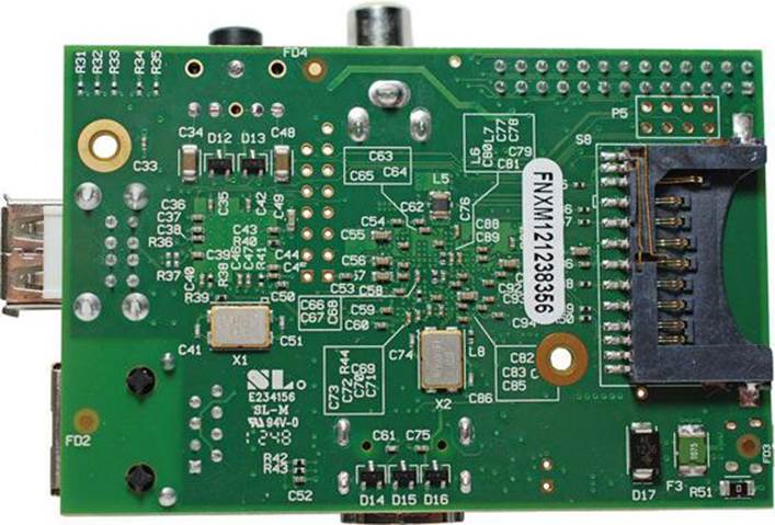
FIGURE 2.1 The back side of the Raspberry Pi Model B board.
That’s quite a web of traces and solder joints, wouldn’t you agree?
Recall from Chapter 1, “What Is the Raspberry Pi,” that the heart and soul of the Pi is the system on a chip (SoC, pronounced sock) called the Broadcom BCM2835. Actually, the SoC is an IC that is sandwiched between the PCB (below) and the RAM memory chip (above). You can see the SoC/RAM chip duo in the dead center of the Raspberry Pi PCB; see Figure 2.2 for details.
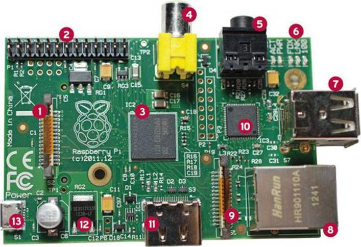
FIGURE 2.2 The front side of the Raspberry Pi Model B board.
1. DSI video
2. GPIO
3. CPU/GPU/RAM
4. RCA video
5. Stereo audio
6. Status LEDs
7. USB
8. Ethernet
9. Camera
10. USB/Ethernet controller
11. HDMI
12. Voltage regulator
13. Power Micro USB
The Foundation decided to stack the memory IC on top of the Broadcom SoC to save space on the board. That it does, I must say.
The processor is the mathematical muscle of any computer system. The Pi features an ARM11 processor that runs at a base speed of 700 megahertz (MHz). This means that the Pi (at least in theory) can execute 700 million instructions per second, although some instructions require a couple clock cycles.
Specifically, the ARM chip employs an instruction set called ARMv6. Some advanced hardware geeks complain that the Pi’s processor does not support the ARMv7 architecture that is featured in other ARM-equipped mobile devices such as the BeagleBone, but in my opinion, it has all the computing power needed for general-purpose enthusiasts.
Ultimately, the fact remains that the main day-to-day difference between ARMv6 and ARMv7 is that the latter is faster even at the same processor clock speed. We are also faced with the fact that the Raspberry Pi is somewhat more limited in the software that it runs due to the ARM version.
The ARM processor is used most widely in mobile devices; it is actually sort of novel for a personal computer such as the Raspberry Pi to run this chip. Unfortunately, the ARM architecture means that the Pi cannot run Windows or Mac programs (that is, on those systems that operate on the Intel/AMD 32- and 64-bit processor platforms).
Another point to consider about the Broadcom BCM2835 is that the SoC delivers not only the ARM central processing core, but also the onboard video processor—remember that SoC stands for system on a chip. As it happens, the BCM2835 includes the VideoCore IV GPU (pronouncedgee-pee-you), which stands for graphics processing unit.
So, in other words, the SoC contains two “brains”—the main ARM processor for general-purpose number crunching and the VideoCore IV GPU for video graphics display. What’s especially cool about the VideoCore IV is that it can decode and play full 1080p high definition (HD) video by using the vendor-neutral industry standard H.264 codec.
You learn in Chapter 18, “Raspberry Pi Overclocking,” how you can adjust the memory split between system memory and graphics memory. Doing so optimizes the Pi for particular types of applications and uses.
The Hidden Cost of Owning a Raspberry Pi
As you already know, your $25 or $35 gets you a Raspberry Pi PCB and nothing else. This comes as a surprise to many people, so I want to give you all the prerequisites as early in the game as possible.
At the very least, you’ll need to purchase or otherwise obtain the following hardware to get started with your Raspberry Pi:
![]() Micro USB Power Supply
Micro USB Power Supply
![]() SD Card
SD Card
![]() Powered USB hub
Powered USB hub
![]() Ethernet cable
Ethernet cable
![]() Monitor
Monitor
![]() Video cable
Video cable
![]() Audio cable
Audio cable
![]() USB keyboard and mouse
USB keyboard and mouse
The keyboard, mouse, and monitor/cable are technically optional if you plan to run the Raspberry Pi “headless” (headless Pi setup is covered in Chapter 7, “Networking Raspberry Pi”).
Now let’s explain each of these required hardware components in greater detail.
A 5V Power Supply
The Raspberry Pi expects an incoming electrical voltage of 5 volts (V) ±5% per the USB 2.0 standard. I mention the Universal Serial Bus (USB) here because power to the Pi is derived from a USB-based power supply. From there the Pi’s electrical requirements depend on which board you have:
![]() Model B: 700 milliamps (mA) at 3.5 watts (W) or
Model B: 700 milliamps (mA) at 3.5 watts (W) or
![]() Model A: 500 mA at 2.5 W
Model A: 500 mA at 2.5 W
Note: A Real Power Saver
The dramatically less power that Model A requires represents the board’s chief attraction among electronics enthusiasts. We can build super low-power projects with Model A that would be nearly impossible to do with Model B. The reason for Model A’s lighter power consumption footprint has to do principally with the absence of the SMSC LAN9512 Ethernet controller, which pulls quite a bit of power on its own. On the other hand, remember that if you plug a USB Wi-Fi dongle directly into the Pi, power consumption goes up correspondingly.
The power port on the Raspberry Pi PCB is the Micro USB B-style interface; therefore, a Pi-compatible power supply uses the standard USB A connector on one side and the Micro USB B connector on the other side. I show you my own Raspberry Pi power supply in Figure 2.3.
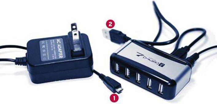
FIGURE 2.3 A Raspberry Pi-compatible power supply on the left (Micro USB plug is labeled 1) and a powered USB hub on the right (Standard USB plug is labeled 2).
It is crucial for you to understand that although the Raspberry Pi expects 5V of power incoming to the board, the board internally operates at a much lower 3.3V. This power step-down is accomplished automatically by virtue of the Pi’s on-board voltage regulator and C6 capacitor.
Not to get too geeky with the electronics (I’ll work up to that stuff gradually throughout this book), a capacitor is an electronics component that stores an electrical charge temporarily. If you examine the barrel-shaped object in Figure 2.2 just to the rear of the Micro USB interface, you’ll see the C6 capacitor. By the way, C6 refers to the PCB label for this component.
The C6 capacitor is really quite cool. It ensures that the incoming 5V is smooth and steady. If you have a cheap power supply that dips or spikes every so often, the capacitor can step in and even out the voltage flow. Pretty neat!
When the Pi’s circuitry has been expanded to, say, a microcontroller board or a breadboard, you need to keep voltage regulation at the forefront of your mind to avoid overpowering the Pi and causing irreversible damage.
In Chapter 4, “Installing and Configuring an Operating System,” I recommend that you stick to known name brands when you choose a Secure Digital (SD) card for your Pi’s operating system. You’ll want to follow this rule when choosing a power supply as well.
Some of my colleagues and friends have been burned by purchasing off-brand “Raspberry Pi-compatible” power supplies from eBay or Craigslist vendors. The main problem with cheap power supplies is that they don’t deliver a solid 5V of direct current (DC) to the PCB. If the power supply delivers too much juice, the board can fry. If the power supply doesn’t deliver enough power, the Pi will shut down at worst and operate erratically at best.
The following are a few third-party vendors who do produce reliable Raspberry Pi-compatible power supplies:
![]() AdaFruit (http://is.gd/klOOWr)
AdaFruit (http://is.gd/klOOWr)
![]() ModMyPi (http://is.gd/Tme3iq)
ModMyPi (http://is.gd/Tme3iq)
![]() SparkFun (http://is.gd/rs6UJx)
SparkFun (http://is.gd/rs6UJx)
SD Card
The Secure Digital (SD) card is a solid-state removable storage device that is needed because the Pi has no permanent, onboard data storage capability.
You learn how to flash Raspberry Pi firmware and a Linux operating system to the SD card in Chapter 4. For now, however, just know when you start shopping that you are looking for the following items:
![]() A standard SD card. (The SD specification consists of the Standard, Mini, and Micro form factors. You can use an adapter to convert a Mini or a Micro SD card into a Standard size.)
A standard SD card. (The SD specification consists of the Standard, Mini, and Micro form factors. You can use an adapter to convert a Mini or a Micro SD card into a Standard size.)
![]() A brand name product, rather than cheaper, generic options. Some of the SD card brands I trust include Kingston (http://is.gd/j9kb1O), Transcend (http://is.gd/Jwxe1N), and SanDisk (http://is.gd/2NZw8b).
A brand name product, rather than cheaper, generic options. Some of the SD card brands I trust include Kingston (http://is.gd/j9kb1O), Transcend (http://is.gd/Jwxe1N), and SanDisk (http://is.gd/2NZw8b).
![]() Capacity of at least 4 GB
Capacity of at least 4 GB
![]() Class 4 or higher
Class 4 or higher
The speed class rating of an SD card is a relative indicator of how quickly the card can read and write data. Do you remember the old CD burners with their 2x, 4x, 48x nomenclature? Same thing here. A Class 2 spec exists, but I would stick with one of the following SD speed classes:
![]() Class 4: 4MB/sec
Class 4: 4MB/sec
![]() Class 6: 6MB/sec
Class 6: 6MB/sec
![]() Class 10: 10MB/sec
Class 10: 10MB/sec
You’ll find that opinions vary widely regarding which SD card brand(s) or speed(s) is optimal. My best advice to you is to try out a few models and speed ratings with your equipment and let your own intuition and Pi benchmark results be your guide.
Standard-sized SD cards come in two varieties: Secure Digital High Capacity (SDHC) and Secure Digital eXtended Capacity (SDXC). The main difference is that SDHC cards go up to 32GB, and SDXC cards go up to 2TB. If I were you, I would check the Raspberry Pi compatibility list athttp://is.gd/Ym6on0 before I shell out the money for a top-of-the-line, highest-capacity, speediest card. Sometimes it is best to go for compatibility instead of potential performance.
Powered USB Hub
The Model B board includes two USB ports, but please don’t let that “security” lull you away from the reality that you truly need to purchase a powered USB hub. Some Raspberry Pi newcomers use the two USB ports for keyboard and mouse connections and then scratch their heads in wonderment when they realize, “How the heck can I plug in something else to the Pi?”
A hub is a compact device that hosts several USB A-type devices. The “powered” part is important inasmuch as USB hardware has in itself a current draw. Thus, we need to ensure that our USB hub can supply not only the 700 mA required by the Pi board, but also any power requirements for USB-attached peripherals.
Actually, that point bears repeating: Ensure that any power supply that you consider for your Pi supplies at least (but hopefully more) than 700 mA. Non-self-powered USB peripherals will each draw 100 mA or so from the USB ports on your Pi. To be sure, you should consider a powered USB hub as a “must have” peripheral for your Pi.
Something else: The power supply and a powered USB hub are two separate pieces of hardware and serve different purposes. The USB power supply gives power to the Raspberry Pi itself and allows it to function. A powered USB hub enables you to expand the Pi’s functionality by adding more hardware and giving power to those additional devices rather than to the Pi.
You can see what my own powered USB hub looks like by examining Figure 2.3.
Ethernet Cable
If you want to connect your Pi to the Internet (and why wouldn’t you want to do that?), you’ll need an Internet connection and a Category 5e or 6 Ethernet cable. The Model B board includes an onboard RJ-45 Ethernet jack, into which you plug your new cable. You plug the other end of the cable into a free switch port on your wireless router, cable modem, or Internet connectivity device.
Note: Connectors and Ports
In physical computing, a port or jack is the connection interface on the computer. The perimeter of the Raspberry Pi, for example, is lined with ports of different varieties.
A plug or connector is the part of a cable that plugs into a port. For instance, a Category 6 Ethernet cable uses an RJ-45 connector to plug into the RJ-45 jack on the edge of the Raspberry Pi Model B board.
“But what about Wi-Fi?” you ask. Wi-Fi and all other network-related questions are addressed in Chapter 7. For now, understand that if you have a Model A board, your only option for traditional wired Ethernet networking is to purchase a USB wired Ethernet adapter. Again, more on that subject later on in the book.
The subject of Wi-Fi connectivity bears on what we just covered vis-a-vis USB ports and powered USB hubs. That is to say, we must use a USB Wi-Fi dongle in order to give wireless Ethernet connectivity to our Raspberry Pi device.
Monitor
Unless you plan to run your Raspberry Pi remotely in a so-called headless configuration, you need to set aside a spare monitor or television for use with your Pi. Yes, you heard me correctly: You can plug your Pi into any television, be it an older model (via an old-school yellow RCA plug) or a modern HD display using the HDMI interface.
In fact, one of the Raspberry Pi Foundation’s goals in designing the Pi was to support “any old” television set as a cheap display device. Remember that the Foundation’s philosophy is to make the Raspberry Pi as inexpensive and easy as possible for people to get their hands on and to start programming.
Note: Tiny Little Screens
Some Raspberry Pi enthusiasts translate the tiny footprint of the Pi board into the monitor as well. To that point, you can purchase small (think GPS-sized) color monitors from a number of online retailers. For instance, check out this adorable 7-inch diagonal HDMI display from AdaFruit: http://is.gd/GJARAZ
Cables
Depending on what type of monitor or TV you have at your disposal, you might need to purchase an analog RCA video cable or a digital HDMI cable. The good news is that these cables are almost ubiquitous and are quite inexpensive.
As you learn in more detail momentarily, the use of an HDMI cable means that you don’t have to worry about providing audio-out capability in your Pi with an analog audio cable. However, if you’re using the RCA video cable and do need audio, you’ll need to buy a 3.5mm stereo audio cable as well.
Note: HDMI with Dedicated Audio
In case you were wondering, it is possible to configure the Raspberry Pi to use the HDMI cable for video and the 3.5mm stereo audio cable for audio. To do so, you must instruct the Pi to disable the HDMI audio channels by running the command sudo amixer cset numid=3 1 from a Raspbian shell prompt. By the way, Raspbian is the official Linux distribution of the Raspberry Pi; we’ll learn all about it beginning in Chapter 4.
USB Keyboard and Mouse
The good news is that the power draw for USB keyboards and mice is low enough that you can plug them directly into the USB interfaces on the Model B board. The bad news is that you won’t have any additional expandability for your Pi. Therefore, your best bet is either to invest in the previously described powered USB hub or connect to your Pi remotely.
Figure 2.4 shows a Raspberry Pi all plugged in.
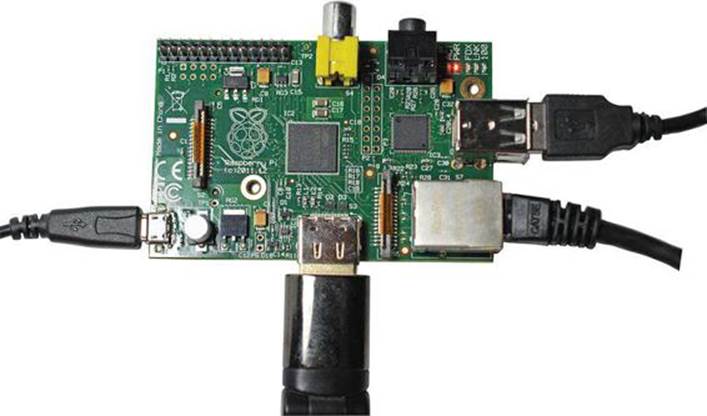
FIGURE 2.4 A Raspberry Pi, fully connected and ready to go!
Caution: Just in Case
As you can see in Figure 2.4, a “naked” Raspberry Pi, especially when it’s all cabled up, is quite vulnerable to your physical environment; this includes electrostatic discharge (ESD) as well as physical factors. For these reasons you should consider purchasing a case for your Pi. You read about cases in more detail in Chapter 3, “A Tour of Raspberry Pi Peripheral Devices.” Even with a case, however, you should take steps to avoid ESD when interacting with the Pi hardware. You can do this by using an antistatic wrist strap whenever you handle the bare Pi board.
A Tour of the Model B Board
Now, let’s commence our tour of the Model B board. The tour begins with the lower-right of the board from the perspective in Figure 2.2.
Networking
The cube-shaped module on Model B is the onboard Registered Jack 45 (RJ-45) Ethernet interface. As some of you might know, wired Ethernet is capable of running at data transmission speeds of 10, 100, and even 1000 megabits per second (Mbps).
However, because the Raspberry Pi Ethernet interface operates using the USB 2.0 standard, the jack is limited to either 10 or 100 Mbps. As long as you purchase a Category 5e or 6 Ethernet cable and your network already operates at 100 Mbps, the Pi should work at that speed with no problem at all.
Video and Audio
In my opinion, the preferred way to handle outgoing video and audio is to employ the Pi’s integrated High Definition Multimedia Interface (HDMI) port. The number one reason is that HDMI carries both video and audio signals. And number two, the signaling is entirely digital. HDMI is the way to go if you plan to use your Raspberry Pi as a multimedia center because you have access to full HD 1920x1080 screen resolution.
The only possible downside to using HDMI is that only later-model computer monitors support the interface. Many LCD monitors still in wide use only support DVI connectors. In this case, you still have a couple options: First, you can plug your Pi into your HDMI-compatible television; second, you can buy an HDMI-to-DVI-D converter plug and connect the Pi to your Digital Video Interface (DVI-D) -equipped computer monitor; this is shown in Figure 2.5. Of course, if you do this you lose the ability to carry audio as well as video.
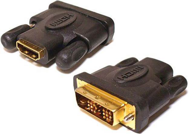
FIGURE 2.5 You can easily convert an HDMI connection to a DVI-D connection.
Note: VGA Need Not Apply
The 15-pin Video Graphics Array (VGA) port that is found in older monitors is incompatible with the Raspberry Pi.
The yellow circular jack opposite to the HDMI port on the board is what is called the RCA connector and forms the video feed portion of an old multimedia standard called composite video. Although this plug allows you to connect your RasPi to ancient television sets, the signaling is analog, the video capability is standard-definition only, and there is no signaling left over for audio.
Model B includes a third video interface just to the left of the Raspberry Pi logo called the Display Serial Interface, or DSI. This display interface is used primarily for tablet or smartphone touch screens (remember that the ARM architecture in general is slanted heavily toward the smartphone market). As of spring 2013, little is published on how to make use of the DSI interface. Recall that we don’t have full access to the VideoCore IV GPU, so we mere mortals cannot yet develop a kernel-mode driver for this interface. Keep your eyes peeled online because I’m sure we’ll see development in this area before too long.
As an alternative to HDMI audio, the Raspberry Pi includes a 3.5 mm stereo audio jack. This means you can connect computer speakers or perhaps headphones to your Pi to receive analog audio from the board.
Storage
Many Raspberry Pi newcomers are befuddled as to where to connect their SD cards to the board. You’ll find that the SD card slot is a bare-bones port that is actually mounted underneath the PCB. Thus, you line up the SD card on the interface rails and gently push the card until it is fully seated on the interface pins.
Don’t worry that the SD card sticks out from the side of the Pi a little bit—that behavior is by design to facilitate card removal. Actually, the fact that SD card pokes out from beneath the PCB is yet another reason for you to invest in a Raspberry Pi case.
With respect to volatile (nonpermanent) storage, don’t forget about the 512MB random access memory (RAM) chip that is stuck directly on top of the SoC at the center of the PCB. Recall also that the Model A board includes a 256MB RAM chip.
Power/Status Information
The Micro USB power port intends to supply 5V of direct current (DC) to the board from your external power supply. Recall, however, that the Raspberry Pi operates at an internal voltage of 3.3V. The good news is that the Pi board includes an onboard voltage regulator (located behind the Micro USB port in the location marked RG2), as well as the C2 capacitor to smooth out the voltage.
In one corner of the Model A or Model B board, next to the stereo audio jack, you’ll observe a bank of light emitting diodes, or LEDs (see Figure 2.6). These LEDs light up to denote the following status conditions:
![]() ACT (Green): SD Card Access
ACT (Green): SD Card Access
![]() PWR (Red): 3.3 V power present
PWR (Red): 3.3 V power present
![]() FDX (Green): Full Duplex LAN connected
FDX (Green): Full Duplex LAN connected
![]() LNK (Green): LAN link activity
LNK (Green): LAN link activity
![]() 100 (Yellow): 100Mbps LAN connected
100 (Yellow): 100Mbps LAN connected
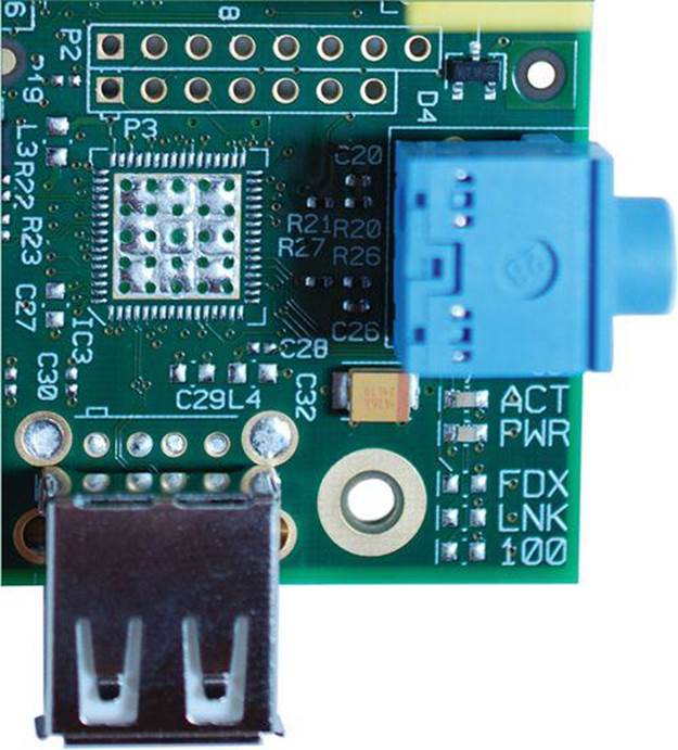
FIGURE 2.6 LEDs give you at-a-glance status information from your Raspberry Pi. In this image, notice the bank of LEDs in the lower right corner of the PCB.
Remember that you can tell at a glance whether you have a Revision 1 or Revision 2 board by examining the label of the first LED. If the LED is labeled ACT, you have a Revision 2 board. If the label reads OK, you have a Revision 1 board.
Camera
The Model B board includes a Mobile Industry Processor Interface (MIPI) Camera Serial Interface (CSI) connector; the interface is located just behind the Ethernet port and connects to the Raspberry Pi camera board that the Foundation released in May 2013.
The heart of the Raspberry Pi camera module is a 5 megapixel (MP) Omnivision OV5647 sensor that shoots still images at a 2592x1944 pixel resolution and records 1080p/30 frames-per-second video.
The Foundation sells the camera board through its usual distribution partners for $25. The use of the camera module is covered in great detail in Chapter 16, “Raspberry Pi Portable Webcam.”
Processing
As previously discussed, at the center of the Raspberry Pi Model B board is a two-layer integrated circuit (IC) stack called a chipset. On top is a 512MB random access memory (RAM) module. At the bottom is the Broadcom BCM 2835 SoC.
Remember that the SoC consists of two processor cores: a 700 MHz central processing unit (CPU) that is used for general computing tasks and a VideoCore IV graphics processing unit (GPU) that is used for, well, video generation.
Expansion
Okay—I’ve saved the best for last. On the same side of the board as the status LEDs but on the opposite end is a bank of 26 copper header pins called the General Purpose Input/Output (GPIO) interface.
The GPIO is critically important to the Raspberry Pi because these pins represent the way we can expand the Pi board to interact with external hardware such as microcontrollers, motors, robotics—you name it!
You learn the specific purpose of each GPIO pin—called, appropriately enough, the pinout—in Chapter 19. In the meantime Figure 2.7 provides you with an illustration of how you can use the GPIO header.
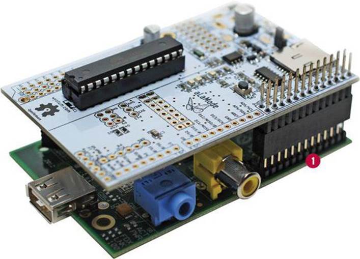
FIGURE 2.7 You can leverage the Pi’s GPIO pins (marked 1) to work with expansion boards such as the Alamode (http://is.gd/6eMMnC). The Alamode is an Arduino clone that can broaden and deepen the capabilities of the Raspberry Pi.
It seems the subject of Raspberry Pi cases has arisen several times in this chapter. I advise you to be choosy when selecting a case for your Pi. Some cases look cool but actually can heat up your Pi board due to insufficient venting. Moreover, I’ve seen some Pi cases that make it difficult or impossible for you to access the GPIO pins with the case in place.
I have had good luck with Raspberry Pi cases purchased from Adafruit (http://is.gd/K1Ow9s), the Pi Hut (http://is.gd/hR22tW), and ModMyPi (http://is.gd/xT8LTA).
Next Steps
I hope you are now more comfortable with the Raspberry Pi hardware. Now that you understand how the Raspberry Pi board is set up, you probably want to know more about the extra hardware that can be plugged into your Pi to expand its capabilities. To that point, let’s dive into a detailed consideration of Raspberry Pi peripheral devices.
All materials on the site are licensed Creative Commons Attribution-Sharealike 3.0 Unported CC BY-SA 3.0 & GNU Free Documentation License (GFDL)
If you are the copyright holder of any material contained on our site and intend to remove it, please contact our site administrator for approval.
© 2016-2026 All site design rights belong to S.Y.A.