Raspberry Pi Projects (2014)
Part III. Hardware Projects
Chapter 13. Home Automationby Jonathan Evans
In This Chapter
• Interface the following sensors to the Raspberry Pi: door switch, motion sensor and temperature gauge
• Create e-mail alerts that can be used with each project in this chapter
• Convert a webcam into a surveillance camera that records footage and takes pictures when motion is detected
• Control the Raspberry Pi using a radio frequency remote key fob
In this chapter you will be creating some home-automation projects to make your home environment more intelligent and provide you with the foundational knowledge to further the automation of your home. A key part of home automation is being able to interface with sensors. This is something that the Raspberry Pi is very good at. There has been a recent explosion of cheap and reliable sensors available to the DIY enthusiast, and combined with the small form factor of the Pi, its high processing power, network connectivity and low cost, it makes the Raspberry Pi an ideal platform for the DIY home-automation enthusiast.
Home automation can be distilled into three categories: control, alert and monitor. During the course of this chapter, you will create five projects covering each of these categories.
In this chapter you will not be making use of PiFace, which is used in other chapters in this book. You will interface directly with the GPIO ports of the Raspberry Pi using male-to-female jumper wires (described later). If you have to remove your PiFace, remember to always power down the Raspberry Pi before disconnecting (or connecting) anything to the GPIO headers.
The Internet Of Things
The Internet Of Things (IOT) describes the rapidly expanding phenomenon of connecting things to the Internet. Network connectivity and IP addresses are no longer just used to connect computers. Increasingly we are seeing everyday appliances and sensors connecting to a network, providing us with real-time information from, and control over, those devices. The IOT is an emerging technology, so as it matures and interoperability standards are developed it will become easier and cheaper to connect devices to the IOT which will have a positive impact on home owners wanting to automate their environment. Again the Raspberry Pi has a role to play in connecting devices cheaply to a network. As you work through this chapter you will be contributing to the rapidly expanding network of things connected to the IOT.
Project 1: How to Create a Motion Sensor and Door Switch
In your first home-automation project you will create a motion sensor and door switch. Motion sensors and door switches allow you not only to create alarms or alerts, but also to monitor flow and movement throughout your home. Using the information created by these sensors, you can apply rules and actions using Python. For example, you could turn off a light in a room if motion is not detected for a period of time, or send an e-mail alert to yourself if your garage door is open for a period of time. So by combining sensors, rules and actions, you can create a more intelligent home environment.
A door switch contains a reed switch (see Figure 13.1) that is triggered when the two pieces come apart. One piece is attached to the door and the other to the door frame. One of the two halves contains a magnet and the other a reed switch that is held closed when the magnet is near. When the two come apart the magnetic field loses its strength, and the switch is broken. This type of switch is closed when the pieces are together and open when they come apart. So when the door is closed current flows through the switch, and when the door is open the current is broken. This type of switch is called normally open. The motion sensor, sometimes known as a passive infrared (PIR) sensor (see Figure 13.2), is packaged with an integrated circuit and a lens that will focus the moving objects for the sensor. A motion sensor is also normally open, so both of the sensors interact with the Raspberry Pi through the GPIO port in the same manner, which makes the software for both identical. You will be writing some Python script to monitor the sensors and produce an action when either sensor is triggered. In this tutorial you will trigger a message to the screen, but you could take any number of other actions as explained before.
Figure 13-1: A door switch.
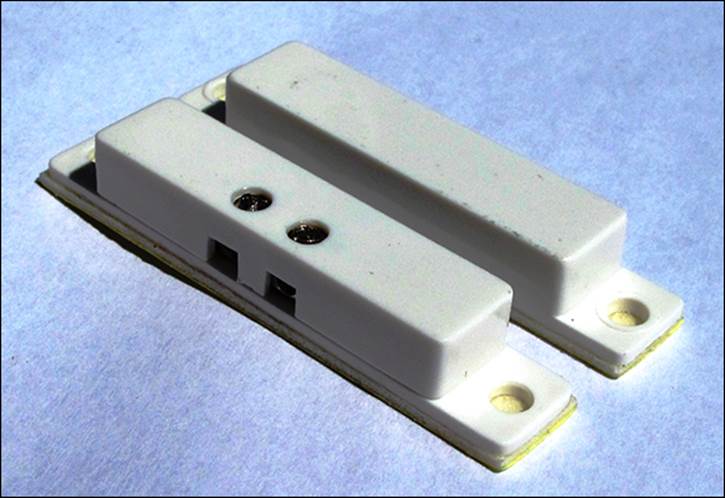
Figure 13-2: A motion sensor.
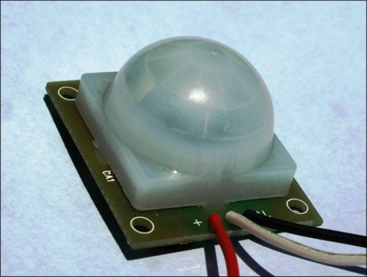
Table 13.1 shows what you need.
Table 13-1 What You Will Need
|
QTY |
Item |
Description |
|
1 |
Door switch |
Can be obtained from a home security outlet or online. |
|
1 |
Motion sensor |
Usually 5V-12V with three terminals, +VE, GND and 3.3V Pi-friendly output. |
|
2 |
10kΩ resistors |
Brown, black, red, gold. |
|
2 |
1kΩ resistors |
Brown, black, orange, gold. |
|
1 |
Solderless breadboard |
A prototyping board for which parts and wires can be connected by clipping them into the board. It is used for prototyping electronics without having to solder parts together. |
|
3, 5 |
Jumper wires |
Male to male for breadboard connections, male to female for connecting the breadboard to the GPIO pins. Jumper wires usually come in packs of various quantities, colours and sizes. Although you need only 8 for this project, having 20 to 30 of each should see you through most projects. Any size will do for this project, but shorter male to male (10 cm) and longer male to female (20 cm) are best. |
Construction
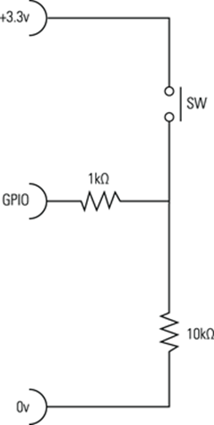
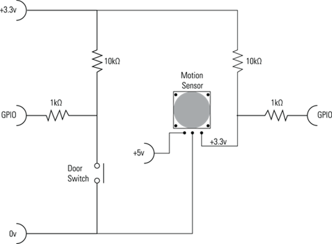
You are going to be using the Raspberry Pi GPIO ports to interface with the sensors. GPIO ports can be configured for input or output. In this case you are going to use them for input as you are collecting data from an external sensor. A GPIO port can have three different states: high (positive), low (ground) or floating (either). For you to be able to accurately determine the state of the GPIO pin, you need to tie it either to positive or negative (ground). You do this using what is known as a pull-up or pull-down resistor. When the GPIO is connected to a positive current the GPIO pin’s value is high. When it is connect to ground it is low. Figure 13.3 shows a pull-up resistor (10kΩ) that connects the GPIO to positive when the switch is open. However, when the switch closes there is a lower resistance path to ground, and the GPIO state will go low. Figure 13.4shows a pull-down resistor (10kΩ) connecting the GPIO pin to ground, making it low. When the switch is pressed there is a lower resistance to positive, which changes the GPIO state to high. The 1kΩ resistor is there to protect the GPIO pin from a short circuit when the switch is pressed.
![]()
Always double-check your circuits before powering on the Raspberry Pi. You can very easily damage the Raspberry Pi by not protecting the GPIO pins with resistors. Be especially careful of the 5V pins, which if connected to a GPIO pin will cause permanent damage.
In your project you want a closed circuit (low state) when the door is closed or when there is no motion and a high state when the door is opened or motion is detected, so you want a pull-up resistor to set the GPIO high in an alarm state. You will therefore base your circuitry on the diagram inFigure 13.3.
Figure 13-3: A circuit showing a pull-up resistor.
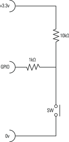
Figure 13-4: A circuit showing a pull-down resistor.
The PIR sensor has three coloured wires: ground, positive and alarm. The colours and pin positions may differ, depending on which one you buy, so be sure to check the data sheet of your PIR. The alarm pin is an open collector, meaning you will need to connect a pull-up resistor on the alarm pin (see Chapter 9, “Test Your Reactions”, for details on open collectors).
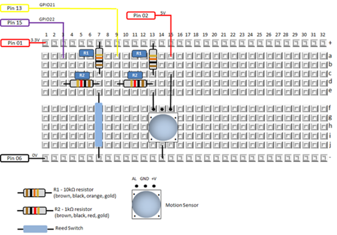
In Figure 13.5 you can see the circuit diagram with all the components, and in Figure 13.6 there is the breadboard prototype diagram.
Figure 13-5: A circuit diagram for the door switch and motion sensor connected to two GPIO pins on the Raspberry Pi.
Software
The software will print to the screen whenever motion is detected or the door sensor is triggered. You want to print to the screen only once per event, so you will use variables (motion and door) to keep track of when you are in an alarm state and prevent the trigger reoccurring for the same event. If you were logging these events to a database, or taking another action such as switching on a light or sending an e-mail alert, you would use this method to prevent multiple actions being created for the same event. The code is provided in Listing 13.1.
Figure 13-6: The breadboard layout of the reed switch and motion sensor connected to the Raspberry Pi.
Listing 13.1 Home Automation Using Motion Detection
#!/usr/bin/env python
"""
Home Automation using motion detection
For the Raspberry Pi
"""
import RPi.GPIO as GPIO
import time
GPIO.setmode(GPIO.BOARD)
GPIO.setup(13, GPIO.IN)
GPIO.setup(15, GPIO.IN)
def main():
motion = False
door = False
while True:
if GPIO.input(13):
if motion == False: print "Motion Detected"
motion = True
else:
motion = False
if GPIO.input(15):
if door == False: print "Door Opened"
door = True
else:
door = False
time.sleep(.3)
if __name__ == "__main__":
main()
Project 2: How to Monitor Your Home with a Webcam
Webcams have been around for quite some time, but when you combine one with the small form factor of the Raspberry Pi you can put surveillance easily anywhere in the home without having to run cables back to a recorder or PC. In this project you will construct a webcam surveillance monitor that will
• Stream real-time video to a browser
• Create e-mail alerts when motion is detected
• Create stills and video files when motion is detected
You can use this to increase the security of your home but also for other purposes, such as keeping an eye on the kids around the house, knowing whether you left the garage door open or receiving alerts and be able to see when someone walks through the front door. Table 13.2 shows what you need.
Table 13-2 What You Will Need
|
QTY |
Item |
Description |
|
1 |
Webcam |
Most webcams will work, but a good frame rate (30 fps), autofocus and screen resolution (640 x 480) are webcam features that will all add to the quality of the picture. |
|
Network connection to the Raspberry Pi |
A network connection is needed for the video streaming. You will most likely want a Wi-Fi connection so that you can place your webcam where you need it. Configuring a USB Wi-Fi device for your Raspberry Pi is beyond the scope of this tutorial; however, there are a number of online resources available on how to do this. If you have an Ethernet network point, that will work fine too. |
|
|
An Internet connection for your Raspberry Pi |
You will need this to install the webcam software. |
![]()
Visit this website to check for compatibility of your webcam, or any other hardware, with the Raspberry Pi: http://elinux.org/RPi_USB_Webcams.
Construction
The USB webcam plugs into the USB port of the Raspberry Pi, and the Raspberry Pi is connected to your home network either via Wi-Fi or network cable. You need to be connected to the Internet at the time you install the webcam software, but you do not need an Internet connection for the webcam to store video footage or to stream on your home network. The video footage is stored directly on the Raspberry Pi and is streamed to a predefined port. If you don’t know what a port is, don’t worry; it’s like a television channel that the Raspberry Pi will broadcast to. You will use a browser to tune into that channel (port) to view the live video stream. You will be able to view the video using any browser-enabled device (PC, tablet, smartphone) connected to your home network. You will not be able to view the video footage from the Internet without opening up the port on your router. Your router will typically only allow traffic from the Internet to pass through port 80, which is used for Internet browsing and e-mail. However, you can configure your router to open up the port you choose for video surveillance. I’ll explain that in more detail later in the “How to View the Webcam over the Internet” subsection of this project.
You will most likely want to run your Raspberry Pi headless (without a TV, keyboard and mouse attached). If you are not familiar with how to do this, I advise you to do some research and become comfortable with accessing your Raspberry Pi remotely. It is not difficult; you just need to know the IP address of your Raspberry Pi and then unplug the TV, keyboard and mouse and access it using a remote access SSH application such as Putty.
![]()
You can find the IP address of your Raspberry Pi by typing
/sbin/ifconfig | less
The output will look something like this:
wlan0 Link encap:Ethernet HWaddr d8:eb:97:18:16:ef
inet addr: 192.168.0.2 Bcast:192.168.0.255 Mask:255.255.255.0
Your IP address is the number provided after inet addr:, which in this case is 192.168.0.2.
Software
You will be using a great piece of open-source software to do all of this called Motion. Motion was founded by Jeroen Vreeken and has since had over 100 people contribute to the code. At the time of this writing, Motion is being maintained by Kenneth Lavrsen and Angel Carpintero atwww.lavrsen.dk/foswiki/bin/view/Motion/WebHome. Installing Motion requires that you run a command from the command prompt on your Raspberry Pi. Unless you are familiar with assigning permissions in Linux, I recommend that you use the root user and not the standard user for this project.
![]()
You can create the root user by typing
sudo passwd root
The system will prompt you for a password twice. After that is complete log in to your Raspberry Pi using root as the username and the new password you just set.
After you are logged in as the root user, your command prompt should look like this:
root@raspberrypi:~#
If you have not done so recently, you should make sure that your Raspberry Pi is up to date by typing
sudo apt-get update
sudo apt-get upgrade
These updates will take some time to complete. You are now ready to install Motion. At the command prompt type
sudo apt-get install motion
The install process is automatic and should complete in a few minutes (depending on your Internet connection speed). After this is complete you are ready do to some configuration. In order to configure Motion, you will need to be able to edit a file in Linux. If you are familiar with editing in Linux, you can use your favorite editor; otherwise, you will be using a very simple text editor called nano. Table 13.3 shows the commands you will use for editing. You can refer to this table as needed.
Table 13-3 Nano Editing Commands
|
Action |
Command |
|
Start editing a file called filename |
nano filename |
|
Navigate |
Use the up, down, left and right keys. |
|
Exit and save |
Ctrl + X, followed by Y, followed by pressing the Enter key. |
|
Exit without saving |
Ctrl + X, followed by N. |
|
Search for text |
Ctrl + W, followed by entering the text that you want to search for, followed by pressing the Enter key. To search again for the same text, press Ctrl + W, followed by the Enter key. |
The installation process will have placed a configuration file in the /etc/motion directory. Edit the configuration file by typing the following at the command prompt:
nano /etc/motion/motion.conf
A screen similar to Figure 13.7 will appear.
Figure 13-7: The configuration file for Motion.
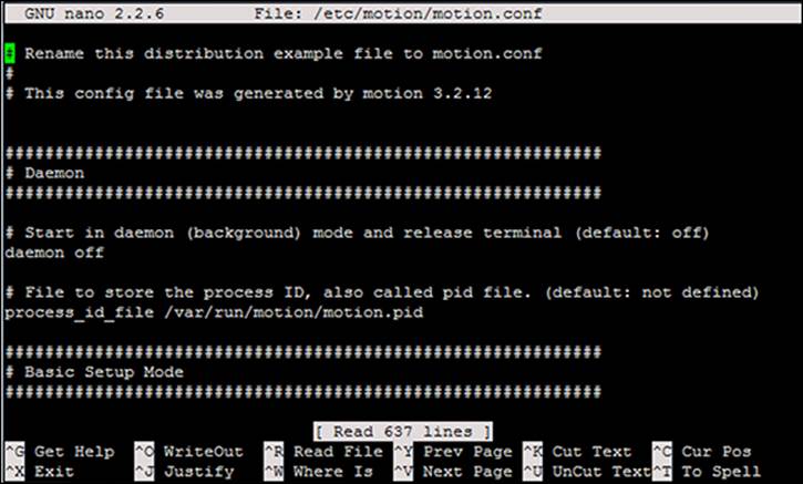
The first configuration you want to change will make Motion run in daemon mode, which will make sure that it is always running in the background. This means if you log off from your Raspberry Pi, the webcam will still run as long as it is plugged into power. You will see a setting calleddaemon close to the top of the configuration file. Change the setting from off to on. Then continue to make the configuration changes in Table 13.4.
Table 13-4 Motion Configuration Changes
|
Configuration |
New Value |
Comment |
|
framerate |
30 |
|
|
threshold |
500 |
|
|
gap |
10 |
|
|
max_mpeg_time |
30 |
|
|
output_normal |
center |
|
|
ffmpeg_video_codec |
msmpeg4 |
For viewing video footage in Windows; otherwise choose your preferred codec. |
|
target_dir |
/home |
You can choose any other directory where you want your video footage to be stored. |
|
webcam_motion |
on |
|
|
webcam_maxrate |
30 |
|
|
webcam_port |
8085 |
Or any other port. |
|
webcam_localhost |
off |
Save the file and exit (Ctrl + X, Y, Enter) to complete editing the configuration. After you’re back at the command prompt you need to restart Motion so that the new configuration can take effect. You do this by typing the following:
service motion stop
motion
If your webcam has an activity light on it, you should have noticed it come on. Check that it is working by doing a directory listing of the /home directory (type dir /home) and see if there are .avi and .jpg files being written. It is configured so that it will store video footage only when motion is detected, and it will store a maximum of 30 seconds of footage per file. You probably noticed when you were editing the configuration that this application is highly configurable and can be changed to suit your needs. Next you will test that the real-time video streaming is working.
Open a browser other than Internet Explorer on a PC, tablet or smartphone connected to your home network. (Internet Explorer does not support MJPEG streaming, so you need to use another browser such as Chrome, Firefox or Safari.) Now type the IP address and port of your Raspberry Pi. For example, type something like this:
http://192.168.0.2:8085
The real-time webcam video will now appear in the browser.
In order to view the video and picture files that have been saved in the /home directory, you have a number of options. I recommend connecting remotely to the Raspberry Pi using an FTP client (such as FileZilla) and then either copying the footage to a PC or executing the file directly through FileZilla (which actually copies the file across to the PC, runs it and then destroys the local copy).
How to Send an E-Mail When Motion Is Detected
One of the great features of Motion is the ability to run a Python script when movement is detected. Later in this chapter, there is a project describing how to send an e-mail. (See the section “Project 4: How to Send an E-mail Alert”.) You can use the code from that project to have an e-mail sent to you when movement is detected on your webcam. You can do this by editing the configuration file and looking for a configuration called on_event_start, which can be configured as follows:
on_event_start sudo python /home/sendemail.py 'Webcam ![]()
motion detected'
This configuration tells Motion to execute the sendemail.py script when movement is detected. The content of sendemail.py is located in the section “Project 4: How to Send an E-mail Alert” later in this chapter. You can also learn how to attach a file to an e-mail in that project, which allows you to e-mail a picture from the webcam when movement is detected. For this there is another configuration called on_picture_save. Set this configuration as follows:
on_picture_save sudo python /home/emailphoto.py 'Webcam ![]()
picture attached' %f
This configuration tells Motion to execute the emailphoto.py script, which is located in the /home directory, when movement is detected. Additionally, it passes a parameter (%f) to the script of the filename of the picture that the webcam took at the time the movement was detected. Motion will replace %f with the filename of the picture it took.
Both of these scripts are listed in project 4 of this chapter.
Remember, of course, to restart Motion after any configuration change by typing the following:
service motion stop
motion
How to View the Webcam over the Internet
This subsection comes with a big security warning. If you open up your Raspberry Pi to the Internet, anyone on the Internet can see your webcam. They will of course need to know your IP address and port, so you do have some measure of safety, albeit fairly weak. Internet hackers look for open ports, so it won’t be long before they figure out that there is a video stream on that port.
So if you are still reading this, this is how to make your webcam visible from the Internet. In a typical home installation there is a router that connects all the PCs and Wi-Fi devices in the house to the Internet. You need to configure your router to allow the video stream through the port you configured earlier in this project. Getting access to your router requires that you know how to do this, and may require that you contact your Internet service provider (ISP) or cable company. You will need to know the IP address of your router. Many routers use the 192.168.0.1 or192.168.1.1 address as a default. Type your router IP address into a browser. This will take you to a login page where you need to log in to the router with the username and password for the router. It is beyond the scope of this chapter to provide you with detailed instructions for this part as there are many different routers, each with their own configuration applications. Look for “port range forwarding” or “port forwarding” settings, often under a “Gaming” menu. (Gamers need to open a port to be able to participate in peer-to-peer games over the Internet.) Add a new entry called rpi-web. FromPort=8085, ToPort=8085, IpAddress=(Raspberry Pi IP address). Take note of the Internet IP address of the router under the Gateway settings of the router. This is the address that has been assigned to you by your ISP, and you will use this address to access from the Internet. Now type http://InternetIPAddress:8085 into a browser connected to the Internet. This should take you to your webcam video stream. From time to time your ISP may recycle IP addresses, so you will need to repeat the earlier steps to determine your new IP address. Alternatively, most ISPs will sell you a static IP address.
![]()
Your webcam is now accessible to anyone accessing the Internet who knows your Internet address and port number. It’s a good idea to install a firewall on your Raspberry Pi to protect your computer from port scanners and other malicious programs. A firewall is basically a set of rules that limits or blocks incoming or outgoing web requests. One more thing you may want to protect against is Internet users attempting to access your SSH account by trying a dictionary attack against your password. There is a handy utility called Fail2Ban that monitors your log files for failed login attempts and temporarily blocks offending users. Detailed instructions on these precautions are beyond the scope of this book.
Project 3: How to Make a Temperature Gauge
In this project you are going to be using a DS18B20 sensor to detect the temperature and display it on the screen. You will also write some Python code to monitor temperature and send an e-mail alert if the temperature exceeds a predefined threshold. The sensor returns a Celsius value, so you will also have some optional Python code to do a Fahrenheit conversion if that is your preference. Table 13.5 shows what you will need.
Table 13-5 What You Will Need
|
QTY |
Item |
Description |
|
1 |
DS18B20 |
This sensor looks like a transistor but is actually a highly accurate 1 wire temperature sensor. |
|
1 |
4.7kΩ resistor |
A pull-up resistor. |
|
1 |
Solderless breadboard |
A prototyping board for which parts and wires can be connected by clipping them into the board. It is used for prototyping electronics without having to solder parts together. |
|
3, 3 |
Jumper wires |
Male to male for breadboard connections, male to female for connecting the breadboard to the GPIO pins. Jumper wires usually come in packs of various quantities, colours and sizes. Although you need only 6 for this project, having 20 to 30 of each should see you through most projects. Any size will do for this project, but shorter male to male (10 cm) and longer male to female (20 cm) are best. |
Construction
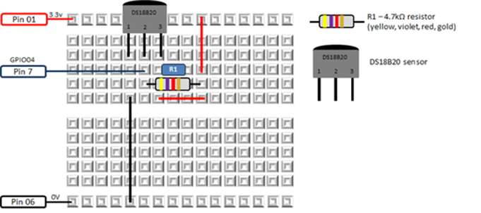
The circuitry for this sensor is very easy to build. Besides the power and ground connections all you need to do is connect the 4.7Ωk pull-up resistor between the signal and power as shown in Figures 13-8 and 13-9. It is important to use pin 7 for the sensor connection. The software you will use to interface with the DS18B20 is hard-coded for pin 7, so you cannot use another pin for this sensor.
Software
Luckily the software required to interface with the DS18B20 has already been written and is built into your Raspberry Pi kernel. You will be using an application called Modprobe to retrieve the temperature value.
At the Raspberry Pi command prompt type the following two commands:
sudo modprobe w1-gpio
sudo modprobe w1-therm
Figure 13-8: A wiring diagram for a DS18B20 temperature sensor connected to a Raspberry Pi.
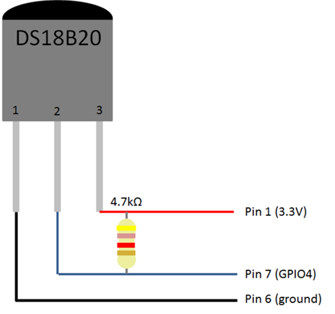
Figure 13-9: A breadboard diagram for a DS18B20 temperature sensor connected to a Raspberry Pi.
One of the nice features of the DS18B20 sensor is it has a unique number that allows you to use multiple sensors and uniquely identify the temperature of each sensor. The preceding command interfaces with the sensor and retrieves the temperature, which it then writes to a new directory on the Raspberry Pi. This directory can be found in /sys/bus/w1/devices/. In order to check if this file was created, you can do a directory listing by typing the following command:
ls /sys/bus/w1/devices/
You should see a directory that correlates to the unique number of your sensor. Every sensor has a unique number, so it won’t be the same as my file, but it will be similar to this:
28-0000040be5b6
If you don’t see a directory with lots of numbers and letters like this one, then do the following:
• Check your circuit wiring.
• Make sure that you have the correct resistor. (This is very important – yellow, violet, red, gold.)
• Feel the temperature gauge with your finger. If it feels hot, you have it wired back to front.
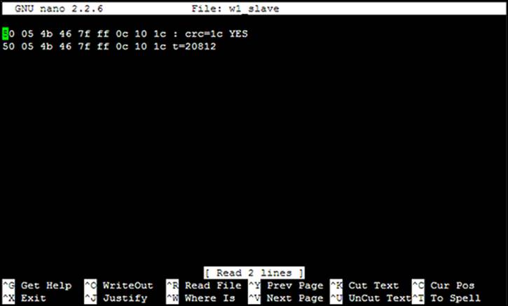
If you do see the new directory, navigate into it and view the contents of the w1_slave file, which will contain the temperature value. (Remember to replace my number with yours.)
cd /sys/bus/w1/devices/28-0000040be5b6
nano w1_slave
You will now see the contents of the w1_slave file, which contains the temperature data in Celsius. In my example (see Figure 13.10), the temperature is 20.812 degrees Celsius. Press Ctrl + X, followed by N, to exit.
Now that you have completed testing your circuit and have the sensor working, you will write some Python code to automate the preceding and print the temperature to the screen, as shown in Listing 13.2.
Figure 13-10: The temperature shown in the w1_slave file that was created by Modprobe.
Listing 13.2 Temperature Check
#!/usr/bin/env python
"""
Home Automation: temperature check
For the Raspberry Pi
"""
import subprocess
import time
def fileexists(filename):
try:
with open(filename): pass
except IOError:
return False
return True
def GetTemperature():
#set this variable to true if you want a Fahrenheit
#temperature
Fahrenheit = False
#These two lines call the modprobe application to get the
#temperature from the sensor
subprocess.call(['modprobe', 'w1-gpio'])
subprocess.call(['modprobe', 'w1-therm'])
#Open the file that you viewed earlier so that Python can
#see what is in it. Replace the serial number with
#your own number
filename = "/sys/bus/w1/devices/28-0000040be5b6/w1_slave"
if (fileexists(filename)):
tfile = open(filename)
else:
return 0
# Read the w1_slave file into memory
text = tfile.read()
# Close the file
tfile.close()
# You are interested in the second line so this code will
# put the second line into the secondline variable
secondline = text.split("\n")[1]
# You are interested in the 10th word on the second line
temperaturedata = secondline.split(" ")[9]
# You are interested in the number of the 10 word so
# you discard the first two letters "t=" and convert
# the remaining number $
temperature = float(temperaturedata[2:])
# Divide the value by 1000 to get the decimal in the
# right place
temperature = temperature / 1000
temp = float(temperature)
# Do the Farenheit conversion if required
if Fahrenheit:
temp=temp*1.8+32
temp = round(temp,2)
return(temp)
def main():
# This is the main routine of the program
print "The temperature is " + str(GetTemperature())
if __name__ == "__main__":
main()
Lastly, let’s create some code that will monitor the temperature and send an e-mail when the temperature exceeds a particular value. You will use the SendEmail function from the e-mail project (project 4 in this chapter). Using the program you created to print the temperature to the screen, replace the main routine with the code in Listing 13.3.
Listing 13.3 Temperature Alert
# This is the main routine of the program
tempind=False
while True:
temperature=GetTemperature()
if temperature > 25 and tempind==False:
#Use the SendEmail routine from the
#e-mail project
SendEmail("The temperature is "+ ![]()
str(temperature))
tempind=True;
else:
#This will ensure you only receive one e-mail
#once the temperature is above 25
#This variable is set back to false when the
#temperature is less than or equal to 25
tempind=False;
#Fetch the temperature every 10 seconds
time.sleep(10)
Project 4: How to Send an E-mail Alert
The sensors play an important role in monitoring your home but are not much use without having an action associated with them. An e-mail alert is a useful type of action as you can pack as much information as want into the body of the e-mail and send it to a smartphone. Other useful alerts (not detailed in this chapter) are a flashing LED, an LCD display and a buzzer or siren, which are all easily achievable tasks with a Raspberry Pi. Another useful tool for home automation, but also beyond the scope of this chapter, is a web page and a database. You can log sensor data to a database and design web pages to represent that data to you so that you can monitor your home.
What You Will Need
This project is all software based and can be used in conjunction with all the other projects in the chapter. All you will need is your Raspberry Pi, an editor and some Python code that I will provide.
Software
In order to send an e-mail from your Raspberry Pi, you need to send it from an e-mail server. You need to know your e-mail account details. There are three pieces of information you will need:
• The URL or IP address of the e-mail SMTP server
• Your username
• Your password
If you do not have these, you can use a Gmail or Yahoo! account. You will be creating a Python program called sendemail.py that will send a plain-text e-mail. The program accepts two command-line parameters. A command-line parameter is a value that you pass to the program. In this case you are passing the e-mail content as a parameter, as follows:
sudo python sendemail.py "Web cam motion detected"
sudo is a command telling the operating system to use super user rights when executing the command. Python tells the operating system to run some Python script. sendemail.py is the Python script you want to execute, and “Web cam motion detected” is the parameter you are passing into the sendemail.py program.
Create a file called sendemail.py that contains the code in Listing 13.4. Go through each line of code and ensure that you have filled in the details specified in the code comments.
Listing 13.4 Send E-mail
#!/usr/bin/env python
"""
Home Automation: send e-mail
For the Raspberry Pi
"""
import sys
import smtplib
from email.mime.text import MIMEText
import time
def SendEmail(MessageText):
#enter the e-mail account username between the quotes
smtp_user = ""
#enter the e-mail account password between the quotes
smtp_pass = ""
#sys.argv[1] is the 1st parameter that is passed to
#this program and it contains the text for the body
#of the e-mail
msg = MIMEText(MessageText)
#enter the target e-mail address between the quotes
msg['To'] = ""
#enter the e-mail account username between the quotes
msg['From'] = ""
#enter the message subject between the quotes
msg['Subject'] = ""
#enter the SMTP server URL or IP Address between the quotes
s = smtplib.SMTP("")
s.login(smtp_user,smtp_pass)
s.sendmail(msg['From'], msg['To'], msg.as_string())
s.quit()
def main():
SendEmail(sys.argv[1])
if __name__ == "__main__":
main()
Most e-mail servers use e-mail encryption, so there are two variations of the code in Listing 13.4, depending on which type of encryption is being used – transport layer security (TLS) or SMTP SSL encryption. You can find out what encryption is being used from your ISP, or through trial and error. If you have a Gmail or Yahoo! account, I have included details on how to send e-mails from their e-mail servers (providing you have an e-mail address with them).
Transport Layer Security
The code in Listing 13.5 will send an e-mail using TLS encryption.
Listing 13.5 Send E-mail Using TLS Encryption
#!/usr/bin/env python
"""
Home Automation: send e-mail using TLS encryption
For the Raspberry Pi
"""
import sys
import smtplib
from email.mime.text import MIMEText
def SendEmail(MessageText):
#enter the e-mail account username between the quotes
smtp_user = ""
#enter the e-mail account password between the quotes
smtp_pass = ""
#sys.argv[1] is the 1st parameter that is passed to
#this program and it contains the text for the body
#of the e-mail
msg = MIMEText(MessageText)
#enter the target e-mail address between the quotes
msg['To'] = ""
#enter the e-mail account username between the quotes
msg['From'] = ""
#enter the message subject between the quotes
msg['Subject'] = ""
#enter the SMTP server URL or IP Address between the quotes
s = smtplib.SMTP("",587)
s.ehlo()
s.starttls()
s.ehlo()
s.login(smtp_user,smtp_pass)
s.sendmail(msg['From'], msg['To'], msg.as_string())
s.quit()
def main():
SendEmail(sys.argv[1])
if __name__ == "__main__":
main()
SMTP SSL Encryption
The code in Listing 13.6 will send an e-mail using SMTP SSL encryption.
Listing 13.6 Send E-mail Using SSL
#!/usr/bin/env python
"""
Home Automation: send e-mail using SSL encryption
For the Raspberry Pi
"""
import sys
import smtplib
from email.mime.text import MIMEText
def SendEmail(MessageText):
#enter the e-mail account username between the quotes
smtp_user = ""
#enter the e-mail account password between the quotes
smtp_pass = ""
#sys.argv[1] is the 1st parameter that is passed to
#this program and it contains the text for the body
#of the e-mail
msg = MIMEText(MessageText)
#enter the target e-mail address between the quotes
msg['To'] = ""
#enter the e-mail account username between the quotes
msg['From'] = ""
#enter the message subject between the quotes
msg['Subject'] = ""
#enter the SMTP server URL or IP Address between the quotes
s = smtplib.SMTP_SSL("", 465)
s.login(smtp_user,smtp_pass)
s.sendmail(msg['From'], msg['To'], msg.as_string())
s.quit()
def main():
SendEmail (sys.argv[1])
if __name__ == "__main__":
main()
Sending E-mail Using a Gmail or Yahoo! Account
If you have a Gmail or Yahoo! account, you use your e-mail address as the e-mail account and the e-mail password as the e-mail account password. Gmail uses SSL, so edit the SSL encryption code (in Listing 13.6) with the following SMTP server details:
smtp.gmail.com
Yahoo! uses TLS, so edit the TLS encryption code (in Listing 13.5) with the following as the SMTP server details:
smtp.mail.yahoo.com
How to Attach a File to an E-mail
In the section “Project 2: How to Monitor Your Home with a Webcam”, a command was introduced that enabled you to send a photograph attachment when the webcam detected motion. The code in Listing 13.7 will allow you to do it. You will build on the sendemail.py program you created earlier (in Listing 13.4) by adding a new parameter to pass the filename of the photo you want to attach to the e-mail. Remember to update this program with the code depending on the type of encryption you require as explained earlier. In this example I’ve assumed SSL encryption. The emailphoto.py program accepts two parameters: the first for the message text and the second for the filename of the photo you want to send. For example, you will run this program using the following command:
sudo python sendemail.py 'Webcam motion detected', ![]()
'/home/photo.jpg'
Listing 13.7 is the code for emailphoto.py that will attach a photograph to the e-mail. I have created a function called emailphoto because it is used in other programs within this chapter.
Listing 13.7 Send E-mail with a Photo Attachment
#!/usr/bin/env python
"""
Home Automation: sends an e-mail with a photograph attachment
For the Raspberry Pi
"""
import sys
import smtplib
from email.mime.text import MIMEText
from email.mime.application import MIMEApplication
from email.mime.multipart import MIMEMultipart
def emailphoto(msgtext, afilename):
#enter the e-mail account username between the quotes
smtp_user = ""
#enter the e-mail account password between the quotes
smtp_pass = ""
msg = MIMEMultipart()
#enter the target e-mail address between the quotes
msg['To'] = ""
#enter the e-mail account username between the quotes
msg['From'] = ""
#enter the message subject between the quotes
msg['Subject'] = ""
#That is what you see if don't have an e-mail reader:
msg.preamble = 'Multipart message.\n'
#sys.argv[1] is the 1st parameter that is passed to this
#and it contains the text for the body of the e-mail
part = MIMEText(msgtext)
msg.attach(part)
#The next 3 lines attach the photo using the filename
#passed in as the second parameter to this program
part = MIMEApplication(open(afilename,"rb").read())
part.add_header('Content-Disposition', 'attachment', ![]() filename=afilename)
filename=afilename)
msg.attach(part)
#enter the SMTP server URL or IP Address between the quotes
s = smtplib.SMTP_SSL("", 465)
s.login(smtp_user,smtp_pass)
s.sendmail(msg['From'], msg['To'], msg.as_string())
s.quit()
def main():
emailphoto(sys.argv[1], sys.argv[2])
if __name__ == "__main__":
main()
Project 5: How to Send an E-mail Using a Wireless Remote
In this project you will use a wireless remote to send a signal to the Raspberry Pi to check the status of the sensors that you have built in the other projects in this chapter and then send yourself an e-mail report of all the sensors in the house. This is an example of the control category of home automation. The e-mail will contain the temperature, status of door switches and motion sensors and a picture of the last motion detected by the webcam. Other typical uses of a wireless remote in home automation are switching lights on and off (particularly external lights), switching or sounding an alarm system, opening and closing a garage door and automating blinds and curtains. As you get access to more home-automation sensors and controllers within your home you can use what you learn in this chapter to add remote control to those devices. Table 13.6 shows what you need.
Table 13-6 What You Will Need
|
QTY |
Item |
Description |
|
1 |
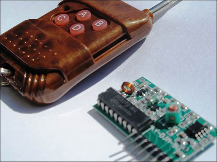
Wireless remote kit |
This is shown later in Figure 13.11. There are a number of kits available on the market that consist of a key-fob remote and a receiver. The receivers are usually 5V-10V and have four digital outputs. The key fobs vary from one button to four buttons. There are different kinds of receivers (momentary, toggle and latch). You are using a momentary receiver here (explained further later). |
|
1 |
5V power supply |
Although this is not mandatory because the Raspberry Pi does have a 5V power supply, I recommend a separate power supply for the receiver. It is best to not overload the Raspberry Pi, and I have found that the current required by this RF receiver exceeds that of the Raspberry Pi, which affects the distance you can get between the key fob and the receiver. An old cell phone power supply should work (5V 700mA). Be sure to check the voltage and current of both input and output in the data sheet of the receiver you purchase. The output signal voltage should be 5V. |
|
1 |
PN2222A transistor |
Switching NPN bipolar transistor 40V/.6A. |
|
1 |
10kΩ resistor |
Brown, black, red, gold. |
|
2 |
1kΩ resistors |
Brown, black, orange, gold. |
|
1 |
Solderless breadboard |
A prototyping board for which parts and wires can be connected by clipping them into the board. It is used for prototyping electronics without having to solder parts together. |
|
3, 4 |
Jumper wires |
Male to male for breadboard connections, male to female for connecting the breadboard to the GPIO pins. Jumper wires usually come in packs of various quantities, colours and sizes. Although you need only 7 for this project, having 20 to 30 of each should see you through most projects. Any size will do for this project, but shorter male to male (10 cm) and longer male to female (20 cm) are best. |
Construction
Radio frequency circuits are complex and not worth building yourself when they are readily available prebuilt for a minimal cost (as shown in Figure 13.11). As discussed earlier, there are different types of radio frequency circuits available on the market (momentary, latch and toggle) that all work slightly differently. A momentary receiver’s digital output will remain on as long as the key-fob button is pressed. The latch receiver will ensure that only one output pin is on at any one time. For example, if you press button A, digital output A will go on. If you press B, A will go off, and B will go on – and so on. A latching receiver digital output goes on when a button is pressed in and out, and off when the same button is pressed in and out. In this project you will use a momentary receiver, but you can use any type and adjust the Python code to suit the type of the receiver.
Figure 13-11: A wireless remote kit.
This is the first time in this chapter you have used a transistor. Although transistors have many uses, one of the lesser-known uses is the capability of a bipolar transistor to switch things off and on. With the flat surface facing you, the PN2222 transistor has three pins from left to right: the emitter, the base and the collector. When voltage is applied to the base the transistor allows the current to flow through the emitter (source) to the collector (drain). You will construct a switch similar to what you did in the section “Project 1: How to Create a Motion Sensor and Door Switch”, but instead of a door switch you will use the transistor to switch the Raspberry Pi GPIO when the wireless receiver receives a signal. The reason you do not connect the receiver directly to the GPIO pin is that it has an external 5V supply and will damage the GPIO pin, which has a 3V maximum.
![]()
Be extremely careful when working with circuits (especially 5V) that connect to the GPIO pins as they are not protected and you can very easily cause permanent damage to your Raspberry Pi. Double-check the wiring before powering on the Raspberry Pi and the external power supply.
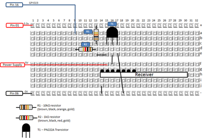
Figure 13.12 is the circuit diagram, and Figure 13.13 is the breadboard layout diagram. Depending on which key-fob receiver you have, you may need to alter the receiver pin connections. In this example pin 1 is ground, pin 2 is 5V and pin 3 is data. The other pins are usually allocated to additional key-fob buttons or a receiver aerial. Before you buy a kit refer to the data sheet of the receiver to check the pin configuration and check the output voltage.
Figure 13-12: A circuit diagram for the wireless receiver connected to a Raspberry Pi.
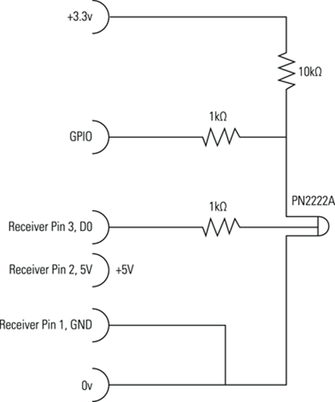
Figure 13-13: A breadboard layout for the wireless receiver connected to a Raspberry Pi.
Software
The program in Listing 13.8 will loop and wait until the key-fob button is pressed. When it is pressed it will poll the door switch, motion detector and temperature sensor and get the latest picture created by the webcam. You then send an e-mail using the sendemail.py program you created inListing 13.4. The status of all the sensors is in the body of the text, and the latest webcam photo is attached to the e-mail. Every time you press the key fob, an e-mail will be sent.
Listing 13.8 Send E-mail Using a Wireless Remote
#!/usr/bin/env python
"""
Home Automation: send e-mail using wireless remote
For the Raspberry Pi
"""
import os, glob, time, operator
import RPi.GPIO as GPIO
import time
import sys
import smtplib
from email.mime.text import MIMEText
from email.mime.application import MIMEApplication
from email.mime.multipart import MIMEMultipart
from time import gmtime, strftime
def get_latest_photo(files):
lt = operator.lt
if not files:
return None
now = time.time()
latest = files[0], now - os.path.getctime(files[0])
for f in files[1:]:
age = now - os.path.getctime(f)
if lt(age, latest[1]):
latest = f, age
return latest[0]
def emailphoto(msgtext, afilename):
#enter the e-mail account username between the quotes
smtp_user = ""
#enter the e-mail account password between the quotes
smtp_pass = ""
msg = MIMEMultipart()
#enter the target e-mail address between the quotes
msg['To'] = ""
#enter the e-mail account username between the quotes
msg['From'] = ""
#enter the message subject between the quotes
msg['Subject'] = ""
# That is what u see if don't have an e-mail reader:
msg.preamble = 'Multipart message.\n'
#sys.argv[1] is the 1st parameter that is passed to this
#and it contains the text for the body of the e-mail
part = MIMEText(msgtext)
msg.attach(part)
#The next 3 lines attach the photo using the filename
#passed in as the second parameter to this program
part = MIMEApplication(open(afilename,"rb").read())
part.add_header('Content-Disposition', 'attachment',![]() filename=afilename)
filename=afilename)
msg.attach(part)
#enter the SMTP server URL or IP Address between the quotes
s = smtplib.SMTP_SSL("", 465)
s.login(smtp_user,smtp_pass)
s.sendmail(msg['From'], msg['To'], msg.as_string())
s.quit()
def sendreport():
msgtext = "This is a sensor status report for " +![]() strftime("%Y-%m-%d %H:%M:%S", gmtime()) + "\n"
strftime("%Y-%m-%d %H:%M:%S", gmtime()) + "\n"
if GPIO.input(13) == True:
msgtext = msgtext + "Status of door switch is :![]() Door open\n"
Door open\n"
else:
msgtext = msgtext + "Status of door switch is :![]() Door closed\n"
Door closed\n"
if GPIO.input(15) == True:
msgtext = msgtext + "Status of motion detector ![]() is : No motion\n"
is : No motion\n"
else:
msgtext = msgtext + "Status of motion detector ![]() is : Motion detected\n"
is : Motion detected\n"
# Use the GetTemperature routine we
# created in the temperature project
Temperature = GetTemperature()
msgtext = msgtext + "The temperature is :![]() "+str(Temperature)+"\n"
"+str(Temperature)+"\n"
# Change this to your path where the
# web cam pictures are stored.
# *.jpg means all JPEG files
photopath = "/home/*.jpg"
files = glob.glob(photopath)
latestphoto = get_latest_photo(files)
msgtext = msgtext + 'Latest photo:' + latestphoto + "![]() is attached to this e-mail\n";
is attached to this e-mail\n";
# Send e-mail using the emailphoto()
# function we created in the e-mail
# project
emailphoto(msgtext, latestphoto)
print "Report has been sent."
#main program
def main():
GPIO.setmode(GPIO.BOARD)
GPIO.setup(16, GPIO.IN) #RF Remote Receiver
GPIO.setup(13, GPIO.IN) #Door switch
GPIO.setup(15, GPIO.IN) #Motion sensor
rfkey = False
while True:
if GPIO.input(16) == False: #RF key-fob key pressed
if rfkey == False:
rfkey = True
sendreport()
else:
rfkey = False
time.sleep(.3)
if __name__ == "__main__":
main()
Over to You
Over the course of this chapter, you learned how to interface with sensors that give you information about your home (movement, temperature, video and pictures). You acted on this information by creating e-mail alerts, and in the last project I introduced an element of remote control. You now have the building blocks for your next home automation project. Here are some ideas:
• Place a door switch on a dog flap and send an e-mail every time your dog enters or leaves the house.
• Detect when your garage door has been open for more than 10 minutes.
• Switch off a light when no motion is detected for a period of time.
These projects, plus many more, are now well within your reach.
All materials on the site are licensed Creative Commons Attribution-Sharealike 3.0 Unported CC BY-SA 3.0 & GNU Free Documentation License (GFDL)
If you are the copyright holder of any material contained on our site and intend to remove it, please contact our site administrator for approval.
© 2016-2026 All site design rights belong to S.Y.A.