Raspberry Pi Projects (2014)
Part III. Hardware Projects
Chapter 14. Computer-Controlled Slot Car Racingby Mike Cook
In This Chapter
• Learn how to use your Raspberry Pi to enable and disable a slot car set
• See how to make your own illuminated joystick pad
• Discover how to use an external text file as a question bank
• Understand the interactions between the software and hardware
This project is a rather different twist on the multiple-choice quiz theme. Not only does it have a novel way of inputting answers, but it also has a rather novel way of keeping the score.
The idea is that you are going to hack into a slot car game and allow the Raspberry Pi to control when the game can be played. Then players can drive their cars for three seconds at a time, if they are the first to answer a question correctly. If they get the question wrong, their opponent gets the time. The game continues until one player crosses the finishing line after completing a set number of laps. The questions come from a plain text file and can be added to, or the subject of them changed. They are multiple-choice questions with four possible answers, and players indicate their answer by moving a special joystick button. The successful player’s joystick button will light up green, whereas the other player’s button will light up red.
Obtaining a Slot Car Racer
So how are you going to implement this game? First you need a slot car racing game. These come in all sorts of shapes and sizes, from sleek Formula One racing cars to heavy trucks and even grannies on Zimmer frames. In essence they are very similar: It’s a race between two players. Mostly they are set up so that if you go too fast at the corners, the vehicle will come off the track, so it is not just a matter of running the cars at top speed all the time. Normally the track is some form of figure eight, so the track length can be made the same for both players. Sometimes the two vehicles cross at the same level, giving opportunities for crashes, and other times the tracks go over and under each other. Although there are very expensive racing games, some can be had cheaply in thrift shops or second-hand stores.
Hacking Your Slot Car Racer
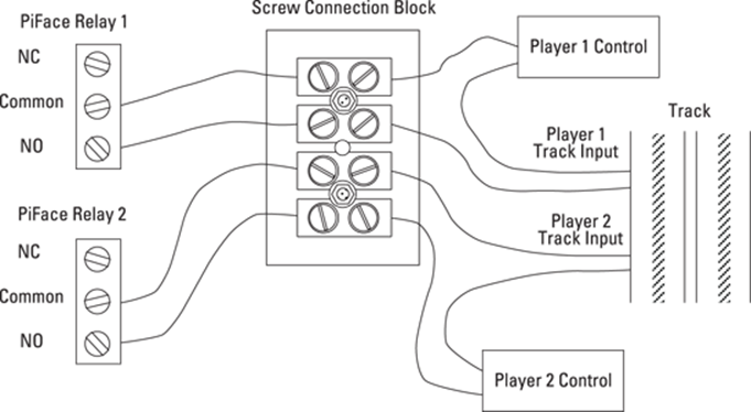
You need to hack into your slot car racer, and, as there are lots of different types of them, I can’t be too prescriptive about what you need to do. However, from the electrical point of view, it is basically all the same. What you are going to do is to wire a PiFace relay in series with each hand controller. This will involve cutting one of the two wires coming from the controller, and connecting each end of your cut wire into the NO and common relay connections. NO stands for normally open – this connection is only connected to the common line when the relay is energised; when the relay is not energised, that is the normal state – no electrical connection is made. Figure 14.1 shows how you can do this using a screw connection block. These are the type you use for electrical wiring around the house. They come in various sizes, and the size you want is the smallest, which is often marked something like 3 Amps. A sharp hobby knife can slice the two wires apart, and then you can cut one of them; it doesn’t matter which one. You should cut back the insulation and then, following the diagram, attach each end to two of the connector blocks. Take the other end and run wires off to the PiFace board. Do the same for the other controller. When you want to play with your slot car game normally you simply replace the long wires trailing back to the PiFace board with a simple link. Do this close to the track connections so that you have the maximum length of wire on the hand controllers.
Figure 14-1: Hacking into your slot car racing game.
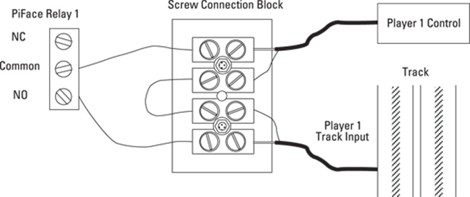
Sometimes the wires coming from the hand controller are all bundled into one cable, so it is impossible to cut just one wire. If this is the case, you will have to cut both of them and join the other wire back up again. This sort of thing is shown in Figure 14.2. In this case the wire consists of an inner conductor and an outer braided wire sheath. Strip back the outer sheath and make sure that no thin strands of wire are shorting out to the other wire. Use insulation tape or heat shrink sleeving to insulate the sheath. Then wire it up as shown in Figure 14.2. Note that this diagram is for one controller; you will have to duplicate this for the other player’s controller.
Figure 14-2: Hacking into your slot car racing game if you can’t cut just a single wire.
Testing Your Slot Car Racer Hack
Now you need to test the slot car hack. Power up your slot car racing game as normal and run the program in Listing 14.1.
Listing 14.1 Slot Car Racer Hack Test
#!/usr/bin/env python
"""
Slot Racer Hack tester on the PiFace board
"""
import piface.pfio as pfio # piface library
pfio.init() # initialise pfio
def main():
lastInput =0
print "Slot Racer Hack test press the two input ![]()
switches"
print "on the PiFace board to change who is racing"
print "Ctrl - C to quit"
while True :
buttons = pfio.read_input()
if (buttons & 1) ==1 and buttons != lastInput:
print "player 1 racing"
pfio.write_output(0x01)
if (buttons & 2) ==2 and buttons != lastInput:
print "player 2 racing"
pfio.write_output(0x02)
lastInput = buttons
if __name__ == '__main__':
main()
You will see it is a very simple program that just energised each of the relays depending on if you press one of two buttons on the end of the PiFace board. A message is printed to say which player is racing each time it changes. Make sure that the players are the right way around and that you can play when the console message says you can. If you find the control is the wrong way around – that is, when it says you can play you can’t and when it says you can’t you can – then you may have mixed up the NO and the NC relay connections. NC stands for normally closed – there is a connection between the common line and this one when the relay is not energised. If you don’t hear the relay clicking at all but do see the two lower LEDs come on and off, then check that the links JP5 and JP6 are made.
Getting the Player Input
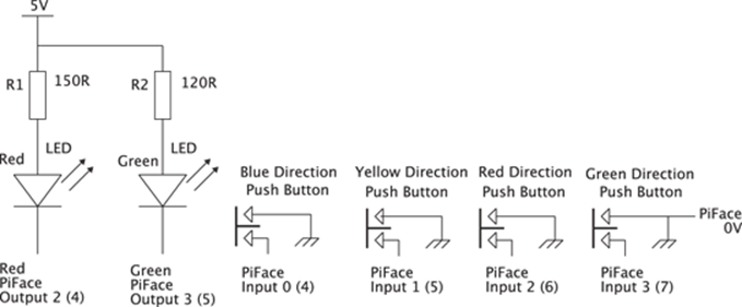
Next you need to find a way to input the players’ answers. You could just arrange a row of four switches for each player along with red and green LEDs. In fact the schematic in Figure 14.3 can be implemented in exactly that way. However, at this stage in the game you can be a lot more adventurous than that, so I am going to show you how to make an illuminated switch joystick using that same schematic. Not only is this useful for this project, but you also can use the joystick on other projects in this book, replacing a keyboard input. In Chapter 8, “Colour Snap”, the colour snap project shows you how useful half table tennis balls are at acting as a light diffuser. Well, now they are back, and this time they are even more useful. You are going to mount four tactile button switches on a board, and, in each of the corners, have foam pads that are slightly taller than the switches. Then, if you put the board switch side down, you can click each switch in turn by simply pushing the board in that direction. The feel of the switch is down to the rigidity of the foam pads you use. On the track side of the board, you mount a red/green LED and cover the board in a half table tennis ball. Let’s see how to do that in detail.
Figure 14-3: A schematic of the joystick button controller.
![]()
The LED needs to be a bright one: Look for one with at least 60 mcd on the red, and 40 mcd on the green at 20mA – brighter if you can get it; otherwise the switch could look a bit washed out. I found 90 mcd red and 45 mcd green, which looked good.
Making the Joystick Buttons
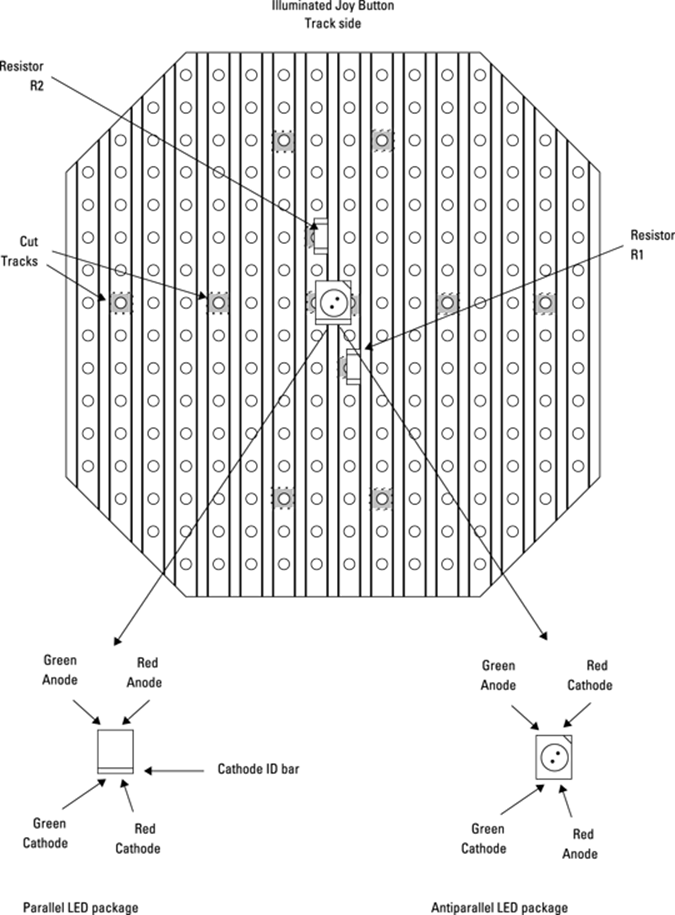
Take a small piece of strip board 17 holes long, and 16 strips wide. I like to take the corners off the board to give it an octagonal shape, just to make it look neater and ensure that the corners don’t snag on the base. Cut the tracks on the back of the board where the dark marks are on Figure 14.4. Make sure that you count the tracks and holes carefully. Then solder a surface mount red/green LED at the centre of the board, as shown between the two tracks and two track cuts. Make sure that the orientation mark on the LED is correctly aligned. There are two types of surface mount LEDs that you can get. One has the LEDs pinned out to the package in parallel; that is, the two anodes are on one side and the two cathodes on the other. This is sometimes known as a parallel LED pinout. The other way is known as antiparallel, where one anode and one cathode are together at each end; these normally have a bar or some other marker, often green, denoting the cathode. Make sure that you know which you are using. I have designed the board so that the tracks you need to cut are the same for both versions. However, the links on the component side are different for each LED type. When the LED is in place solder the two surface mount resistors as shown between the cut marks. If you haven’t got surface mount resistors, then one-eighth watt, or one-tenth watt, resistors should be small enough to mount on the tracks.
Figure 14-4: The track side of the joystick button controller board.
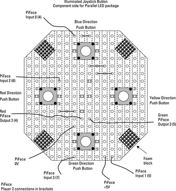
Now turn the board over and mount and solder the four tack buttons. This is shown in Figure 14.5 for an antiparallel LED package and Figure 14.6 for a parallel LED package. The differences are minor but important. The switches’ contacts should be either side of the cut tracks as you insert them through the board. Note that in these figures, the copper strips are shown as hidden detail dotted lines, and the cut tracks are also shown as shaded. This is for ease of orientation, although you won’t actually see this when you look at the board for real. The solid lines are tinned copper links; these can be the scrap from cutting the legs of components or simply stripped-back solid core wire. The foam pads can be glued on using impact adhesive; you can cut them out from some packing material. Finally, a strip of 8-way ribbon cable is soldered to the board to make the connections, and spots of hot melt glue make sure that the wires do not foul the switches or pads. A photograph of this is shown in Figure 14.7; note that it is a photograph of the antiparallel LED version of the joystick so it corresponds to Figure 14.5. At this point you should test the board as described later in the subsection “Joystick Testing”. In that way you can correct any mistakes before too much gluing is done. However, I will first continue the building narrative as the finished article needs testing as well.
Figure 14-5: The joystick button controller components for antiparallel LED.
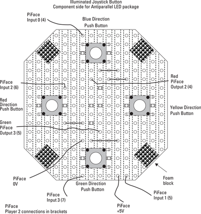
Figure 14-6: The joystick button controller components for parallel LED.
Boxing It Up
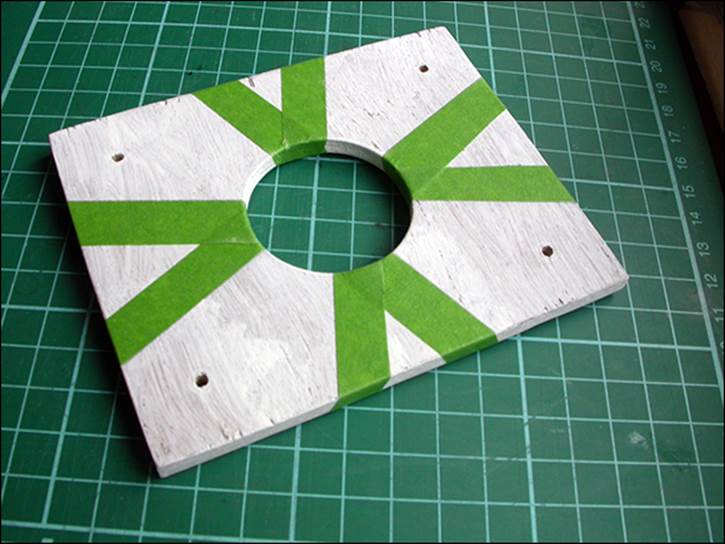
Now for the box to put it in. I used the plywood layer technique described in Chapter 8 to make a box 116 mm (4 5/8") by 92 mm (3 3/4"), but the dimensions are not too critical. I made the sides from 12 mm by 5 mm strip pine, and I fastened together the top and bottom with 10 mm M3 spacers or tapped pillars. The holes in the bottom sheet were countersunk, and in the centre of the top I used a saw drill to make a 40 mm hole. I gave it a coat of primer and then painted. Each radial direction was painted a colour to match the software in the game – blue up, green down, red right and yellow left. The spaces in between were painted grey. Figure 14.8 shows the box taped up with painter’s tape, ready to receive the grey paint layer. Remove the tape while the paint is still wet, and then when it has dried mask off the grey areas and paint in the colours.
Figure 14-7: A photograph of the joystick button controller components for antiparallel LED.
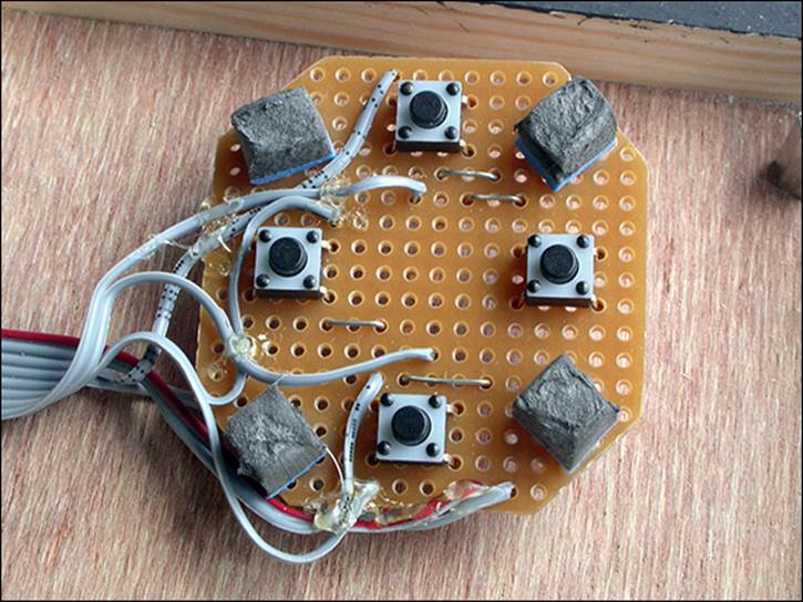
Figure 14-8: The joystick button box masked up before painting.
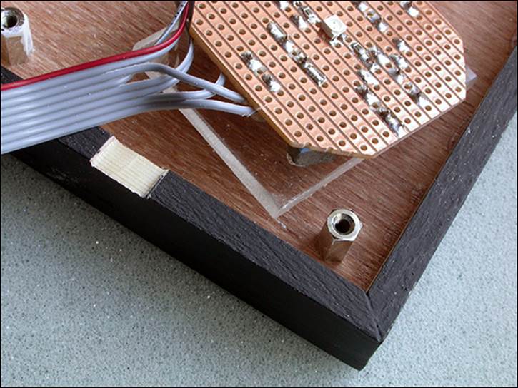
To make sure that the top of the board is flush with the top of the hole, I mounted the board on a piece of 4 mm acrylic by gluing the foam pads with impact adhesive. Figure 14.9 shows a side view of this arrangement; note how the buttons are not in direct contact with the acrylic. I filed a slot in the side of the box to allow the ribbon cable to come through, as shown in Figure 14.10.
Figure 14-9: A side view of the joystick button controller button switches.
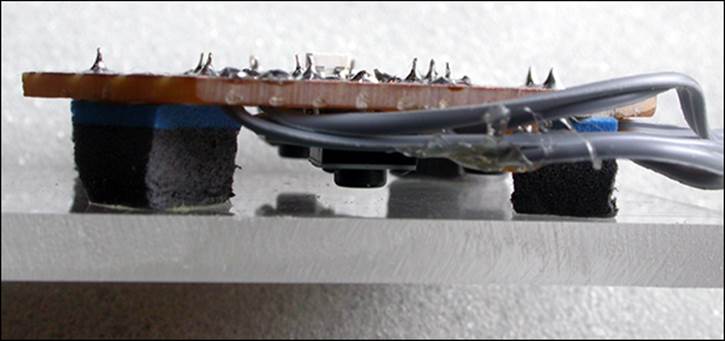
Figure 14-10: The joystick button controller slot for connecting ribbon cable.
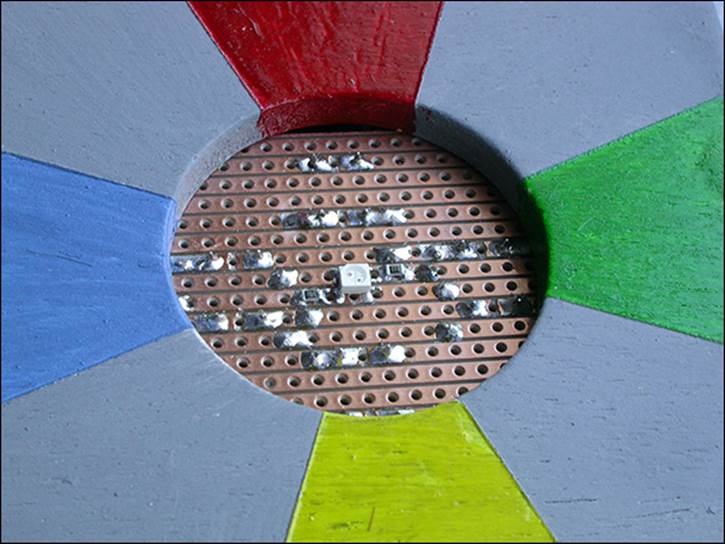
Next is the most important part: You have to glue the acrylic in the correct place in the board. Make sure that the copper strips are parallel with the box edge and that the LED is in the centre of the hole when the lid is on. Then hold the board through the hole and remove the lid of the box. Add some hot melt glue to the corners of the acrylic sheet without moving it. What makes this difficult is the wire that is wanting to twist the orientation of the board. Bend the wire to your will. Figure 14.11 shows the board with the hole correctly aligned.
Figure 14-11: The joystick button controller aligned under the central hole.
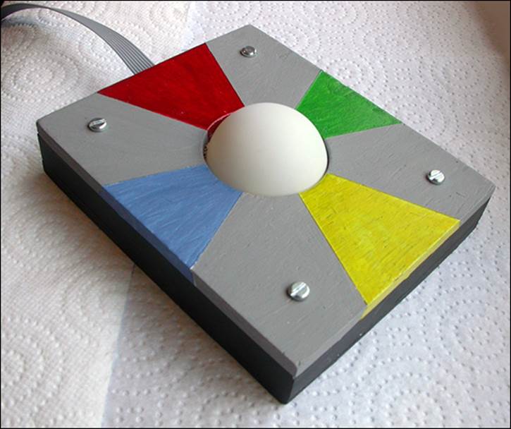
Finally, fix the ribbon cable to the slot in the top side with a bit more hot melt glue. When it has finally tested correctly you can glue the half table tennis ball by dropping it through the hole as shown in Figure 14.12. When this has dried remove the lid and add a fillet of glue neatly round the whole of the ball. Just remember you need two of these joysticks; the connections to the PiFace board for the second player’s joystick button are shown in Figures 14-5 and 14-6 in brackets.
Joystick Testing
Just as with the slot car hack, you need to test your joystick buttons using a simple program before you try anything fancy with it. The test program is shown in Listing 14.2.
Figure 14-12: The complete joystick button controller.
Listing 14.2 Testing the Joystick Buttons
#!/usr/bin/env python
"""
Joystick button tester on the PiFace board
"""
import piface.pfio as pfio # piface library
pfio.init() # initialise pfio
positions = ["nothing", "north (blue)", "west (yellow)", ![]()
"north west", "east (red)","north east","east & west??", ![]()
"big north", "south (green)", "north & south??", "south ![]()
west", "big west", "south east", "big east", "big south", ![]()
"all on"]
def main():
lastInput =0
print "Joystick test press the joystick button"
print "Ctrl - C to quit"
while True :
buttons = pfio.read_input()
if buttons != lastInput and buttons != 0:
print "bits are",hex(buttons)
print "player 1",positions[buttons & 0xf]
print "player 2",positions[buttons >> 4]
print " "
leds = (buttons & 0xC) | ((buttons >> 2) & 0x30)
pfio.write_output(leds)
lastInput = buttons
if __name__ == '__main__':
main()
When you first run this you will get the introductory message. Then any press on the joystick will print out the bit pattern, in hex, read from the PiFace inputs, and followed by a message telling you the state of each player’s buttons. These are displayed as the points of the compass with the colours used in the slot car racing game in brackets. If you press in the east or south direction, the red or green LED comes on and stays on until there is a change in either button.
The program is quite simple. First the inputs are polled as fast as possible, and then an if statement is used to see if the input has changed since the last time it was looked at and also that the input has a nonzero value. This ensures that you get only one message per key press and you don’t get a message when the key is released. The bit pattern is then printed in hex, and the joystick button positions for each player are printed out. These position messages are held in a list called positions, and there is an entry for each of the possible 16 different combinations. Player 1 has the four least significant bits of the input, and a simple bitwise AND operation just leaves player 1’s input bits to use to look up what to print. For player 2 the top four bits in the input are shifted down to the bottom four bits so that the same lookup table list can be used. Finally a bit pattern is calculated to see what LEDs to light. This takes bits 6 and 7 and shifts them into the position of bits 4 and 5. Then this is merged with bits 2 and 3 to give the output you need.
Notice that there are some positions with question marks; it is quite hard for example to press both east and west without pressing either north or south – it is easier without the table tennis ball attached, but that is not something you want to require when using the joystick button in an application. These intermediate positions have to be included in the positions list because you have to cater for all combinations, physically possible or not. There are also positions such as a “big south”, which is one where east, west and south are all being pressed at one time. One thing you might notice when testing some positions is that you get two messages such as one saying south followed by another saying south west. This is because it is almost impossible to press two buttons simultaneously; one goes down first followed by the other and so there is a message for each. This is something to consider when using the joysticks in your own game.
The Software
After you have all the hardware prepared you are ready to put together the software support for this project. This consists of two files, a question bank and a screen background logo. You need at least one file containing the questions and answers; later on you might extend this to more question banks, but for a start let’s look at just one file. You need a simple text file, just like those you can create with Leafpad. Place one question per line, with the question first, followed by the correct answer, and followed by three incorrect answers. Separate all the sections with commas including the last answer. You will see that there is a space between the end of the last word and the comma, which allows the spacing in the box to look right. Listing 14.3 is a sample of the file format with just a few questions on the subject of IT. You should save it under the name questions.txt.
Listing 14.3 Sample Questions
How many bits in a byte? , 8 , 10 , 4 , 16 ,
Which company did Bill Gates start? , Microsoft , Apple , Google , Facebook ,
What is the largest? , Terabyte , Gigabyte , Megabyte , Kilobyte ,
Which country owns the WWW suffix .de? , Germany , France , Denmark , Dominica ,
What is the command to list files in Windows? , dir , ls , cat , files ,
What does UNIX stand for? , Nothing , UNIt eXchange , The creators name , UNidentified Integrated eXchange ,
Which of the following is an operating system? , Linux , Bantex , Hopex , Bandx ,
What computer language uses the tags <body> and <meta/>? , HTML , Java , Python , Scratch ,
What does DBMS stand for? , Database management system , Database migration statistics , Database management statistics , Database migration statistics ,
Who invented the web? , Tim Berners-Lee , Alan Turing , Clive Sinclair , Stephen Hawking ,
What was the forerunner to the Internet called? , ARPANET , SKYNET , OUTERNET , FASTNET ,
What does LAN stand for? , Local Area Network , Legitimate Access Network , Local Access Network , Legitimate Area Network ,
What was the first stored-program computer called? , The Baby , The Infant , The Newborn , The Tiny ,
What is another name for a CPU? , Processor , Disk drive , Memory , Thinker ,
What is Magnetic Ink Character Recognition often used on? , Cheques , Bar codes , QRC , Laundry ,
Which of these is a mobile operating system? , Android , Windows Vista , OS X , RISCOS ,
What are the tiny points of colour on your monitor called? , Pixels , Pacsels , Points , Pica ,
What does WYSIWYG stand for? , What you see is what you get , What you see is where you go , What you see is what you give , What you seek is where you go ,
Where the question overruns a single line in this listing, you should type it in all on one line when you create the file.
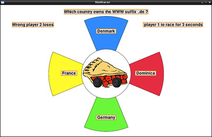
The other thing you need to prepare is the background screen logo. I made mine in Gimp, but you can use any graphics drawing program. The image size needs to be 555 pixels by 540 pixels and should mirror the joystick buttons in some way. Figure 14.13 shows the program running, and you can see the background logo underneath the multiple-choice boxes. The file should be called racingLogo.png and be in the same directory as the game code and the questions file. However, the program will cope without its being present, but it’s not so colourful.
Figure 14-13: The game in progress.
The Game
Now you can get down to the game itself, which is shown in Listing 14.4.
Listing 14.4 The Slot Car Racing Game
#!/usr/bin/env python
"""
Slot Racer on the PiFace board
"""
import time # for delays
import piface.pfio as pfio # piface library
import random
import os, pygame, sys
pfio.init() # initialise pfio
pygame.init() # initialise graphics interface
os.environ['SDL_VIDEO_WINDOW_POS'] = 'center'
pygame.display.set_caption("SlotRacer")
screen = pygame.display.set_mode([980,610],0,32)
background = pygame.Surface((980,610))
piSurface = pygame.Surface((555,540))
# define the colours to use for the user interface
cBackground =(255,255,255)
cLEDon = (255,0,0)
cLEDoff = (128,128,128)
cOutline = (255,128,0)
cText = (0,0,0)
cTextBack = (220,220,220)
altcText = (255,255,255)
altcTextBack = (180,180,180)
cStepBlock = (0,255,255)
# cope with not having the picture of the racing pi
try:
piPicture = ![]()
pygame.image.load("racingLogo.png").convert_alpha()
piSurface.blit(piPicture,[0,0])
except:
piSurface.fill((220,220,220)) # make just a grey area
# Set up questions
qfile = open("questions.txt","r")
questions = list()
numberOfQuestions = 0
for line in qfile.readlines():
questions.append(line)
numberOfQuestions +=1
qfile.close()
random.shuffle(questions)
placeX = [490,490,355,625,490, 150, 800]
placeY = [ 20, 110, 305, 305, 510, 80 ,80]
aPos = [-1,-1,-1,-1]
single = [0, 1, 2, 0, 3, 0, 0, 0, 4, 0, 0, 0, 0, 0, 0, 0]
background.fill(cBackground) # make background colour
font = pygame.font.Font(None, 28)
seq = [ 1 << (temp & 0x7) for temp in range (0,32)]
# initial sequence
timeInc = 0.3
stepInt = True # getting the step signal from inside the Pi
step = 0 # start point in sequence
nextTime = time.time()
answer = "answer"
answerPos = -1
def main():
ask =0
while True :
while pfio.read_input() != 0:
checkForEvent() # wait until switch is released
setupScreen(ask)
checkInput()
ask += 1
if ask >= numberOfQuestions :
ask = 0
random.shuffle(questions)
def checkInput():
buttonsInput = 0
while buttonsInput == 0:
buttonsInput = pfio.read_input()
checkForEvent()
if buttonsInput >= 0x10 :
first = " player 2 "
second = " player 1 "
buttonsInput = buttonsInput >> 4
bits = 0x26
else:
first = " player 1 "
second = " player 2 "
bits = 0x19
#print hex(buttonsInput), single[buttonsInput] , answerPos
if single[buttonsInput] == answerPos:
drawWords("Correct"+first+"wins", 5, False)
drawWords(first+"to race for 3 seconds", 6, False)
pfio.write_output(bits)
else:
drawWords("Wrong"+first+"loses", 5, False)
drawWords(second+"to race for 3 seconds", 6, False)
pfio.write_output(bits ^ 0x3f)
correct()
pfio.write_output(0)
correct() # keep on flashing for a bit
def scramble():
global aPos
aPos = [-1,-1,-1,-1]
for p in range(0,4):
match = True
while match:
match = False
candidate = random.randint(1,4)
for i in range(0,4):
if aPos[i] == candidate:
match = True
aPos[p] = candidate
def setupScreen(question) : # initialise the screen
global answer, answerPos
screen.blit(background,[0,0]) # set background colour
screen.blit(piSurface,[210,50])
pygame.display.update()
time.sleep(2.0) # delay while the players settle down
q = questions[question].split(",")
scramble()
drawWords(q[0],0, False)
drawWords(q[1],aPos[0], False)
drawWords(q[2],aPos[1], False)
drawWords(q[3],aPos[2], False)
drawWords(q[4],aPos[3], False)
pygame.display.update()
answer = q[1]
answerPos = aPos[0]
def drawWords(words,pos,inv) :
if inv :
text = font.render(words, True, altcText, ![]()
altcTextBack )
else :
text = font.render(words, True, cText, cTextBack )
textRect = text.get_rect()
if pos == 2 :
textRect.right = placeX[2]
elif pos == 3:
textRect.left = placeX[3]
else:
textRect.centerx = placeX[pos]
textRect.top = placeY[pos]
pygame.draw.rect(screen,cTextBack, textRect, 0)
screen.blit(text, textRect)
pygame.draw.rect(screen,cOutline, textRect, 2)
def correct() :
nextTime = 0
for flash in range(0,10) :
while time.time() < nextTime :
pass
if flash & 1:
drawWords(answer,answerPos, False)
else :
drawWords(answer,answerPos, True)
pygame.display.update()
nextTime = time.time() + 0.3
def terminate(): # close down the program
print ("Closing down please wait")
pfio.deinit() # close the pfio
pygame.quit() # close pygame
sys.exit()
# see if we need to quit or look at the mouse
def checkForEvent():
event = pygame.event.poll()
if event.type == pygame.QUIT :
terminate()
elif event.type == pygame.MOUSEBUTTONDOWN :
pass
#print pygame.mouse.get_pos()
elif event.type == pygame.KEYDOWN and event.key == ![]()
pygame.K_ESCAPE :
terminate()
if __name__ == '__main__':
main()
The program starts with a lot of initialisation for screens, colours and variables. Then the question file is opened, and all the lines are read into a list, called, appropriately enough, questions. The lines are counted, and then the order of the questions is shuffled so it is different every time. After that are some variables that define where things are going to appear on the screen: the question, the four answers, the player who is correct message and the player who gets to race message. It is convenient having them all in one place for when you want to tinker with the screen layout. What’s left is a useful development tool in this code, one that prints out the position of the pointer when you click the mouse. This is useful for knowing where to place things. If you want to use it, just remove the # in front of the print .mouse.get_pos instruction. Finally, the list calledsingle has the conversion lookup table required to translate between the button press, and the answer number it signifies.
The main function is, as always, the heart of the program and controls the top-level flow. You can see that it is mainly one endless loop asking the questions one at a time in the list. The first thing it does is hold the program in a loop until all buttons are released. Then the screen is set up with the question on it, and the checkInput function holds until an answer is entered and the winning player rewarded. When all the questions have been asked, the question number is set back to the beginning, and the list of questions is shuffled again. This is because the end of the game is defined by a player’s racing car completing the required number of laps; the Raspberry Pi knows nothing of this. That is why it is important to have a decent number of questions in the question file so that the game does not get too repetitive.
The setUpScreen function does just that – it puts everything onto the screen. First off it clears the screen and then puts up the background picture. Then there is a small delay for the players to prepare themselves, and the components of the question are separated out into distinct variables in a list as delimited by the commas. Next you need to put the answers in random positions. Although in the question file the correct answer is always the first one, it would be a bit of a dead giveaway if the correct answer always appeared in the same place on the screen, so the game has to scramble the positions. This is done by creating a list called aPos, short for answer position, that holds numbers 1 to 4 to show where each one is to be displayed. This is done in a function called, surprisingly enough, scramble. The way this is done is by generating a random number between 1 and 4 and then checking through the list to see if that number appears already. The first time around it doesn’t appear, so it is stored in the first position. Next a candidate for the second position is generated, and the list searched to see if it has used it before. If it has, it generates more random numbers, and continues doing so until it finds one that hasn’t been used before. This is done for all four positions. Although it might sound a bit silly to do this for the last position, you can simply use the same code as you did before. This is sort of like the instruction to throw a six before continuing, which is found in some simple board games. However, as the computer is very fast it will eventually come up with the missing number before a noticeable time has passed.
So having got the list of where to put each answer, the setUpScreen function continues by drawing the question and answer on the screen. It does this by calling up the drawWords function, which takes in three variables – the text to draw, the position number to draw it in and a logic input that determines if the text is to be rendered in the alternate text colour or not. You will see at the end of this section how that feature is used when the program flashes the correct answer in response to an incorrect one. The position number is used to access the global lists placeX and placeYdefined at the start of the code. Normally this position defines the centre of the text rectangle but in the case of positions 2 and 3, the X position defines an end of the text rectangle. This is so that those answers can be placed close to the central graphic and the variable length text box can extend in either direction from that position. Then the text background rectangle is drawn, the text over the top of it and finally an outlined rectangle drawn on the top of that.
Back in the setUpScreen function, you make a note of what the correct answer is and what position it is in. You will use that later when it comes to flashing the correct answer.
After setting up the question on the screen you need to check for the answer coming in, see if it is correct and take the appropriate action. All this is done in the checkInput function. This starts with a loop that checks the input and looks for any pygame events such as quit. As soon as a player button press is detected the code works out which player has pressed first by looking at the input bit pattern as a number. Because you have arranged all the buttons for one player to occupy four consecutive bits, this test is easy. If the number is greater or equal to the hex value 0x10, player two has pressed first; otherwise it is player one. The next bit of code initially assumes that the first player to press is correct, and the bit patterns that are going to turn on the red and green LEDs on the two joysticks and enable the Slot Car game are set up. Then the response is evaluated to see if it is correct. This is done by using the list called single to convert or look up the four button press bits into a screen answer position, which is then compared to the answer position that was previously noted. If it matches, the initial assumption is correct – that is, the player to respond first got it right; however, if it doesn’t match, you need to invert the bits defining the LEDs and relay with an exclusive OR operation ^ using a mask of 0x3f. Also, the results display needs to be changed.
With the results displayed and Slot Car game enabled, the correct function is called. This flashes the correct answer by alternately writing it in the normal text colour, or the alternate text colour. This is done at 0.3 second intervals defined in the last line of the function for ten times as defined in the second line of the function, giving a total of three seconds. Changing any one of these two lines will change this three-second time. When this function returns to the checkInput function all the PiFace outputs are turned off. This disables the racing car and turns off the LEDs. Then the correct function is called again. This keeps on flashing the correct answer for a further three seconds.
Over to You
Well, there you have the game as I wrote it. Now it is over to you to make it better or more suit what you want it to do. You can change the racing car time; three seconds might not seem very long, but I have found it is about right. However, with a bigger track to control you might want it to be longer, or with a smaller track you might want it to be shorter.
Then there are the questions. You can add many more questions to the file, but you might want to have more than one set of questions of differing difficulty or on different subjects. You can arrange that the user types in the name of the question bank file first. Better yet, you can give the user a list of filenames and get him or her to type in the appropriate number. If you use the right sort of file list command, you can list all the .txt files in the directory so that you simply need to add another file to the directory for it to be automatically included in the list.
Finally, think about sound effects. You have seen in many of the programs in previous chapters that there are sound effects, and they are quite easy to add too. How about a car roaring noise when the game is enabled? Or you could add a blip to indicate when a question is up on the screen ready to be answered. Or you could add a correct and incorrect noise of applause and sighs, respectively. The choice is yours. Race away!
All materials on the site are licensed Creative Commons Attribution-Sharealike 3.0 Unported CC BY-SA 3.0 & GNU Free Documentation License (GFDL)
If you are the copyright holder of any material contained on our site and intend to remove it, please contact our site administrator for approval.
© 2016-2026 All site design rights belong to S.Y.A.