CompTIA Linux+ / LPIC-1 Cert Guide (Exams LX0-103 & LX0-104/101-400 & 102-400) (2016)
Chapter 19. Networking Fundamentals
This chapter covers the following topics:
![]() Conceptual Overview of Networking
Conceptual Overview of Networking
![]() Managing Interfaces
Managing Interfaces
![]() Network Configuration Utilities
Network Configuration Utilities
This chapter covers the following objectives:
![]() Fundamentals of Internet protocols: 109.1
Fundamentals of Internet protocols: 109.1
![]() Basic network configuration: 109.2
Basic network configuration: 109.2
![]() Basic network troubleshooting: 109.3
Basic network troubleshooting: 109.3
![]() Configure client side DNS: 109.4
Configure client side DNS: 109.4
Without network connectivity, the modern Linux systems will seem about as useful as a doorstop (and your users are likely to use them for just that). As an administrator you are tasked with configuring systems to connect not only to the local network, but to the Internet. This requires understanding things like IP addresses, subnetting, and gateways.
In this chapter you learn the basic concepts of networking, how to display networking information, how to configure network access for a Linux system, and how to perform basic networking troubleshooting.
“Do I Know This Already?” Quiz
The “Do I Know This Already?” quiz enables you to assess whether you should read this entire chapter or simply jump to the “Exam Preparation Tasks” section for review. If you are in doubt, read the entire chapter. Table 19-1 outlines the major headings in this chapter and the corresponding “Do I Know This Already?” quiz questions. You can find the answers in Appendix A, “Answers to the ‘Do I Know This Already?’ Quizzes and Review Questions.”
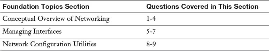
Table 19-1 “Do I Know This Already?” Foundation Topics Section-to-Question Mapping
1. For a class B IP address of 130.88.101.75, what is the network part of the IP address?
a. 130
b. 130.88
c. 130.88.101
d. 101.75
2. Consider the following: 10.122.189.77/255.0.0.0. Which of the following is the equivalent?
a. 10.122.189.77/32
b. 10.122.189.77/24
c. 10.122.189.77/16
d. 10.122.189.77/8
3. Consider the following: 192.168.10.0/255.255.255.0. What is the broadcast address?
a. 192.168.10.0
b. 192.168.10.1
c. 192.168.10.100
d. 192.168.10.255
4. Which protocol offers reliable data package transfer?
a. TCP
b. UDP
c. IGMP
d. ICMP
5. Which of the following commands display your IP address information? (Choose two.)
a. ifconfig
b. route
c. ifup
d. ip
6. Which command displays your default gateway?
a. ifconfig
b. route
c. ifup
d. ip
7. Consider the following entry in the /etc/nsswitch.conf file:
hosts: files dns nis ldap
When the command ping test.com executes, which location will be searched first for hostname resolution?
a. The DNS server
b. The NIS server
c. The LDAP server
d. A local file
8. Which commands allow you to request an IP address as a DNS client? (Choose all that apply.)
a. dhcpcd
b. dhcpclient
c. pump
d. dhcpd
9. Which command allows you to perform a direct DNS query on a specific DNS server?
a. ping
b. traceroute
c. dig
d. getent
Foundation Topics
Conceptual Overview of Networking
An Internet Protocol (IP) is a unique address or locator for a host on a network or on the Internet. All machines and internetworking devices that communicate via Transmission Control Protocol/Internet Protocol (TCP/IP) have an IP address they are known by and communicated through.
To understand how all this works, think of the Internet, which is a large network made up of many interconnected smaller networks. The smallest building block of a network is the host, or any machine that has an IP address and could respond to a ping.
Hosts are considered standalone unless they are connected to a network, and a logical grouping of hosts on a network is usually known as a subnet.
The difference between a subnet and a segment is that a subnet is a logical grouping of hosts, based on their addressing, whereas a segment is usually a physical grouping of hosts attached to the same wire, hub, or switch.
When trying to understand the concepts of networks and hosts, think of a network as a street that has houses on it that represent hosts. If you wanted to find a particular house, you could very well go to that street and begin looking up and down it at the house numbers. Figure 19-1 illustrates a network as a street and hosts as houses.
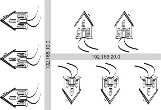
Figure 19-1 Networks and hosts
Following the analogy of networks being streets and hosts on those networks being houses on the streets, an intersection between two streets would be similar to a router or gateway between networks.
In this day of subnet calculators, the temptation is to skip some of this information. None of this is blue-sky knowledge; it’s all applicable to the exam and in most cases to real-life work on a daily basis for a network sysadmin.
Necessary Configuration Information

To participate in more than a single subnet or network, a host needs to have three things:
![]() IP address—Assigned either statically or dynamically, the address must be valid to work.
IP address—Assigned either statically or dynamically, the address must be valid to work.
![]() Network mask—Each logical network or subnet has a particular network mask that helps define where one section of addresses ends and another begins. This is also known as the subnet mask, particularly in a Microsoft environment.
Network mask—Each logical network or subnet has a particular network mask that helps define where one section of addresses ends and another begins. This is also known as the subnet mask, particularly in a Microsoft environment.
![]() Gateway address—Like a door leading out of a room, a gateway address is the local IP associated with a network card or interface on a gateway or router device. Hosts configured with this address as the default gateway send traffic to this address when they need to access remote hosts.
Gateway address—Like a door leading out of a room, a gateway address is the local IP associated with a network card or interface on a gateway or router device. Hosts configured with this address as the default gateway send traffic to this address when they need to access remote hosts.
IP Addresses
An IPv4 IP address consists of 32 bits grouped in four octets of 8 bits, with each octet separated by a dot. This is also known as a dotted quad notation. A particular IP, such as 192.168.10.100, would be expressed as the bit values shown here:
11000000.10101000.00001010.01100100
Bits in an octet have a specific value, and each octet’s bits have the values shown in Figure 19-2.
![]()
Figure 19-2 Bit values in an octet
When a bit in an octet is turned on, that value is added to any other bit values that are turned on to make a decimal number. With the way the bits are arranged, there is only one bit pattern to make any given number.
It might help to visualize these bits as a bank of light switches, each representing a particular value of watts. For example, if you had a bank of light switches with corresponding wattage, you would turn on the switches for 64, 32, and 4 to produce 100 watts of light. Figure 19-3 shows how this would look.
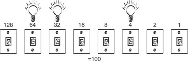
Figure 19-3 The light switch analogy
Typically, you’ll work with IP addresses that have been assigned by a higher authority—either your IT department or corporate headquarters, or even an Internet service provider (ISP).
Networks and Hosts
The basic tenet of all networking with IP addresses is that there will be two portions to any given address that are assigned. Using the previous “streets = networks” and “houses = hosts” analogy, you could look at a host’s address, such as 192.168.1.200, as being broken up into two parts: the street or network address (192.168.1) and the house or host address (.200).
Just as houses on the same street use that street as part of their addresses, a host address is treated as belonging to the network address it shares with the other hosts that belong to that network. To communicate with another system on a shared physical network, both systems must have the same numbers in their network part of their IP address. What determines the network part of the IP is the combination of classes and a feature called subnetting.
Address Class Ranges
Five address class ranges are defined by a Request For Comment (RFC 1918). An address class range is defined by the bit pattern of the first two or three bits in the first octet. This is important because the address class determines the number of hosts possible by default for each of the resulting networks.
A Request For Comment (RFC) documents specifications for Internet standards. As a draft for a particular specification is evaluated, it goes through a process that ends with it becoming an RFC, which is similar to a standard but is often treated as a firm suggestion.
The five address classes are as follows:
![]() A—From 1 to 126; each of these permits up to 16,777,216 host addresses. There can be 126 Class A networks.
A—From 1 to 126; each of these permits up to 16,777,216 host addresses. There can be 126 Class A networks.
![]() B—From 128 to 191; each of these permits up to 65,536 host addresses. There can be 16,382 Class B networks.
B—From 128 to 191; each of these permits up to 65,536 host addresses. There can be 16,382 Class B networks.
![]() C—From 192 to 223; each of these permits up to 254 host addresses. There can be 2,097,150 Class C networks.
C—From 192 to 223; each of these permits up to 254 host addresses. There can be 2,097,150 Class C networks.
![]() D—From 224 to 239. This range is reserved for such activities as multicast and is not usually available for host addresses.
D—From 224 to 239. This range is reserved for such activities as multicast and is not usually available for host addresses.
![]() E—From 240 to 254; this range is reserved for future use.
E—From 240 to 254; this range is reserved for future use.
For those who are asking where the 127 range is, the designers saw fit to leave the entire 127 range for loopback or local host networking only. Yes, that’s 16,777,216 addresses all so someone can ping his local host to see whether IP is working!
Remember that when looking at the massive expanse of IPs available for Class A and Class B address ranges, those are typically broken up into many smaller networks by the use of custom subnet masks, which are covered later in the chapter.
Using the Bits to Determine Class
If you look at the bit pattern for the first octet of an address that’s a Class A, you see the first bit must always be off because no Class A address is above a 126 in the first octet:
Low: 1= 00000001
High: 126 = 01111110
Similarly, a Class B address must have the first bit in the first octet on. All Class B addresses range from 128 and higher:
Low: 128 = 10000000
High: 191 = 10111111
By the same token, no Class C address can exist without the first two bits in the first octet set to on. All Class C addresses range from 192 and higher:
Low: 192 = 11000000
High: 223 = 11011111
Network Masks
I’ve long said that one way to understand IP addresses and their partner network (or subnet) masks is to think of every IP address as consisting of two pieces: a network section and a host section. The network mask sets where network bits end and host-assignable bits begin.
For each class, the point at which a network mask stops is where the network portion of an address ends and the host-assignable portion begins. For example, if you take the address 192.168.1.200 and a default subnet mask, the first three octets represent the network and the last octet is where hosts can be assigned.
Address class ranges come with their own built-in default subnet mask; only one can be the default per range:
![]() A—255.0.0.0 or /8 for the number of bits that represent the network mask
A—255.0.0.0 or /8 for the number of bits that represent the network mask
![]() B—255.255.0.0 or /16 for the number of bits that represent the network mask
B—255.255.0.0 or /16 for the number of bits that represent the network mask
![]() C—255.255.255.0 or /24 for the number of bits that represent the network mask
C—255.255.255.0 or /24 for the number of bits that represent the network mask
LPI follows the industry in its use of either fully spelled-out network masks (255.255.255.0) or using abbreviated notation (/24) to represent any network mask assigned to a host or set of hosts. The number 24 relates to the number of bits used for the subnet mask. This technique that uses the number of bits for the subnet mask is referred to as the Classless Inter-Domain Routing (CIDR) notation.
Be prepared to solve questions that use either method of expressing the network mask.
Using Default Network Masks
As previously mentioned, the place where the network portion of an address ends is where the subnet mask bits stop. If you have a network address such as 192.168.10.0 and a default subnet mask of 255.255.255.0 or /24, a single network (192.168.10.0) exists and the remaining 8 bits outside the network portion are available for assignment to hosts.
It might help to express the network address and then the network mask as a set of bits, like so:
11000000.10101000.00001010.00001010 (The IP)
11111111.11111111.11111111.00000000 (The Subnet Mask)
The boxes highlight the network partition of the IP address. Because the network mask is a /24, or default Class C network mask, you can easily see where the network ends and what’s usable for host addresses. The boundary in this example is the last dot, leaving 8 bits worth of addresses for this single network assignable to hosts.
Gateway Addresses, or “Do I Dial with the Area Code?”
Gateway addresses were previously mentioned as an important part of the host’s networking configuration. If a host needs to communicate on a different network, it must have a portal or door to the network, typically known as a gateway (also known as a router).
Note
The term “gateway” is one that doesn’t have a firm definition in the IT industry. Some IT experts insist that gateway really means “default gateway.” Essentially your system can be connected to multiple networks, each connectable via a router. The default gateway is the router that your system sends network traffic to by default instead of a specific router. However, many IT experts feel the terms “gateway” and “router” are synonymous and that the term “default gateway” distinguishes this router from all others. For this book, we use this definition (gateway = router).
When a host wants to communicate with another host on a network, it inspects the other host’s network address to determine whether that host is on the local network or on another network. If the host exists on the local network, it can be contacted directly; otherwise, a gateway must be used.
Effectively, it’s as if you need to make a phone call to another person and need to find out whether she is in the same area code (local, just dial it) or outside the area code (other network, dial area code first and then the number).
The host uses its network mask to determine whether it needs to send traffic targeted to a remote host via the router for further delivery or whether it can just communicate on the local network to deliver the traffic to the target host.
For example, if you have an IP of 192.168.10.10 and your target host has an IP of 192.168.11.10 (and both use the /24 default network mask), your machine will look at your IP/mask as such:
11000000.10101000.00001010.00001010
11111111.11111111.11111111.00000000
It then applies the same network logic to the target host, such as
11000000.10101000.00001011.00001010
11111111.11111111.11111111.00000000
The network mask is expressed by the digits in the first three octets. If there is even a single bit of difference inside the bits that make up the network mask, the host has to “dial the area code,” or send the traffic to the gateway to have it further delivered. In this case, the networks are different (see the shaded portions), so the gateway is needed.
Broadcast Addresses
All IP networks use the concept of a broadcast to send traffic designed to impact all hosts on that network. For example, if you have a small Class C network represented by the address 192.168.10.0 and a default subnet mask of 255.255.255.0, the network address is 192.168.10.0 but the broadcast address for every host on that network is 192.168.10.255. No matter how small or large, all networks include the concept of the broadcast address, which is not assignable to any host.
Custom Network Masks
The art of custom subnetting is fading, but you have to know how to do at least a Class C custom subnetting problem in your head to determine whether a host has a bad gateway address or how many hosts are possible on a particular network, given the defaults and a custom network mask.
Determining a Custom Network Mask
We discuss two scenarios. In one, you create the subnet map and determine the custom network (subnet) map, and in the other, you solve how many hosts can fit on the network you are assigned.
Scenario 1: Custom Subnetting from Scratch
You are the sysadmin of a small company, and your boss wants to plan a set of networks for your main office and a few other locations. He arranges to rent a Class C network from your network reseller and tells you that you need to have six networks with as many hosts as possible on those networks.
Note
In the example provided, a private IP class is used to avoid any potential problems in a “real world” implementation. 192.168.0.0/16 represents a private network that cannot be directly routable on the Internet.
Your task is to define a new network mask that will be applied to every host on the entire network. All subnets must have a network address, broadcast address, and gateway address, plus as many hosts as possible from the remaining addresses.
Because you know that you are dealing with a Class C network, you can assume that your default network mask that covers 24 bits will allow you to do your custom subnetting in the last 8 bits left over.
Typically, you would be doing host addressing in the last octet, but because you’re breaking up a single network into multiple smaller networks, bits from the last octet are “stolen” or used from the highest value end (128), leaving fewer bits for hosts per resulting subnet.
You know that your network address information is as follows:
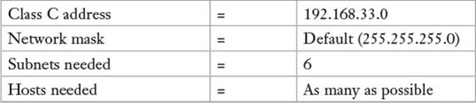
Here are the steps you need to perform:
1. Convert the number of networks (6) to binary = 00000110.
2. Turn all the bits after the 4 bit to on = 00000111.
3. Flip the entire octet from end to end = 11100000.
4. Add the bits together to get the new custom network mask:
128 + 64 + 32 = 224 (the new subnet mask)
5. Start at 0 and use the LSB (least significant bit) or 32 as the increment for the networks (keep in mind that a network’s 0 and 224 might be network and broadcast addresses and thus invalid for use, depending on your networking hardware).
The network addresses (0, 32, 64, and so on) are not assignable as host addresses. The first odd-numbered address (1, 33, 65, and so on) on each of these new networks is the first possible host address.
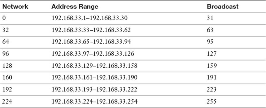
6. You can now assign these ranges to the networks that you build, with each representing 30 host addresses, a network address, and a broadcast address.
The previously listed network numbers represent the subnet or network to which you are assigning hosts. The network address, such as 192.168.33.32, is not assignable to a host. It isn’t even assigned anywhere—it’s agreed upon by the hosts on the network and the custom network mask.
Additionally, the first and last networks (192.168.33.0 and 192.168.33.224) are traditionally not seen as valid for assigning hosts to, unless the networking equipment supports it. Because I can’t predict the hardware capabilities, we use the most common and compatible method.
The address range represents the numbers assignable to hosts, with one exception: The last or odd number on each range is the broadcast address and is not assignable to a host. It’s used to address all hosts when broadcasts are sent over the network.
Scenario 2: How Many Hosts on a Network?
Another situation that might occur is that you are a new consultant for a small company and part of the initiation ritual seems to be setting you down in a cube with a workstation and a slip of paper that has your IP and an abbreviated notation network mask on it and having you discover your default gateway and other IP information.
The IP information you’ve been given is 10.30.200.120/26, and your gateway is supposed to be the last host-assignable IP on your network.
You can convert the /26 into a standard subnet mask by dividing 26 by 8; each 8 becomes a 255 and the remainder of 2 becomes a .192. In other words, convert the 26 into the number of bits in a subnet mask starting from the leftmost bit and moving right.
To solve this, you should do a quick subnetting problem, such as
1. The 10.30.200.180 address is a Class A address, but the network mask of 26 translates into a 255.255.255.192, or a small chunk of the original 10.0.0.0 network.
2. Turn the 192 into the bit values = 1100000.
3. The smallest bit is 64, so the subnets increment by 64, starting at 0.
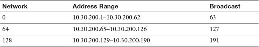
4. After you have your network (180 falls in the 129–191 network) you can stop, unless you just have to finish the networks.
Your network address is 10.30.200.128, the first addressable host IP is 10.30.200.129, the last addressable host IP is 10.30.200.190, and the broadcast address is 10.30.200.191. There are 62 host IP addresses on your subnet.
Be prepared to reread questions to see whether they want to know all IPs on a network or whether you leave out the router and broadcast address. If you’re asked for the number of IPs that could be assigned to hosts, it’s always an even number; if you are to disregard or leave out the router/gateway address, it has to be an odd number.
Additional Protocols
There are many networking protocols, but just four are critical to know for the exam. Recall that a protocol is a set of rules that define communication between two devices. You should be familiar with the following protocols:
![]() IP (Internet Protocol)—The Internet Protocol handles the addressing and communication between devices on a network. It defines IP addresses, subnetting, and routing.
IP (Internet Protocol)—The Internet Protocol handles the addressing and communication between devices on a network. It defines IP addresses, subnetting, and routing.
![]() TCP (Transmission Control Protocol)—TCP is designed to be a complement protocol to the Internet Protocol. Often the two protocols are described as the TCP/IP suite. While IP focuses on the addressing of systems, TCP focuses on the transport of data packages. It is often contrasted with the User Datagram Protocol (UDP) as they both perform similar functions. TCP differs from UDP in that the data packages are considered “reliable” because TCP performs error checking to make sure all data packages arrive at the destination. While this results in additional overhead, it is necessary for situations when the data must get through without errors.
TCP (Transmission Control Protocol)—TCP is designed to be a complement protocol to the Internet Protocol. Often the two protocols are described as the TCP/IP suite. While IP focuses on the addressing of systems, TCP focuses on the transport of data packages. It is often contrasted with the User Datagram Protocol (UDP) as they both perform similar functions. TCP differs from UDP in that the data packages are considered “reliable” because TCP performs error checking to make sure all data packages arrive at the destination. While this results in additional overhead, it is necessary for situations when the data must get through without errors.
![]() UDP (User Datagram Protocol)—Designed to be a complement protocol to the Internet Protocol. Often the two protocols are described as the UDP/IP suite. While IP focuses on the addressing of systems, UDP focuses on the transport of data packages. It is often contrasted with TCP as they both perform similar functions. UDP differs from TCP in that the data packages are sent connectionless, so no error checking is performed.
UDP (User Datagram Protocol)—Designed to be a complement protocol to the Internet Protocol. Often the two protocols are described as the UDP/IP suite. While IP focuses on the addressing of systems, UDP focuses on the transport of data packages. It is often contrasted with TCP as they both perform similar functions. UDP differs from TCP in that the data packages are sent connectionless, so no error checking is performed.
![]() ICMP (Internet Control Message Protocol)—The primary focus of this protocol is to allow networking devices, such as routers, the capability to send error messages. An example would be when a router is unreachable. ICMP also provides the capability to perform queries, such as when an administrator uses the ping command to determine whether a remote system is reachable.
ICMP (Internet Control Message Protocol)—The primary focus of this protocol is to allow networking devices, such as routers, the capability to send error messages. An example would be when a router is unreachable. ICMP also provides the capability to perform queries, such as when an administrator uses the ping command to determine whether a remote system is reachable.
Common Ports
For the exam you are expected to know what a network port is and be familiar with common network ports. To understand ports, consider the following: You decide to connect to a remote system via SSH. The remote system has many network-based services (FTP, SSH, mail server, and so on) running. How does the SSH server on the remote system know that you are trying to connect via SSH rather than the other network-based services?
The answer is that the SSH server listens to a port. A port is a numeric value assigned to a service. Remember the analogy of how an IP address is like a house address? In fact, it is more like an apartment address with the port numbers being the apartment number that you are trying to access.
How a service determines which port to listen to is complex. Traditionally, the service was supposed to look at the entries in the /etc/services file. Example 19-1 shows a small portion of this file:
Example 19-1 An Example of the /etc/services File
# The latest IANA port assignments can be gotten from
# http://www.iana.org/assignments/port-numbers
# The Well Known Ports are those from 0 through 1023.
# The Registered Ports are those from 1024 through 49151
# The Dynamic and/or Private Ports are those from 49152 through 65535
#
# Each line describes one service, and is of the form:
#
# service-name port/protocol [aliases ...] [# comment]
tcpmux 1/tcp # TCP port service
multiplexer
tcpmux 1/udp # TCP port service
multiplexer
rje 5/tcp # Remote Job Entry
rje 5/udp # Remote Job Entry
Based on this output, the tcpmux (TCP port service multiplexer) service is to use TCP and UDP port #1.
The reality is that few services actually look at this file. Most of them have settings in their configuration files to specify which port to listen to (although most services use a default that matches the entry in the /etc/services file).
Port numbers 0-1023 are designated as well-known ports. These ports are supposed to be assigned to commonly used network services (sometimes referred to as legacy services). Ports 1024-49151 are called registered ports. These ports are assigned by the Internet Assigned Numbers Authority (IANA) to provide some sort of standardization of ports. The last range of port numbers, 49152-65535, are called dynamic (or private or ephemeral) ports. These cannot be “reserved” and can be used for any purpose.
For the exam, you should be aware of the following port numbers and the services that commonly utilize the ports:
![]() 20 & 21—FTP
20 & 21—FTP
![]() 22—SSH
22—SSH
![]() 23—Telnet
23—Telnet
![]() 25—SMTP
25—SMTP
![]() 53—DNS
53—DNS
![]() 80—HTTP
80—HTTP
![]() 110—POP3
110—POP3
![]() 123—NTP
123—NTP
![]() 139—NETBIOS
139—NETBIOS
![]() 143—IMAP
143—IMAP
![]() 161 and 162—SNMP
161 and 162—SNMP
![]() 389—LDAP
389—LDAP
![]() 443—HTTPS
443—HTTPS
![]() 465—SMTPS
465—SMTPS
![]() 514—SYSLOG
514—SYSLOG
![]() 636—LDAPS
636—LDAPS
![]() 993—IMAPS
993—IMAPS
![]() 995—POP3S
995—POP3S
IPv6
The Internet Protocol discussed previously in this chapter was actually IPv4 (Internet Protocol, version 4). This IP has been widely used on both local networks and the Internet for decades (since 1982). A newer version of this protocol was introduced in the mid-1990s: IPv6. The two protocols have many differences, and IPv6 is considered a great improvement over IPv4. However, implementing this newer protocol in the huge network called the Internet has proved difficult.
Note
Google has a graph that shows how many of its users have some form of IPv6 connectivity. As of mid-2015, this number is at about 7%, up 5% from 2013, but still a low percentage.
For the LPIC-1 exam, you should know some of the difference between IPv6 as well as some of the basic commands. While most examples throughout this chapter focus on IPv4, there are some IPv6 examples as well.
The major differences between IPv4 and IPv6 include
![]() Address scheme—IPv4 uses a 32-bit number for addressing (Dotted Decimal Notation: 192.168.1.1). IPv6 uses a 128-bit number for addressing (Hexadecimal Notation: 3FFE:F200:0134:AB00:0143:1111:8901:AAAA). IPv4 is limited to about 4.2 billion addresses (much less when you consider IP addresses lost to subnetting), while IPv6 has a considerably higher limit (2128 or 340,282,366,920,938,463,463,374,607,431,768,211,456). This difference is considered the “big one” by many because with so many devices connecting to the Internet (think computers, cell phones, tablets, routers, cable boxes, etc.), 4.2 billion unique addresses is inadequate.
Address scheme—IPv4 uses a 32-bit number for addressing (Dotted Decimal Notation: 192.168.1.1). IPv6 uses a 128-bit number for addressing (Hexadecimal Notation: 3FFE:F200:0134:AB00:0143:1111:8901:AAAA). IPv4 is limited to about 4.2 billion addresses (much less when you consider IP addresses lost to subnetting), while IPv6 has a considerably higher limit (2128 or 340,282,366,920,938,463,463,374,607,431,768,211,456). This difference is considered the “big one” by many because with so many devices connecting to the Internet (think computers, cell phones, tablets, routers, cable boxes, etc.), 4.2 billion unique addresses is inadequate.
Note
A feature in IPv4 addresses the limited number of Internet-connectable addresses: NAT (Network Address Translation). With this technology, a private network can use nonroutable IP addresses and funnel all Internet connections via a router that “translates” the private IP addresses into a single public IP address. With this technology you could connect hundreds of devices to the Internet with a single public IP address. This technology is considered by some to be the reason why IPv6 hasn’t really taken hold quickly.
![]() Routing—Routing in IPv6 is considered more efficient.
Routing—Routing in IPv6 is considered more efficient.
![]() Security—IPv6 has security built in. For IPv4, security is implemented as a separate feature and is not as strong as IPv6.
Security—IPv6 has security built in. For IPv4, security is implemented as a separate feature and is not as strong as IPv6.
![]() Autoconfigure—With IPv4, addresses are either assigned statically (via a configuration file) or dynamically (via a DHCP server). With IPv6, both of these techniques are available, but the IPv6 protocol also allows for autoconfiguration, making administration much easier.
Autoconfigure—With IPv4, addresses are either assigned statically (via a configuration file) or dynamically (via a DHCP server). With IPv6, both of these techniques are available, but the IPv6 protocol also allows for autoconfiguration, making administration much easier.
![]() Header—The beginning part of a network package is called the header. The header for IPv6 packages is much more robust and requires less processing overhead.
Header—The beginning part of a network package is called the header. The header for IPv6 packages is much more robust and requires less processing overhead.
Managing Interfaces
A Linux machine has a default interface called the loopback or local interface. The device appears as lo (that’s a lowercase L, not a number one) and can be configured like other interfaces, with the main difference being that the loopback is never going to connect to a network. The loopback interface is only there so your machine can have IP bound to an interface even if it’s not otherwise configured to use a network card.
Real life, bosses, and the exam will require you to be able to set your IP via the interface configuration files or even statically configure the interface from the command line.
Viewing IP Information
The primary tool for viewing your IP information is the ifconfig command. By default, ifconfig shows all active interfaces, including the loopback. To display the interfaces on a Linux machine, you would enter the ifconfig command.
This produces output similar to that shown in Example 19-2.
Example 19-2 Example of an ifconfig Command’s Output
eth0 flags=4163<UP,BROADCAST,RUNNING,MULTICAST> mtu 1500
inet 192.168.1.21 netmask 255.255.255.0 broadcast
192.168.1.255
inet6 fe80::a00:27ff:fe52:2878 prefixlen 64 scopeid
0x20<link>
ether 08:00:27:52:28:78 txqueuelen 1000 (Ethernet)
RX packets 310881 bytes 279637701 (266.6 MiB)
RX errors 0 dropped 0 overruns 0 frame 0
TX packets 64257 bytes 6386376 (6.0 MiB)
TX errors 0 dropped 0 overruns 0 carrier 0 collisions 0
lo: flags=73<UP,LOOPBACK,RUNNING> mtu 65536
inet 127.0.0.1 netmask 255.0.0.0
inet6 ::1 prefixlen 128 scopeid 0x10<host>
loop txqueuelen 0 (Local Loopback)
RX packets 751 bytes 126427 (123.4 KiB)
RX errors 0 dropped 0 overruns 0 frame 0
TX packets 751 bytes 126427 (123.4 KiB)
TX errors 0 dropped 0 overruns 0 carrier 0 collisions 0
In the previous output, you see a wealth of information; particularly of note is the eth0 interface. Pay attention to the following information:
![]() ether—This displays the hardware address, also known as the Media Access Control (MAC). In any case, it’s the 48-bit physical address of the interface hardware.
ether—This displays the hardware address, also known as the Media Access Control (MAC). In any case, it’s the 48-bit physical address of the interface hardware.
![]() inet—The address assigned to the interface.
inet—The address assigned to the interface.
![]() broadcast—The broadcast address for the network this machine is on; it’s entirely dependent on the network mask.
broadcast—The broadcast address for the network this machine is on; it’s entirely dependent on the network mask.
![]() netmask—The network mask, or how the system knows the logical network it’s on.
netmask—The network mask, or how the system knows the logical network it’s on.
Also note the receive (RX) and transmit (TX) statistics and collisions that might exist for a particular interface. I’ve not mentioned the local interface; it’s there but doesn’t impact the machine’s network presence.
If you see any output from the ifconfig command on the exam, inspect it carefully for configuration errors, collisions, and whether the interface state is up or down. LPI doesn’t use screen real estate lightly, so that information will be key to the answer to the question, whatever it is.
Be aware of the ip command; it is designed to replace many of the commands that you see in this chapter. For example, the ip command can also display network configuration data, just like the ifconfig command. If you execute the ip addr show command, the output looks like that shown in Example 19-3.
Example 19-3 Example of ip addr show Command Output
1: lo: <LOOPBACK,UP,LOWER_UP> mtu 16436 qdisc noqueue state UNKNOWN
link/loopback 00:00:00:00:00:00 brd 00:00:00:00:00:00
inet 127.0.0.1/8 scope host lo
inet6 ::1/128 scope host
valid_lft forever preferred_lft forever
2: eth0: <BROADCAST,MULTICAST,UP,LOWER_UP> mtu 1500 qdisc pfifo_fast
state UP qlen 1000
link/ether 08:00:27:08:ea:ff brd ff:ff:ff:ff:ff:ff
inet 192.168.1.22/24 brd 192.168.1.255 scope global eth0
inet6 fe80::a00:27ff:fe08:eaff/64 scope link
valid_lft forever preferred_lft forever
Red Hat Interface Configuration
On a Red Hat machine, the /etc/sysconfig/network-scripts directory contains the scripts used to configure and bring up and down the interfaces on the machine.
Note
There have been recent changes in networking configuration files and utilities on Red Hat-based systems. The following applies to Red Hat Enterprise Linux 6.x (discussion of Red Hat Enterprise 7.x is not included in this section). It is important to note that these specific networking files in this section are not exam testable; they are included to provide you with a basic understanding of how specific distributions are different.
For example, if you have an eth0 interface you need to configure with a static IP and other configuration, you could modify the /etc/sysconfig/network-scripts/ifcfg-eth0 file. This file can also be modified by a tool called system-config-network.
To display the ifcfg-eth0 file, use
cat /etc/sysconfig/network-scripts/ifcfg-eth0
With a static configuration for IPv4, you see output similar to the following:
DEVICE=eth0
ONBOOT=yes
BOOTPROTO=static
IPADDR=192.168.1.73
NETMASK=255.255.255.0
GATEWAY=192.168.1.1
With a static configuration for IPv6, you see output similar to the following (for autoconfiguration, just specify the first line):
IPV6INIT=yes
IPV6ADDR=3FFE:F200:0134:AB00:0143:1111:8901:0002
IPV6_DEFAULTGW=3FFE:F200:0134:AB00:0143:1111:8901:0001
If the interface is configured for DHCP, you see output similar to the following for IPv4:
DEVICE=eth0
ONBOOT=yes
BOOTPROTO=dhcp
If the interface is configured for DHCP, you see output similar to the following for IPv6:
IPV6INIT=yes
DHCPV6C=yes
Whichever method you decide to use can be implemented by editing this file and setting the parameters you want. The parameters are self-explanatory, with the possible exception of the BOOTPROTO parameter. The BOOTPROTO parameter, when set to either static or dhcp, tells the network daemon how to configure this interface, either by reading the other parameters in the ifcfg-eth0 file or by using DHCP to get the address.
After changing these settings, restart networking by executing service network restart.
This restarts the networking and brings the interfaces down and back up again.
Debian Interface Configuration
Debian uses a different style of configuring interfaces. Instead of several smaller scripts or configuration files, Debian uses the /etc/network/interfaces file for all interfaces. Although Debian doesn’t include the system-config-networking utility by default, the netcardconfig program is included in some Debian distributions and does roughly the same tasks.
Note
It is important to note that these specific networking files in this section are not exam testable; they are included to provide you with a basic understanding of how specific distributions are different.
To see the contents of this file, use
cat /etc/network/interfaces
This produces output similar to that shown in Example 19-4.
Example 19-4 Example of Contents of the /etc/network/interfaces File
# /etc/network/interfaces -- configuration file for ifup(8), ifdown(8)
# The loopback interface
# automatically added when upgrading
auto lo eth0
iface lo inet loopback
iface eth0 inet static
address 192.168.15.5
netmask 255.255.255.0
network 192.168.15.0
broadcast 192.168.15.255
gateway 192.168.15.2
Each interface defined in the interfaces file starts with the keyword iface, then the name of the interface, the type of address (inet for IP, ipx for IPX, and inet6 for IPv6), and the method for the interface (either static or dhcp).
After configuring the interfaces file with the correct parameters, it’s recommended to restart the network daemon with /etc/init.d/networking restart.
This restarts the networking and brings the interfaces down and back up again.
Notice that the Debian interfaces file contains the gateway address but doesn’t use uppercase letters like Red Hat does. Nor does Debian use an equal sign (=) between the parameter and the value in the interfaces file. Debian also uses the scripts as an input or source file, whereas Red Hat actually executes its configuration scripts.
It’s important to note that, although Debian does primarily use the previous method, an instance of the file /etc/sysconfig/network-scripts/ifcfg-eth0 is often found on the Debian machine. You need to read the documentation for your distribution or method to determine what relationship exists between the two. You can safely assume that this won’t be an issue on the exam as the networking questions on the exam are distribution neutral.
Viewing and Configuring Gateway Addresses
The default gateway is used for sending traffic to an interface that is the doorway or gateway to the rest of your networks, hence the name. A default gateway is necessary because you don’t want to have static routes on all your machines for every destination network—that would be unwieldy and quickly become outdated.
Viewing the Default Gateway
To view the default gateway configured on your machine, you can use either the route command or the netstat –r command.
This displays output similar to the following:
Kernel IP routing table
Destination Gateway Genmask Flags MSS Window irtt Iface
192.168.1.0 * 255.255.255.0 U 40 0 0 eth0
127.0.0.0 * 255.0.0.0 U 40 0 0 lo
default 192.168.1.2 0.0.0.0 UG 40 0 0 eth0
This is an important set of output. Without a properly configured gateway, your machine is capable of reaching hosts only on your local network.
The line that begins with 192.168.1.0 is the actual network address of your subnet or network. Any network packages sent to a machine on this network are just broadcast on the local network. However, any network packages sent to a machine on a different network are sent to the default gateway of 192.168.1.2.
Beware of any questions or answers on the exam that try to trick you into thinking that the actual IP of the gateway is 0.0.0.0. It’s not; that’s just the method that IP addressing schemes use to represent the default gateway when you are looking for a destination network for which a route isn’t configured.
Configuring a Default Gateway
As you have seen in the configuration files for both Red Hat and Debian, a valid GATEWAY or gateway parameter and a value of an IP can configure a valid gateway for the interface.
On a Red Hat machine, you can edit either the /etc/sysconfig/network file or the /etc/sysconfig/network-scripts/ifcfg-eth0 file and add the GATEWAY entry:
GATEWAY=10.0.0.1
Debian uses the /etc/network/interfaces file to set each individual interface’s gateway value.
On both types of systems, you can add a default gateway manually with the following command:
route add default gw 10.0.0.1
It’s important to note the syntax for the previous command:
![]() route—The route command, which is used for many things related to establishing, viewing, and removing routes to other networks.
route—The route command, which is used for many things related to establishing, viewing, and removing routes to other networks.
![]() add—Used to add the default gateway. Other options include del to delete a particular route.
add—Used to add the default gateway. Other options include del to delete a particular route.
![]() default—The default gateway is the one used if no other route exists or matches the target address.
default—The default gateway is the one used if no other route exists or matches the target address.
![]() gw—Notes that the entry is a gateway to the rest of the networks and traffic should be routed through this interface.
gw—Notes that the entry is a gateway to the rest of the networks and traffic should be routed through this interface.
![]() 10.0.0.1—Replaced with your gateway address, or the resolvable domain name of the host that provides this functionality.
10.0.0.1—Replaced with your gateway address, or the resolvable domain name of the host that provides this functionality.
Expect to troubleshoot, configure, or fill in the blank on a question about a default gateway. This type of question appears several times on the exam, as either fill-in-the-blank or multiple choice (and often both) stated slightly differently.
Local Name Configuration
Local name configuration is a mish-mash of different files, the most notable of which are
![]() /etc/hosts
/etc/hosts
![]() /etc/resolv.conf
/etc/resolv.conf
![]() /etc/nsswitch.conf
/etc/nsswitch.conf
Note
These files are distribution neutral and can definitely show up on the exam!
These three files are used to configure how local name resolution occurs. Figure 19-4 shows the relationship between these files and how they use each other to resolve the name for a host to which a client software application needs to connect.
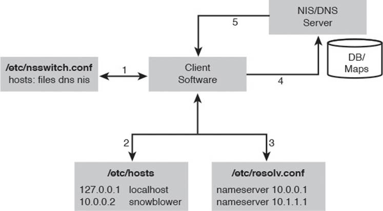
Figure 19-4 Name resolution diagram
The numbered steps in Figure 19-4 represent the steps that would be followed during a normal name resolution. The following examples show how different variations would work on a system with this configuration.
For example, we issue the ping snowblower command on a host with the sample configuration shown in Figure 19-4.
When a name is used instead of an IP, the client software asks the system to resolve that name to an IP address. The system follows these steps:
1. The system first refers to the /etc/nsswitch.conf file and the hosts: line for the order in which it should look for the name’s resolution. In Figure 19-4, the hosts: line is set to first look at the local files, then dns, and then nis:
hosts: files dns nis
2. The system looks in the file /etc/hosts for the resolution of the name snowblower to an IP; in this case, it finds a matching entry with an IP address of 10.0.0.2.
3. The system returns the IP address to the client and the name resolution portion of the transaction is complete.
As a more complex example, let’s see what happens if we issue the ping shpdoinkle command on a host that has the previous configuration.
The system follows the same general set of steps, with an addition:
1. The system first refers to the /etc/nsswitch.conf file and the hosts: line for the order of resolution.
2. The /etc/hosts file is inspected for a matching entry.
3. When none is found, the /etc/nsswitch.conf file is read and the next option for resolution is found to be dns.
4. The system then reads the /etc/resolv.conf file for the name server entries, with an upper practical limit of three expected. The /etc/resolv.conf file defines the DNS servers used by this system.
5. The system queries the first found name server for the resolution of the name. If the name is resolved, resolution is halted. If the first name server doesn’t reply in a reasonable amount of time, it tries the next configured name server until no entries remain; if no resolution is found, it fails.
6. If the name is resolved, the system returns the IP address to the client and the name resolution portion of the transaction is completed.
7. If the DNS queries all fail, then the NIS server is queried because the last entry on the hosts: line is nis. This assumes that an NIS server is configured for this system.
Note
Just because an entry in the local files resolves a hostname to an IP address doesn’t mean that the IP address is the correct one for the target host! A prime troubleshooting topic on the exam is having name resolution problems for hosts right after switching to using domain name services (DNS) for name resolution. The host does not query further if a resolution is made.
Other name resolution-related files can be used on a Linux system, but most are, by default, not on the Red Hat or Debian systems you see these days:
![]() /etc/hostname—Used to statically store the fully qualified domain name, such as snowblower.brunson.org. Note that this file is included in the exam objectives while the other two files are not.
/etc/hostname—Used to statically store the fully qualified domain name, such as snowblower.brunson.org. Note that this file is included in the exam objectives while the other two files are not.
![]() /etc/networks—Used to map a network name to an otherwise IP-related network, more often used in Solaris environments than Linux.
/etc/networks—Used to map a network name to an otherwise IP-related network, more often used in Solaris environments than Linux.
![]() /etc/host.conf—Similar in function to the /etc/nsswitch.conf file. It sets the order in which resolution sources are searched (this file is overridden by /etc/nsswitch.conf).
/etc/host.conf—Similar in function to the /etc/nsswitch.conf file. It sets the order in which resolution sources are searched (this file is overridden by /etc/nsswitch.conf).
Network Configuration Utilities
A number of commands are used to view, configure, or troubleshoot your network configuration, including
![]() ifconfig—Used to set and display the host’s IP address and network mask.
ifconfig—Used to set and display the host’s IP address and network mask.
![]() ifup—Used to bring an interface up.
ifup—Used to bring an interface up.
![]() ifdown—Used to bring an interface down.
ifdown—Used to bring an interface down.
![]() ip—Designed to replace the collection of commands (ifconfig, ifup, ifdown, route, and so on).
ip—Designed to replace the collection of commands (ifconfig, ifup, ifdown, route, and so on).
![]() route—Used to set and display the host’s routing and gateway information.
route—Used to set and display the host’s routing and gateway information.
![]() dhcpcd, dhclient, and pump—Used (variously) to initiate, release, or renew the client’s DHCP-assigned address(es).
dhcpcd, dhclient, and pump—Used (variously) to initiate, release, or renew the client’s DHCP-assigned address(es).
![]() host, nslookup, and dig—Used to look up DNS names and return information about the targeted host.
host, nslookup, and dig—Used to look up DNS names and return information about the targeted host.
![]() hostname—Used to set or view the host’s hostname; other name utilities can create name-related links to this file.
hostname—Used to set or view the host’s hostname; other name utilities can create name-related links to this file.
![]() netstat—Used to view information about the networking subsystem, statistics, and attached hosts/ports.
netstat—Used to view information about the networking subsystem, statistics, and attached hosts/ports.
![]() ping—The simplest way to establish that a host is alive and responding; essentially a network “hello.”
ping—The simplest way to establish that a host is alive and responding; essentially a network “hello.”
![]() traceroute—Used to determine the path, names, and statuses of the routing devices that a set of traffic uses to reach a given remote host.
traceroute—Used to determine the path, names, and statuses of the routing devices that a set of traffic uses to reach a given remote host.
![]() tcpdump—Used to capture and inspect the contents of packets from the network.
tcpdump—Used to capture and inspect the contents of packets from the network.
Note
All these utilities are useful; however, not all are included in the exam objectives. Review the objectives carefully when studying for the exam.
Network Utility Examples
Many of the previously listed utilities are complex and robust programs and could be the subject of a much longer book. This section consists of quick examples and relevant exam tips for these utilities.
The ifconfig Command
The ifconfig command is used primarily to view or set the IPs for a host. You can set everything but the default gateway with this command, including the bringing up or activation of the interface.
To set up the eth0 interface to communicate on the 192.168.33.0 network with an IP of 192.168.33.2 and a network mask of 255.255.255.0 and to activate the interface, use the following command:
ifconfig eth0 192.168.33.2 netmask 255.255.255.0 up
The ifconfig command displays the working or activated interfaces for the system. If any are down or not activated, they can be shown with the -a switch—for example:
ifconfig -a
The route Command
The route command was featured earlier in this chapter for the purposes of adding default gateways, but it’s also used in defending your system from an attack in progress.
When you have a host that is being attacked by a denial-of-service attack, or some sort of denial of service is being attempted, the quickest action you can take is to add a route that causes any responses to the attacker’s IP to be routed through the loopback address, effectively causing your system to misroute the traffic to that host.
To stop a particular host from attacking a server, open a shell on the server and enter the following (where 10.1.1.69 is the attacker’s IP) command:
route add 10.1.1.69 lo
Any of the traffic that your host would have sent in return to the attacking host is now sent to the loopback network, where it times out and the attacking host times out and gives up on your poor server.
Obviously, this is not a long-term solution, but try this on your local network with the ping command from a host and type the previous command on the host being attacked. You see that the attacking or pinging host suffers a time-out very quickly.
Note
Although not directly related to the route command, if you need to turn on IP forwarding on a host, one of the ways is to echo a “1” into the /proc/sys/net/ipv4/ip_forward file. This effectively turns on the forwarding of traffic between the different interfaces on the machine. For example:
echo 1 > /proc/sys/net/ipv4/ip_forward
DHCP Client Tools
This section assumes that you know how to use DHCP and that you understand that IPs are leased from the DHCP server by the client for a specified period of time, timing out and expiring unless renewed by the client utilities mentioned later in this section.
Depending on the distribution, to cause an interface to request a DHCP address, one or more of the following DHCP-related programs must be present:
![]() dhcpcd
dhcpcd
![]() dhclient
dhclient
![]() pump
pump
The dhcpcd (DHCP Client Daemon) program runs on the client to help configure the client’s IP and watch the lease time-out period, requesting a new address lease when needed for the client.
The /sbin/dhcpcd daemon is typically invoked from the startup scripts or from the /sbin/ifup; this utility executes the commands in the /etc/sysconfig/network-scripts/ifup script on a Red Hat machine and the /etc/network/interfaces script on a Debian machine.
If you need to immediately renew or refresh your client’s address lease, you can restart or “HUP” the dhcpcd daemon with the following command:
dhcpcd -k
This kills and restarts the daemon, causing it to either recontact the DHCP server and get a new lease or reconfirm the old one.
The dhclient program is used by some distributions as a method of getting a DHCP lease, using the dhclient.conf file for configuration, including its time-out and retry values. The dhclient command attempts to obtain a lease for all interfaces set up to use DHCP, keeping the lease information in the dhclient.leases file.
Using dhclient is simple. If you need a new address, restart the network services and run
dhclient
The pump command is another of the possible variations you can use to obtain a DHCP lease. To obtain a new address with pump, use the command as such:
pump
Of course, after running the available client tool, it’s best to confirm that an address was actually obtained or renewed with the ifconfig or ip command.
The host, getent, and dig Commands
The host, getent, and dig commands are another set of commands used for a particular function—name lookups or troubleshooting of hostname or fully qualified domain names.
The host command is simple and has little use other than to return the resolved IP address for a hostname:
host brunson.org
This returns output like the following:
brunson.org has address 192.168.1.1
You can use options to gather further information about the targeted host or domain, but these options are not testable on the LPIC-1 exam.
The host command is designed specifically to perform DNS lookups. This can pose problems when your system resolves hostnames from both DNS servers and from the local host file (/etc/hosts). Conversely, the getent command can search both locations (as well as hostname to IP address translation on NIS and LDAP servers).
The getent command uses the aforementioned /etc/nsswitch.conf file to determine the search order. For example, consider the following entry in this file:
hosts: files dns
Based on the previous output, the getent command first searches the local hosts file and then, if the lookup isn’t found, performs a DNS query. The command is executed like the following:
getent hosts brunson.org
If you want to perform only DNS queries, the dig command is the correct tool. The dig command is usable in a command-line mode or batch mode for larger sets of target servers. When you use the dig command, follow this syntax:
dig server name type
The server is the domain or server IP you are querying for information. Typically, you use the server section only if you need to specify a particular one. The name is the actual domain or host you are searching for, such as lpi.org. The type allows you to specify whether you want to see MX, SIG, A, or ANY record types.
Using the dig command is relatively simple. To find just the MX records (mail server) for the brunson.org domain, use the dig brunson.org MX command, which returns the output shown in Example 19-5.
Example 19-5 Example of dig Command Output
; <<>> DiG 9.2.4rc2 <<>> brunson.org MX
;; global options: printcmd
;; Got answer:
;; ->>HEADER<<- opcode: QUERY, status: NOERROR, id: 41375
;; flags: qr rd ra; QUERY: 1, ANSWER: 1, AUTHORITY: 2, ADDITIONAL: 3
;; QUESTION SECTION:
;brunson.org. IN MX
;; ANSWER SECTION:
brunson.org. 3598 IN MX 0 brunson.org.
;; AUTHORITY SECTION:
brunson.org. 1835 IN NS NS3.INDYSERV.NET.
brunson.org. 1835 IN NS NS4.INDYSERV.NET.
;; ADDITIONAL SECTION:
brunson.org. 1835 IN A 207.238.213.12
NS3.INDYSERV.NET. 167293 IN A 207.238.213.33
NS4.INDYSERV.NET. 167293 IN A 207.238.213.34
;; Query time: 65 msec
;; SERVER: 192.168.33.2#53(192.168.33.2)
;; WHEN: Wed May 12 11:31:16 2004
;; MSG SIZE rcvd: 141
The output for a dig query is structured, consisting of the following:
![]() HEADER—This contains information about the dig environment and options.
HEADER—This contains information about the dig environment and options.
![]() QUESTION—This section simply echoes back your query.
QUESTION—This section simply echoes back your query.
![]() ANSWER—This section is the reply to your query.
ANSWER—This section is the reply to your query.
![]() AUTHORITY—This section shows the servers that are the authoritative name servers for the requested target.
AUTHORITY—This section shows the servers that are the authoritative name servers for the requested target.
![]() ADDITIONAL—This is a catch-all section, typically displaying the name servers for the target.
ADDITIONAL—This is a catch-all section, typically displaying the name servers for the target.
![]() STATISTICS—This section shows you how much time it took in milliseconds or seconds to answer the query as well as the date and time of the query.
STATISTICS—This section shows you how much time it took in milliseconds or seconds to answer the query as well as the date and time of the query.
Expect to see host, getent, and dig on the exam, especially the ability to see a particular type of host with the dig command.
Hostname Utilities
The hostname command is used to view and set the host and domain names for a system. The system’s hostname can be set by this command, or it can be set in the boot process by various scripts depending on the distribution and version.
The hostname command is linked to the following commands:
![]() domainname
domainname
![]() dnsdomainname
dnsdomainname
![]() nisdomainname
nisdomainname
![]() ypdomainname
ypdomainname
You can also use options to the hostname command to show information, such as the following command:
hostname --fqdn
This returns similar output to the following:
localhost.localdomain
Using netstat
The netstat command is useful for determining statistics for network interfaces, connections to and from the local machine, and a lot of other information.
Using netstat without any options outputs a list of the open sockets on the system, but the most useful output is produced when you use options or combine them for richer information and troubleshooting.
The netstat command has lot of options; the most relevant of the options include the following:
![]() -t—Shows TCP statistics
-t—Shows TCP statistics
![]() -r—Shows the routing table
-r—Shows the routing table
![]() -a—Shows all the sockets on all functioning interfaces
-a—Shows all the sockets on all functioning interfaces
![]() -c—Shows a refreshing (every 1 second) view of statistics for usage
-c—Shows a refreshing (every 1 second) view of statistics for usage
![]() -p—Shows the name and PID of the program related to each socket (very useful!)
-p—Shows the name and PID of the program related to each socket (very useful!)
To see all the interfaces’ usage statistics, use the netstat -s command, which returns output similar to
(Output truncated for space)
Ip:
216167 total packets received
0 forwarded
0 incoming packets discarded
216092 incoming packets delivered
104652 requests sent out
80 dropped because of missing route
The netstat command is also used for viewing the routing table for the system:
netstat -r
This returns output similar to the following:
Kernel IP routing table
Destination Gateway Genmask Flags MSS Window irtt Iface
192.168.1.0 * 255.255.255.0 U 40 0 0 eth0
127.0.0.0 * 255.0.0.0 U 40 0 0 lo
default 192.168.1.1 0.0.0.0 UG 40 0 0 eth0
The final and most exam-related use of the netstat command is the detection and troubleshooting of connections to and from your machine. The output from the next command is voluminous, so I’ve truncated it to a usable portion, while maintaining a reasonable facsimile of what you see on your system.
To see what your system has for connections, use the following command (using the head command and line numbering to keep the output manageable):
netstat -a | head -n 20
This returns output similar to that shown in Example 19-6.
Example 19-6 Example of netstat Command Output
1 Active Internet connections (servers and established)
2 Proto Recv-Q Send-Q Local Address Foreign Address ________ State
3 tcp 0 0 *:pop3s *:* LISTEN
4 tcp 0 0 *:netbios-ssn *:* LISTEN
5 tcp 0 0 *:sunrpc *:* LISTEN
6 tcp 0 0 192.168.15.5:domain *:* LISTEN
7 tcp 0 0 *:ssh *:* LISTEN
8 tcp 0 0 *:smtp *:* LISTEN
9 tcp 0 0 *:7741 *:* LISTEN
10 tcp 0 1 192.168.15.5:36651 206.235.223.112:smtp SYN
11 tcp 0 48 192.168.15.5:ssh 192.168.15.1:4417 ESTABL
12 tcp 0 0 192.168.15.5:36619 www.certmag.com:www ESTABL
13 0 1 192.168.15.5:36657 206.235.223.112:pop3 SYN
14 tcp 0 1 192.168.15.5:36653 206.235.223.112:pop3 SYN
15 tcp 0 0 192.168.15.5:36594 moviesunlim:www ESTABL
16 tcp 0 0 192.168.15.5:36595 moviesunlim:www ESTABL
The output from the netstat command is divided up into a number of columns, including
![]() Proto—The protocol used, typically TCP or UDP.
Proto—The protocol used, typically TCP or UDP.
![]() Recv-Q—The bytes not yet received by the service or client attached to the socket.
Recv-Q—The bytes not yet received by the service or client attached to the socket.
![]() Send-Q—The bytes not yet acknowledged by the remote host.
Send-Q—The bytes not yet acknowledged by the remote host.
![]() Local Address—This is your machine, the address, and the port number or name of services.
Local Address—This is your machine, the address, and the port number or name of services.
![]() Foreign Address—The address and port number of the remote end of the connection, or the other user’s machine.
Foreign Address—The address and port number of the remote end of the connection, or the other user’s machine.
![]() State—Typically this is set to ESTABLISHED if a connection is or has been recently active; otherwise, it might be TIME_WAIT when it’s almost done processing packets and LISTEN when the socket is a service/daemon waiting for a connection.
State—Typically this is set to ESTABLISHED if a connection is or has been recently active; otherwise, it might be TIME_WAIT when it’s almost done processing packets and LISTEN when the socket is a service/daemon waiting for a connection.
Key items in the output listed previously are
![]() Line 6—The 192.168.15.5:domain in the Local Address column and a state of LISTEN represent a name server (typically Bind) listening for DNS queries on the local machine.
Line 6—The 192.168.15.5:domain in the Local Address column and a state of LISTEN represent a name server (typically Bind) listening for DNS queries on the local machine.
![]() Line 10—This is the beginning stage of connecting to the remote SMTP server from this machine with an email client, hence the SYN state.
Line 10—This is the beginning stage of connecting to the remote SMTP server from this machine with an email client, hence the SYN state.
![]() Line 11—The 192.168.15.5:ssh in the Local Address column shows this is the daemon side of an ssh connection, with the foreign address of 192.168.15.1:4417 being the connecting client.
Line 11—The 192.168.15.5:ssh in the Local Address column shows this is the daemon side of an ssh connection, with the foreign address of 192.168.15.1:4417 being the connecting client.
![]() Line 12—This is a web client on the local machine attaching and requesting data from a site on the remote machine, as are Lines 15 and 16.
Line 12—This is a web client on the local machine attaching and requesting data from a site on the remote machine, as are Lines 15 and 16.
![]() Lines 13 and 14—These are a POP3 connection from the local machine to the remote machine.
Lines 13 and 14—These are a POP3 connection from the local machine to the remote machine.
Expect to see netstat output and to be asked to pick the client and server sides of the right connections on the exam. This is important for real-life situations, too, because it’s always a good idea to know who’s connecting to the system you are responsible for!
Use netstat -c to show netstat output continuously; use netstat in cron jobs to keep track of what’s happening to a host during off-hours.
The ping Command
The ping command uses Internet Control Message Protocol (ICMP) ECHO_REQUEST and ECHO_RESPONSE packets to determine whether a host is functioning, or is at least able to respond to a ping request. The ping command is used for many things, including finding whether a host is available, whether a network can be reached, whether a gateway is functioning, and so on.
The ping command is the simplest and easiest way to determine whether a host is alive. If you need to determine the route taken by a set of packets, it’s more useful and accurate to use the traceroute command, covered next.
To determine whether a host is functioning (or at least responding to an ICMP request), use this command:
ping 192.168.1.1
This returns output similar to
PING 192.168.1.1 (192.168.1.1) from 192.168.1.73 : 56(84) bytes of
data.
64 bytes from 192.168.1.1: icmp_seq=1 ttl=150 time=9.23 ms
64 bytes from 192.168.1.1: icmp_seq=2 ttl=150 time=0.774 ms
64 bytes from 192.168.1.1: icmp_seq=3 ttl=150 time=0.715 ms
64 bytes from 192.168.1.1: icmp_seq=4 ttl=150 time=11.3 ms
When using the ping command, watch the time it takes to return the ECHO_RESPONSE. If you see anything higher than 1000ms, you might be experiencing some congestion between your host and the target. Some latency is to be expected. The best method is to periodically measure the response time; any large variation from the norm might indicate an issue.
When you use ping, traceroute, and similar utilities that typically accept either a hostname or an IP as the target, it’s important to remember that DNS might not be present or configured and that the speediest method is to use the -n option to not have it resolve the hostname.
Note
For the exam you should be aware of the ping6 command, which performs the same function as the ping command, but for IPv6 systems.
Using traceroute
The traceroute command is used primarily to troubleshoot and view the route taken between two hosts. If you are a sysadmin and your users can reach internal hosts but not Internet destinations, your primary tool to diagnose this problem is the traceroute command.
The traceroute command uses three UDP packets to map the set of devices between the source and target hosts. The first set of three packets has a time to live (TTL) of 1, which is decremented when the packets reach the first device on the way to the target host.
When a packet’s TTL reaches 0, the packet is expired and a message is sent to the originating host to that effect. The host then sends three more packets with a TTL of 2, which make it past the first device and die at the second one. This continues for as many devices as it takes to reach the target host.
The traceroute command output is useful for determining the number and status of the devices between your host and a target host.
To see the routers between your host and another (but not show the resolved names for speed), you could use the following command:
traceroute -n brunson.org
This shows output similar to that shown in Example 19-7.
Example 19-7 Example of traceroute Command Output
traceroute to brunson.org (207.238.213.12), 30 hops max, 38 byte
packets
1 66.23.145.1 15.741 ms 15.020 ms 15.200 ms
2 66.70.95.221 11.532 ms 12.271 ms 15.714 ms
3 66.66.180.41 58.104 ms 57.294 ms 59.119 ms
4 66.109.15.109 58.019 ms 57.665 ms 56.713 ms
5 66.109.3.157 56.701 ms 59.802 ms 57.235 ms
6 66.109.3.130 60.236 ms 94.471 ms 227.276 ms
7 206.223.123.33 88.672 ms 126.281 ms 59.622 ms
8 165.117.200.193 170.647 ms 129.370 ms 123.876 ms
9 165.117.200.122 51.481 ms 58.137 ms 57.667 ms
10 165.117.192.26 59.002 ms 57.756 ms 58.730 ms
11 165.117.200.66 63.039 ms 62.622 ms 62.201 ms
12 165.117.192.38 61.137 ms 53.314 ms 115.764 ms
13 165.117.200.45 82.695 ms 93.937 ms 94.976 ms
14 165.117.192.18 93.599 ms 97.354 ms 93.501 ms
15 165.117.200.1 102.788 ms 116.023 ms 110.338 ms
16 165.117.192.2 91.001 ms 116.288 ms 123.706 ms
17 165.117.200.6 127.074 ms 188.887 ms 110.655 ms
18 165.117.175.133 111.660 ms 133.583 ms 129.227 ms
19 165.117.48.182 132.952 ms 110.658 ms 175.021 ms
20 165.117.178.84 130.887 ms 99.306 ms 135.562 ms
21 67.95.172.210 120.904 ms 132.106 ms 203.681 ms
22 207.238.213.12 150.149 ms 132.494 ms 111.996 ms
If you see a series of * (asterisks) where a return time should be, that’s an indication that the router is either configured to not return ECHO_REQUESTs from the traceroute command, or it is too busy, or it is down and can’t respond. That is typically the bottleneck or problem that caused you to start troubleshooting in the first place.
When you’re troubleshooting a user’s access problem, it can be a number of things, the most likely of which are
![]() User can’t connect to anything—This is a local IP or network mask problem. If she can’t even “ping” someone on her local network, her machine is the likely problem.
User can’t connect to anything—This is a local IP or network mask problem. If she can’t even “ping” someone on her local network, her machine is the likely problem.
![]() User can see her network, but not others—This is a problem with her default gateway. The only path out of her network is misconfigured.
User can see her network, but not others—This is a problem with her default gateway. The only path out of her network is misconfigured.
![]() User can see internal network, but not Internet—This is usually a firewall or even DNS problem. If she can “ping” Internet sites by IP address, but not by hostname, it’s definitely DNS.
User can see internal network, but not Internet—This is usually a firewall or even DNS problem. If she can “ping” Internet sites by IP address, but not by hostname, it’s definitely DNS.
For all these instances, use the ping command first. Then, if you can’t find the problem or it’s outside your area of responsibility, use the traceroute command.
The tracepath command does essentially the same thing as traceroute. However, only the root user can use the traceroute command while all users can use the tracepath command.
Note
For the exam you should be aware of the traceroute6 command, which performs the same function as the traceroute command, but for IPv6 systems. The same can be said for the tracepath command: Use tracepath6 for IPv6 systems.
Using tcpdump
The tcpdump utility is used to capture and display packets from a network. Either you can search the output in real time by redirecting the captured data to grep or the data can be written to a file for later searching.
Note
The following is not exam testable, but it is useful for troubleshooting networking issues. The command in this section, tcpdump, is also not normally installed on Linux systems. You may need to add a software package to execute this command.
The tcpdump utility has a dizzying array of options to choose from; the man page for most versions rivals the bash man page. A couple of half-hour sessions with a few machines and the tcpdump man page will have you past the dangerous stage and able to use tcpdump properly for troubleshooting and security assessments.
To use tcpdump to capture all the data going across your local network and put that data in a file, use the command shown here:
tcpdump -w capturefile.cap
This does not display real-time output to the screen but captures the packets on the network to the file named capturefile.cap. Take great care not to leave this capture process running for extended periods of time because filling up your system’s root partition can crash the machine or make it unavailable.
To view the data contained in the capture file, such as FTP packets, use the following command:
tcpdump -r capturefile.cap dst port 21
This shows output similar in format to
01:42:27.452770 192.168.1.101.2659 > 192.168.1.2.ftp:
S 2841408587:2841408587(0) win 64240 <mss1460,nop,nop,sackOK> (DF)
01:42:27.452935 192.168.1.101.2659 > 192.168.1.2.ftp:
. ack 2413194434 win 64240 (DF)
01:42:27.567524 192.168.1.101.2659 > 192.168.1.2.ftp:
. ack 50 win 64191 (DF)
01:42:31.216098 192.168.1.101.2659 > 192.168.1.2.ftp:
P 0:13(13) ack 50 win 64191 (DF)
Summary
In this chapter you learned the concept of networking, including IP addresses, ports, protocols, and subnetting. You learned which files you must modify to configure the network for your system. Additionally, you learned several networking commands that allow you to change your network configuration and perform troubleshooting tasks.
Exam Preparation Tasks
As mentioned in the section “How to Use This Book” in the Introduction, you have a few choices for exam preparation: the exercises here, Chapter 21, “Final Preparation,” and the practice exams on the DVD.
Review All Key Topics
Review the most important topics in this chapter, noted with the Key Topics icon in the outer margin of the page. Table 19-2 lists a reference of these key topics and the page numbers on which each is found.
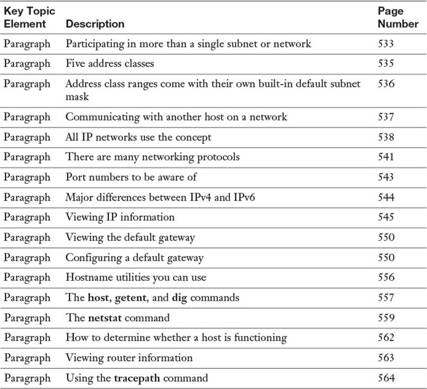
Table 19-2 Key Topics for Chapter 19
Define Key Terms
Define the following key terms from this chapter and check your answers in the glossary:
IP address
network mask
gateway
IPv4
IPv6
octet
dotted quad notation
subnetting
address class ranges
RFC
broadcast address
IP
TCP
UDP
ICMP
port
autoconfiguration
DHCP
DNS
default gateway
Review Questions
The answers to these review questions are in Appendix A.
1. If your IP is 192.168.33.35 and your network mask is /28, what is the address of your local network?
a. 192.168.33.16
b. 192.168.33.32
c. 192.168.33.0
d. 192.168.33.64
2. You need to view a user’s routing information on his workstation. Which command, with any needed options, would you use to accomplish this?
_________________________________________________________
3. Your boss wants you to create a subnet scheme that gives your company eight networks with at least 10 hosts per network. Which subnet mask for a Class C leased network address meets those objectives?
a. 255.255.255.192
b. 255.255.255.224
c. 255.255.255.240
d. 255.255.255.248
4. A user complains that she can’t reach a web mail site she frequents, but she can reach other hosts on your networks and on the Internet. Which command would show you where the problem is occurring? Fill in the blank with just the most appropriate command name:
_________________________________________________________
5. You are configuring a system and need to set your eth0 interface to have a default gateway with the address 192.168.33.1. Fill in the blank with the exact command and options to accomplish this from the command line:
_________________________________________________________
6. You want to find the mail servers for a particular domain but not see all the address records. Which of the following commands can accomplish this? (Choose all that apply.)
a. digger
b. host
c. resolver
d. dig
7. On a Red Hat machine, you need to edit a file that sets the order for how names are resolved. Fill in the blank with the full path and filename for this file:
_________________________________________________________
8. Which of the following is a valid entry for resolution methods on the hosts: line in the /etc/nsswitch.conf file? (Choose all that apply.)
a. files
b. ylwpage
c. dns
d. nis
9. You need to capture data packets from the network for later analysis. Fill in the blank with only the command name that will accomplish this on a default machine:
_________________________________________________________
All materials on the site are licensed Creative Commons Attribution-Sharealike 3.0 Unported CC BY-SA 3.0 & GNU Free Documentation License (GFDL)
If you are the copyright holder of any material contained on our site and intend to remove it, please contact our site administrator for approval.
© 2016-2026 All site design rights belong to S.Y.A.