Linux Kernel Networking: Implementation and Theory (2014)
CHAPTER 12. Wireless in Linux
Chapter 11 deals with Layer 4 protocols, which enable us to communicate with userspace. This chapter deals with the wireless stack in the Linux kernel. I describe the Linux wireless stack (mac80211 subsystem) and discuss some implementation details of important mechanisms in it, such as packet aggregation and block acknowledgement, used in IEEE 802.11n, and power save mode. Becoming familiar with the 802.11 MAC header is essential in order to understand the wireless subsystem implementation. The 802.11 MAC header, its members, and their usage are described in depth in this chapter. I also discuss some common wireless topologies, like infrastructure BSS, independent BSS, and Mesh networking.
Mac80211 Subsystem
At the end of the 1990s, there were discussions in IEEE regarding a protocol for wireless local area networks (WLANS). The original version of the IEEE 802.11 spec for WLANS was released in 1997 and revised in 1999. In the following years, some extensions were added, formally termed 802.11 amendments. These extensions can be divided into PHY (Physical) layer extensions, MAC (Medium Access Control) layer extensions, Regulatory extensions, and others. PHY layer extensions are, for example, 802.11b from 1999, 802.11a (also from 1999), and 802.11g from 2003. MAC layer extensions are, for example, 802.11e for QoS and 802.11s for Mesh networking. The “Mesh Networking” section of this chapter deals with the Linux kernel implementation of the IEEE802.11s amendment. The IEEE802.11 spec was revised, and in 2007 a second version of 1,232 pages was released. In 2012, a spec of 2,793 pages was released, available from http://standards.ieee.org/findstds/standard/802.11-2012.html. I refer to this spec as IEEE 802.11-2012 in this chapter. Following is a partial list of important 802.11 amendments:
· IEEE 802.11d: International (country-to-country) roaming extensions (2001).
· IEEE 802.11e: Enhancements: QoS, including packet bursting (2005).
· IEEE 802.11h: Spectrum Managed 802.11a for European compatibility (2004).
· IEEE 802.11i: Enhanced security (2004).
· IEEE 802.11j: Extensions for Japan (2004).
· IEEE 802.11k: Radio resource measurement enhancements (2008).
· IEEE 802.11n: Higher throughput improvements using MIMO (multiple input, multiple output antennas) (2009).
· IEEE 802.11p: WAVE: Wireless Access for the Vehicular Environment (such as ambulances and passenger cars). It has some peculiarities such as not using the BSS concept and narrower (5/10 MHz) channels. Note that IEEE 802.11p isn’t supported in Linux as of this writing.
· IEEE 802.11v: Wireless network management.
· IEEE 802.11w: Protected Management Frames.
· IEEE 802.11y: 3650–3700 MHz operation in the U.S. (2008)
· IEEE 802.11z: Extensions to Direct Link Setup (DLS) (Aug 2007–Dec 2011).
It was only in about 2001, about four years after the IEEE 802.11 first spec was approved, that laptops became very popular; many of these laptops were sold with wireless network interfaces. Today every laptop includes WiFi as standard equipment. It was important to the Linux community at that time to provide Linux drivers to these wireless network interfaces and to provide a Linux network wireless stack, in order to stay competitive with other OSes (such as Windows, Mac OS, and others). Less effort has been done regarding architecture and design. “They just want their hardware to work,” as Jeff Garzik, the Linux Kernel Wireless maintainer at that time, put it. When the first wireless drivers for Linux were developed, there was no general wireless API. As a result, there were many cases of duplication of code between drivers, when developers implemented their drivers from scratch. Some drivers were based on FullMAC, which means that most of the management layer (MLME)is managed in hardware. In the years since, a new 802.11 wireless stack called mac80211 was developed. It was integrated into the Linux kernel in July 2007, for the 2.6.22 Linux kernel. The mac80211 stack is based on the d80211 stack, which is an open source, GPL-licensed stack by a company named Devicescape.
I cannot delve into the details of the PHY layer, because that subject is very wide and deserves a book of its own. However, I must note that there are many differences between 802.11 and 802.3 wired Ethernet. Here are two major differences:
· Ethernet works with CSMA/CD, whereas 802.11 works with CSMA/CA. CSMA/CA stands for carrier sense multiple access/collision avoidance, and CSMA/CD stands for carrier sense multiple access/collision detection. The difference, as you might guess, is the collision detection. With Ethernet, a station starts to transmit when the medium is idle; if a collision is detected during transmission, it stops, and a random backoff period starts. Wireless stations cannot detect collisions while transmitting, whereas wired stations can. With CSMA/CA, the wireless station waits for a free medium and only then transmits the frame. In case of a collision, the station will not notice it, but because no acknowledgment frame should be sent for this packet, it is retransmitted after a timeout has elapsed if an acknowledgment is not received.
· Wireless traffic is sensitive to interferences. As a result, the 802.11 spec requires that every frame, except for broadcast and multicast, be acknowledged when it is received. Packets that are not acknowledged in time should be retransmitted. Note that since IEEE 802.11e, there is a mode which does not require acknowledgement—the QoSNoAck mode—but it’s rarely used in practice.
The 802.11 MAC Header
Each MAC frame consists of a MAC header, a frame body of variable length, and an FCS (Frame Check Sequence) of 32 bit CRC. Figure 12-1 shows the 802.11 header.

Figure 12-1. IEEE 802.11 header. Note that all members are not always used, as this section will shortly explain
The 802.11 header is represented in mac80211 by the ieee80211_hdr structure:
struct ieee80211_hdr {
__le16 frame_control;
__le16 duration_id;
u8 addr1[6];
u8 addr2[6];
u8 addr3[6];
__le16 seq_ctrl;
u8 addr4[6];
} __packed;
(include/linux/ieee80211.h)
In contrast to an Ethernet header (struct ethhdr), which contains only three fields (source MAC address, destination MAC address, and Ethertype), the 802.11 header contains up to six addresses and some other fields. For a typical data frame, though, only three addresses are used (for example, Access Point or AP/client communication). With an ACK frame, only the receiver address is used. Note that Figure 12-1 shows only four addresses, but when working with Mesh networking, a Mesh extension header with two additional addresses is used.
I now turn to a description of the 802.11 header fields, starting with the first field in the 802.11 header, called the frame control. This is an important field, and in many cases its contents determine the meaning of other fields of the 802.11 MAC header (especially addresses).
The Frame Control
The frame control length is 16 bits. Figure 12-2 shows its fields and the size of each field.
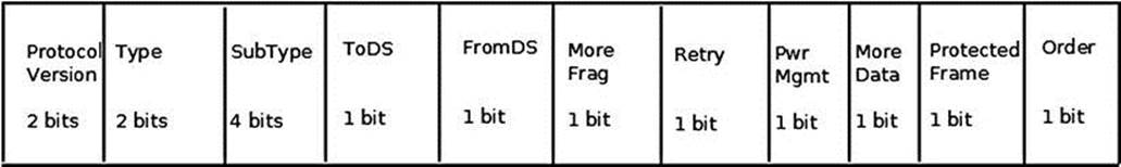
Figure 12-2. Frame control fields
The following is a description of the frame control members:
· Protocol version: The version of the MAC 802.11 we use. Currently there is only one version of MAC, so this field is always 0.
· Type: There are three types of packets in 802.11—management, control, and data:
· Management packets (IEEE80211_FTYPE_MGMT) are for management actions like association, authentication, scanning, and more.
· Control packets (IEEE80211_FTYPE_CTL) usually have some relevance to data packets; for example, a PS-Poll packet is for retrieving packets from an AP buffer. Another example: a station that wants to transmit first sends a control packet named RTS (request to send); if the medium is free, the destination station will send back a control packet named CTS (clear to send).
· Data packets (IEEE80211_FTYPE_DATA) are the raw data packets. Null packets are a special case of raw packets, carrying no data and used mostly for power management control purposes. I discuss null packets in the “Power Save Mode” section later in this chapter.
· Subtype: For all the aforementioned three types of packets (management, control, and data), there is a sub-type field which identifies the character of the packet used. For example:
· A value of 0100 for the sub-type field in a management frame denotes that the packet is a Probe Request (IEEE80211_STYPE_PROBE_REQ) management packet, which is used in a scan operation.
· A value of 1011 for the sub-type field in a control packet denotes that this is a request to send (IEEE80211_STYPE_RTS) control packet. A value of 0100 for the sub-type field of a data packet denotes that this is a null data (IEEE80211_STYPE_NULLFUNC) packet, which is used for power management control.
· A value of 1000 (IEEE80211_STYPE_QOS_DATA) for the sub-type of a data packet means that this is a QoS data packet; this sub-type was added by the IEEE802.11e amendment, which dealt with QoS enhancements.
· ToDS: When this bit is set, it means the packet is for the distribution system.
· FromDS: When this bit is set, it means the packet is from the distribution system.
· More Frag: When you use fragmentation, this bit is set to 1.
· Retry: When a packet is retransmitted, this bit is set to 1. A typical case of retransmission is when a packet that was sent did not receive an acknowledgment in time. The acknowledgments are usually sent by the firmware of the wireless driver.
· Pwr Mgmt: When the power management bit is set, it means that the station will enter power save mode. I discuss power save mode in the “Power Save Mode” section later in this chapter.
· More Data: When an AP sends packets that it buffered for a sleeping station, it sets the More Data bit to 1 when the buffer is not empty. Thus the station knows that there are more packets it should retrieve. When the buffer has been emptied, this bit is set to 0.
· Protected Frame: This bit is set to 1 when the frame body is encrypted; only data frames and authentication frames can be encrypted.
· Order: With the MAC service called strict ordering, the order of frames is important. When this service is in use, the order bit is set to 1. It is rarely used.
![]() Note The action frame (IEEE80211_STYPE_ACTION) was introduced with the 802.11h amendment, which dealt with spectrum and transmit power management. However, because of a lack of space for management packets sub-types, action frames are used also in various newer amendments to the standard—for example, HT action frames in 802.11n.
Note The action frame (IEEE80211_STYPE_ACTION) was introduced with the 802.11h amendment, which dealt with spectrum and transmit power management. However, because of a lack of space for management packets sub-types, action frames are used also in various newer amendments to the standard—for example, HT action frames in 802.11n.
The Other 802.11 MAC Header Members
The following describes the other members of the mac802.11 header, after the frame control:
· Duration/ID: The duration holds values for the Network Allocation Vector (NAV) in microseconds, and it consists of 15 bits of the Duration/ID field. The sixteenth field is 0. When working in power save mode, it is the AID (association id) of a station for PS-Poll frames (see 8.2.4.2 (a) in IEEE 802.11-2012). The Network Allocation Vector (NAV) is a virtual carrier sensing mechanism. I do not delve into NAV internals because that is beyond the scope of this chapter.
· Sequence Control: This is a 2-byte field specifying the sequence control. In 802.11, it is possible that a packet will be received more than once, most commonly when an acknowledgment is not received for some reason. The sequence control field consists of a fragment number (4 bits) and a sequence number (12 bits). The sequence number is generated by the transmitting station, in the ieee80211_tx_h_sequence() method. In the case of a duplicate frame in a retransmission, it is dropped, and a counter of the dropped duplicate frames (dot11FrameDuplicateCount) is incremented by 1; this is done in the ieee80211_rx_h_check() method. The Sequence Control field is not present in control packets.
· Address1 – Address4: There are four addresses, but you don’t always use all of them. Address 1 is the Receive Address (RA), and is used in all packets. Address 2 is the Transmit Address (TA), and it exists in all packets except ACK and CTS packets. Address 3 is used only for management and data packets. Address 4 is used when ToDS and FromDS bits of the frame control are set; this happens when operating in a Wireless Distribution System.
· QoS Control: The QoS control field was added by the 802.11e amendment and is only present in QoS data packets. Because it is not part of the original 802.11 spec, it is not part of the original mac80211 implementation, so it is not a member of the IEEE802.11 header (ieee80211_hdr struct). In fact, it was added at the end of the IEEE802.11 header and can be accessed by the ieee80211_get_qos_ctl() method. The QoS control field includes the tid (Traffic Identification), the ACK Policy, and a field called A-MSDU present, which tells whether an A-MSDU is present. I discuss A-MSDU later in this chapter, in the “High Throughput (ieee802.11n)” section.
· HT Control Field: HT (high throughput) control field was added by the 802.11n amendment (see 7.1.3.5(a) of the 802.11n-2009 spec).
This section covered the 802.11 MAC header, with a description of its members and their use. Becoming familiar with the 802.11 MAC header is essential for understanding the mac802.11 stack.
Network Topologies
There are two popular network topologies in 802.11 wireless networks. The first topology I discuss is Infrastructure BSS mode, which is the most popular. You encounter Infrastructure BSS wireless networks in home wireless networks and offices. Later I discuss the IBSS (Ad Hoc) mode. Note that IBSS is not Infrastructure BSS; IBSS is Independent BSS, which is an ad hoc network, discussed later in this section.
Infrastructure BSS
When working in Infrastructure BSS mode, there is a central device, called an Access Point (AP), and some client stations. Together they form a BSS (Basic Service Set). These client stations must first perform association and authentication against the AP to be able to transmit packets via the AP. On many occasions, client stations perform scanning prior to authentication and association, in order to get details about the AP. Association is exclusive: a client can be associated with only one AP in a given moment. When a client associates with an AP successfully, it gets an AID (association id), which is a unique number (to this BSS) in the range 1–2007. An AP is in fact a wireless network device with some hardware additions (like Ethernet ports, LEDs, a button to reset to manufacturer defaults, and more). A management daemon runs on the AP device. An example of such software is the hostapd daemon. This software handles some of the management tasks of the MLME layer, such as authentication and association requests. It achieves this by registering itself to receive the relevant management frames via nl80211. The hostapd project is an open source project which enables several wireless network devices to operate as an AP.
Clients can communicate with other clients (or to stations in a different network which is bridged to the AP) by sending packets to the AP, which are relayed by the AP to their final destination. To cover a large area, you can deploy multiple APs and connect them by wire. This type of deployment is called Extended Service Set (ESS). Within ESS deployment, there are two or more BSSs. Multicasts and broadcasts sent in one BSS, which may arrive on a nearby BSS, are rejected in the nearby BSS stations (the bssid in the 802.11 header does not match). Within such a deployment, each AP usually uses a different channel to minimize interference.
IBSS, or Ad Hoc Mode
IBSS network is often formed without preplanning, for only as long as the WLAN is needed. An IBSS network is also called ad hoc network. Creating an IBSS is a simple procedure. You can set an IBSS by running from a command line this iw command (note that the 2412 parameter is for using channel 1):
iw wlan0 ibss join AdHocNetworkName 2412
Or when using the iwconfig tool, with these two commands:
iwconfig wlan0 mode ad-hoc
iwconfig wlan0 essid AdHocNetworkrName
This triggers IBSS creation by calling the ieee80211_sta_create_ibss() method (net/mac80211/ibss.c). Then the ssid (AdHocNetworkName in this case) has to be distributed manually (or otherwise) to everyone who wants to connect to the ad hoc network. When working with IBSS, you do not have an AP. The bssid of the IBSS is a random 48-bit address (based on calling the get_random_bytes() method). Power management in Ad Hoc mode is a bit more complex than power management in Infrastructure BSS; it uses Announcement Traffic Indication Map (ATIM) messages. ATIM is not supported by mac802.11 and is not discussed in this chapter.
The next section describes power save mode, which is one of the most important mechanisms of the mac80211 network stack.
Power Save Mode
Apart from relaying packets, there is another important function for the AP: buffering packets for client stations that enter power save mode. Clients are usually battery-powered devices. From time to time, the wireless network interface enters power save mode.
Entering Power Save Mode
When a client station enters power save mode, it informs the AP about it by sending usually a null data packet. In fact, technically speaking, it does not have to be a null data packet; it is enough that it is a packet with PM=1 (PM is the Power Management flag in the frame control). An AP that gets such a null packet starts keeping unicast packets which are destined to that station in a special buffer called ps_tx_buf; there is such a buffer for every station. This buffer is in fact a linked list of packets, and it can hold up to 128 packets (STA_MAX_TX_BUFFER) for each station. If the buffer is filled, it will start discarding the packets that were received first (FIFO). Apart from this, there is a single buffer called bc_buf, for multicast and broadcast packets (in the 802.11 stack, multicast packets should be received and processed by all the stations in the same BSS). The bc_buf buffer can also hold up to 128 packets (AP_MAX_BC_BUFFER). When a wireless network interface is in power save mode, it cannot receive or send packets.
Exiting Power Save Mode
From time to time, an associated station is awakened by itself (by some timer); it then checks for special management packets, called beacons, which the AP sends periodically. Typically, an AP sends 10 beacons in a second; on most APs, this is a configurable parameter. These beacons contain data in information elements, which constitute the data in the management packet. The station that awoke checks a specific information element called TIM (Traffic Indication Map), by calling the ieee80211_check_tim() method (include/linux/ieee80211.h). The TIM is an array of 2008 entries. Because the TIM size is 251 bytes (2008 bits), you are allowed to send a partial virtual bitmap, which is smaller in size. If the entry in the TIM for that station is set, it means that the AP saved unicast packets for this station, so that station should empty the buffer of packets that the AP kept for it. The station starts sending null packets (or, more rarely, special control packets, called PS-Poll packets) to retrieve these buffered packets from the AP. Usually after the buffer has been emptied, the station goes to sleep (however, this is not mandatory according to the spec).
Handling the Multicast/Broadcast Buffer
The AP buffers multicast and broadcast packets whenever at least one station is in sleeping mode. The AID for multicast/broadcast stations is 0; so, in such a case, you set TIM[0] to true. The Delivery Team (DTIM), which is a special type of TIM, is sent not in every beacon, but once for a predefined number of beacon intervals (the DTIM period). After a DTIM is sent, the AP sends its buffered broadcast and multicast packets. You retrieve packets from the multicast/broadcast buffer (bc_buf) by calling the ieee80211_get_buffered_bc() method. In Figure 12-3 you can see an AP that contains a linked list of stations (sta_info objects), each of them with a unicast buffer (ps_tx_buf) of its own, and a single bc_buf buffer, for storing multicast and broadcast packets.
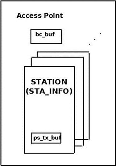
Figure 12-3. Buffering packets in an AP
The AP is implemented as an ieee80211_if_ap object in mac80211. Each such ieee80211_if_ap object has a member called ps (an instance of ps_data), where power save data is stored. One of the members of the ps_data structure is the broadcast/multicast buffer,bc_buf.
In Figure 12-4 you can see a flow of PS-Poll packets that a client sends in order to retrieve packets from the AP unicast buffer, ps_tx_buf. Note that the AP sends all the packets with the IEEE80211_FCTL_MOREDATA flag, except for the last one. Thus, the client knows that it should keep on sending PS-Poll packets until the buffer is emptied. For the sake of simplicity, the ACK traffic in this diagram is not included, but it should be mentioned here that the packets should be acknowledged.
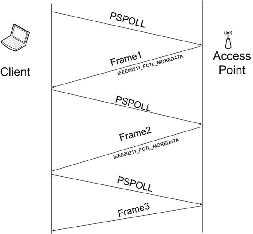
Figure 12-4. Sending PSPOLL packets from a client to retrieve packets from the ps_tx_buf buffer within an AP
![]() Note Power management and power save mode are two different topics. Power management deals with handling machines that perform suspend (whether it is suspend to RAM or suspend to disk, aka hibernate, or in some cases, both suspend to RAM and suspend to disk, aka hybrid suspend), and is handled in net/mac80211/pm.c. In the drivers, power management is handled by the resume/suspend methods. Power save mode, on the other hand, deals with handling stations that enter sleep mode and wake up; it has nothing to do with suspend and hibernation.
Note Power management and power save mode are two different topics. Power management deals with handling machines that perform suspend (whether it is suspend to RAM or suspend to disk, aka hibernate, or in some cases, both suspend to RAM and suspend to disk, aka hybrid suspend), and is handled in net/mac80211/pm.c. In the drivers, power management is handled by the resume/suspend methods. Power save mode, on the other hand, deals with handling stations that enter sleep mode and wake up; it has nothing to do with suspend and hibernation.
This section described power save mode and the buffering mechanism. The next section discusses the management layer and the different tasks it handles.
The Management Layer (MLME)
There are three components in the 802.11 management architecture:
· The Physical Layer Management Entity (PLME).
· The System Management Entity (SME).
· The MAC Layer Management Entity (MLME).
Scanning
There are two types of scanning: passive scanning and active scanning. Passive scanning means to listen passively for beacons, without transmitting any packets for scanning. When performing passive scanning (the flags of the scan channel contain IEEE80211_CHAN_PASSIVE_SCAN), the station moves from channel to channel, trying to receive beacons. Passive scanning is needed in some higher 802.11a frequency bands, because you’re not allowed to transmit anything at all until you’ve heard an AP beacon. With active scanning, each station sends a Probe Request packet; this is a management packet, with sub-type Probe Request (IEEE80211_STYPE_PROBE_REQ). Also with active scanning, the station moves from channel to channel, sending a Probe Request management packet on each channel (by calling the ieee80211_send_probe_req()method). This is done by calling the ieee80211_request_scan() method. Changing channels is done via a call to the ieee80211_hw_config() method, passing IEEE80211_CONF_CHANGE_CHANNEL as a parameter. Note that there is a one-to-one correspondence between a channel in which a station operates and the frequency in which it operates; the ieee80211_channel_to_frequency() method (net/wireless/util.c) returns the frequency in which a station operates, given its channel.
Authentication
Authentication is done by calling the ieee80211_send_auth() method (net/mac80211/util.c). It sends a management frame with authentication sub-type (IEEE80211_STYPE_AUTH). There are many authentications types; the original IEEE802.11 spec talked about only two forms: open-system authentication and shared key authentication. The only mandatory authentication method required by the IEEE802.11 spec is the open-system authentication (WLAN_AUTH_OPEN). This is a very simple authentication algorithm—in fact, it is a null authentication algorithm. Any client that requests authentication with this algorithm will become authenticated. An example of another option for an authentication algorithm is the shared key authentication (WLAN_AUTH_SHARED_KEY). In shared key authentication, the station should authenticate using a Wired Equivalent Privacy (WEP) key.
Association
In order to associate, a station sends a management frame with association sub-type (IEEE80211_STYPE_ASSOC_REQ). Association is done by calling the ieee80211_send_assoc() method (net/mac80211/mlme.c).
Reassociation
When a station moves between APs within an ESS, it is said to be roaming. The roaming station sends a reassociation request to a new AP by sending a management frame with reassociation sub-type (IEEE80211_STYPE_REASSOC_REQ). Reassociation is done by calling theieee80211_send_assoc() method; there are many similarities between association and reassociation, so this method handles both. In addition, with reassociation, the AP returns an AID (association id) to the client in case of success.
This section talked about the management layer (MLME) and some of the operations it supports, like scanning, authentication, association, and more. In the next section I describe some mac80211 implementation details that are important in order to understand the wireless stack.
Mac80211 Implementation
Mac80211 has an API for interfacing with the low level device drivers. The implementation of mac80211 is complex and full of many small details. I cannot give an exhaustive description of the mac80211 API and implementation; I do discuss some important points that can give a good starting point to those who want to delve into the code. A fundamental structure of mac80211 API is the ieee80211_hw struct (include/net/mac80211.h); it represents hardware information. The priv (pointer to a private area) pointer of ieee80211_hw is of an opaque type (void *). Most wireless device drivers define a private structure for this private area, like lbtf_private (Marvell wireless driver) or iwl_priv (iwlwifi from Intel). Memory allocation and initialziation for the ieee80211_hw struct is done by theieee80211_alloc_hw() method. Here are some methods related to the ieee80211_hw struct:
· int ieee80211_register_hw(struct ieee80211_hw *hw): Called by wireless drivers for registering the specified ieee80211_hw object.
· void ieee80211_unregister_hw(struct ieee80211_hw *hw): Unregisters the specified 802.11 hardware device.
· struct ieee80211_hw *ieee80211_alloc_hw(size_t priv_data_len, const struct ieee80211_ops *ops): Allocates an ieee80211_hw object and initializes it.
· ieee80211_rx_irqsafe(): This method is for receiving a packet. It is implemented in net/mac80211/rx.c and called from low level wireless drivers.
The ieee80211_ops object, which is passed to the ieee80211_alloc_hw() method as you saw earlier, consists of pointers to callbacks to the driver. Not all of these callbacks must be implemented by the drivers. The following is a short description of these methods:
· tx(): The transmit handler called for each transmitted packet. It usually returns NETDEV_TX_OK (except for under certain limited conditions).
· start(): Activates the hardware device and is called before the first hardware device is enabled. It turns on frame reception.
· stop(): Turns off frame reception and usually turns off the hardware.
· add_interface(): Called when a network device attached to the hardware is enabled.
· remove_interface(): Informs a driver that the interface is going down.
· config(): Handles configuration requests, such as hardware channel configuration.
· configure_filter(): Configures the device’s Rx filter.
Figure 12-5 shows a block diagram of the architecture of the Linux wireless subsystem. You can see that the interface between wireless device drivers layer and the mac80211 layer is the ieee80211_ops object and its callbacks.
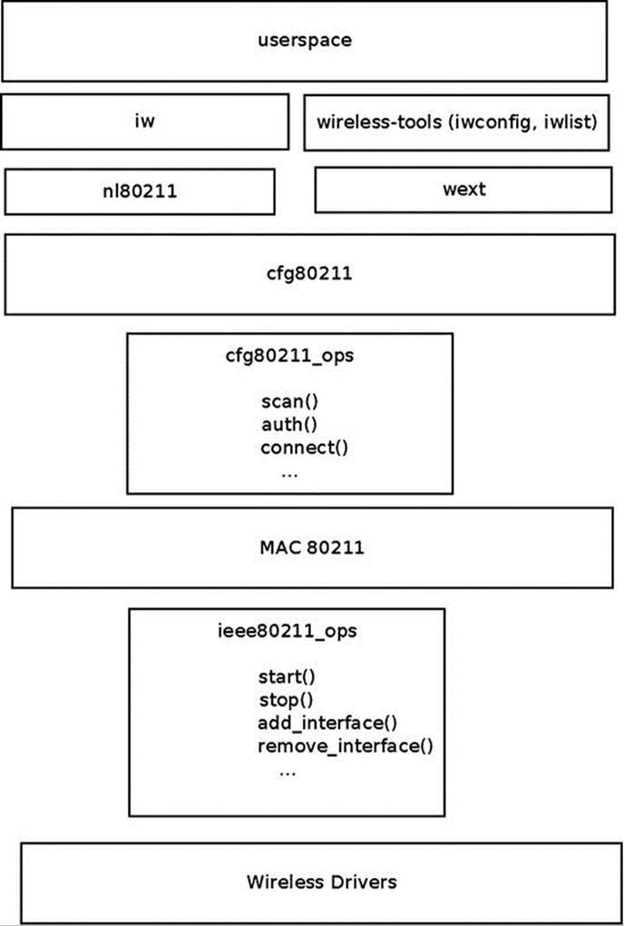
Figure 12-5. Linux wireless architecture
Another important structure is the sta_info struct (net/mac80211/sta_info.h), which represents a station. Among the members of this structure are various statistics counters, various flags, debugfs entries, the ps_tx_buf array for buffering unicast packets, and more. Stations are organized in a hash table (sta_hash) and a list (sta_list). The important methods related to sta_info are as follows:
· int sta_info_insert(struct sta_info *sta): Adds a station.
· int sta_info_destroy_addr(struct ieee80211_sub_if_data *sdata, const u8 *addr): Removes a station (by calling the __sta_info_destroy() method).
· struct sta_info *sta_info_get(struct ieee80211_sub_if_data *sdata, const u8 *addr): Fetches a station; the address of the station (it’s bssid) is passed as a parameter.
Rx Path
The ieee80211_rx() function (net/mac80211/rx.c) is the main receive handler. The status of the received packet (ieee80211_rx_status) is passed by the wireless driver to mac80211, embedded in the SKB control buffer (cb). The IEEE80211_SKB_RXCB() macro is used to fetch this status. The flag field of the Rx status specifies, for example, whether the FCS check failed on the packet (RX_FLAG_FAILED_FCS_CRC). The various values possible for the flag field are presented in Table 12-1 in the “Quick Reference” section of this chapter. In theieee80211_rx() method, the ieee80211_rx_monitor() is invoked to remove the FCS (checksum) and remove a radiotap header (struct ieee80211_radiotap_header) which might have been added if the wireless interface is in monitor mode. (You use a network interface in monitor mode in case of sniffing, for example. Not all the wireless network interfaces support monitor mode, see the section “Wireless Modes” later in this chapter.)
If you work with HT (802.11n), you perform AMPDU reordering if needed by invoking the ieee80211_rx_reorder_ampdu() method. Then you call the __ieee80211_rx_handle_packet() method, which eventually calls the ieee80211_invoke_rx_handlers()method. Then you call, one by one, various receive handlers (using a macro named CALL_RXH). The order of calling these handlers is important. Each handler checks whether it should handle the packet or not. If it decides it should not handle the packet, then you return RX_CONTINUE and proceed to the next handler. If it decides it should handle the packet, then you return RX_QUEUED.
There are certain cases when a handler decides to drop a packet; in these cases, it returns RX_DROP_MONITOR or RX_DROP_UNUSABLE. For example, if you get a PS-Poll packet, and the type of the receiver shows that it is not an AP, you return RX_DROP_UNUSABLE. Another example: for a management frame, if the length of the SKB is less than the minimum (24), the packet is discarded and RX_DROP_MONITOR is returned. Or if the packet is not a management packet, then also the packet is discarded and RX_DROP_MONITOR is returned. Here is the code snippet from the ieee80211_rx_h_mgmt_check() method that implements this:
ieee80211_rx_h_mgmt_check(struct ieee80211_rx_data *rx)
{
struct ieee80211_mgmt *mgmt = (struct ieee80211_mgmt *) rx->skb->data;
struct ieee80211_rx_status *status = IEEE80211_SKB_RXCB(rx->skb);
. . .
if (rx->skb->len < 24)
return RX_DROP_MONITOR;
if (!ieee80211_is_mgmt(mgmt->frame_control))
return RX_DROP_MONITOR;
. . .
}
(net/mac80211/rx.c)
Tx Path
The ieee80211_tx() method is the main handler for transmission (net/mac80211/tx.c). First it invokes the __ieee80211_tx_prepare() method, which performs some checks and sets certain flags. Then it calls the invoke_tx_handlers() method, which calls, one by one, various transmit handlers (using a macro named CALL_TXH). If a transmit handler finds that it should do nothing with the packet, it returns TX_CONTINUE and you proceed to the next handler. If it decides it should handle a certain packet, it returns TX_QUEUED, and if it decides it should drop the packet, it returns TX_DROP. The invoke_tx_handlers() method returns 0 upon success. Let’s take a short look in the implementation of the ieee80211_tx() method:
static bool ieee80211_tx(struct ieee80211_sub_if_data *sdata,
struct sk_buff *skb, bool txpending,
enum ieee80211_band band)
{
struct ieee80211_local *local = sdata->local;
struct ieee80211_tx_data tx;
ieee80211_tx_result res_prepare;
struct ieee80211_tx_info *info = IEEE80211_SKB_CB(skb);
bool result = true;
int led_len;
Perform a sanity check, drop the SKB if its length is less than 10:
if (unlikely(skb->len < 10)) {
dev_kfree_skb(skb);
return true;
}
/* initialises tx */
led_len = skb->len;
res_prepare = ieee80211_tx_prepare(sdata, &tx, skb);
if (unlikely(res_prepare == TX_DROP)) {
ieee80211_free_txskb(&local->hw, skb);
return true;
} else if (unlikely(res_prepare == TX_QUEUED)) {
return true;
}
Invoke the Tx handlers; if everything is fine, continue with invoking the __ieee80211_tx() method:
. . .
if (!invoke_tx_handlers(&tx))
result = __ieee80211_tx(local, &tx.skbs, led_len,
tx.sta, txpending);
return result;
}
(net/mac80211/tx.c)
Fragmentation
Fragmentation in 802.11 is done only for unicast packets. Each station is assigned a fragmentation threshold size (in bytes). Packets that are bigger than this threshold should be fragmented. You can lower the number of collisions by reducing the fragmentation threshold size, making the packets smaller. You can inspect the fragmentation threshold of a station by running iwconfig or by inspecting the corresponding debugfs entry (see the “Mac80211 debugfs” section later in this chapter). You can set the fragmentation threshold with the iwconfig command; thus, for example, you can set the fragmentation threshold to 512 bytes by:
iwconfig wlan0 frag 512
Each fragment is acknowledged. The more fragment field in the fragment header is set to 1 if there are more fragments. Each fragment has a fragment number (a subfield in the sequence control field of the frame control). Reassembling of the fragments on the receiver is done according to the fragments numbers. Fragmentation in the transmitter side is done by the ieee80211_tx_h_fragment() method (net/mac80211/tx.c). Reassembly on the receiver side is done by the ieee80211_rx_h_defragment() method (net/mac80211/rx.c). Fragmentation is incompatible with aggregation (used for higher throughput), and given the high rates and thus short (in time) packets it is very rarely used nowadays.
Mac80211 debugfs
debugfsis a technique that enables exporting debugging information to userspace. It creates entries under the sysfs filesystem. debugfs is a virtual filesystem devoted to debugging information. For mac80211, handling mac80211 debugfs is mostly innet/mac80211/debugfs.c. After mounting debugfs, various mac802.11 statistics and information entries can be inspected. Mounting debugfs is performed like this:
mount -t debugfs none_debugs /sys/kernel/debug
![]() Note CONFIG_DEBUG_FS must be set when building the kernel to be able to mount and work with debugfs.
Note CONFIG_DEBUG_FS must be set when building the kernel to be able to mount and work with debugfs.
For example, let’s say your phy is phy0; the following is a discussion about some of the entries under /sys/kernel/debug/ieee80211/phy0:
· total_ps_buffered: This is the total number of packets (unicast and multicasts/broadcasts) which the AP buffered for the station. The total_ps_buffered counter is incremented by ieee80211_tx_h_unicast_ps_buf() for unicasts, and byieee80211_tx_h_multicast_ps_buf() for multicasts or broadcasts.
· Under /sys/kernel/debug/ieee80211/phy0/statistics, you have various statistical information—for example:
· frame_duplicate_count denotes the number of duplicate frames. This debugfs entry represents the duplicate frames counter, dot11FrameDuplicateCount, which is incremented by the ieee80211_rx_h_check() method.
· transmitted_frame_count denotes the number of transmitted packets. This debugfs entry represents dot11TransmittedFrameCount; it is incremented by the ieee80211_tx_status() method.
· retry_count denotes number of retransmissions. This debugfs entry represents dot11RetryCount; it is incremented also by the ieee80211_tx_status() method.
· fragmentation_threshold: The size of the fragmentation threshold, in bytes. See the “Fragmentation” section earlier.
· Under /sys/kernel/debug/ieee80211/phy0/netdev:wlan0, you have some entries that give information about the interface; for example, if the interface is in station mode, you will have aid for the association id of the station, assoc_tries for the number of times the stations tried to perform association, bssid is for the bssid of the station, and so on.
· Every station uses a rate control algorithm. Its name is exported by the following debugfs entry: /sys/kernel/debug/ieee80211/phy1/rc/name.
Wireless Modes
You can set a wireless network interface to operate in several modes, depending on its intended use and the topology of the network in which it is deployed. In some cases, you can set the mode with the iwconfig command, and in some cases you must use a tool like hostapd for this. Note that not all devices support all modes. See www.linuxwireless.org/en/users/Drivers for a list of Linux drivers that support different modes. Alternatively, you can also check to which values the interface_modes field of the wiphy member (in the ieee80211_hwobject) is initialized in the driver code. The interface_modes are initialized to one or more modes of the nl80211_iftype enum, like NL80211_IFTYPE_STATION or NL80211_IFTYPE_ADHOC (see: include/uapi/linux/nl80211.h). The following is a detailed description of these wireless modes:
· AP mode: In this mode, the device acts as an AP (NL80211_IFTYPE_AP). The AP maintains and manages a list of associated stations. The network (BSS) name is the MAC address of the AP (bssid). There is also a human-readable name for the BSS, called the SSID.
· Station infrastructure mode: A managed station in an infrastructure mode (NL80211_IFTYPE_STATION).
· Monitor mode:All incoming packets are handed unfiltered in monitor mode (NL80211_IFTYPE_MONITOR). This is useful for sniffing. It is usually possible to transmit packets in monitor mode. This is termed packet injection; these packets are marked with a special flag (IEEE80211_TX_CTL_INJECTED).
· Ad Hoc (IBSS) mode:A station in an ad hoc (IBSS) network (NL80211_IFTYPE_ADHOC). With Ad Hoc mode, there is no AP device in the network.
· Wireless Distribution System (WDS) mode:A station in a WDS network (NL80211_IFTYPE_WDS).
· Mesh mode:A station in a Mesh network (NL80211_IFTYPE_MESH_POINT), discussed in the “Mesh Networking (802.11s)” section later in this chapter.
The next section discusses the ieee802.11n technology, which provides higher performance, and how it is implemented in the Linux wireless stack. You will learn also about block acknowledgment and packet aggregation in 802.11n and how these techniques are used to improve performance.
High Throughput (ieee802.11n)
A little after 802.11g was approved, a new task group was created in IEEE, called High Throughput Task Group (TGn). IEEE 802.11n became a final spec at the end of 2009. The IEEE 802.11n protocol allows coexistence with legacy devices. There were some vendors who already sold 802.11n pre-standard devices based on the 802.11n draft before the official approval. Broadcom set a precedent for releasing wireless interfaces based on a draft. In 2003, it released a chipset of a wireless device based on a draft of 802.11g. Following this precedent, as early as 2005 some vendors released products based on the 802.11n draft. For example, Intel Santa Rose processor has Intel Next-Gen Wireless-N (Intel WiFI Link 5000 series), supports 802.11n. Other Intel wireless network interfaces, like 4965AGN, also supported 802.11n. Other vendors, including Atheros and Ralink, also released 802.11n draft-based wireless devices. The WiFi alliance started certification of 802.11n draft devices in June 2007. A long list of vendors released products which comply with Wi-Fi CERTIFIED 802.11n draft 2.0.
802.11n can operate on the 2.4 GHz and/or 5 GHz bands, whereas 802.11g and 802.11b operate only in the 2.4 GHz radio frequency band, and 802.11a operates only in the 5 GHz radio frequency band. The 802.11n MIMO (Multiple Input, Multiple Output) technology increases the range and reliability of traffic over the wireless coverage area. MIMO technology uses multiple transmitter and receiver antennas on both APs and clients, to allow for simultaneous data streams. The result is increased range and increased throughput. With 802.11n you can achieve a theoretical PHY rate of up to 600 Mbps (actual throughput will be much lower due to medium access rules, and so on).
802.11n added many improvements for the 802.11 MAC layer. The most well known is packet aggregation, which concatenates multiple packets of application data into a single transmission frame. A block acknowledgment (BA) mechanism was added (discussed in the next section). BA permits multiple packets to be acknowledged by a single packet instead of sending an ACK for each received packet. The wait time between two consecutive packets is cut. This enables sending multiple data packets with a fixed overhead cost of a single packet. The BA protocol was introduced in the 802.11e amendment from 2005.
Packet Aggregation
There are two types of packet aggregation:
· AMSDU: Aggregated Mac Service Data Unit
· AMPDU: Aggregated Mac Protocol Data Unit
Note that the AMSDU is only supported on Rx, and not on Tx, and is wholly independent from the Block Ack mechanism described in this section; so the discussion in this section only pertains to AMPDU.
There are two sides to a Block Ack session: originator and recipient. Each block session has a different Traffic Identifier (TID). The originator starts the block acknowledgement session by calling the ieee80211_start_tx_ba_session() method. This is done typically from a rate control algorithm method in the driver. For example, with the ath9k wireless driver, the ath_tx_status() function (drivers/net/wireless/ath/ath9k/rc.c), which is a rate control callback, invokes the ieee80211_start_tx_ba_session() method. Theieee80211_start_tx_ba_session() method sets the state to HT_ADDBA_REQUESTED_MSK and sends an ADDBA request packet, by invoking the ieee80211_send_addba_request() method. The call to ieee80211_send_addba_request() passes parameters for the session, such as the wanted reorder buffer size and the TID of the session.
The reorder buffer size is limited to 64K (see the definition of ieee80211_max_ampdu_length_exp in include/linux/ieee80211.h). These parameters are part of the capability member (capab) in the struct addba_req. The response to the ADDBA request should be received within 1 Hz, which is one second in x86_64 machines (ADDBA_RESP_INTERVAL). If you do not get a response in time, the sta_addba_resp_timer_expired() method will stop the BA session by calling the ___ieee80211_stop_tx_ba_session() method. When the other side (the recipient) receives the ADDBA request, it first sends an ACK (every packet in ieee802.11 should be acknowledged, as mentioned before). Then it processes the ADDBA request by calling the ieee80211_process_addba_request() method; if everything is okay, it sets the aggregation state of this machine to operational (HT_AGG_STATE_OPERATIONAL) and sends an ADDBA response by calling the ieee80211_send_addba_resp() method. It also stops the response timer (the timer which has as its callback thesta_addba_resp_timer_expired() method) by calling del_timer_sync()on this timer. After a session is started, a data block containing multiple MPDU packets is sent. Consequently, the originator sends a Block Ack Request (BAR) packet by calling theieee80211_send_bar() method.
Block Ack Request (BAR)
The BAR is a control packet with Block Ack Request sub-type (IEEE80211_STYPE_BACK_REQ). The BAR packet includes the SSN (start sequence number), which is the sequence number of the oldest MSDU in the block that should be acknowledged. The recipient receives the BAR and reorders the ampdu buffer accordingly, if needed. Figure 12-6 shows a BAR request.
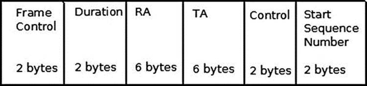
Figure 12-6. BAR request
When sending a BAR, the type subfield in the frame control is control (IEEE80211_FTYPE_CTL), and the subtype subfield is Block Ack request (IEEE80211_STYPE_BACK_REQ). The BAR is represented by the ieee80211_bar struct:
struct ieee80211_bar {
__le16 frame_control;
__le16 duration;
__u8 ra[6];
__u8 ta[6];
__le16 control;
__le16 start_seq_num;
} __packed;
(include/linux/ieee80211.h)
The RA is the recipient address, and the TA is the transmitter (originator) address. The control field of the BAR request includes the TID.
Block Ack
There are two types of Block Ack: Immediate Block Ack and Delayed Block Ack. Figure 12-7 shows Immediate Block Ack.
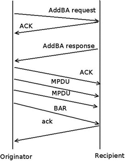
Figure 12-7. Immediate Block Ack
The difference between Immediate Block Ack and Delayed Block Ack is that with Delayed Block Ack, the BAR request itself is answered first with an ACK, and then after some delay, with a BA (Block Ack). When using Delayed Block Ack, there is more time to process the BAR, and this is sometime needed when working with software based processing. Using Immediate Block Ack is better in terms of performance. The BA itself is also acknowledged. When the originator has no more data to send, it can terminate the Block Ack session by calling theieee80211_send_delba() method; this function sends a DELBA request packet to the other side. The DELBA request is handled by the ieee80211_process_delba() method. The DELBA message, which causes a Block Ack session tear down, can be sent either from the originator or recipient of the Block Ack session. The AMPDU maximum length is 65535 octets. Note that packet aggregation is only implemented for APs and managed stations; packet aggregation for IBSS is not supported by the spec.
Mesh Networking (802.11s)
The IEEE 802.11s protocol started as a Study Group of IEEE in September 2003, and became a Task Group named TGs in 2004. In 2006, 2 proposals, out of 15 (the “SEEMesh” and “Wi-Mesh” proposals) were merged into one, which resulted in draft D0.01. 802.11s was ratified in July 2011 and is now part of IEEE 802.11-2012. Mesh networks allow the creation of an 802.11 Basic Service Set over fully and partially connected Mesh topology. This can be seen as an improvement over 802.11 ad hoc network, which requires a fully-connected Mesh topology. Figures 12-8 and 12-9illustrate the difference between the two types of Mesh topologies.
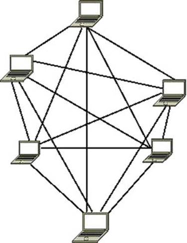
Figure 12-8. Full Mesh
In a partially-connected Mesh, nodes are connected to only some of the other nodes, but not to all of them. This topology is much more common in wireless Mesh networks. Figure 12-9 shows an example of a partial mesh.
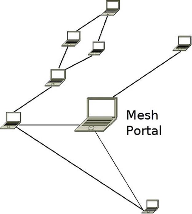
Figure 12-9. Partial Mesh
Wireless mesh networks forward data packets over multiple wireless hops. Each mesh node acts as a relay point/router for the other mesh nodes. In kernel 2.6.26 (2008), support for the draft of wireless mesh networking (802.11s) was added to the network wireless stack, thanks to the open80211s project. The open80211s project goal was to create the first open implementation of 802.11s. The project got some sponsorship from the OLPC project and from some commercial companies. Luis Carlos Cobo and Javier Cardona and other developers from Cozybit developed the Linux mac80211 Mesh code.
Now that you have learned a bit about Mesh networking and Mesh network topologies, you are ready for the next section, which covers the HWMP routing protocol for Mesh networks.
HWMP Protocol
The 802.11s protocol defines a default routing protocol called HWMP (Hybrid Wireless Mesh Protocol). The HWMP protocol works with Layer 2 and deals with MAC addresses, as opposed to the IPV4 routing protocol, for example, which works with Layer 3 and deals with IP addresses. HWMP routing is based on two types of routing (hence it is called hybrid). The first is on-demand routing, and the second is proactive routing. The main difference between the two mechanisms has to do with the time in which path establishment is initiated (path is the name used for route in Layer 2). In on-demand routing, a path to a destination is established by the protocol only after the protocol stack has received frames for such a destination. This minimizes the amount of management traffic required to maintain the Mesh network at the expense of introducing additional latency in data traffic. Proactive routing can be used if a Mesh node is known to be the recipient of a lot of mesh traffic. In that case, the node will periodically announce itself over the Mesh network and trigger path establishments to itself from all the Mesh nodes in the network. Both on-demand and proactive routing are implemented in the Linux kernel. There are four types of routing messages:
· PREQ (Path Request): This type of message is sent as a broadcast when you look for some destination that you still do not have a route to. This PREQ message is propagated in the Mesh network until it gets to its destination. A lookup is performed on each station until the final destination is reached (by calling the mesh_path_lookup() method). If the lookup fails, the PREQ is forwarded (as a broadcast) to the other stations. The PREQ message is sent in a management packet; its sub-type is action (IEEE80211_STYPE_ACTION). It is handled by the hwmp_preq_frame_process() method.
· PREP (Path Reply): This type is a unicast packet that is sent as a reply to a PREQ message. This packet is sent in the reverse path. The PREP message is also sent in a management packet and its subtype is also the action sub-type (IEEE80211_STYPE_ACTION). It is handled by the hwmp_prep_frame_process() method. Both the PREQ and the PREP messages are sent by the mesh_path_sel_frame_tx() method.
· PERR (Path Error): If there is some failure on the way, a PERR is sent. A PERR message is handled by the mesh_path_error_tx() method.
· RANN (Root Announcement): The Root Mesh point periodically broadcasts this frame. Mesh points that receive it send a unicast RREQ to the root via the MP from which it received the RANN. In response, the Root Mesh will send a PREP response to each PREQ.
![]() Note The route takes into consideration a radio-aware metric (airtime metric). The airtime metric is calculated by the airtime_link_metric_get() method (based on rate and other hardware parameters). Mesh points continuously monitor their links and update metric values with neighbours.
Note The route takes into consideration a radio-aware metric (airtime metric). The airtime metric is calculated by the airtime_link_metric_get() method (based on rate and other hardware parameters). Mesh points continuously monitor their links and update metric values with neighbours.
The station that sent the PREQ may try to send packets to the final destination while still not knowing the route to that destination; these packets are kept in a buffer of SKBs named frame_queue, which is a member of the mesh_path object (net/mac80211/mesh.h). In such a case, when a PREP finally arrives, the pending packets of this buffer are sent to the final destination (by calling the mesh_path_tx_pending() method). The maximum number of frames buffered per destination for unresolved destinations is 10 (MESH_FRAME_QUEUE_LEN). The advantages of Mesh networking are as follows:
· Rapid deployment
· Minimal configuration, inexpensive
· Easy to deploy in hard-to-wire environments
· Connectivity while nodes are in motion
· Higher reliability: no single point of failure and the ability to heal itself
The disadvantages are as follows:
· Many broadcasts limit network performance.
· Not all wireless drivers support Mesh mode at the moment.
Setting Up a Mesh Network
There are two sets of userspace tools for managing wireless devices and networks in Linux: one is the older Wireless Tools for Linux, an open source project based on IOCTLs. Examples of command line utilities of the wireless tools are iwconfig, iwlist, ifrename, and more. The newer tool is iw, based on generic netlink sockets (described in Chapter 2). However, there are some tasks that only the newer tool, iw, can perform. You can set a wireless device to work in Mesh mode only with the iw command.
Example: setting a wireless network interface (wlan0) to work in Mesh mode can be done like this:
iw wlan0 set type mesh
![]() Note Setting a wireless network interface (wlan0) to work in mesh mode can be done also like this:iw wlan0 set type mp
Note Setting a wireless network interface (wlan0) to work in mesh mode can be done also like this:iw wlan0 set type mp
mp stands for Mesh Point. See “Adding interfaces with iw” in http://wireless.kernel.org/en/users/Documentation/iw
Joining the mesh is done by: iw wlan0 mesh join "my-mesh-ID"
You can display statistics about a station by the following:
· iw wlan0 station dump
· iw wlan0 mpath dump
I should mention here also the authsae and the wpa_supplicant tools, which can be used to create secure Mesh networks and do not depend upon iw.
Linux Wireless Development Process
Most development is done using the git distributed version control system, as with many other Linux subsystems. There are three main git trees; the bleeding edge is the wireless-testing tree. There are also the regular wireless tree and the wireless-next tree. The following are the links to the git repositories for the development trees:
· wireless-testing development tree:
git://git.kernel.org/pub/scm/linux/kernel/git/linville/wireless-testing.git
· wireless development tree:
git://git.kernel.org/pub/scm/linux/kernel/git/linville/wireless-2.6.git
· wireless-next development tree:
· git://git.kernel.org/pub/scm/linux/kernel/git/linville/wireless-next-2.6.git
Patches are sent and discussed in the wireless mailing list: linux-wireless@vger.kernel.org. From time to time a pull request is sent to the kernel networking mailing list, netdev, mentioned in Chapter 1.
As mentioned in the “Mac80211 subsystem” section, which dealt with the mac80211 subsystem, some wireless network interface vendors maintain their own development trees for their Linux drivers on their own sites. In some cases, the code they are using does not use the mac80211 API; for example, some Ralink and Realtek wireless device drivers. Since January 2006, the maintainer of the Linux wireless subsystem is John W. Linville, who replaced Jeff Garzik. The maintainer of mac80211 is Johannes Berg, from October 2007. There were some annual Linux wireless summits; the first took place in 2006 in Beaverton (OR). A very detailed wiki page is here: http://wireless.kernel.org/. This web site includes a lot of important documentation. For example, a table specifies the modes each wireless network interface supports. There is a lot of information in this wiki page regarding many wireless device drivers, hardware, and various tools (such as CRDA, the central regulatory domain agent, hostapd, iw, and more).
Summary
A lot of development has been done in Linux wireless stack in recent years. The most significant change is the integration of the mac80211 stack and porting wireless drivers to use the mac80211 API, making the code much more organized. The situation is much better than before; many more wireless devices are supported in Linux. Mesh networking got a boost recently thanks to the open802.11s project. It was integrated in the Linux 2.6.26 kernel. The future will probably see more drivers that support the new standard, IEEE802.11ac, a 5 GHz-only technology that can reach maximum throughputs well above a gigabit per second, and more drivers that support P2P.
Chapter 13 discusses InfiniBand and RDMA in the Linux kernel. The “Quick Reference” section covers the top methods that are related to the topics discussed in this chapter, ordered by their context.
Quick Reference
I conclude this chapter with a short list of important methods of the Linux wireless subsystem, some of which are mentioned in this chapter. Table 12-1 shows the various possible values for the flag member of the ieee80211_rx_status object.
Methods
This section discusses the methods.
void ieee80211_send_bar(struct ieee80211_vif *vif, u8 *ra, u16 tid, u16 ssn);
This method sends a block acknowledgment request.
int ieee80211_start_tx_ba_session(struct ieee80211_sta *pubsta, u16 tid, u16 timeout);
This method starts a Block Ack session by calling the wireless driver ampdu_action() callback, passing IEEE80211_AMPDU_TX_START. As a result, the driver will later call the ieee80211_start_tx_ba_cb() callback or the ieee80211_start_tx_ba_cb_irqsafe()callback, which will start the aggregation session.
int ieee80211_stop_tx_ba_session(struct ieee80211_sta *pubsta, u16 tid);
This method stops a Block Ack session by calling the wireless driver ampdu_action() function, passing IEEE80211_AMPDU_TX_STOP. The driver must later call the ieee80211_stop_tx_ba_cb() callback or the ieee80211_stop_tx_ba_cb_irqsafe() callback.
static void ieee80211_send_addba_request(struct ieee80211_sub_if_data *sdata, const u8 *da, u16 tid, u8 dialog_token, u16 start_seq_num, u16 agg_size, u16 timeout);
This method sends an ADDBA message. An ADDBA message is a management action message.
void ieee80211_process_addba_request(struct ieee80211_local *local, struct sta_info *sta, struct ieee80211_mgmt *mgmt, size_t len);
This method handles an ADDBA message.
static void ieee80211_send_addba_resp(struct ieee80211_sub_if_data *sdata, u8 *da, u16 tid, u8 dialog_token, u16 status, u16 policy, u16 buf_size, u16 timeout);
This method sends an ADDBA response. An ADDBA response is a management packet, with subtype of action (IEEE80211_STYPE_ACTION).
static ieee80211_rx_result debug_noinline ieee80211_rx_h_amsdu(struct ieee80211_rx_data *rx);
This method handles AMSDU aggregation (Rx path).
void ieee80211_process_delba(struct ieee80211_sub_if_data *sdata, struct sta_info *sta, struct ieee80211_mgmt *mgmt, size_t len);
This method handles a DELBA message.
void ieee80211_send_delba(struct ieee80211_sub_if_data *sdata, const u8 *da, u16 tid, u16 initiator, u16 reason_code);
This method sends a DELBA message.
void ieee80211_rx_irqsafe(struct ieee80211_hw *hw, struct sk_buff *skb);
This method receives a packet. The ieee80211_rx_irqsafe() method can be called in hardware interrupt context.
static void ieee80211_rx_reorder_ampdu(struct ieee80211_rx_data *rx, struct sk_buff_head *frames);
This method handles the A-MPDU reorder buffer.
static bool ieee80211_sta_manage_reorder_buf(struct ieee80211_sub_if_data *sdata, struct tid_ampdu_rx *tid_agg_rx, struct sk_buff_head *frames);
This method handles the A-MPDU reorder buffer.
static ieee80211_rx_result debug_noinline ieee80211_rx_h_check(struct ieee80211_rx_data *rx);
This method drops duplicate frames of a retransmission and increment dot11FrameDuplicateCount and the station num_duplicates counter.
void ieee80211_send_nullfunc(struct ieee80211_local *local, struct ieee80211_sub_if_data *sdata, int powersave);
This method sends a special NULL data frame.
void ieee80211_send_pspoll(struct ieee80211_local *local, struct ieee80211_sub_if_data *sdata);
This method sends a PS-Poll control packet to an AP.
static void ieee80211_send_assoc(struct ieee80211_sub_if_data *sdata);
This method performs association or reassociation by sending a management packet with association sub-type of IEEE80211_STYPE_ASSOC_REQ or IEEE80211_STYPE_REASSOC_REQ, respectively. The ieee80211_send_assoc() method is invoked from theieee80211_do_assoc() method.
void ieee80211_send_auth(struct ieee80211_sub_if_data *sdata, u16 transaction, u16 auth_alg, u16 status, const u8 *extra, size_t extra_len, const u8 *da, const u8 *bssid, const u8 *key, u8 key_len, u8 key_idx, u32 tx_flags);
This method performs authentication by sending a management packet with authentication sub-type (IEEE80211_STYPE_AUTH).
static inline bool ieee80211_check_tim(const struct ieee80211_tim_ie *tim, u8 tim_len, u16 aid);
This method checks whether the tim[aid] is set; the aid is passed as a parameter, and it represents the association id of the station.
int ieee80211_request_scan(struct ieee80211_sub_if_data *sdata, struct cfg80211_scan_request *req);
This method starts active scanning.
void mesh_path_tx_pending(struct mesh_path *mpath);
This method send packets from the frame_queue.
struct mesh_path *mesh_path_lookup(struct ieee80211_sub_if_data *sdata, const u8 *dst);
This method performs a lookup in a Mesh path table (routing table) of a Mesh point. The second parameter to the mesh_path_lookup() method is the hardware address of the destination. It returns NULL if there is no entry in the table, otherwise it returns a pointer to the mesh path structure which was found.
static void ieee80211_sta_create_ibss(struct ieee80211_sub_if_data *sdata);
This method creates an IBSS.
int ieee80211_hw_config(struct ieee80211_local *local, u32 changed);
This method is called for various configurations by the driver; in most cases, it delegates the call to the driver config() method, if implemented. The second parameter specifies which action to take (for instance, IEEE80211_CONF_CHANGE_CHANNEL to change channel, or IEEE80211_CONF_CHANGE_PS to change the power save mode of the driver).
struct ieee80211_hw *ieee80211_alloc_hw(size_t priv_data_len, const struct ieee80211_ops *ops);
This method allocates a new 802.11 hardware device.
int ieee80211_register_hw(struct ieee80211_hw *hw);
This method registers a 802.11 hardware device.
void ieee80211_unregister_hw(struct ieee80211_hw *hw);
This method unregisters a 802.11 hardware device and frees its allocated resources.
int sta_info_insert(struct sta_info *sta);
This method adds a station to the hash table of stations and to the list of stations.
int sta_info_destroy_addr(struct ieee80211_sub_if_data *sdata, const u8 *addr);
This method removes a station and frees its resources.
struct sta_info *sta_info_get(struct ieee80211_sub_if_data *sdata, const u8 *addr);
This method returns a pointer to a station by performing a lookup in the hash table of stations.
void ieee80211_send_probe_req(struct ieee80211_sub_if_data *sdata, u8 *dst, const u8 *ssid, size_t ssid_len, const u8 *ie, size_t ie_len, u32 ratemask, bool directed, u32 tx_flags, struct ieee80211_channel *channel, bool scan);
This method sends a probe request management packet.
static inline void ieee80211_tx_skb(struct ieee80211_sub_if_data *sdata, struct sk_buff *skb);
This method transmits an SKB.
int ieee80211_channel_to_frequency(int chan, enum ieee80211_band band);
This method returns the frequency in which a station operates, given its channel. There is a one-to-one correspondence between a channel and a frequency.
static int mesh_path_sel_frame_tx(enum mpath_frame_type action, u8 flags, const u8 *orig_addr, __le32 orig_sn, u8 target_flags, const u8 *target, __le32 target_sn, const u8 *da, u8 hop_count, u8 ttl, __le32 lifetime, __le32 metric, __le32 preq_id, struct ieee80211_sub_if_data *sdata);
This method sends a PREQ or PREP management packet.
static void hwmp_preq_frame_process(struct ieee80211_sub_if_data *sdata, struct ieee80211_mgmt *mgmt, const u8 *preq_elem, u32 metric);
This method handles a PREQ message.
struct ieee80211_rx_status *IEEE80211_SKB_RXCB(struct sk_buff *skb);
This method returns the ieee80211_rx_status object associated with the control buffer (cb), which is associated with the specified SKB.
static bool ieee80211_tx(struct ieee80211_sub_if_data *sdata, struct sk_buff *skb, bool txpending, enum ieee80211_band band);
This method is the main handler for transmission.
Table
Table 12-1 shows the bits of the flag member (a 32-bit field) of the ieee80211_rx_status structure and the corresponding Linux symbol.
Table 12-1. Rx Flags: Various Possible Values for the Flag Field of the ieee80211_rx_status Object
|
Linux Symbol |
Bit |
Description |
|
RX_FLAG_MMIC_ERROR |
0 |
Michael MIC error was reported on this frame. |
|
RX_FLAG_DECRYPTED |
1 |
This frame was decrypted in hardware. |
|
RX_FLAG_MMIC_STRIPPED |
3 |
The Michael MIC is stripped off this frame, verification has been done by the hardware. |
|
RX_FLAG_IV_STRIPPED |
4 |
The IV/ICV are stripped from this frame. |
|
RX_FLAG_FAILED_FCS_CRC |
5 |
The FCS check failed on the frame. |
|
RX_FLAG_FAILED_PLCP_CRC |
6 |
The PCLP check failed on the frame. |
|
RX_FLAG_MACTIME_START |
7 |
The timestamp passed in the RX status is valid and contains the time the first symbol of the MPDU was received. |
|
RX_FLAG_SHORTPRE |
8 |
Short preamble was used for this frame. |
|
RX_FLAG_HT |
9 |
HT MCS was used and rate_idx is MCS index |
|
RX_FLAG_40MHZ |
10 |
HT40 (40 MHz) was used. |
|
RX_FLAG_SHORT_GI |
11 |
Short guard interval was used. |
|
RX_FLAG_NO_SIGNAL_VAL |
12 |
The signal strength value is not present. |
|
RX_FLAG_HT_GF |
13 |
This frame was received in a HT-greenfield transmission |
|
RX_FLAG_AMPDU_DETAILS |
14 |
A-MPDU details are known, in particular the reference number must be populated and be a distinct number for each A-MPDU. |
|
RX_FLAG_AMPDU_REPORT_ZEROLEN |
15 |
Driver reports 0-length subframes. |
|
RX_FLAG_AMPDU_IS_ZEROLEN |
16 |
This is a zero-length subframe, for monitoring purposes only. |
|
RX_FLAG_AMPDU_LAST_KNOWN |
17 |
Last subframe is known, should be set on all subframes of a single A-MPDU. |
|
RX_FLAG_AMPDU_IS_LAST |
18 |
This subframe is the last subframe of the A-MPDU. |
|
RX_FLAG_AMPDU_DELIM_CRC_ERROR |
19 |
A delimiter CRC error has been detected on this subframe. |
|
RX_FLAG_AMPDU_DELIM_CRC_KNOWN |
20 |
The delimiter CRC field is known (the CRC is stored in the ampdu_delimiter_crc field of the ieee80211_rx_status) |
|
RX_FLAG_MACTIME_END |
21 |
The timestamp passed in the RX status is valid and contains the time the last symbol of the MPDU (including FCS) was received. |
|
RX_FLAG_VHT |
22 |
VHT MCS was used and rate_index is MCS index |
|
RX_FLAG_80MHZ |
23 |
80 MHz was used |
|
RX_FLAG_80P80MHZ |
24 |
80+80 MHz was used |
|
RX_FLAG_160MHZ |
25 |
160 MHz was used |
All materials on the site are licensed Creative Commons Attribution-Sharealike 3.0 Unported CC BY-SA 3.0 & GNU Free Documentation License (GFDL)
If you are the copyright holder of any material contained on our site and intend to remove it, please contact our site administrator for approval.
© 2016-2026 All site design rights belong to S.Y.A.