Ubuntu Unleashed 2017 Edition (2017)
Part III: System Administration
Chapter 18. Networking
In This Chapter
![]() Laying the Foundation: The localhost Interface
Laying the Foundation: The localhost Interface
![]() Checking Connections with ping, traceroute, and mtr
Checking Connections with ping, traceroute, and mtr
![]() Networking with TCP/IP
Networking with TCP/IP
![]() IPv6 Basics
IPv6 Basics
![]() Network Organization
Network Organization
![]() Hardware Devices for Networking
Hardware Devices for Networking
![]() Using Network Configuration Tools
Using Network Configuration Tools
![]() Dynamic Host Configuration Protocol
Dynamic Host Configuration Protocol
![]() Wireless Networking
Wireless Networking
![]() Beyond the Network and onto the Internet
Beyond the Network and onto the Internet
![]() Common Configuration Information
Common Configuration Information
![]() Configuring Digital Subscriber Line Access
Configuring Digital Subscriber Line Access
![]() Configuring Dial-Up Internet Access
Configuring Dial-Up Internet Access
![]() Troubleshooting Connection Problems
Troubleshooting Connection Problems
![]() References
References
One of the benefits of open-source technology in general and Linux in particular is that it can be used effortlessly across several networking environments and the Internet. With strong support for the standard Internet protocol TCP/IP, Linux can talk to all the UNIX flavors, including Mac OS X, Windows (with the help of Samba), NetWare (IPX), and even older protocols such as DECNET and Banyan Vines. Many organizations use Linux as an Internet gateway, allowing many different clients to access the Internet through Linux, as well as communicate via email and instant messaging. Most important is its built-in support for IPv6, which has begun to see a significant uptake in the commercial/enterprise world. It’s safe to say that whatever networking protocol you’ll come across, Linux will be able to work with it in some way.
This chapter covers network and Internet connectivity, as most networks invariably end up connected to the Internet in some shape or form. You learn about how to get the basics right, including configuration and management of network interface cards (NICs) and other network services with Ubuntu. You also find out how to manage network services from the command line—again an important lesson in case you are ever confined to a command prompt. We also look at connectivity options, both for inbound and outbound network traffic, and the importance of Point-to-Point Protocol (PPP).
We focus on the use of text interfaces and manual configurations in this chapter. We also include an overview of basic graphical network management in Ubuntu, which is becoming more and more popular. The graphical user interface (GUI) option has become much more stable, useful, and easy to comprehend, to the point that this will be the way most desktop users now interact with networking. However, this is a book for power users who want to learn about the guts of their system, roll up your sleeves and prepare to get your hands dirty.
Laying the Foundation: The localhost Interface
The first thing that needs to be in place before you can successfully connect to a network or even to the Internet is a localhost interface, sometimes called a loopback interface, but more commonly referenced as lo. The TCP/IP protocol (see the section “Networking with TCP/IP” later in this chapter) uses this interface to assign an IP address to your computer and is needed for Ubuntu to establish a PPP interface.
Checking for the Availability of the Loopback Interface
You should not normally have to manually create a loopback interface because Ubuntu creates one automatically for you during installation. To check that one is set up, you can use the ifconfig command, which lists all networking interfaces available, including the lo interface if it exists, like this:
Click here to view code image
matthew@seymour:~$ ifconfig
lo Link encap:Local Loopback
inet addr:127.0.0.1 Mask:255.0.0.0
inet6 addr: ::1/128 Scope:Host
UP LOOPBACK RUNNING MTU:16436 Metric:1
RX packets:270 errors:0 dropped:0 overruns:0 frame:0
TX packets:270 errors:0 dropped:0 overruns:0 carrier:0
collisions:0 txqueuelen:0
RX bytes:20748 (20.7 KB) TX bytes:20748 (20.7 KB)
What you see in this example is evidence that the loopback interface is present and active. The inet addr is the IP number assigned to the localhost, typically 127.0.0.1 along with the broadcast mask of 255.0.0.0 and that there has been little activity on this interface (RX = receive and TX = transmit). If your output does not look like the one shown previously, you must hand-configure the localhost interface after you finish the rest of this section. You can also see the IPv6 address that is assigned to lo, which is ::1/128, referred to as the inet6 addr.
Configuring the Loopback Interface Manually
The localhost interface’s IP address is specified in a text configuration file that is used by Ubuntu to keep record of various network-wide IP addresses. The file is called /etc/hosts and usually exists on a system, even if it is empty. The file is used by the Linux kernel and other networking tools to enable them to access local IP addresses and hostnames. If you have not configured any other networking interfaces, you might find that the file looks something like this:
Click here to view code image
127.0.0.1 localhost
127.0.1.1 seymour
# The following lines are desirable for IPv6 capable hosts
::1 localhost ip6-localhost ip6-loopback
fe00::0 ip6-localnet
ff00::0 ip6-mcastprefix
ff02::1 ip6-allnodes
ff02::2 ip6-allrouters
ff02::3 ip6-allhosts127.0.0.1 localhost
The first line defines the special localhost interface and assigns it an IP address of 127.0.0.1. You might hear or read about terms such as localhost, loopback, and dummy interface; all these terms refer to the use of the IP address 127.0.0.1. The term loopback interface is used to describe how to Linux networking drivers, it looks as though the machine is talking to a network that consists of only one machine; the kernel sends network traffic to and from itself on the same computer. This is sometimes referred to as a dummy interface because the interface doesn’t really exist; it is not a real address as far as the outside world is concerned; it exists only for the local machine, to trick the kernel into thinking that it and any network-aware programs running that require a network interface to operate have one available without them actually being aware that the connection is a connection to the same machine. It is a dummy, not in the sense of stupid or silent, but in the sense that it is a mockup or substitute for something real.
Each networked Ubuntu machine on a LAN uses this same IP address for its localhost. If for some reason you discover that an Ubuntu computer does not have this interface, perhaps because some well-meaning person deleted it without understanding it was needed, you can use sudo and edit the /etc/hosts file to add the localhost entry as you saw previously and then use the ifconfig and route commands using your sudo permissions to create the interface like this:
Click here to view code image
matthew@seymour:~$ sudo /sbin/ifconfig lo 127.0.0.1
matthew@seymour:~$ sudo /sbin/route add 127.0.0.1 lo
These commands create the localhost interface in memory (all interfaces, such as eth0 or ppp0, are created in memory when using Linux), and then add the IP address 127.0.0.1 to an internal (in-memory) table so that the Linux kernel’s networking code can keep track of routes to different addresses.
Use the ifconfig command as shown previously to test the interface.
Checking Connections with ping, traceroute, and mtr
If all worked properly in the preceding section, you should now be able to use the ping command to check that the interface is responding properly like this (using either localhost or its IP address):
Click here to view code image
matthew@seymour:~$ ping -c 3 localhost
PING localhost (127.0.0.1) 56(84) bytes of data.
64 bytes from localhost (127.0.0.1): icmp_seq=1 ttl=64 time=0.154 ms
64 bytes from localhost (127.0.0.1): icmp_seq=2 ttl=64 time=0.159 ms
64 bytes from localhost (127.0.0.1): icmp_seq=3 ttl=64 time=0.153 ms
--- localhost ping statistics ---
3 packets transmitted, 3 received, 0% packet loss, time 1998ms
rtt min/avg/max/mdev = 0.153/0.155/0.159/0.010 ms
You use the -c option to set the number of pings, and the command, if successful (as it was here), returns information regarding the round-trip speed of sending a test packet to the specified host.
The second line in the /etc/hosts file uses the actual hostname of the computer and assigns it to a similar private IP address that is unique to that computer. In the earlier code example, you can see that 127.0.1.1 is assigned to seymour, which is the name of the computer on which that hosts file resides.
The remaining lines are used for IPv6 and can be ignored with the exception of the line that begins ::1. This is used to define the localhost connection for IPv6, which you can test with the ping6 command at the terminal, as follows:
Click here to view code image
matthew@seymour:~$ ping6 -c 3 ::1
PING ::1(::1) 56 data bytes
64 bytes from ::1: icmp_seq=1 ttl=64 time=0.102 ms
64 bytes from ::1: icmp_seq=2 ttl=64 time=0.140 ms
64 bytes from ::1: icmp_seq=3 ttl=64 time=0.140 ms
--- ::1 ping statistics ---
3 packets transmitted, 3 received, 0% packet loss, time 1998ms
rtt min/avg/max/mdev = 0.102/0.127/0.140/0.020 ms
This is a good place to pause and discuss three tools that are useful for checking a network: ping/ping6, traceroute, and mtr. A network timeout while you’re using any of these indicates that there is a connectivity problem. If you get a response back, then your network is working. Depending on the command, you might also receive information that helps you find and troubleshoot slow network problems.
You just used the first one, ping, and its new ipv6 version, ping6. These send a request to the specified network host (another computer that you specify on the same network), and if that computer receives the message, it sends a response. It is recommended that you use the -c option followed by a number to limit the number of times the ping request is made. If not stated, ping continues to make requests until you use Ctrl+C to stop the process. Here is an example, which is useful to determine whether your local connection is working:
Click here to view code image
matthew@seymour:~$ ping -c 3 google.com
PING google.com (74.125.225.103) 56(84) bytes of data.
64 bytes from ord08s08-in-f7.1e100.net (74.125.225.103): icmp_req=1 ttl=53 time=22.0 ms
64 bytes from ord08s08-in-f7.1e100.net (74.125.225.103): icmp_req=2 ttl=53 time=20.1 ms
64 bytes from ord08s08-in-f7.1e100.net (74.125.225.103): icmp_req=3 ttl=53 time=21.0 ms
--- google.com ping statistics ---
3 packets transmitted, 3 received, 0% packet loss, time 2004ms
rtt min/avg/max/mdev = 20.111/21.097/22.085/0.814 ms
The second tool, traceroute/traceroute6, tracks the route that packets take on an IP network from the local computer to the network host specified. The 6 version is intended for use with IPv6, although it isn’t necessary unless you want to force the command to trace using only IPv6—otherwise traceroute tries to resolve the name given and automatically uses whichever protocol is most appropriate. Here is an example:
Click here to view code image
matthew@seymour:~$ traceroute google.com
traceroute to google.com (74.125.225.99), 30 hops max, 60 byte packets
1 Cisco02420 (192.168.1.1) 0.149 ms 0.181 ms 0.304 ms
2 10.2.0.1 (10.2.0.1) 3.190 ms 3.227 ms 3.217 ms
3 65.201.51.216.sta.southslope.net (216.51.201.65) 3.397 ms 3.611 ms 3.720 ms
4 ss-dsl-sec1.nl.southslope.net (167.142.151.30) 3.622 ms 3.637 ms 3.649 ms
5 167.142.50.13 (167.142.50.13) 6.660 ms 6.665 ms 6.678 ms
6 ins-dc2-et-8-4.desm.netins.net (167.142.67.17) 6.599 ms 6.503 ms 7.482 ms
7 ins-db3-te-0-7-0-0.desm.netins.net (167.142.67.182) 7.845 ms 5.145 ms 5.131 ms
8 216.176.4.29 (216.176.4.29) 20.557 ms 20.981 ms 20.978 ms
9 216.176.4.58 (216.176.4.58) 20.124 ms 20.085 ms 20.103 ms
10 209.85.254.120 (209.85.254.120) 21.424 ms 22.390 ms 22.382 ms
11 209.85.240.150 (209.85.240.150) 23.318 ms 22.823 ms 22.821 ms
12 ord08s08-in-f3.1e100.net (74.125.225.99) 22.306 ms 23.269 ms 23.252 ms
The third tool, mtr, combines the functionality of ping and traceroute and gives you a live display of the data as it runs. It is not useful for creating a text file for analysis, but like the live systems monitoring tool top(discussed in Chapter 16, “System-Monitoring Tools”), it gives real-time data and is quite powerful. As with top, you press the Q key to exit mtr.
Click here to view code image
My traceroute [v0.80]
example.lan Sat Jul 14 14:07:50 2012
Packets Pings
Hostname %Loss Rcv Snt Last Best Avg Worst
1. example.lan 0% 11 11 1 1 1 2
2. ae-31-51.ebr1.Chicago1.Level3.n 19% 9 11 3 1 7 14
3. ae-1.ebr2.Chicago1.Level3.net 0% 11 11 7 1 7 14
4. ae-2.ebr2.Washington1.Level3.ne 19% 9 11 19 18 23 31
5. ae-1.ebr1.Washington1.Level3.ne 28% 8 11 22 18 24 30
6. ge-3-0-0-53.gar1.Washington1.Le 0% 11 11 18 18 20 36
7. 63.210.29.230 0% 10 10 19 19 19 19
8. t-3-1.bas1.re2.yahoo.com 0% 10 10 19 18 32 106
9. p25.www.re2.yahoo.com 0% 10 10 19 18 19 19
Networking with TCP/IP
The basic building block for any network based on UNIX hosts is the Transport Control Protocol/Internet Protocol (TCP/IP) suite, which includes three protocols even though only two get to be in the abbreviation. The suite consists of the Internet Protocol (IP), Transport Control Protocol (TCP), and Universal Datagram Protocol (UDP). IP is the base protocol. The TCP/IP suite is packet based, which means that data is broken into little chunks on the transmit end for transmission to the receiving end. Breaking data up into manageable packets allows for faster and more accurate transfers. In TCP/IP, all data travels via IP packets, which is why addresses are referred to as IP addresses. It is the lowest level of the suite.
TCP is also a connection-based protocol. Before data is transmitted between two machines, a connection is established between them. When a connection is made, a stream of data is sent to the IP to be broken into the packets that are then transmitted. At the receiving end, the packets are put back in order and sent to the proper application port. TCP/IP forms the basis of the Internet; without it the Internet would be a very different place indeed, if it even existed. In contrast, UDP is a connectionless protocol. Applications using this protocol just choose their destination and start sending. UDP is normally used for small amounts of data or on fast and reliable networks. If you are interested in the internals of TCP/IP, see the “References” section at the end of this chapter for places to look for more information.
Ubuntu and Networking
Chances are that your network card was configured during the installation of Ubuntu. You can use the ifconfig or ip commands or Ubuntu’s graphical network configuration tools to edit your system’s network device information or to add or remove network devices on your system. Hundreds of networking commands and utilities are included with Ubuntu—far too many to cover in this chapter and more than enough for coverage in two or three volumes.
Nearly all Ethernet cards can be used with Linux, along with many PCMCIA wired and wireless network cards. The great news is that many USB wireless networking devices also work just fine with Linux, and more are supported with each new version of the Linux kernel. You can check the Linux USB Project at www.linux-usb.org/ for the latest developments or to verify support for your device.
After reading this chapter, you might want to learn more about other graphical network clients for use with Linux. For example, you can use the GNOME ethereal client (more at www.ethereal.com/) to monitor all traffic on your LAN or specific types of traffic. You can use another client, Nmap, to scan a specific host for open ports and other running services (more at http://nmap.org/). You may also find utilities like netcat (more at http://nc110.sourceforge.net/), Wireshark (more at www.wireshark.org), and tcpdump (more at www.tcpdump.org/) useful.
TCP/IP Addressing
To understand networking with Linux, you need to know the basics of TCP/IP addressing. Internet IP addresses (also known as public IP addresses) are different from those used internally on a local area network (LAN). Internet IP addresses are assigned (for the United States and some other hosts) by the American Registry for Internet Numbers, available at www.arin.net/. Entities that need an Internet address apply to this agency to be assigned an address. The agency assigns Internet service providers (ISPs) one or more blocks of IP addresses, which the ISPs can then assign to their subscribers.
You will quickly recognize the current form of TCP/IP addressing, known as IP version 4 (IPv4). In this method, a TCP/IP address is expressed of a series of four decimal numbers: a 32-bit value expressed in a format known as dotted-decimal format, such as 192.168.0.1. Each set of numbers is known as an octet (eight 1s and 0s, such as 10000000 to represent 128) and ranges from 0 to 255.
The first octet usually determines what class the network belongs to. There are three classes of networks:
![]() Class A—Consists of networks with the first octet ranging from 1 to 126. There are only 126 Class A networks, each composed of up to 16,777,214 hosts. (If you are doing the math, there are potentially 16,777,216 addresses, but no host portion of an address can be all 0s or 255s.) The 10. network is reserved for local network use, and the 127. network is reserved for the loopback address of 127.0.0.1. Loopback addressing is used by TCP/IP to enable Linux network-related client and server programs to communicate on the same host. This address does not appear and is not accessible on your LAN.
Class A—Consists of networks with the first octet ranging from 1 to 126. There are only 126 Class A networks, each composed of up to 16,777,214 hosts. (If you are doing the math, there are potentially 16,777,216 addresses, but no host portion of an address can be all 0s or 255s.) The 10. network is reserved for local network use, and the 127. network is reserved for the loopback address of 127.0.0.1. Loopback addressing is used by TCP/IP to enable Linux network-related client and server programs to communicate on the same host. This address does not appear and is not accessible on your LAN.
Note
Notice that 0 is not included in Class A. The 0 address is used for network-to-network broadcasts. Also, note that there are two other classes of networks, Classes D and E. Class D networks are reserved for multicast addresses and not for use by network hosts. Class E addresses are deemed experimental and thus are not open for public addressing.
![]() Class B—Consists of networks defined by the first two octets with the first ranging from 128 to 191. The 128. network is also reserved for local network use. There are 16,382 Class B networks, each with 65,534 possible hosts.
Class B—Consists of networks defined by the first two octets with the first ranging from 128 to 191. The 128. network is also reserved for local network use. There are 16,382 Class B networks, each with 65,534 possible hosts.
![]() Class C—Consists of a network defined by the first three octets with the first ranging from 192 to 223. The 192. network is another that is reserved for local network use. There are a possible 2,097,150 Class C networks of up to 254 hosts each.
Class C—Consists of a network defined by the first three octets with the first ranging from 192 to 223. The 192. network is another that is reserved for local network use. There are a possible 2,097,150 Class C networks of up to 254 hosts each.
No host portion of an IP address can be all 0s or 255s. These addresses are reserved for broadcast addresses. IP addresses with all 0s in the host portion are reserved for network-to-network broadcast addresses. IP addresses with all 255s in the host portion are reserved for local network broadcasts. Broadcast messages are not typically seen by users.
These classes are the standard, but a netmask also determines what class your network is in. The netmask determines what part of an IP address represents the network and what part represents the host. Common netmasks for the different classes are as follows:
![]() Class A—255.0.0.0
Class A—255.0.0.0
![]() Class B—255.255.0.0
Class B—255.255.0.0
![]() Class C—255.255.255.0
Class C—255.255.255.0
Because of the allocation of IP addresses for Internet hosts, it is now impossible to get a Class A network. It is also nearly impossible to get a Class B network (all the addresses have been given out, but some companies are said to be willing to sell theirs), and Class C network availability is dropping rapidly with the continued growth of Internet use worldwide.
Limits of IPv4 Addressing
The IPv4 address scheme is based on 32-bit numbering and limits the number of available IP addresses to about 4.1 billion. Many companies and organizations (particularly in the United States) were assigned very large blocks of IP addresses in the early stages of the growth of the Internet, which has left a shortage of “open” addresses. Even with careful allocation of Internet-connected host IP addresses and the use of network address translation (NAT) to provide communication to and from machines behind an Internet-connected computer, the Internet might run out of available addresses.
To solve this problem, a newer scheme named IP version 6 (IPv6) is being implemented. It uses a much larger addressing solution that is based on 128-bit addresses, with enough room to include much more information about a specific host or device, such as global positioning server (GPS) or serial numbering. Although the specific details about the entire contents of the an IPv6 address have yet to be finalized, all Internet-related organizations appear to agree that something must be done to provide more addresses.
You can get a good overview of the differences between IPv4 and IPv6 policies regarding IP address assignments, and the registration process of obtaining IP addresses at www.arin.net/knowledge/v4-v6.html and www.arin.net/resources/request.html.
Ubuntu supports the use of IPv6 and includes a number of networking tools conforming to IPv6 addressing.
Migration to IPv6 is slow in coming, however, because the majority of computer operating systems, software, hardware, firmware, and users are still in the IPv4 mindset. Supporting IPv6 requires rewriting many networking utilities, portions of operating systems currently in use, and firmware in routing and firewall hardware.
See the IPv6 Basics section later in this chapter for more on IPv6.
Using IP Masquerading in Ubuntu
Three blocks of IP addresses are reserved for use on internal networks and hosts not directly connected to the Internet. The address ranges are from 10.0.0.0 to 10.255.255.255, or 1 Class A network; from 172.16.0.0 to 172.31.255.255, or 16 Class B networks; and from 192.168.0.0 to 192.168.255.255, or 256 Class C networks. Use these IP addresses when building a LAN for your business or home. Which class you choose can depend on the number of hosts on your network.
Internet access for your internal network can be provided by another PC or a router. The host or device is connected to the Internet and is used as an Internet gate-way to forward information to and from your LAN. The host should also be used as a firewall to protect your network from malicious data and users while functioning as an Internet gateway.
A PC used in this fashion typically has at least two network interfaces. One is connected to the Internet and the other connected to the computers on the LAN (via a hub or switch). Some broadband devices also incorporate four or more switching network interfaces. Data is then passed between the LAN and the Internet using NAT, sometimes known in networking circles as IP masquerading.
Note
Do not rely on a single point of protection for your LAN, especially if you use wireless networking, provide dial-in services, or allow mobile (laptop or PDA) users internal or external access to your network. Companies, institutions, and individuals relying on a “moat mentality” have often discovered to their dismay that such an approach to security is easily breached. Make sure that your network operation is accompanied by a security policy that stresses multiple levels of secure access, with protection built into every server and workstation—something easily accomplished when using Linux.
Ports
Most servers on your network have perform more than one task. For example, web servers often have to serve both standard and secure pages. You might also be running an FTP server on the same host. For this reason, applications are provided ports to use to make “direct” connections for specific software services. These ports help TCP/IP distinguish services so that data can get to the correct application. If you check the file /etc/services, you see the common ports and their usage. For example, for FTP, HTTP, and POP3 (email retrieval server), you see the following:
Click here to view code image
ftp 21/tcp
http 80/tcp http # WorldWideWeb HTTP
pop3 110/tcp pop-3 # POP version 3
The ports defined in /etc/services in this example are 21 for FTP, 80 for HTTP, and 110 for POP3. Some other common port assignments are 25 for Simple Mail Transport Protocol (SMTP) and 22 for Secure Shell (SSH)remote login. Note that these ports are not set in stone, and you can set up your server to respond to different ports. For example, although port 22 is listed in /etc/services as a common default for SSH, the sshd server can be configured to listen on a different port by editing its configuration file /etc/ssh/sshd_config. The default setting (commented out with a pound sign, #) looks like this:
#Port 22
Edit the entry to use a different port, making sure to select an unused port number, as follows:
Port 2224
Save your changes, and then restart the sshd server with sudo service ssh restart. Remote users must now access the host through port 2224, which can be done using ssh’s -p (port) option, like this:
Click here to view code image
matthew@seymour:~$ ssh -p 2224 remote_host_name_or_IP
IPv6 Basics
Much of what this chapter discusses is valid regardless of whether you are using IPv4 or IPv6. We start here with a short description of each to lay a foundation for further understanding. As IPv6 receives greater acceptance and use, this understanding should be adequate to help you transition between the two, even if specific issues are not addressed in the chapter. If you missed the “Limits of IPv4 Addressing” note in the earlier “TCP/IP Addressing” section, you should go back and read through it to get started.
IPv4 is based on 32-bit numbering and limits the number of available IP addresses to about 4.1 billion. This and how those addresses were assigned has led to the realization that there are not enough IPv4 addresses available for the number of devices that need IP addresses. This is only one of the problems with IPv4 that was noticed back in the 1990s. Others include large routing tables, which are lists of the routes to particular network destinations, and sometimes the network distances and topography associated with those routes. These tables are stored in routers and networked computers.
To deal with these issues, IPv6 uses 128-bit numbering that can theoretically allow well over 340,282,366,920,938,463,463,374,607,431,768,211,456 IP addresses, which is normally expressed in scientific notation as about 3.4*1038 addresses. That’s about 340 trillion, trillion, trillion addresses, meaning we are unlikely to run out again anytime soon. Gives each computer its own globally routable address. You don’t need NAT in IPv6 to translate IP addresses as packets pass through a routing device, as there are an adequate number of addresses available. We can go back to the easier-to-configure peer-to-peer style of Internet networking originally conceived of and used in the 1980s. Creates routing tables that are much smaller because fewer subroutes need to be generated.
Some other useful features of IPv6 include the following:
![]() Address autoconfiguration (RFC2462)
Address autoconfiguration (RFC2462)
![]() Anycast addresses (“one-out-of many”)
Anycast addresses (“one-out-of many”)
![]() Mandatory multicast addresses
Mandatory multicast addresses
![]() IPsec (IP security)
IPsec (IP security)
![]() Simplified header structure
Simplified header structure
![]() Mobile IP
Mobile IP
![]() IPv6-to-IPv4 transition mechanisms
IPv6-to-IPv4 transition mechanisms
There are different types of IPv6 addresses. Unicast addresses are the well-known addresses; packets sent to these addresses arrive directly at the interface that belongs to the address. Anycast addresses look the same as unicast addresses, but they actually address a group of interfaces; packets sent to an anycast address arrive at the nearest (in the router metric sense) interface. Anycast addresses may only be used by routers. Finally, multicast addresses identify a group of interfaces; packets sent to a multicast address arrive at all interfaces belonging to the multicast group.
IPv6 addresses are created using eight sets of numbers, like this:
Click here to view code image
F734:0000:0000:0000:3458:79B2:D07B:4620
Each of the eight sections is made of a four-digit number in hexadecimal, which means that each digit can from 0 to 9 or A to F (A=10, B=11, and so on). Hexadecimal is a denser format than binary. In binary, there are only two options, 0 or 1. This means that in hexadecimal, 4 digits can be used to represent 16 binary digits, like this:
![]() Bin 0000000000000000 = Hex 0000 (or just 0)
Bin 0000000000000000 = Hex 0000 (or just 0)
![]() Bin 1111111111111111 = Hex FFFF
Bin 1111111111111111 = Hex FFFF
![]() Bin 1101010011011011 = Hex D4DB
Bin 1101010011011011 = Hex D4DB
So, a 128-bit address written in binary would be very long indeed. This 128-bit address written in binary and separated by dots
Click here to view code image
1111111111111111.1111111111111111.1111111111111111.1111111111111111.111111111111
1111.1111111111111111.1111111111111111.1111
is the same as this 128-bit address, written in hexadecimal and separated by colons:
Click here to view code image
FFFF:FFFF:FFFF:FFFF:FFFF:FFFF:FFFF:FFFF
So, understandably, we use the latter hexidecimal format for IPv6 (and the binary format is not used, just in case you were wondering).
Often an address has long substrings of all zeros; the longest and first run of all zero sections is abbreviated as a double colon (“::”). Because :: is variable in length, it can only be used once per address. Leading 0s are also omitted, up to three per section. When this is done, the result is called the canonical form. For example, fe80::1 is the canonical form of fe80:0000:0000:0000:0000:0000:0000:0001 and 2001:db8:b:23c1:49:4592:efe:9982 is the canonical form of 2001:0db8:000b:23c1:0049:4592:0efe:9982.
It is also possible to write the last 32 bits of an IPv6 address using the well-known IPv4 format. For example, 2002::10.0.0.1 corresponds to the long form 2002:0000:0000:0000:0000:0000:0a00:0001, which then can be compressed to the canonical form 2002::a00:1.
As in IPv4, an IPv6 address has sections for the network and for the device. However, an IPv6 address has a dedicated section for subnetting. The following examples use 1s to show the section of the address being described (in binary because that is easier for us humans) and 0s for the rest of the address.
In IPv6, the first 48 bits are for Internet routing (network addressing):
Click here to view code image
1111111111111111.1111111111111111.1111111111111111.0000000000000000. 00000000000
00000.0000000000000000.0000000000000000.0000000000000000
The 16 bits from the 49th to the 54th are for defining subnets:
Click here to view code image
0000000000000000.0000000000000000.0000000000000000.1111111111111111. 00000000000
00000.0000000000000000.0000000000000000.0000000000000000
The last 64 bits are for device (interface) IDs:
Click here to view code image
0000000000000000.0000000000000000.0000000000000000.0000000000000000. 11111111111
11111.1111111111111111.1111111111111111.1111111111111111
It is easier for humans to conceive of these using binary, but to actually use this information you have to convert numbers from binary to hexadecimal. Fortunately, this is easily accomplished on the Web using a quick Google search for “binary to hex” conversion.
Let’s say you want to break your corporate network into 64 subnets. The binary mask just for the subnetting range would be 1111110000000000, which translates to a hex value of FC00. Some IPv6 masking tools work with just this one hex word; otherwise a full 128-bit hex mask would be FFFF:FFFF:FFFF:FC00:0:0:0:0.
Here are some special-use, reserved IPv6 addresses:
![]() ::1/128 is the loopback address.
::1/128 is the loopback address.
![]() ::/128 is the unspecified address.
::/128 is the unspecified address.
![]() ::IPv4-address/96 are the IPv4-compatible addresses.
::IPv4-address/96 are the IPv4-compatible addresses.
![]() The 2001:db8::/32 are the documentation addresses. They are used for documentation purposes such as user manuals, RFCs, and so on.
The 2001:db8::/32 are the documentation addresses. They are used for documentation purposes such as user manuals, RFCs, and so on.
![]() ::/0 is the default unicast route address.
::/0 is the default unicast route address.
![]() ff00::/8 are multicast addresses.
ff00::/8 are multicast addresses.
This section of the book is certain to grow as time passes and IPv6 becomes more commonly used. For now, this introduction is probably all you are likely to need, especially since IPv4 is not going away. This transition is a process of adding IPv6 into existing worldwide networking schemes and system abilities and is neither intended nor likely to completely replace IPv4.
Network Organization
Properly organizing your network addressing process grows more difficult as the size of your network grows. Setting up network addressing for a Class C network with fewer than 254 devices is simple. Setting up addressing for a large, worldwide company with a Class A network and many different users can be extremely complex. If your company has fewer than 254 hosts (meaning any device that requires an IP address, including computers, printers, routers, switches, and other devices) and all your workgroups can share information, a single Class C network is sufficient.
Subnetting
Within Class A and B networks, there can be separate networks called subnets. Subnets are considered part of the host portion of an address for network class definitions. For example, in the 128. Class B network, you can have one computer with an address of 128.10.10.10 and another with an address of 128.10.200.20; these computers are on the same network (128.10.), but they have different subnets (128.10.10. and 128.10.200.). Because of this, communication between the two computers requires either a router or a switch. Subnets can be helpful for separating workgroups within your company.
Often subnets can be used to separate workgroups that have no real need to interact with or to shield from other groups’ information passing among members of a specific workgroup. For example, if your company is large enough to have its own HR department and payroll section, you could put those departments’ hosts on their own subnet and use your router configuration to limit the hosts that can connect to this subnet. This configuration prevents networked workers who are not members of the designated departments from being able to view some of the confidential information the HR and payroll personnel work with.
Subnet use also enables your network to grow beyond 254 hosts and share IP addresses. With proper routing configuration, users might not even know they are on a different subnet from their co-workers. Another common use for subnetting is with networks that cover a wide geographic area. It is not practical for a company with offices in Chicago and London to have both offices on the same subnet, so using a separate subnet for each office is the best solution.
Subnet Masks
Subnet masks are used by TCP/IP to show which part of an IP address is the network portion and which part is the host. Subnet masks are usually referred to as netmasks. For a pure Class A network, the netmask is 255.0.0.0; for a Class B network, the netmask is 255.255.0.0; and for a Class C network, the netmask is 255.255.255.0. You can also use netmasks to deviate from the standard classes.
By using customized netmasks, you can subnet your network to fit your needs. For example, your network has a single Class C address. You have a need to subnet your network. Although this is not possible with a normal Class C subnet mask, you can change the mask to break your network into subnets. By changing the last octet to a number greater than zero, you can break the network into as many subnets as you need.
For more information on how to create customized subnet masks, see Day 6, “The Art of Subnet Masking,” in Sams Teach Yourself TCP/IP Network Administration in 21 Days. That chapter goes into great detail on how to create custom netmasks and explains how to create an addressing cheat sheet for hosts on each subnet. The Linux Network Administrator’s Guide also has good information about how to create subnets at www.tldp.org/LDP/nag2/index.html.
Broadcast, Unicast, and Multicast Addressing
Information can get to systems through three types of addresses: unicast, multicast, and broadcast. Each type of address is used according to the purpose of the information being sent, as explained here:
![]() Unicast—Sends information to one specific host. Unicast addresses are used for Telnet, FTP, SSH, or any other information that needs to be shared in a one-to-one exchange of information. Although it is possible that any host on the subnet/network can see the information being passed, only one host is the intended recipient and will take action on the information being received.
Unicast—Sends information to one specific host. Unicast addresses are used for Telnet, FTP, SSH, or any other information that needs to be shared in a one-to-one exchange of information. Although it is possible that any host on the subnet/network can see the information being passed, only one host is the intended recipient and will take action on the information being received.
![]() Multicasting—Broadcasts information to groups of computers sharing an application, such as a video conferencing client or online gaming application. All the machines participating in the conference or game require the same information at precisely the same time to be effective.
Multicasting—Broadcasts information to groups of computers sharing an application, such as a video conferencing client or online gaming application. All the machines participating in the conference or game require the same information at precisely the same time to be effective.
![]() Broadcasting—Transmits information to all the hosts on a network or subnet. Dynamic Host Configuration Protocol (DHCP) uses broadcast messages when the DHCP client looks for a DHCP server to get its network settings, and Reverse Address Resolution Protocol (RARP) uses broadcast messages for hardware address to IP address resolution. Broadcast messages use .255 in all the host octets of the network IP address. (10.2.255.255 broadcasts to every host in your Class B network.)
Broadcasting—Transmits information to all the hosts on a network or subnet. Dynamic Host Configuration Protocol (DHCP) uses broadcast messages when the DHCP client looks for a DHCP server to get its network settings, and Reverse Address Resolution Protocol (RARP) uses broadcast messages for hardware address to IP address resolution. Broadcast messages use .255 in all the host octets of the network IP address. (10.2.255.255 broadcasts to every host in your Class B network.)
Hardware Devices for Networking
As stated at the beginning of this chapter, networking is one of the strong points of the Linux operating system. This section covers the classes of devices used for basic networking. Note that this section talks about hardware devices, and not Linux networking devices, which are discussed in the section “Using Network Configuration Tools.”
Network Interface Cards
A computer must have a network interface card (NIC) to connect to a network. Currently, there are several topologies (ways of connecting computers) for network connections. These topologies range from the old and mostly outdated 10BASE-2 to the much newer and popular wireless WiFi or 802.11 networking.
Each NIC has a unique address (the hardware address, known as Media Access Control [MAC]), which identifies that NIC. This address is six pairs of hexadecimal bits separated by colons (:). A MAC address looks similar to this: 00:60:08:8F:5A:D9. The hardware address is used by DHCP (see the section “Dynamic Host Configuration Protocol,” later in this chapter) to identify a specific host. It is also used by the Address Resolution Protocol (ARP) and Reverse Address Resolution Protocol (RARP) to map hosts to IP addresses.
This section covers some of the different types of NIC used to connect to your network.
Token Ring
Token Ring networking was developed by IBM. As the name implies, the network is set up in a ring. A single “token” is passed from host to host, indicating the receiving host’s permission to transmit data.
Token Ring has a maximum transfer rate of 16Mbps (16 million bits per second). Unlike 10BASE-2 and 10BASE-5, Token Ring uses what is called unshielded twisted pair (UTP) cable. This cable looks a lot like the cable that connects your phone to the wall. Almost all Token Ring NICs are recognized by Linux.
10BASE-T
10BASE-T was the standard for a long time. A large number of networks still use it. 10BASE-T also uses UTP cable. Instead of being configured in a ring, 10BASE-T mostly uses a star architecture. In this architecture, the hosts all connect to a central location (usually a hub, which you learn about later in the “Hubs and Switches” section). All the data is sent to all hosts, but only the destination host takes action on individual packets. 10BASE-T has a transfer rate of 10Mbps.
10BASE-T has a maximum segment length of 100 meters (about 325 feet). There are many manufacturers of 10BASE-T NICs, and most are recognized by Ubuntu.
100BASE-T
100BASE-T was popular around the turn of the millennium, keeping the same ease of administration as 10BASE-T while increasing the speed by a factor of 10. For most networks, the step from 10BASE-T to 100BASE-T is as simple as replacing NICs and hubs. Most 100BASE-T NICs and hubs can also handle 10BASE-T and can automatically detect which is in use. This allows for a gradual network upgrade and usually does not require rewiring your whole network. Nearly every known 100BASE-T NIC and most generic NICs are compatible with Linux. 100BASE-T requires Category 5 UTP cabling.
1000BASE-T
1000BASE-T—usually referred to as Gigabit Ethernet—is the accepted standard in enterprise networking, with most NICs being detected and configured correctly by Ubuntu. Like 100BASE-T NICs, gigabit NICs automatically downgrade if they are plugged in to a slower network. Also like 100BASE-T, gigabit NICs require Category 5 UTP cabling; however, many institutions are now deploying Category 6 cables because they have much longer range and so are often worth the extra cost. You will find that most newer computers are sold with gigabit NICs.
Fiber Optic and Gigabit Ethernet
Fiber optic is more commonly used in newer and high-end installations because the cost of upgrading can be prohibitive for older sites.
Fiber optics were originally used on fiber distributed data interface (FDDI) networks, similar to token ring in structure except that there are two rings (one primary, the other secondary). The primary ring is used exclusively, and the secondary sits idle until there is a break in the primary ring. That is when the secondary ring takes over, keeping the network alive. FDDI has a speed of 100Mbps and has a maximum ring length of 100 kilometers (62 miles). FDDI uses several tokens at the same time that, along with the faster speed of fiber optics, account for the drastic increase in network speed.
As stated, switching to a fiber-optic network can be very costly. To make the upgrade, the whole network has to be rewired, and all NICs must be replaced at the same time. Most FDDI NICs are recognized by Linux.
Fiber-related gigabit that uses fiber-optics is termed 1000BASE-X, whereas 1000BASE-T Gigabit Ethernet uses twisted-pair cabling (see the “Unshielded Twisted Pair” section, later in this chapter).
Wireless Network Interfaces
Wireless networking, as the name states, works without network cables and is an extremely popular option. Upgrading is as easy as replacing network cards and equipment, such as routers and switches. Wireless networking equipment can also work along with the traditional wired networking using existing equipment.
Wireless networking is still generally slower than a traditional wired network. However, this situation is changing with wider adoption of newer protocols.
Network Cable
Currently, three types of network cable are available: coaxial, UTP, and fiber. Coaxial cable looks a lot like the coaxial cable used to connect your television to the cable jack or antenna. UTP looks a lot like the cable that runs from your phone to the wall jack (the jacks are a bit wider). Fiber cable looks sort of like the RCA cables used on your stereo or like the cable used on your electrical appliances in your house (two separate segments connected together). The following sections discuss UTP and fiber network cable in more detail.
Unshielded Twisted Pair
UTP uses color-coded pairs of thin copper wire to transmit data. The six categories of UTP each serve a different purpose:
![]() Category 1 (Cat1)—Used for voice transmissions such as your phone. Only one pair is used per line (one wire to transmit and one to receive). An RJ-11 plug is used to connect the cable to your phone and the wall.
Category 1 (Cat1)—Used for voice transmissions such as your phone. Only one pair is used per line (one wire to transmit and one to receive). An RJ-11 plug is used to connect the cable to your phone and the wall.
![]() Category 2 (Cat2)—Used in early Token Ring networks. Has a transmission rate of 4Mbps and has the slowest data transfer rate. An RJ-11 plug is also used for cable connections.
Category 2 (Cat2)—Used in early Token Ring networks. Has a transmission rate of 4Mbps and has the slowest data transfer rate. An RJ-11 plug is also used for cable connections.
![]() Category 3 (Cat3)—Used for 10BASE-T networks. It has a transmission rate of 10Mbps. Three pairs of cables are used to send and receive signals. RJ-11 or RJ-45 plugs can be used for Cat3 cables, usually deferring to the smaller RJ-11. RJ-45 plugs are similar in design to RJ-11, but are larger to handle up to four pairs of wire and are used more commonly on Cat5 cables.
Category 3 (Cat3)—Used for 10BASE-T networks. It has a transmission rate of 10Mbps. Three pairs of cables are used to send and receive signals. RJ-11 or RJ-45 plugs can be used for Cat3 cables, usually deferring to the smaller RJ-11. RJ-45 plugs are similar in design to RJ-11, but are larger to handle up to four pairs of wire and are used more commonly on Cat5 cables.
![]() Category 4 (Cat4)—Used in modern Token Ring networks. It has a transmission rate of 16Mbps and is less and less common because companies are switching to better alternatives. RJ-45 plugs are used for cable connections.
Category 4 (Cat4)—Used in modern Token Ring networks. It has a transmission rate of 16Mbps and is less and less common because companies are switching to better alternatives. RJ-45 plugs are used for cable connections.
![]() Category 5 (Cat5)—The fastest of the UTP categories with a transmission rate of up to 1000Mbps. It is used in both 100BASE-T and 1000BASE-T networks and uses four pairs of wire. Cat5 cable came out just as 10BASE-T networks were becoming popular and isn’t much more expensive than Cat3 cable. As a result, most 10BASE-T networks use Cat5 UTP rather than Cat3. Cat5 cable uses RJ-45 plugs. Cat 5e (which stands for Category 5, enhanced) cable is similar to basic Cat 5, except that it fulfills higher standards of data transmission. While Cat 5 is common in existing cabling systems, Category 5e has almost entirely replaced it in newinstallations. Cat 5e can handle data transfer at 1000 Mbps, is suitable for Gigabit Ethernet, and experiences much lower levels of near-end crosstalk (NEXT) than Cat 5.
Category 5 (Cat5)—The fastest of the UTP categories with a transmission rate of up to 1000Mbps. It is used in both 100BASE-T and 1000BASE-T networks and uses four pairs of wire. Cat5 cable came out just as 10BASE-T networks were becoming popular and isn’t much more expensive than Cat3 cable. As a result, most 10BASE-T networks use Cat5 UTP rather than Cat3. Cat5 cable uses RJ-45 plugs. Cat 5e (which stands for Category 5, enhanced) cable is similar to basic Cat 5, except that it fulfills higher standards of data transmission. While Cat 5 is common in existing cabling systems, Category 5e has almost entirely replaced it in newinstallations. Cat 5e can handle data transfer at 1000 Mbps, is suitable for Gigabit Ethernet, and experiences much lower levels of near-end crosstalk (NEXT) than Cat 5.
![]() Category 6 (Cat6)—Also rated at 1000Mbps, this cable is available in two forms: stranded for short runs (25-meter runs, about 80 feet) and solid for up to 100-meter runs (about 325 feet), but which should not be flexed.
Category 6 (Cat6)—Also rated at 1000Mbps, this cable is available in two forms: stranded for short runs (25-meter runs, about 80 feet) and solid for up to 100-meter runs (about 325 feet), but which should not be flexed.
Fiber-Optic Cable
Fiber-optic cable (fiber) is usually orange or red in color. The transmission rate is 100Mbps and has a maximum length of 100 kilometers (62 miles). Fiber uses a two-pronged plug to connect to devices. Fiber provides a couple of advantages because it uses light rather than electricity to transmit its signal: It is free from the possibility of electromagnetic interference, and it is also more difficult to tap into and eavesdrop.
Hubs and Switches
Hubs and switches are used to connect several hosts together on a star architecture network. They can have any number of connections; the common sizes are 4, 8, 16, 24, and 48 connections (ports); each port has a light that comes on when a network connection is made (link light). Their use enables you to expand your network easily; you can just add new hubs or switches when you need to add new connections. Each unit can connect to the other hubs or switches on the network, typically, through a port on the hub or switch called an uplink port. This enables two hubs or switches, connected by their uplink ports, to act as one hub or switch. Having a central location where all the hosts on your network can connect allows for easier troubleshooting of problems. If one host goes down, none of the other hosts are affected (depending on the purpose of the downed host). Because hubs and switches are not directly involved with the Linux operating system, compatibility is not an issue.
If you are constructing a small to midsize network, it is important to consider whether you intend to use either hubs or switches. Hubs and switches are visually the same in that they have rows of network ports. However, under the hood, the difference is quite important. Data is sent as packets of information across the network; with a hub the data is transmitted simultaneously to all the network ports, irrespective of which port the destination computer is attached to.
Switches, however, are more intelligent because they can direct packets of information to the correct network port that leads to the destination computer. They do this by “learning” the MAC addresses of each computer that is attached to them. In short, using switches minimizes excess packets being sent across the network, thus increasing network bandwidth available. In a small network with a handful of computers, the use of hubs might be perfectly acceptable, and you will find that hubs are generally cheaper than switches. However, for larger networks of 15 computers or more, you should consider implementing a switched network.
Tip
Troubleshooting network connections can be a challenge, especially on large networks. If a user complains that he has lost his network connection, the hub or switch is a good place to start. If the link light for the user’s port is lit, chances are the problem is with the user’s network configuration. If the link light is not on, the host’s NIC is bad, the cable is not inserted properly, or the cable has gone bad for some reason.
Routers and Bridges
Routers and bridges are used to connect different networks to your network and to connect different subnets within your network. Routers and bridges both serve the same purpose of connecting networks and subnets, but they do so with different techniques. The information in the following sections helps you choose the connection method that best suits your needs.
Bridges
Bridges are used within a network to connect different subnets. A bridge blindly relays all information from one subnet to another without any filtering and is often referred to as a dumb gateway. This can be helpful if one subnet in your network is becoming overburdened and you need to lighten the load. A bridge is not very good for connecting to the Internet, however, because it lacks filtering. You really do not want all traffic traveling the Internet to be able to get through to your network.
Routers
Routers can pass data from one network to another, and they allow for filtering of data. Routers are best suited to connect your network to an outside network, such as the Internet. If you have a web server for an internal intranet that you do not want people to access from the Internet, for example, you can use a router’s filter to block port 80 from outside of your internal network. These filters can be used to block specific hosts from accessing the Internet, as well. For these reasons, routers are also called smart gateways.
Routers range in complexity and price from an enterprise-grade Cisco brand router that can cost thousands of dollars to consumer brands designed for home or small office use that can cost less than $50.
Initializing New Network Hardware
All the initial network configuration and hardware initialization for Ubuntu is normally done during installation. At times, however, you could have to reconfigure networking on your system, such as when a host needs to be moved to a different subnet or a different network, or if you replace any of your computer’s networking hardware.
Linux creates network interfaces in memory when the kernel recognizes that a NIC or other network device is attached to the system. These interfaces are unlike other Linux interfaces, such as serial communications ports, and they do not have a corresponding device file in the /dev directory. Unless support for a particular NIC is built in to your kernel, Linux must be told to load a specific kernel module to support your NIC. More than 100 such modules are located in the /lib/modules/2.6.XX-XX/kernel/net directory (where XX-XX is your version of the kernel).
You can initialize a NIC in several ways when using Linux. When you first install Ubuntu, automatic hardware probing detects and configures your system to use any installed NICs. If you remove the original NIC and replace it with a different make and model, your system will not automatically detect and initialize the device unless you configure Ubuntu to use automatic hardware detection when booting. Ubuntu should detect the absence of the old NIC and the presence of the new NIC at boot time.
If you do not use automatic hardware detection and configuration, you can initialize network hardware by doing the following:
![]() Manually editing the /etc/modprobe.conf file to prompt the system to recognize and support the new hardware upon reboot
Manually editing the /etc/modprobe.conf file to prompt the system to recognize and support the new hardware upon reboot
![]() Manually loading or unloading the new device’s kernel module with the modprobe command
Manually loading or unloading the new device’s kernel module with the modprobe command
The following sections explain these methods in greater detail.
Editing the /etc/modprobe.conf File
This file might not be present when you first look for it, so you might need to create a blank file in a text editor. You can manually edit the /etc/modprobe.conf file to add a module dependency entry (also known as a directive) to support a new NIC or other network device. This entry includes the device’s name and its corresponding kernel module. After you add this entry, the Linux kernel recognizes your new networking hardware upon reboot. Ubuntu runs a module dependency check upon booting.
For example, if your system uses a RealTek NIC, you could use an entry like this:
alias eth0 8139too
The example entry tells the Linux kernel to load the 8139too.o kernel module to support the eth0 network device. On the other hand, if you have an Intel Ethernet Pro NIC installed, you use an entry like this:
alias eth0 eepro100
You can pass other parameters to a kernel module using one or more option entries, if need be, to properly configure your NIC. See the modprobe.conf man page for more information about using entries. For more specifics regarding NIC kernel modules, examine the module’s source code. (No man pages are yet available [a good opportunity for anyone willing to write the documentation].)
Using modprobe to Manually Load Kernel Modules
You do not have to use an /etc/modprobe.conf entry to initialize kernel support for your new network device. As root (using sudo), you can manually load or unload the device’s kernel module using the modprobecommand, along with the module’s name. For example, use the following command line to enable the example RealTek NIC:
Click here to view code image
matthew@seymour:~$ sudo modprobe 8139too
After you press Enter, you see this device reported from the kernel’s ring buffer messages, which you can display by using the dmesg command. Here’s a portion of that command’s output:
Click here to view code image
matthew@seymour:~$ dmesg
...
eth0: RealTek RTL8139 Fast Ethernet at 0xce8ee000, 00:30:1b:0b:07:0d, IRQ 11
eth0: Identified 8139 chip type ÔRTL-8139C'
eth0: Setting half-duplex based on auto-negotiated partner ability 0000.
...
Note that at this point an IP address or other settings have not been assigned to the device. Linux can use multiple Ethernet interfaces, and the first Ethernet device is numbered eth0, the second eth1, and so on. Each different Ethernet device recognized by the kernel might have additional or different information reported, depending on its kernel module. For example:
Click here to view code image
matthew@seymour:~$ dmesg
...
eepro100.c:v1.09j-t 9/29/99 Donald Becker http://cesdis.gsfc.nasa.gov/linux/drive
rs/eepro100.html
eepro100.c: $Revision: 1.36 $ 2000/11/17 Modified by Andrey V. Savochkin
Ɣ<saw@saw.sw.com.sg> and others
PCI: Found IRQ 10 for device 00:0d.0
eth0: Intel Corporation 82557 [Ethernet Pro 100], 00:90:27:91:92:B5, IRQ 10.
Board assembly 721383-007, Physical connectors present: RJ45
Primary interface chip i82555 PHY #1.
General self-test: passed.
Serial sub-system self-test: passed.
Internal registers self-test: passed.
ROM checksum self-test: passed (0x04f4518b).
...
In this example, an Intel Ethernet Pro 100 NIC has been recognized. To disable support for a NIC, the kernel module can be unloaded, but usually only after the device is no longer in use. Read the next section to learn how to configure a NIC after it has been recognized by the Linux kernel and how to control its behavior.
Using Network Configuration Tools
If you add or replace networking hardware after your initial installation, you must configure the new hardware. You can do so using either the command line or the graphical configuration tools. To configure a network client host using the command line, you can use a combination of commands or edit specific files under the /etc directory. To configure the hardware through a graphical interface, you can use Ubuntu’s graphical tool for X called nm-connection-editor, found by clicking the Network indicator and then Edit Connections.. This section introduces command-line and graphical software tools you can use to configure a network interface and network settings on your Ubuntu system. You’ll see how to control your NIC and manage how your system interacts with your network.
Using the command-line configuration tools can seem difficult if you are new to Linux. For anyone new to networking, the nm-connection-editor graphical tool is the way to go. Both manual and graphical methods require super user privileges to work. You should not edit any scripts or settings files used by graphical network administration tools on your system. Your changes will be lost the next time the tool is run. Either use a manual approach all the time and write your own network setup script or stick to using graphical configuration utilities. Don’t switch back and forth between the two methods.
Command-Line Network Interface Configuration
You can configure a network interface from the command line using the basic Linux networking utilities. You configure your network client hosts either with commands to change your current settings or by editing a number of system files. Traditionally, two commands, ifconfig (which many have abandoned for ip) and route, are used for network configuration. The netstat command displays information about the network connections.
/sbin/ifconfig
ifconfig is used to configure your network interface. You can use it to do the following:
![]() Activate or deactivate your NIC or change your NIC’s mode
Activate or deactivate your NIC or change your NIC’s mode
![]() Change your machine’s IP address, netmask, or broadcast address
Change your machine’s IP address, netmask, or broadcast address
![]() Create an IP alias to allow more than one IP address on your NIC
Create an IP alias to allow more than one IP address on your NIC
![]() Set a destination address for a point-to-point connection
Set a destination address for a point-to-point connection
You can change as many or as few of these options as you want with a single command. The basic structure for the command is as follows:
Click here to view code image
ifconfig [network device] options
Table 18.1 shows a subset of ifconfig options and examples of their uses.
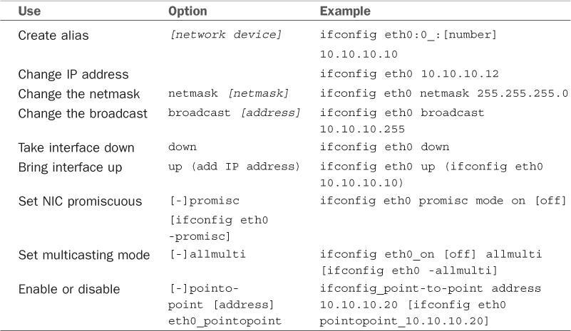
TABLE 18.1 ifconfig Options
The ifconfig man page shows other options that enable your machine to interface with a number of network types such as AppleTalk, Novell, IPv6, and others. Again, read the man page for details on these network types.
Note
Promiscuous mode causes the NIC to receive all packets on the network. It is often used to sniff a network. Multicasting mode enables the NIC to receive all multicast traffic on the network.
If no argument is given, ifconfig displays the status of active interfaces. For example, the output of ifconfig, without arguments and one active and configured NIC, looks similar to this:
Click here to view code image
matthew@seymour:~$ ifconfig
eth0 Link encap:Ethernet HWaddr 00:90:f5:8e:52:b5
UP BROADCAST MULTICAST MTU:1500 Metric:1
RX packets:0 errors:0 dropped:0 overruns:0 frame:0
TX packets:0 errors:0 dropped:0 overruns:0 carrier:0
collisions:0 txqueuelen:1000
RX bytes:0 (0.0 B) TX bytes:0 (0.0 B)
Interrupt:30 Base address:0xc000
lo Link encap:Local Loopback
inet addr:127.0.0.1 Mask:255.0.0.0
inet6 addr: ::1/128 Scope:Host
UP LOOPBACK RUNNING MTU:16436 Metric:1
RX packets:314 errors:0 dropped:0 overruns:0 frame:0
TX packets:314 errors:0 dropped:0 overruns:0 carrier:0
collisions:0 txqueuelen:0
RX bytes:25204 (25.2 KB) TX bytes:25204 (25.2 KB)
wlan0 Link encap:Ethernet HWaddr 00:16:ea:d4:58:88
inet addr:192.168.1.106 Bcast:192.168.1.255 Mask:255.255.255.0
inet6 addr: fe80::216:eaff:fed4:5888/64 Scope:Link
UP BROADCAST RUNNING MULTICAST MTU:1500 Metric:1
RX packets:325832 errors:0 dropped:0 overruns:0 frame:0
TX packets:302754 errors:0 dropped:0 overruns:0 carrier:0
collisions:0 txqueuelen:1000
RX bytes:207381807 (207.3 MB) TX bytes:40442735 (40.4 MB)
The output is easily understood. The inet entry displays the IP address for the interface. UP signifies that the interface is ready for use; BROADCAST denotes that the interface is connected to a network that supports broadcast messaging (ethernet); RUNNING means that the interface is operating; and LOOPBACK shows which device (lo) is the loopback address. The maximum transmission unit (MTU) on eth0 is 1500 bytes. This determines the size of the largest packet that can be transmitted over this interface (and is sometimes “tuned” to other values for performance enhancement). Metric is a number from 0 to 3 that relates to how much information from the interface is placed in the routing table. The lower the number, the smaller the amount of information.
The ifconfig command can be used to display information about or control a specific interface using commands that are listed in Table 18.1. For example, to deactivate the first Ethernet device on a host, use the ifconfigcommand, the interface name, and the command down:
Click here to view code image
matthew@seymour:~$ sudo ifconfig eth0 down
You can also configure and activate the device by specifying a hostname or IP address and network information. For example to configure and activate (bring up) the eth0 interface with a specific IP address, use the ifconfigcommand:
Click here to view code image
matthew@seymour:~$ sudo ifconfig eth0 192.168.2.9 netmask 255.255.255.0 up
If you have a host defined in your system’s /etc/hosts file (see the section “Network Configuration Files,” later in this chapter), you can configure and activate the interface according to the defined hostname like this:
Click here to view code image
matthew@seymour:~$ sudo ifconfig eth0 catcat.fakeurl.com up
/sbin/ip
In preparing for this edition, ifconfig still worked well on our testing system. However, it is losing favor as ip sees more use. This command works with a series of subcommands to perform its tasks. Many of the common subcommands also have short aliases, which are also listed here. Note that the IP addresses listed below are examples; the addresses in your network will likely be different.
To get information about all your network interfaces:
Click here to view code image
matthew@seymour:~$ sudo ip addr show
To assign an IP address to a specific interface, in this case “eth1”:
Click here to view code image
matthew@seymour:~$ sudo ip addr add 192.168.2.9 dev eth1
To remove an assigned IP address:
Click here to view code image
matthew@seymour:~$ sudo ip addr del 192.168.2.9 dev eth1
To enable a network interface:
Click here to view code image
matthew@seymour:~$ sudo ip link set eth1 up
To disable a network interface:
Click here to view code image
matthew@seymour:~$ sudo ip link set eth1 down
To check the routing table:
Click here to view code image
matthew@seymour:~$ sudo ip route show
To add a static route:
Click here to view code image
matthew@seymour:~$ sudo ip route add 10.10.30.0/24 via 192.168.50.100 dev eth0
To remove a static route:
Click here to view code image
matthew@seymour:~$ sudo ip route del 10.10.30.0/24
To add a default gateway:
Click here to view code image
matthew@seymour:~$ sudo ip route add default via 192.168.36.100
The next section explains how to configure your system to work with your LAN.
/sbin/route
The second command used to configure your network is the route command. route is used to build the routing tables (in memory) implemented for routing packets and to display the routing information. It is used after ifconfig has initialized the interface. route is normally used to set up static routes to other networks via the gateway or to other hosts. The command configuration is as follows:
Click here to view code image
route [options] [commands] [parameters]
To display the routing table, use the route command with no options. The display will look similar to this:
Click here to view code image
matthew@seymour:~$ route
Kernel IP routing table
Destination Gateway Genmask Flags Metric Ref Use Iface
192.168.1.0 * 255.255.255.0 U 2 0 0 wlan0
link-local * 255.255.0.0 U 1000 0 0 wlan0
default WirelessAccessPt 0.0.0.0 UG 0 0 0 wlan0
In the first column, Destination is the IP address (or, if the host is in /etc/hosts or /etc/networks, the hostname) of the receiving host. The default entry is the default gateway for this machine. The Gatewaycolumn lists the gateway that the packets must go through to reach their destination. An asterisk (*) means that packets go directly to the host. Genmask is the netmask. The Flags column can have several possible entries. In our example, U verifies that the route is enabled and G specifies that Destination requires the use of a gateway. The Metric column displays the distance to the Destination. Some daemons use this to figure the easiest route to the Destination. The Ref column is used by some UNIX flavors to convey the references to the route, but this isn’t used by Linux. The Use column indicates the number of times this entry has been looked up. Finally, the Iface column is the name of the interface for the corresponding entry.
Using the -n option to the route command gives the same information, substituting IP addresses for names and asterisks (*), and looks like this:
Click here to view code image
matthew@seymour:~$ route -n
Kernel IP routing table
Destination Gateway Genmask Flags Metric Ref Use Iface
192.168.1.0 0.0.0.0 255.255.255.0 U 2 0 0 wlan0
link-local 0.0.0.0 255.255.0.0 U 1000 0 0 wlan0
0.0.0.0 192.168.1.0 0.0.0.0 UG 0 0 0 wlan0
The route command can add to the table using the add option. With the add option, you can specify a host (-host) or a network (-net) as the destination. If no option is used, the route command assumes that you are configuring the host issuing the command. The most common uses for the route command are to add the default gateway for a host, for a host that has lost its routing table, or if the gateway address has changed. For example, to add a gateway with a specific IP address, you could use the following:
Click here to view code image
matthew@seymour:~$ sudo route add default gw 149.112.50.65
Note that you could use a hostname rather than an IP address if desired. Another common use is to add the network to the routing table right after using the ifconfig command to configure the interface. Assuming that the 208.59.243.0 entry from the previous examples was missing, replace it using the following command:
Click here to view code image
matthew@seymour:~$ sudo route add -net 208.59.243.0 netmask 255.255.255.0 dev
eth0
You also can use route to configure a specific host for a direct (point-to-point) connection. For example, suppose that you have a home network of two computers. One of the computers has a modem through which it connects to your business network. You typically work at the other computer. You can use the route command to establish a connection through specific hosts using the following command:
Click here to view code image
matthew@seymour:~$ sudo route add -host 198.135.62.25 gw 149.112.50.65
The preceding example makes the computer with the modem the gateway for the computer you are using. This type of command line is useful if you have a gateway or firewall connected to the Internet. There are many additional uses for the route command, such as manipulating the default packet size. See the man page for those uses.
/bin/netstat
The netstat command is used to display the status of your network. It has several parameters that can display as much or as little information as you prefer. The services are listed by sockets (application-to-application connections between two computers). You can use netstat to display the information in Table 18.2.
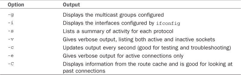
TABLE 18.2 netstat Options
Several other options are available for this command, but they are used less often. As with the route command, the man page can give you details about all options and parameters.
Network Configuration Files
As previously stated, five network configuration files can be modified to make changes to basic network interaction of your system:
![]() /etc/hosts—A listing of addresses, hostnames, and aliases
/etc/hosts—A listing of addresses, hostnames, and aliases
![]() /etc/services—Network service and port connections
/etc/services—Network service and port connections
![]() /etc/nsswitch.conf—Linux network information service configuration
/etc/nsswitch.conf—Linux network information service configuration
![]() /etc/resolv.conf—Domain Name Service (DNS) domain (search) settings
/etc/resolv.conf—Domain Name Service (DNS) domain (search) settings
![]() /etc/host.conf—Network information search order (by default, /etc/hosts and then DNS)
/etc/host.conf—Network information search order (by default, /etc/hosts and then DNS)
After these files are modified, the changes are active. As with most configuration files, you can add comments with a hash mark (#) preceding the comment. All these files have man pages, where you can find more information.
Adding Hosts to /etc/hosts
The /etc/hosts file is a map of IP to hostnames. If you are not using DNS or another naming service and you are connected to a large network, this file can get quite large and can be a real headache to manage. A small /etc/hosts file can look something like this:
Click here to view code image
127.0.0.1 localhost
127.0.1.1 optimus
# The following lines are desirable for IPv6 capable hosts
::1 ip6-localhost ip6-loopback
fe00::0 ip6-localnet
ff00::0 ip6-mcastprefix
ff02::1 ip6-allnodes
ff02::2 ip6-allrouters
ff02::3 ip6-allhosts
The first entry is for the loopback entry. The second is for the name of the machine. If no naming service is in use on the network, the only host that myhost recognizes by name is yourhost. (IP addresses on the network can still be used.)
Service Settings in /etc/services
The /etc/services file maps port numbers to services. The first few lines look similar to this. (The /etc/services file can be quite long, more than 500 lines.)
Click here to view code image
# Each line describes one service, and is of the form:
#
# service-name port/protocol [aliases ...] [# comment]
tcpmux 1/tcp # TCP port service multiplexer
tcpmux 1/udp # TCP port service multiplexer
rje 5/tcp # Remote Job Entry
rje 5/udp # Remote Job Entry
echo 7/tcp
echo 7/udp
discard 9/tcp sink null
discard 9/udp sink null
systat 11/tcp users
Typically, there are two entries for each service because most services can use either TCP or UDP for their transmissions. Usually after /etc/services is initially configured, you do not need to change it.
Using /etc/nsswitch.conf After Changing Naming Services
This file was initially developed by Sun Microsystems to specify the order in which services are accessed on the system. A number of services are listed in the /etc/nsswitch.conf file, but the most commonly modified entry is the hosts entry. A portion of the file can look like this:
Click here to view code image
passwd: compat
group: compat
shadow: compat
hosts: files dns mdns
networks: files
protocols: db files
services: db files
ethers: db files
rpc: db files
netgroup: nis
This tells services that they should consult standard UNIX/Linux files for passwd, shadow, and group (/etc/passwd, /etc/shadow, /etc/group, respectively) lookups. For host lookups, the system checks /etc/hosts; if there is no entry, it checks DNS. The commented hosts entry lists the possible values for hosts. Edit this file only if your naming service has changed.
Setting a Name Server with /etc/resolv.conf
/etc/resolv.conf is used by DNS, the Domain Name Service. The following is an example of resolv.conf:
nameserver 192.172.3.8
nameserver 192.172.3.9
search mydomain.com
This sets the nameservers and the order of domains for DNS to use. The contents of this file are set automatically if you use DHCP (see the “Dynamic Host Configuration Protocol” section later in this chapter).
Starting with 12.04, there was a pretty big change in how Ubuntu uses this file. Management of resolv.conf has been turned over to a program called resolvconf, which works with DHCP, with a Network Manager plug-in, and with /etc/network/interfaces to automatically generate a list of nameservers and domains to list in /etc/resolv.conf. What this means is that any manual changes made here are eventually overwritten and lost.
If you have a static IP configuration, you should now list each of your static IP interfaces as dns-nameservers, dns-search and dns-domain entries in /etc/network/interfaces.
You can override the configuration for resolvconf or add entries to it in the following files in /etc/resolvconf/resolv.conf.d/ directory:
![]() base—This file is used when no other data can be found.
base—This file is used when no other data can be found.
![]() head—This file is used as the header for resolv.conf, and you can use it to ensure a specific DNS server is always the first one on the list used.
head—This file is used as the header for resolv.conf, and you can use it to ensure a specific DNS server is always the first one on the list used.
![]() original—This file is a backup copy of your original resolv.conf file from the time when the resolvconf program was installed.
original—This file is a backup copy of your original resolv.conf file from the time when the resolvconf program was installed.
![]() tail—This file is used as a tail, appended to the end of the auto-generated resolv.conf file.
tail—This file is used as a tail, appended to the end of the auto-generated resolv.conf file.
The format in these files is the same as the traditional format for /etc/resolv.conf. Splitting things this way gives more granular control while also allowing for DHCP auto-configuration.
Setting DNS Search Order with /etc/host.conf
The /etc/host.conf file lists the order in which your machine searches for hostname resolution. The following is the default /etc/host.conf file:
order hosts, bind
In this example, the host checks the /etc/hosts file first and then performs a DNS lookup. A couple more options control how the name service is used. The only reason to modify this file is if you use NIS for your name service or you want one of the optional services. The nospoof option can be a good option for system security. It compares a standard DNS lookup to a reverse lookup (host-to-IP then IP-to-host) and fails if the two don’t match. The drawback is that often when proxy services are used, the lookup fails, so you want to use this with caution.
Using Graphical Configuration Tools
Ubuntu has made some big improvements to how desktop users may configure networking using graphical configuration tools. For most people, all you need to know is contained in Chapter 1, “Installing Ubuntu and Post-Installation Configuration,” in the section about Network Manager. For others, you may configure your network connections by right-clicking the networking icon on your top panel and choosing Edit Connections from the menu, as shown in Figure 18.1. From the Network Connections window that opens, you may select from various types of connections to configure, including Wired, Wireless, Mobile Broadband, VPN, and DSL, as shown in Figure 18.2. By default, each is set to autoconfigure, and most users never need to change the settings available here. If you do need to, just choose the appropriate tab and click the Add button; you can then configure and fine-tune settings as needed, such as in the wireless connection example in Figure 18.3.
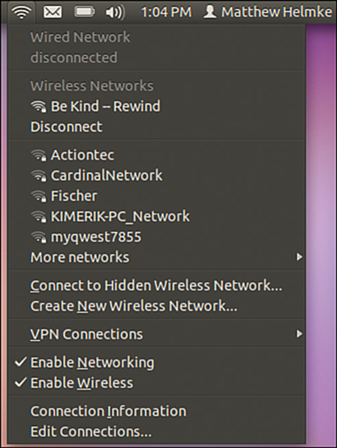
FIGURE 18.1 Use nm-connection-editor to configure your network devices.
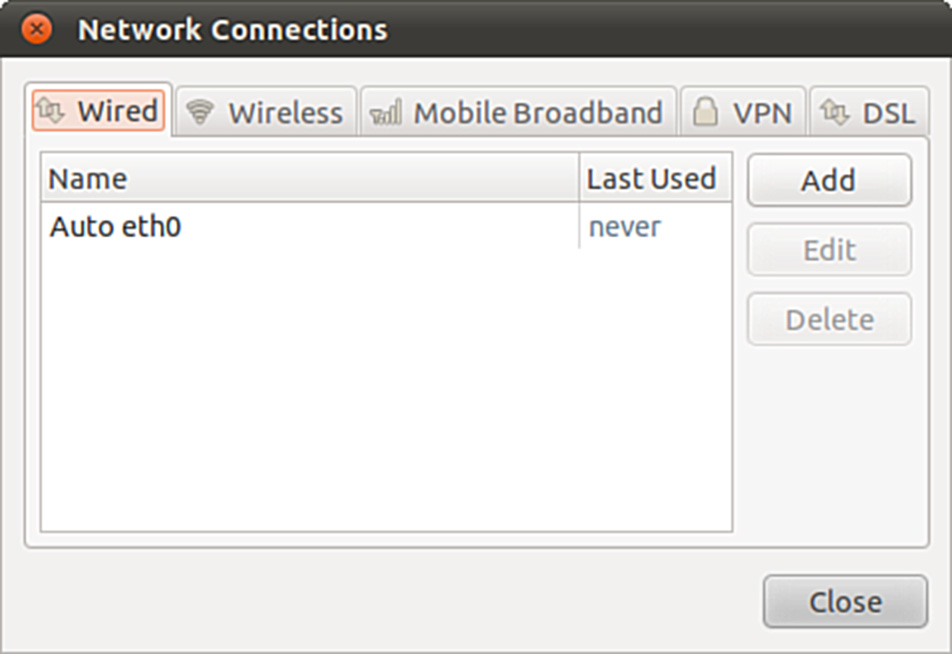
FIGURE 18.2 Choose the connection type to configure from the tabs in Network Connections.
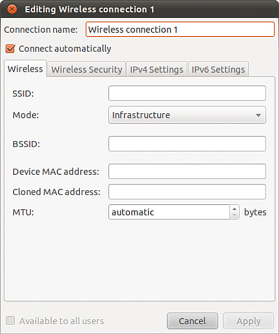
FIGURE 18.3 Assign a static IP address to a network interface.
Dynamic Host Configuration Protocol
As its name implies, Dynamic Host Configuration Protocol (DHCP) configures hosts for connection to your network. DHCP enables a network administrator to configure all TCP/IP parameters for each host as he connects to the network after activation of a NIC. These parameters include automatically assigning an IP address to a NIC, setting name server entries in /etc/resolv.conf, and configuring default routing and gateway information for a host. This section first describes how to use DHCP to obtain IP address assignment for your NIC and then how to quickly set up and start a DHCP server using Ubuntu.
Note
You can learn more about DHCP by reading RFC 2131, “Dynamic Host Configuration Protocol,” at www.ietf.org/rfc/rfc2131.txt.
How DHCP Works
DHCP provides persistent storage of network parameters by holding identifying information for each network client that might connect to the network. The three most common pairs of identifying information are as follows:
![]() Network subnet/host address—Used by hosts to connect to the network at will
Network subnet/host address—Used by hosts to connect to the network at will
![]() Subnet/hostname—Enables the specified host to connect to the subnet
Subnet/hostname—Enables the specified host to connect to the subnet
![]() Subnet/hardware address—Enables a specific client to connect to the network after getting the hostname from DHCP
Subnet/hardware address—Enables a specific client to connect to the network after getting the hostname from DHCP
DHCP also allocates to the client’s temporary or permanent network (IP) addresses. When a temporary assignment, known as a lease, elapses, the client can request to have the lease extended, or, if the address is no longer needed, the client can relinquish the address. For hosts that will be permanently connected to a network with adequate addresses available, DHCP allocates infinite leases.
DHCP offers your network some advantages. First, it shifts responsibility for assigning IP addresses from the network administrator (who can accidentally assign duplicate IP addresses) to the DHCP server. Second, DHCP makes better use of limited IP addresses. If a user is away from the office for whatever reason, the user’s host can release its IP address for use by other hosts.
Like most things in life, DHCP is not perfect. Servers cannot be configured through DHCP alone because DNS does not know what addresses that DHCP assigns to a host. This means that DNS lookups are not possible on machines configured through DHCP alone; therefore, services cannot be provided. However, DHCP can make assignments based on DNS entries when using subnet/hostname or subnet/hardware address identifiers.
Note
The problem of using DHCP to configure servers using registered hostnames is being addressed by Dynamic DNS which, when fully developed, will enable DHCP to register IP addresses with DNS. This will enable you, for example, to register a domain name (such as matthewhelmke.com) and be able to easily access that domain’s web server without needing to use static IP addressing of a specific host. The largest hurdle to overcome is the security implication of enabling each host connecting to the system to update DNS. A few companies, such as Dyn.com (www.dyndns.org/), are already offering Dynamic DNS services and have clients for Linux.
Activating DHCP at Installation and Boot Time
Ubuntu automatically defaults your network interfaces to using DHCP because it is the simplest way of setting up a network interface. With dynamic, or DHCP-assigned IP addressing schemes for your NIC, the broadcast address is set at 255.255.255.255 because dhclient, the DHCP client used for IP configuration, is initially unaware of where the DHCP server is located, so the request must travel every network until a server replies.
You can find the instruction to use DHCP for your NIC /etc/network/interfaces, with a line that says dhcp.
Other settings specific to obtaining DHCP settings are saved in the file named dhclient.conf under the /etc/dhcp3/dhclient.conf directory and are documented in the dhclient.conf man page. More than 100 options are also documented in the dhcpoptions man page.
However, using DHCP is not that complicated. If you want to use DHCP and know that there is a server on your network, you can quickly configure your NIC by using the dhclient, as follows:
Click here to view code image
matthew@seymour:~$ sudo dhclient
Internet Systems Consortium DHCP Client V3.1.3
Copyright 2004-2009 Internet Systems Consortium.
All rights reserved.
For info, please visit https://www.isc.org/software/dhcp/
Listening on LPF/eth0/00:90:f5:8e:52:b5
Sending on LPF/eth0/00:90:f5:8e:52:b5
Listening on LPF/virbr0/ee:1a:62:7e:e2:a2
Sending on LPF/virbr0/ee:1a:62:7e:e2:a2
Listening on LPF/wlan0/00:16:ea:d4:58:88
Sending on LPF/wlan0/00:16:ea:d4:58:88
Sending on Socket/fallback
DHCPDISCOVER on eth0 to 255.255.255.255 port 67 interval 7
DHCPDISCOVER on wlan0 to 255.255.255.255 port 67 interval 3
DHCPOFFER of 192.168.1.106 from 192.168.1.1
DHCPREQUEST of 192.168.1.106 on wlan0 to 255.255.255.255 port 67
DHCPACK of 192.168.1.106 from 192.168.1.1
bound to 192.168.1.106 -renewal in 35959 seconds.
In this example, the first Ethernet device, eth0, has been assigned an IP address of 192.168.1.106 from a DHCP server at 192.168.1.1. The renewal will take place in 35959 seconds, or about 10 hours. (Cool tip: Google converts this for you if you search for 35959 seconds in hours.)
DHCP Software Installation and Configuration
Installation of the DHCP client and server is fairly straightforward, mainly because Ubuntu already includes dhclient in a default installation but also because installing software is easy using synaptic or apt-get.
DHCP dhclient
DHCP is automatically enabled when you install Ubuntu, so you do not need to worry about having to enable it. The DHCP client, dhclient, sends a broadcast message that the DHCP server replies to with networking information for your host. After it has this, you’re done.
You can, however, fine-tune how dhclient works and where and how it obtains or looks for DHCP information. You probably will not need to take this additional effort; but if you do, you can create and edit a file named dhclient.conf and save it in the /etc directory with your settings.
Caution
You should not just go ahead and overwrite your dhclient.conf with any old file because doing so could lead you to painful networking problems. Instead, copy the file like this:
Click here to view code image
matthew@seymour:~$ sudo cp /etc/dhcp3/dhclient.conf/ etc/dhcp3/dhclient.conf.backup
That way, if anything goes wrong, you can then use the backup to restore the original settings by copying it back to its original location in place of the modified file.
A few of the dhclient.conf options include the following:
![]() timeout time ;—How long to wait before giving up trying. (The default is 60 seconds.)
timeout time ;—How long to wait before giving up trying. (The default is 60 seconds.)
![]() retry time ;—How long to wait before retrying. (The default is 5 minutes.)
retry time ;—How long to wait before retrying. (The default is 5 minutes.)
![]() select-timeout time ;—How long to wait before selecting a DHCP offer. (The default is 0 seconds.)
select-timeout time ;—How long to wait before selecting a DHCP offer. (The default is 0 seconds.)
![]() reboot time ;—How long to wait before trying to get a previously set IP. (The default is 10 seconds.)
reboot time ;—How long to wait before trying to get a previously set IP. (The default is 10 seconds.)
![]() renew date ;—When to renew an IP lease, where date is in the form of weekday year/month/day hour:minute:second, such as in 3 2010/7/7 22:01:01 for Wednesday, July 7, 2010, at 10:01 p.m.
renew date ;—When to renew an IP lease, where date is in the form of weekday year/month/day hour:minute:second, such as in 3 2010/7/7 22:01:01 for Wednesday, July 7, 2010, at 10:01 p.m.
See the dhclient.conf man page for more information on additional settings.
DHCP Server
Again, the easiest way to install the DHCP server on your computer is to use either synaptic or apt-get to retrieve the dhcp3-server package. If you are so inclined, you can go to the Internet Software Consortium (ISC)website and download and build the source code yourself (www.isc.org/). However, we recommend you stay with the package in the Ubuntu repositories because it will be easy to update if there are security updates.
If you decide to install from a source downloaded from the ISC website, the installation is straightforward. Just unpack your tar file, run ./configure from the root of the source directory, run make, and finally, if there are no errors, run make install. This puts all the files used by the DHCP daemon in the correct places. If you have the disk space, it is best to leave the source files in place until you are sure that DHCP is running correctly; otherwise, you can delete the source tree.
Note
For whichever installation method you choose, be sure that a file called /etc/dhcp3/dhcpd.leases is created. The file can be empty, but it does need to exist for dhcpd to start properly.
Using DHCP to Configure Network Hosts
Configuring your network with DHCP can look difficult but is actually easy if your needs are simple. The server configuration can take a bit more work if your network is more complex and depending on how much you want DHCP to do.
Configuring the server takes some thought and a little bit of work. Luckily, the work involves editing only a single configuration file, /etc/dhcp3/dhcpd.conf. To start the server at boot time, use the service or ntsysvcommands.
The /etc/dhcp3/dhcpd.conf file contains all the information needed to run dhcpd. Ubuntu includes a sample dhcpd.conf in /usr/share/doc/dhcp*/dhcpd.conf.sample. The DHCP server source files also contain a sample dhcpd.conf file.
You can think of the /etc/dhcp3/dhcpd.conf file at as a three-part file. The first part contains configurations for DHCP itself. The configurations include the following:
![]() Setting the domain name—option domain-name "example.org"
Setting the domain name—option domain-name "example.org"
![]() Setting DNS servers—option domain-name-servers ns1.example.org, ns2.example.org (IP addresses can be substituted.)
Setting DNS servers—option domain-name-servers ns1.example.org, ns2.example.org (IP addresses can be substituted.)
![]() Setting the default and maximum lease times—default-lease-time 3600 and max-lease-time 14400
Setting the default and maximum lease times—default-lease-time 3600 and max-lease-time 14400
Other settings in the first part include whether the server is the primary (authoritative) server and what type of logging DHCP should use. These settings are considered defaults, and you can override them by the subnet and host portion of the configuration in more complex situations.
Note
The dhcpd.conf file requires semicolons (;) after each command statement. If your configuration file has errors or runs improperly, check for this.
The next part of the dhcpd.conf deals with the different subnets that your DHCP server serves; this section is quite straightforward. Each subnet is defined separately and can look like this:
Click here to view code image
subnet 10.5.5.0 netmask 255.255.255.224 {
range 10.5.5.26 10.5.5.30;
option domain-name-servers ns1.internal.example.org;
option domain-name "internal.example.org";
option routers 10.5.5.1;
option broadcast-address 10.5.5.31;
default-lease-time 600;
max-lease-time 7200;
}
This defines the IP addressing for the 10.5.5.0 subnet. It defines the IP address ranging from 10.5.5.26 through 10.5.5.30 to be dynamically assigned to hosts that reside on that subnet. This example shows that you can set any TCP/IP option from the subnet portion of the configuration file. It shows which DNS server the subnet will connect to, which can be good for DNS server load balancing, or which can be used to limit the hosts that can be reached through DNS. It defines the domain name, so you can have more than one domain on your network. It can also change the default and maximum lease time.
If you want your server to ignore a specific subnet, you can do so as follows:
Click here to view code image
subnet 10.152.187.0 netmask 255.255.255.0 {
}
This defines no options for the 10.152.187.0 subnet; therefore, the DHCP server ignores it.
The last part of your dhcp.conf is for defining hosts. This can be good if you want a computer on your network to have a specific IP address or other information specific to that host. The key to completing the host section is to know the hardware address of the host. As you learned in the “Hardware Devices for Networking” section, earlier in this chapter, the hardware address is used to differentiate the host for configuration. You can obtain your hardware address by using the ifconfig command as described previously. The hardware address is on the eth0 line labeled Hwaddr.
Click here to view code image
host hopper {
hardware ethernet 08:00:07:26:c0:a5;
fixed-address hopper.matthewhelmke.com;
}
This example takes the host with the hardware address 08:00:07:26:c0:a5 and does a DNS lookup to assign the IP address for hopper.matthewhelmke.com to the host.
DHCP can also define and configure booting for diskless clients like this:
Click here to view code image
host bumblebee {
hardware ethernet 0:0:c0:5d:bd:95;
filename "vmunix.bumblebee";
server-name "kernigan.matthewhelmke.com";
}
The diskless host bumblebee gets its boot information from server kernigan.matthewhelmke.com and uses vmunix.bumblebee kernel. All other TCP/IP configuration can also be included.
Caution
Remember, to avoid problems, only one DHCP server should be configured on a local network. Your DHCP might not work correctly on a LAN with hosts running outdated legacy operating systems. Often, Windows NT servers have the Windows DHCP server installed by default. Because there is no configuration file for NT to sort through, that DHCP server configures your host before the Linux server if both machines are on the same LAN. Check your NT servers for this situation and disable DHCP on the NT server; afterward, your other DHCP-enabled hosts should configure correctly. Also check to make sure that there are no conflicts if you use a cable or DSL modem, wireless access point (WAP), or other intelligent router on your LAN that can provide DHCP.
Other Uses for DHCP
A whole host of options can be used in dhcpd.conf: Entire books are dedicated to DHCP. The most comprehensive book is The DHCP Handbook, available at www.dhcp-handbook.com/. You can define NIS domains, configure NetBIOS, set subnet masks, and define time servers or many other types of servers (to name a few of the DHCP options you can use). The preceding example gets your DHCP server and client up and running.
The DHCP server distribution contains an example of the dhcpd.conf file that you can use as a template for your network. The file shows a basic configuration that can get you started with explanations for the options used.
Wireless Networking
Linux has had support for wireless networking since the first standards were developed in the early 1990s. With computers getting smaller and smaller, the uses for wireless networking increased; meanwhile, the transmission speeds are increasing all the time. There are several ways to create a wireless network. The following sections introduce you to several Linux commands you can use to initialize, configure, and manage wireless networking on your Ubuntu system.
Support for Wireless Networking in Ubuntu
The Linux kernel that ships with Ubuntu provides extensive support for wireless networking. Related wireless tools for configuring, managing, or displaying information about a wireless connection include the following:
![]() iwconfig—Sets the network name, encryption, transmission rate, and other features of a wireless network interface
iwconfig—Sets the network name, encryption, transmission rate, and other features of a wireless network interface
![]() iwlist—Displays information about a wireless interface, such as rate, power level, or frequency used
iwlist—Displays information about a wireless interface, such as rate, power level, or frequency used
![]() iwpriv—Sets optional features, such as roaming, of a wireless network interface
iwpriv—Sets optional features, such as roaming, of a wireless network interface
![]() iwspy—Shows wireless statistics of a number of nodes
iwspy—Shows wireless statistics of a number of nodes
Support varies for wireless devices, but most modern (that is, post-2005) wireless devices should work with Ubuntu. In general, Linux wireless device software (usually in the form of a kernel module) support the creation of an Ethernet device that can be managed by traditional interface tools such as ifconfig—with wireless features of the device managed by the various wireless software tools.
For example, when a wireless networking device is first recognized and initialized for use, the driver most likely reports a new device:
Click here to view code image
zd1211rw 5-4:1.0: firmware version 4725
zd1211rw 5-4:1.0: zd1211b chip 050d:705c v4810 \
high 00-17-3f AL2230_RF pa0 G—ns
zd1211rw 5-4:1.0: eth2
usbcore: registered new interface driver zd1211rw
This output (from the dmesg command) shows that the eth2 device has been reported. If DHCP is in use, the device should automatically join the nearest wireless subnet and be automatically assigned an IP address. If not, the next step is to use a wireless tool such as iwconfig to set various parameters of the wireless device. The iwconfig command, along with the device name (eth2 in this example), shows the status:
Click here to view code image
matthew@seymour:~$ iwconfig eth2
eth2 IEEE 802.11b/g ESSID:"SKY35120" Nickname:"zd1211"
Mode:Managed Frequency:2.462 GHz \
Access Point: 00:18:4D:06:8E:2A
Bit Rate=24 Mb/s
Encryption key:0EFD-C1AF-5C8D-B2C6-7A89-3790-07A7-AC64-0AB5\
-C36E-D1E9-A230-1DB9-D227-2EB6-D6C8 Security mode:open
Link Quality=100/100 Signal level=82/100
Rx invalid nwid:0 Rx invalid crypt:0 Rx invalid frag:0
Tx excessive retries:0 Invalid misc:0 Missed beacon:0
This example shows a 24Mbps connection to a network named SKY35120. To change a parameter, such as the transmission rate, use a command-line option with the iwconfig command like this:
Click here to view code image
matthew@seymour:~$ sudo iwconfig eth2 rate 11M
Other options supported by the iwconfig command include essid, used to set the NIC to connect to a specific network by name; mode, used to enable the NIC to automatically retrieve settings from an access point or connect to another wireless host; and freq, to set a frequency to use for communication. Additional options include channel, frag, enc (for encryption), power, and txpower. Details and examples of these options are in the iwconfig man page.
You can then use the ifconfig command or perhaps a graphical Ubuntu tool to set the device networking parameters, and the interface will work as on a hardwired LAN. One handy output of the iwconfig command is the link quality output, which you can use in shell scripts or other graphical utilities for signal-monitoring purposes.
Advantages of Wireless Networking
Advantages of wireless networking are its mobility and potential range. If you have a large enough antenna network, your network can stretch many miles. This would be an expensive network, but one that would easily break out of the brick-and-mortar confines of the office.
Wireless networking is also a great advantage to college campuses, eliminating the need to tear through walls to install cabling as more and more students expect to have a network connection in their dorm rooms. Wireless networking cards are very reasonable in price and can easily be issued to each student as required.
Home networkers can also benefit from wireless networking. It is a potential solution for those who cannot make wired network modifications to their homes. In addition, wireless networking removes the unsightly wires running along baseboards and ceilings that are required to connect computers in different rooms. With a wireless home network, you are not even confined to inside the house. Depending on the transmit power of your router, you can sit out in your backyard and watch clouds drifting by as you type away.
Choosing the right types of wireless devices is an important decision. The next sections discuss some of the basic differences between current protocols used for wireless networking.
Choosing from Among Available Wireless Protocols
The Institute of Electrical and Electronics Engineers (IEEE) started to look seriously at wireless networking in 1990. This is when the 802.11 standard was first introduced by the Wireless Local Area Networks Standards Working Group. The group based the standard roughly around the architecture used in cellular phone networks. The wireless network is controlled by a base station, which can be just a transmitter attached to the network or, more commonly these days, a router.
Larger networks can use more than one base station. Networks with more than one base station are usually referred to as distribution systems. You can use a distribution system to increase coverage area and support roaming of wireless hosts. You can also use external omnidirectional antennas to increase coverage area, or if required, you can use point-to-point or directional antennas to connect distant computers or networks. Right now, the least expensive wireless Linux networks are built using devices (such as access points or NICs) supporting 802.11b, although the faster 802.11g devices tend to get more shelf space. Devices are available marketed as N or Pre-N, meaning that they implement a draft standard, while the IEEE carry on debating the full N standard. Significantly more power throughput and range are promised by hardware that supports N, but this specification has yet to be formally agreed on and so implementations are not necessarily standard.
An early standard, 802.11a, offers greater transmission rates than 802.11b, and a number of 802.11a wireless NICs are available. (Some products provide up to 72Mbps, but do not work with 802.11b devices.) Wireless networking devices based on 802.11g, which has the speed improvement of 802.11a and is compatible with 802.11b, are common. Other wireless protocols include Bluetooth, which provides up to 720Kbps data transfers. Bluetooth is intended for short-range device communications (such as for a printer) and supports a typical range of only 10 meters. Bluetooth is unlike IrDA, which requires line of sight (devices that are aimed at each other). Bluetooth use conflicts with 802.11 networks because it also uses the 2.4GHz band. You can find out more at www.bluetooth.com/.
The 802.11 standard specifies that wireless devices use a frequency range of 2400MHz to 2483.5MHz. This is the standard used in North America and Europe. In Japan, however, wireless networks are limited to a frequency range of 2471MHz to 2479MHz because of Japanese regulations. Within these ranges, each network is given up to 79 nonoverlapping frequency channels to use. This reduces the chance of two closely located wireless networks using the same channel at the same time. It also allows for channel hopping, which can be used for security.
Beyond the Network and onto the Internet
Ubuntu supports Internet connections and the use of Internet resources in many different ways. You will find a wealth of Internet-related software included with this book’s version of Ubuntu, and you can download hundreds of additional free utilities from a variety of sources. To use them, you must have a working Internet connection.
In this section, you learn how to set up an Internet connection in Ubuntu using a modem and Point-to-Point Protocol (PPP) as well as other connection methods, including digital subscriber line (DSL) and cable modem services. Just a few years ago, getting a dial-up connection working was difficult—hence, an entire chapter of this book was devoted to it. Today, as long as you have a hardware modem, dial-up configuration is simple. The Ubuntu developers and the wider Linux community have made great progress in making connectivity easier.
Although many experienced Linux users continue to use manual scripts to establish their Internet connectivity, new users and experienced system administrators alike will find Ubuntu’s graphical network configuration interface much easier to use. You learn how to use the Internet Connection Wizard in this chapter and how to configure Ubuntu to provide dial-in PPP support. The chapter also describes how to use Roaring Penguin’s DSL utilities to manage connectivity through a cable modem connection.
Common Configuration Information
Although Ubuntu enables great flexibility in configuring Internet connections, that flexibility comes at the price of an increase in complexity. To configure Internet connectivity in Ubuntu, you must know more about the details of the connection process than you can learn from the information typically provided by your Internet service provider (ISP). In this section, you learn what to ask about and how to use the information.
Some ISPs are unaware of Linux or unwilling to support its use with their service. Fortunately, that attitude is rapidly changing, and the majority of ISPs offer services using standard protocols that are compatible with Linux, even if they (or their technical support people) aren’t aware that their own ISPs are Linux friendly. You just need to press a little for the information you require.
If you are one of the few remaining people using a dial-up modem account (referred to in Linux as PPP for the Point-to-Point Protocol it uses), your ISP will provide your computer with a static or dynamic Internet Protocol (IP)address. A dynamic IP address changes each time you dial in, whereas a static IP address remains the same. The ISP also might automatically provide your computer with the names of the Domain Name Service (DNS) servers. You need to know the telephone number that your computer will dial in to for making the connection; your ISP supplies that number, too. You also need a working modem and need to know the device name of the modem (usually /dev/modem).
Note
Most IP addresses are dynamically assigned by ISPs; ISPs have a pool of addresses, and you get whatever address is available. From the ISP’s viewpoint, a small number of addresses can serve a large number of people because not everyone will be online at the same time. For most Internet services, a dynamic IP works well because it is the ISP’s job to route that information to you, and it sits in the middle—between you and the service you want to use. But a dynamic IP address changes, and if someone needs to find you at the same address (if you run a website or a file transfer site, for example), an IP that changes every time you log on does not work well. For that, you need a static IP. Because your ISP cannot reuse that IP with its other customers, it will likely charge you more for a static IP than for a dynamic IP. Average consumers do not need the benefit of a static IP and so are happy paying less for a dynamically assigned IP. Also, the DNS information can be provided automatically by the ISP by DHCP.
If you are using DSL access or a cable modem, you might have a dynamic IP provided through DHCP, or you might be assigned a static IP. You might automatically be provided with the names of the DNS servers if you use DHCP, or you might have to set up DNS manually (in which case, you have to know the IP addresses of the DNS servers).
In all cases, you have to know your username, your password, and for the configuration of other services, the names of the mail servers and the news server. You can obtain this information from your ISP if you specifically ask for it.
Note
The information in this book helps you understand and avoid many connection issues, but you might experience connection problems. Keep the telephone number of the technical help service for your ISP on hand in case you cannot establish a connection. But be aware that few ISPs offer Linux support, and you might need to seek help from a Linux-savvy friend or a Linux user group if your special circumstances cannot be handled from the knowledge you gain from this book. Of course, the best place to look is on the Internet.
Configuring Digital Subscriber Line Access
Ubuntu also supports the use of a digital subscriber line (DSL) service. Although it refers to the different types of DSL available as xDSL (which includes ADSL, IDSL, SDSL, and other flavors of DSL service), you can configure all of them using the Internet Connection Wizard. DSL service generally provides 256Kbps to 24Mbps transfer speeds and transmits data over copper telephone lines from a central office to individual subscriber sites (such as your home). Many DSL services (technically, cable rather than DSL) provide asymmetric speeds with download speeds greater than upload speeds.
Note
DSL service is an “always-on” type of Internet service, although you can turn off the connection under Ubuntu using the network configuration tool found under System, Administration, Network. An always-on connection exposes your computer to malicious abuse from crackers who trawl the Internet attempting to gain access to other computer systems. In addition to the capability to turn off such connections, Ubuntu is preconfigured to not listen on any network ports, which means that any attempts to gain access to your computer fail because Ubuntu rejects the request. This is the Ubuntu equivalent to surrounding your computer with a 12-foot steel fence.
A DSL connection requires that you have an Ethernet NIC (sometimes a USB interface that is not easily supported in Linux) in your computer or notebook. Many users also configure a gateway, firewall, or other computer with at least two NICs to share a connection with a LAN. We looked at the hardware and protocol issues earlier in this chapter. Advanced configuration of a firewall or router, other than what was addressed during your initial installation of Ubuntu, is beyond the scope of this book.
Understanding PPP over Ethernet
Establishing a DSL connection with an ISP providing a static IP address is easy. Unfortunately, many DSL providers use a type of PPP protocol named Point-to-Point Protocol over Ethernet (PPPoE) that provides dynamic IP address assignment and authentication by encapsulating PPP information inside Ethernet frames. Roaring Penguin’s rp-pppoe clients are available from the Roaring Penguin site (https://www.roaringpenguin.com/files/download/rp-pppoe-3.11.tar.gz), and these clients make the difficult-to-configure PPPoE connection much easier to deal with. You can download and install newer versions. (See the Roaring Penguin link in the “References” section at the end of this chapter.)
Note
When ISPs originally started to roll out ADSL services, they often provided the ADSL modems. Today, however, in much of the world these modems are optional, which is a good thing because many people choose to purchase a router with an built-in modem to create a dedicated connection. In the United States, these devices are rare, but you can usually replace the supplied modem with an aftermarket modem if you want to spend the money. Either way, using a router can save many headaches and enables you to easily connect more than one computer to an Internet connection. Note that if you are using a cable connection, they usually come with an Ethernet cable, in which case you just need a router (which is pretty much how all Internet access works in the United States because combination modem/router devices are rare in the United States). Check with your ISP before buying to ensure that whatever router you do end up with can be supported by them. You might find that your ISP even supplies a router as part of the package.
Configuring a PPPoE Connection Manually
You should only need to use these steps if you are using a modem supplied by your ISP, and not a router. The basic steps involved in manually setting up a DSL connection using Ubuntu involve connecting the proper hardware and then running a simple configuration script if you use rp-pppoe from Roaring Penguin.
First, connect your DSL modem to your telephone line, and then plug in your Ethernet cable from the modem to your computer’s NIC. If you plan to share your DSL connection with the rest of your LAN, you need at least two network cards: designated eth0 (for your LAN) and eth1 (for the DSL connection).
The following example assumes that you have more than one computer and will share your DSL connection on a LAN.
First, log in as root, and ensure that your first eth0 device is enabled and up (perhaps using the ifconfig command). Next, bring up the other interface, but assign a null IP address like this:
Click here to view code image
matthew@seymour:~$ sudo ifconfig eth1 0.0.0.0 up
Now use the adsl-setup command to set up your system, as follows:
Click here to view code image
matthew@seymour:~$ sudo /sbin/adsl-setup
You are presented with a text script and asked to enter your username and the Ethernet interface used for the connection (such as eth1). You are then asked to use “on-demand” service or have the connection stay up all the time (until brought down by the root operator). You can also set a timeout in seconds, if desired. You are then asked to enter the IP addresses of your ISP’s DNS servers if you haven’t configured the system’s /etc/resolv.conf file.
After that, you are prompted to enter your password two times and must choose the type of firewall and IP masquerading to use. (You learned about IP masquerading in the “Using IP Masquerading in Ubuntu” section, earlier in this chapter.) The actual configuration is done automatically. Using a firewall is essential today, so choose this option unless you intend to craft your own set of firewall rules (a discussion of which is beyond the scope of this book). After you have chosen your firewall and IP masquerading setup, you are asked to confirm, save, and implement your settings. You are also given a choice to allow users to manage the connection, a handy option for home users.
Changes are made to your system’s /etc/sysconfig/network-scripts/ifcfg-ppp0, /etc/resolv.conf, /etc/ppp/pap-secrets, and /etc/ppp/chap-secrets files.
After configuration has finished, use the adsl-start command to start a connection and DSL session, like this:
Click here to view code image
matthew@seymour:~$ sudo /sbin/adsl-start
The DSL connection should be nearly instantaneous, but if problems occur, check to make sure that your DSL modem is communicating with the phone company’s central office by examining the status LEDs on the modem. Because this varies from modem to modem, consult your modem user’s manual.
Make sure all cables are properly attached, that your interfaces are properly configured and that you have entered the correct information to the setup script.
If IP masquerading is enabled, other computers on your LAN on the same subnet address (such as 192.168.0.XXX) can use the Internet but must have the same /etc/resolv.conf name server entries and a routing entry with the DSL-connected computer as a gateway. For example, if the host computer with the DSL connection has an IP address of 192.168.0.1, and other computers on your LAN use addresses in the 192.168.0.XXX range, use the route command on each computer like this:
Click here to view code image
matthew@seymour:~$ sudo route add default gw 192.168.0.1
Note that you can also use a hostname instead if each computer has an /etc/hosts file with hostname and IP address entries for your LAN. To stop your connection, use the adsl-stop command:
Click here to view code image
matthew@seymour:~$ sudo /sbin/adsl-stop
Configuring Dial-Up Internet Access
Most ISPs provide dial-up connections supporting PPP because it is a fast and efficient protocol for using TCP/IP over serial lines. PPP is designed for two-way networking; TCP/IP provides the transport protocol for data. One hurdle faced by new Ubuntu users is how to set up PPP and connect to the Internet. It is not necessary to understand the details of the PPP protocol to use it, and setting up a PPP connection is easy. You can configure the PPP connections manually using the command line or graphically during an X session using Ubuntu’s Network Configuration Tool. Each approach produces the same results.
PPP uses several components on your system. The first is a daemon called pppd, which controls the use of PPP. The second is a driver called the high-level data link control (HDLC), which controls the flow of information between two machines. A third component of PPP is a routine called chat that dials the other end of the connection for you when you want it to. Although PPP has many “tunable” parameters, the default settings work well for most people.
Ubuntu includes some useful utilities to get your dial-up connection up and running. In this section, we look at two options that will have you on the Internet in no time.
The first way is to configure a connection using pppconfig, a command-line utility to help you to configure specific dial-up connection settings.
Enter the following command:
Click here to view code image
matthew@seymour:~$ sudo pppconfig
Before you connect for the first time, you need to add yourself to both the dip and dialout groups by using these commands:
Click here to view code image
matthew@seymour:~$ sudo adduser YOURNAMEHERE dip
matthew@seymour:~$ sudo adduser YOURNAMEHERE dialout
After you have done this, it is just a simple matter of issuing the pon command to connect and the poff command to disconnect. You can create as many different profiles as you need and can launch specific ones by using the command pon profilename, again using the poff command to disconnect.
Caution
Many software modems will not work with Linux because the manufacturers will not release programming information about them or provide Linux drivers. An external serial port modem or ISA bus modem almost always work; USB and PCI modems are still problematic. It is suggested that you do a thorough Google search using your modem’s name and model number to see how others have solved problems with that particular modem. Links to software modem compatibility sites appear at the end of this chapter.
Troubleshooting Connection Problems
The Linux Documentation Project at www.tldp.org/ offers many in-depth resources for configuring and troubleshooting these connections. Google is also an invaluable tool for dealing with specific questions about these connections. For many other useful references, see the “References” section at the end of this chapter.
Here are a few troubleshooting tips culled from many years of experience:
![]() If your modem connects and then hangs up, you are probably using the wrong password or dialing the wrong number. If the password and phone number are correct, it is likely an authentication protocol problem.
If your modem connects and then hangs up, you are probably using the wrong password or dialing the wrong number. If the password and phone number are correct, it is likely an authentication protocol problem.
![]() If you get connected but cannot reach websites, it is likely a domain name resolver problem, meaning that DNS is not working. If it worked yesterday and you haven’t “adjusted” the associated files, it is probably a problem at the ISP’s end. Call and ask.
If you get connected but cannot reach websites, it is likely a domain name resolver problem, meaning that DNS is not working. If it worked yesterday and you haven’t “adjusted” the associated files, it is probably a problem at the ISP’s end. Call and ask.
![]() Always make certain that everything is plugged in. Check again (and again).
Always make certain that everything is plugged in. Check again (and again).
![]() If the modem works in Windows but not in Linux no matter what you do, it is probably a software modem no matter what it said on the box.
If the modem works in Windows but not in Linux no matter what you do, it is probably a software modem no matter what it said on the box.
![]() If everything just stops working (and you do not see smoke), it is probably a glitch at the ISP or the telephone company. Take a break and give them some time to fix it.
If everything just stops working (and you do not see smoke), it is probably a glitch at the ISP or the telephone company. Take a break and give them some time to fix it.
![]() Never configure a network connection when you have had too little sleep or too much caffeine; you will just have to redo it tomorrow.
Never configure a network connection when you have had too little sleep or too much caffeine; you will just have to redo it tomorrow.
Related Ubuntu and Linux Commands
You use these commands when managing network connectivity in your Ubuntu system:
![]() dhclient—Automatically acquire and then set IP info for a NIC
dhclient—Automatically acquire and then set IP info for a NIC
![]() ethereal—GNOME graphical network scanner
ethereal—GNOME graphical network scanner
![]() ufw—Ubuntu’s basic firewalling tool
ufw—Ubuntu’s basic firewalling tool
![]() ifconfig—Displays and manages Linux networking devices
ifconfig—Displays and manages Linux networking devices
![]() iwconfig—Displays and sets wireless network device parameters
iwconfig—Displays and sets wireless network device parameters
![]() route—Displays and manages Linux kernel routing table
route—Displays and manages Linux kernel routing table
![]() ssh—The OpenSSH remote-login client and preferred replacement for telnet
ssh—The OpenSSH remote-login client and preferred replacement for telnet
![]() nm-connection-editor—Ubuntu’s GUI for configuring network connections
nm-connection-editor—Ubuntu’s GUI for configuring network connections
References
![]() https://help.ubuntu.com/14.04/serverguide/networking.html—Official networking help for Ubuntu.
https://help.ubuntu.com/14.04/serverguide/networking.html—Official networking help for Ubuntu.
![]() www.ietf.org/rfc.html—Go here to search for, or get a list of, Requests For Comments (RFC).
www.ietf.org/rfc.html—Go here to search for, or get a list of, Requests For Comments (RFC).
![]() www.oth.net/dyndns.html—A list of Dynamic DNS service providers.
www.oth.net/dyndns.html—A list of Dynamic DNS service providers.
![]() www.isc.org/products/DHCP/—The official siter for DHCP.
www.isc.org/products/DHCP/—The official siter for DHCP.
![]() www.ieee.org—The Institute of Electrical and Electronics Engineers (IEEE) website.
www.ieee.org—The Institute of Electrical and Electronics Engineers (IEEE) website.
![]() Joe Casad, Sams Teach Yourself TCP/IP Network Administration in 21 Days, Sams Publishing, ISBN: 0-672-31250-6.
Joe Casad, Sams Teach Yourself TCP/IP Network Administration in 21 Days, Sams Publishing, ISBN: 0-672-31250-6.
![]() Craig Hunt and Gigi Estabrook, TCP/IP Network Administration, O’Reilly Publishing, ISBN: 1-56592-322-7.
Craig Hunt and Gigi Estabrook, TCP/IP Network Administration, O’Reilly Publishing, ISBN: 1-56592-322-7.
![]() Frank J. Derfler, Frank Derfler, and Jeff Koch, Practical Networking, Que Publishing, ISBN: 0-7897-2252-6.
Frank J. Derfler, Frank Derfler, and Jeff Koch, Practical Networking, Que Publishing, ISBN: 0-7897-2252-6.
![]() Steve Litt, Samba Unleashed, Sams Publishing, ISBN: 0-672-31862-8.
Steve Litt, Samba Unleashed, Sams Publishing, ISBN: 0-672-31862-8.
![]() Ralph Droms and Ted Lemon, The DHCP Handbook, Sams Publishing, ISBN: 0-672-32327-3.
Ralph Droms and Ted Lemon, The DHCP Handbook, Sams Publishing, ISBN: 0-672-32327-3.
All materials on the site are licensed Creative Commons Attribution-Sharealike 3.0 Unported CC BY-SA 3.0 & GNU Free Documentation License (GFDL)
If you are the copyright holder of any material contained on our site and intend to remove it, please contact our site administrator for approval.
© 2016-2026 All site design rights belong to S.Y.A.