Exam Ref 70-342 Advanced Solutions of Microsoft Exchange Server 2013 (2015)
Chapter 2. Design, configure, and manage site resiliency
Email services are typically mission critical to most businesses, so knowing how to design, configure, and manage Exchange Server 2013 for redundancy across multiple locations is a key requirement of the Exchange Server “IT Pro” type of administrator. Getting the design correct is of the first consideration, because you will have issues in the configuration and management of the service across multiple sites if it is not designed correctly.
This chapter discusses the features and roles of Exchange Server 2013 that are utilized in a resilient site design so that you can be sure you have a solid understanding of the requirements of the software, and so that your network, servers, and processes will work as required.
Objectives in this chapter:
![]() Objective 2.1: Manage a site-resilient Database Availability Group (DAG)
Objective 2.1: Manage a site-resilient Database Availability Group (DAG)
![]() Objective 2.2: Design, deploy, and manage a site-resilient CAS solution
Objective 2.2: Design, deploy, and manage a site-resilient CAS solution
![]() Objective 2.3: Design, deploy, and manage site resilience for transport
Objective 2.3: Design, deploy, and manage site resilience for transport
![]() Objective 2.4: Troubleshoot site-resiliency issues
Objective 2.4: Troubleshoot site-resiliency issues
Objective 2.1: Manage a site-resilient Database Availability Group (DAG)
The Database Availability Group is a collection of up to 16 Exchange Server 2013 servers with the Mailbox Role installed that may or may not also have the Client Access Server (CAS) role installed. The mailbox database located on any one of these servers can be replicated onto one or more other remaining servers.
Understanding DAGs is a key requirement of the IT pro in designing Exchange Server solutions, and it is a key objective of this exam. This exam will concentrate its questions on the site-resiliency aspect of DAGs, and not the initial configuration of a DAG or its mailbox databases since that is covered in exam 70-341.
This objective covers how to:
![]() Plan and implement Datacenter Activation Coordination (DAC)
Plan and implement Datacenter Activation Coordination (DAC)
![]() Given customer node requirements, recommend quorum options
Given customer node requirements, recommend quorum options
![]() Plan cross-site DAG configuration; configure DAG networks
Plan cross-site DAG configuration; configure DAG networks
Planning and implementing Datacenter Activation Coordination (DAC)
Datacenter Activation Coordination (DAC) mode is a setting that you make on a DAG’s configuration that is designed to prevent split-brain conditions at the database level, in a scenario in which you’re restoring service to a primary datacenter after a datacenter switchover has been performed.
A split-brain condition is where a single DAG is operating in two (or more) locations, is not communicating across a shared link, and has mounted the same database in both locations. In both locations, Exchange Server is making changes to the mailboxes in the database. It could be that the owner of the mailbox has successfully logged in and is sending emails on one active copy, or it could be that the server has mounted the database in the site where emails from the internet arrive and so is adding new emails to the same mailbox, but in a different active copy of the same database.
There can only be one active copy of a mailbox database at any given time within a DAG. Typically the database is active in the primary site for the DAG, and there are passive copies in the primary site and in any secondary site. Changes that happen to a given database are logged into the same database’s transaction logs, and these logs are copied to the other servers where they are replayed into the passive database. When all is operating correctly, the changes are happening on only one database, the active database, and these same changes are identically repeated on all passive copies.
In a split-brain scenario both databases are making independent changes to their copy of the database, and the only way to resolve this is to delete one or more copies, leaving only one active database and any database that remained in a passive state. Any database, that also though it was active, will need to be removed. This removed copy will need to be re-added & re-seeded; making it a passive copy once again. Seeding a database is heavy on a network link and can be time consuming. This entire process will result in the loss of any changes/additions of data that occurred on this unintentionally activated copy. Therefore, it is important to avoid a split-brain condition.
To ensure that only one copy of a database will be mounted, and avoid split brain, Exchange Server uses the Datacenter Activation Coordination Protocol (DACP) as a way to communicate with other Exchange Servers in the DAG, and to determine if each server has the rights to mount its databases or not regardless of whether the rules of cluster quorum would determine that it has majority.
DAG scenario without Datacenter Activation Coordination enabled
The DAC property is not enabled by default, so consider this scenario where you have two servers in the primary datacenter and the witness server (a total of three votes in the primary datacenter), and a second datacenter that contains two other servers. In the event of a full outage at the primary datacenter, the two DAG members and the witness server go offline. The IT department restores service in the secondary datacenter (by forcing quorum on the surviving nodes in the cluster), and the databases are mounted in the secondary datacenter.
The reason for the outage in the primary datacenter goes away and the servers restart. All three servers (two DAG members and the witness server) come online, but the WAN to the secondary datacenter does not come up (as is typical in outages involving power loss). In the primary datacenter the Exchange Servers see that they have quorum (three votes out of five voting members) and so mount their databases. But the databases in the secondary datacenter are also mounted, and so changes can occur to two copies of the same database (split-brain).
DAG scenario with Datacenter Activation Coordination enabled
Though the DAC property of the DAG is not enabled by default, it should be enabled for all DAGs with two or more members that use continuous replication. DAC mode shouldn’t be enabled for DAGs that use third-party replication mode unless specified by the third-party vendor.
When the DAC property is set, split-brain conditions are avoided. Even though a server is located in a site that has quorum, it will not mount its databases until it receives the okay from a server that has already mounted its databases.
Consider the above scenario again, this time in a DAG that has DAC enabled. Power has been lost to the primary datacenter, and the secondary datacenter has been activated for service. Power is restored to the primary location though initially the WAN is not back online. The Exchange Servers and the witness server all come back online and the site has quorum, but as no Exchange Server in that site can contact any Exchange Server in the DAG that has already mounted its databases, they do not mount their own databases. Service remains active in the secondary datacenter.
Later the WAN is restored and the Exchange Servers in the primary site can contact the Exchange Servers in the secondary site. The cluster is updated with the latest configuration of the cluster from the secondary site, and the servers in the primary site learn they were evicted from the cluster. Therefore, the cluster service stops on these machines. At no time did these primary datacenter servers communicate with a member of the DAG that had already mounted its databases.
Once the primary datacenter servers are added back into the cluster and are members of the DAG again, they will see that they are passive servers and that they can resume transaction log copying from the changes made in the secondary datacenter. With regards to being able to mount their databases, they will be able to communicate with another member of the DAG (in the secondary datacenter) that has already mounted its databases, and so will receive permission to mount its own copies of the databases if required to.
Finally, to fully restore service and move the active copy back to the primary site, the active copy of the database is moved and successfully mounted without data loss, on to a server in the primary site.
How DAC mode works
To avoid the split-brain condition, in Exchange Server 2013 a mailbox server will not mount its databases until it has confirmation from another server in the DAG that it is allowed to mount its databases. In a scenario where the entire site is down and then comes back online, each Exchange Server will boot into a mode where it is not allowed to mount databases. All of the servers in the primary site will communicate with each other, but as no server has the right to mount databases they will all not mount their databases. Once the WAN is restored and connectivity resumed to the secondary datacenter, the servers in the primary site can communicate with servers that have mounted databases, and so are allowed to mount their own databases if required.
DAC mode is managed by the Active Manager, the process that mounts databases on a server, storing a bit in memory that reads either 0 or 1. On booting, an Exchange Server always has this bit set to 0. It will never mount databases whilst the value of the bit is 0, and it will never change the value to 1 unless it can communicate with another server in the DAG that already has the value set to 1.
This communication of the value of the DAC mode bit is known as the Datacenter Activation Coordination Protocol (DACP).
Enabling DAC mode
To enable a DAG with two or more nodes to utilize the DACP protocol, set the DatacenterActivationMode property of the DAG to DagOnly.
# Enables DAC mode
Set-DatabaseAvailabilityGroup "DAGName" -DatacenterActivationMode DagOnly
To determine if a DAG is running in DAC mode use either of the following.
# A value of DagOnly means DAC mode is operational for the named DAG.
(Get-DatabaseAvailabilityGroup DAGName).DatacenterActivationMode
Get-DatabaseAvailabilityGroup DAGName | FL DatacenterActivationMode
If you use the Exchange 2013 Server Role Requirements Calculator (http://aka.ms/E2013Calc) and use the scripts that you can export from the Distribution tab of this workbook, you are given the option of enabling DAC mode as part of this export (see Figure 2-1). As long as you have configured values such as server names and other DAG settings in the calculator, the script export process will create a CSV file called DAGInfo.csv that will be used by the CreateDAG.ps1 script. When you are ready to create the DAG in your Exchange Server deployment, and your disks are configured as required by the Diskpart.ps1 script (also from the calculator), then the CreateDAG.ps1 script will make the DAG and set the settings on it for you. These settings include the maximum mounted databases, witness shares, and server names.
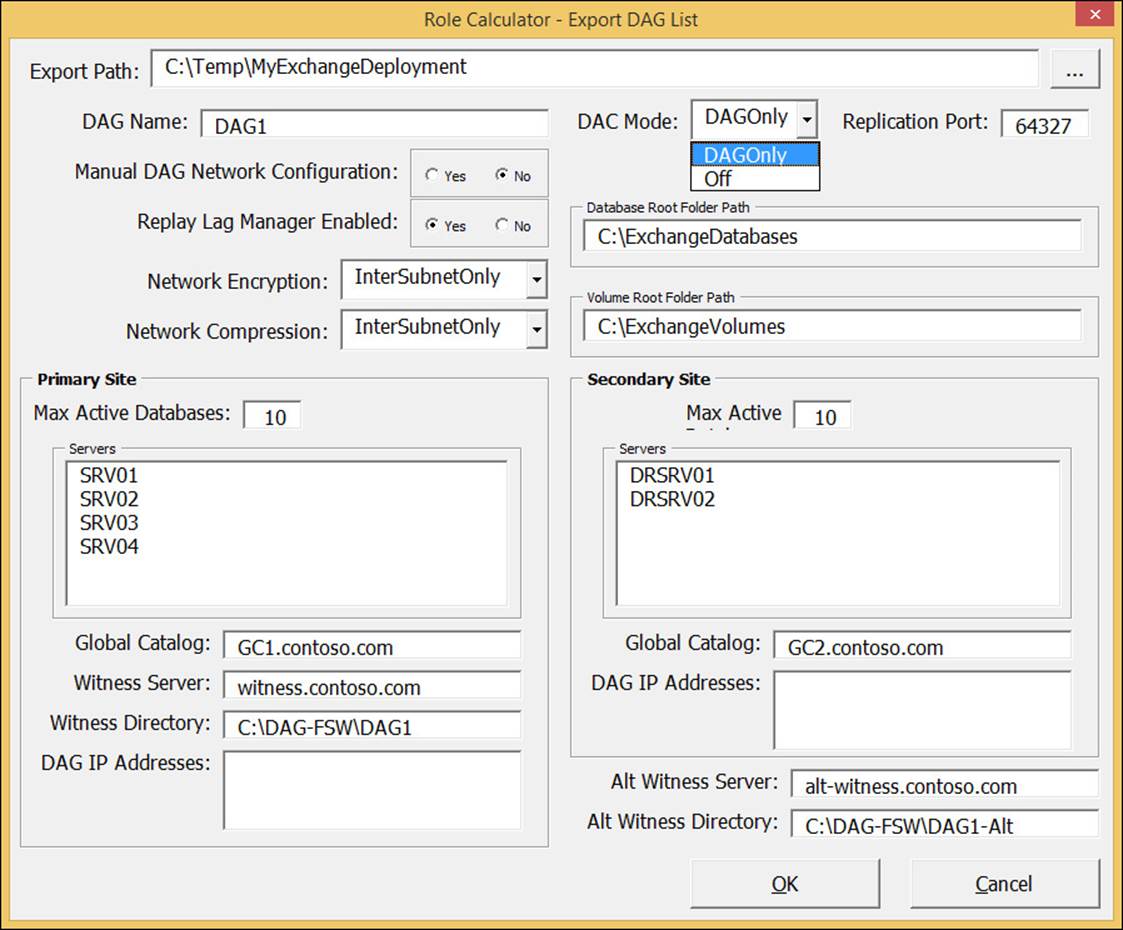
FIGURE 2-1 The Export DAG List dialog box showing the DAC Mode drop-down list with DAGOnly selected
Other scripts that can be exported from the calculator will create the databases and the database replicas for you across all of the servers in the recommended distribution.
DAC mode for DAGs with two members
In a DAG with just two members you need to take into account special considerations when enabling DAC mode because the DACP bit is not enough to protect against split-brain scenarios.
Note
You cannot enable the DatabaseActivationMode setting on DAGs that have only a single member (see Figure 2-2).
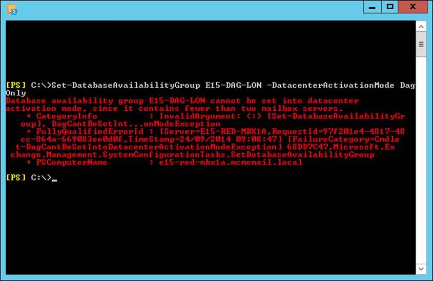
FIGURE 2-2 Error displayed when attempting to set DACMode on a single member DAG
In a DAG with only two members and DAC mode enabled, the boot time of the witness server (which would be in the same site) and the time that the DACP bit was set to 1 are compared. If the time that the DACP bit was set to 1 is earlier than the boot time of the witness server, it is assumed that all of the servers in the site were rebooted, and thus an event has occurred across the site to cause a site-wide outage.
If the DACP bit was set at a time later than the witness server’s boot time, it is assumed that the DAG member had a reboot event that was not related to a site outage.
If the reboot event is not related to a site outage (in other words, the time the DACP bit was set is later than the witness server boot time), the DAG member is allowed to mount databases.
Important: Reboot Time and Clusters
The boot time of the witness server is used to help distinguish the type of reboot event that has occurred, so you should never reboot the witness server and the sole DAG member at the same time. If they are rebooted at the same time, the sole DAG member will not be allowed to mount databases. If this happens, you need to run the Restore-DatabaseAvailabilityGroup cmdlet to reset the DACP bit and permit the DAG member to mount databases.
Other benefits of DAC mode
As well as preventing split-brain condition in a DAG, the DAC mode setting allows the use of Exchange Server cmdlets to perform datacenter switchovers. The cmdlets that can be used include the following:
![]() Stop-DatabaseAvailabilityGroup This cmdlet is used to remove a member from the DAG or to remove an entire site from a DAG; like when you need to switch service over to the secondary datacenter. This cmdlet can be run only when the DAG is configured with aDatacenterActivationMode value of DagOnly. In the event of server or site failure (rather than planned switchover), you must use the ConfigurationOnly switch to update the state of the DAG members in the Active Directory when the actual servers are unavailable.
Stop-DatabaseAvailabilityGroup This cmdlet is used to remove a member from the DAG or to remove an entire site from a DAG; like when you need to switch service over to the secondary datacenter. This cmdlet can be run only when the DAG is configured with aDatacenterActivationMode value of DagOnly. In the event of server or site failure (rather than planned switchover), you must use the ConfigurationOnly switch to update the state of the DAG members in the Active Directory when the actual servers are unavailable.
![]() Restore-DatabaseAvailabilityGroup This cmdlet brings the DAG online in a switchover event. You need to mention the site name (-ActiveDirectorySite) and optionally the alternative witness server and directory if these were not already configured as part of the DAG. In the event of a site outage, this cmdlet would be used after a failed site is removed from the DAG using Stop-DatabaseAvailabilityGroup. This cmdlet forcibly evicts from the DAG those servers on the StoppedMailboxServers list and thus resets the requirements for quorum. This allows the remaining DAG members to establish quorum, mount databases, and provide service. If there is an even number of surviving DAG members, or if there is only one surviving DAG member, then this cmdlet configures the DAG to use the alternative file share witness. A file share witness is required when the cluster has an even number of nodes (to provide a tie-breaking 3rd vote).
Restore-DatabaseAvailabilityGroup This cmdlet brings the DAG online in a switchover event. You need to mention the site name (-ActiveDirectorySite) and optionally the alternative witness server and directory if these were not already configured as part of the DAG. In the event of a site outage, this cmdlet would be used after a failed site is removed from the DAG using Stop-DatabaseAvailabilityGroup. This cmdlet forcibly evicts from the DAG those servers on the StoppedMailboxServers list and thus resets the requirements for quorum. This allows the remaining DAG members to establish quorum, mount databases, and provide service. If there is an even number of surviving DAG members, or if there is only one surviving DAG member, then this cmdlet configures the DAG to use the alternative file share witness. A file share witness is required when the cluster has an even number of nodes (to provide a tie-breaking 3rd vote).
![]() Start-DatabaseAvailabilityGroup This cmdlet is used to restore service in a recovered datacenter after the datacenter switchover to the secondary datacenter has occurred, and now the recovered datacenter is ready to take part in providing service again. After running this cmdlet, the servers that had been evicted from the cluster by the Restore-DatabaseAvailabilityGroup cmdlet can be restored to service either by bringing all of the servers in a DAG in a given site online, or by specifically mentioning the server to bring online, should not all of the servers in the site be ready and available to resume service.
Start-DatabaseAvailabilityGroup This cmdlet is used to restore service in a recovered datacenter after the datacenter switchover to the secondary datacenter has occurred, and now the recovered datacenter is ready to take part in providing service again. After running this cmdlet, the servers that had been evicted from the cluster by the Restore-DatabaseAvailabilityGroup cmdlet can be restored to service either by bringing all of the servers in a DAG in a given site online, or by specifically mentioning the server to bring online, should not all of the servers in the site be ready and available to resume service.
![]() Move-ActiveMailboxDatabase This cmdlet is used to bring the active database from one server to another. In the scenario of site recovery it would be used to move the databases that are active in the secondary datacenter back to being active in the primary datacenter. It is used to finish recovery of Exchange Server following the resumption of service in the restored primary datacenter.
Move-ActiveMailboxDatabase This cmdlet is used to bring the active database from one server to another. In the scenario of site recovery it would be used to move the databases that are active in the secondary datacenter back to being active in the primary datacenter. It is used to finish recovery of Exchange Server following the resumption of service in the restored primary datacenter.
![]() Update-MailboxDatabaseCopy This cmdlet is used to resume replication between the active and a selected passive copy after the service has been restored. Note that this cmdlet can also be used to initially seed a new database copy and is not just used when restoring service after an outage.
Update-MailboxDatabaseCopy This cmdlet is used to resume replication between the active and a selected passive copy after the service has been restored. Note that this cmdlet can also be used to initially seed a new database copy and is not just used when restoring service after an outage.
Given customer node requirements, recommend quorum options
Quorum is a feature of the cluster service in Windows Server. The cluster service is used to provide the server-up/server-down management of the Exchange Database Availability Group (DAG). At a simple level of description, the cluster nodes all communicate with each other and share a configuration that they all store, called the quorum database. One cluster member is deemed the owner of this database in the case of conflicting information in the copies of the quorum database.
Exchange Server uses a configuration of the cluster service known as Node and File Share Majority. In this configuration the quorum database is stored on all servers and replicated from the server with the writable copy of the quorum to all of the other servers in the cluster. The cluster can remain up and running and providing service if a majority of nodes of the cluster are available. The majority is calculated by taking the number of nodes in the cluster, halving this number, and adding 1 to the result. Because a DAG can have up to 16 nodes, the number of nodes in the cluster determines how many nodes need to be running for the cluster to be available for service. In the case of Exchange Server, if the cluster has majority it can mount databases and service requests to the data in the mailboxes from the other services within Exchange (such as transport and client access).
Table 2-1 shows you how many nodes need to be up in a cluster based upon the total number of nodes in the cluster. If this or more nodes are online, it is said that the cluster has majority, or it can also be said that the cluster has quorum.
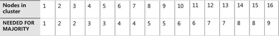
TABLE 2-1 Number of nodes that need to be up to have majority
You can see from Table 2-1 that as you increase your node count, the number of servers that you need to keep online does not increase to the same pattern. Thus if you had a DAG with three servers in it and added a fourth, you would not have increased your resilience because you could still only sustain a single node failure
The file share witness
To avoid this issue of even numbers of nodes having the same resiliency as one less server in the cluster, Exchange Server changes the quorum type depending upon the number of nodes. When you have an even number of nodes in the cluster, the cluster is running Node and File Share Majority, and when you have an odd number of nodes in the cluster, the quorum type is Node Majority.
You can see the type of quorum your DAG is running by using Get-Cluster DAGName | Get-ClusterQuorum | Format-List in PowerShell, as shown in Figure 2-3. The same figure shows the output of Get-DatabaseAvailabilityGroup E15-DAG-RED | Format-List Servers, which shows that the DAG has three nodes in it and therefore the cluster reports that it’s QuorumType is NodeMajority.
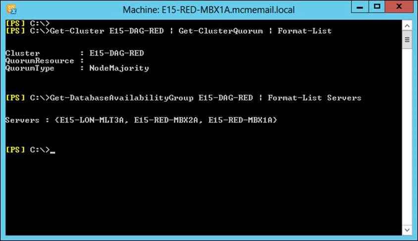
FIGURE 2-3 PowerShell output showing DAG and cluster properties
When you have an even number of Exchange Servers in the DAG, Exchange Server changes the QuorumType to NodeAndFileShareMajority, and an additional server that hosts a file share votes on the majority of the cluster. Note that the role of the file share in terms of voting only comes into play when there is not enough servers online in the cluster to provide majority on their own. Thus if you had a four node DAG and all four nodes where online, though you would be in a Node and File Share Majority cluster, you would not need the vote of the file share to see if you have quorum. If two of the servers in this four node DAG were offline or unavailable (the other side of a disconnected WAN for example), the vote of the file share witness server would come into play.
The file share witness is any Windows Server computer that can host a file share that is in the same forest as the DAG, though the recommendation is a server running the CAS role because all of the correct permissions are already in place for Exchange to create the folder, share, access, and lock a file inside the share when it needs to.
The file share witness (and an alternative file share witness in another site for when you have site failover) are set when you create the Database Availability Group. For example, the following cmdlets create a DAG called DAG1 with both the file share witness and alternative file share witness set.
// Creating a Database Availability Group and specifying all of the witness servers
New-DatabaseAvailabilityGroup DAG1 -WitnessServer FS1 -WitnessDirectory C:\DAG\DAG1
Set-DatabaseAvailabilityGroup DAG1 -AlternateWitnessServer DRFS1
-DatacenterActivationMode DagOnly
The WitnessServer and WitnessDirectory parameters are valid in the New-DatabaseAvailabilityGroup cmdlet and in the Set-DatabaseAvailabilityGroup cmdlet. The AlternateWitnessServer parameter can only be set in the Set-DatabaseAvailabilityGroup cmdlet.
You are not required to pick a witness server, and if you do not, a CAS server in the same site that you are running the New-DatabaseAvailabilityGroup cmdlet in will be selected. This CAS server, if it coexists with a mailbox role server, cannot be a member of the DAG. If you have an Exchange Server design that leads to a single DAG and co-located server roles, you need to pick your own file share that is not one of the Exchange Servers in your deployment. Exchange Server will not auto-select an alternative witness server.
Note: Choice of File Share Witness Server
Microsoft recommends that you use a client access server running on Microsoft Exchange Server 2013 in the Active Directory site containing the DAG, but not a member of the DAG. This allows the witness server and directory to remain under the control of an Exchange administrator.
If you need to pick a file server that is not an Exchange Server, you need to add the Exchange Trusted Subsystem (ETS) universal security group into the local administrators group of that server. If the file server is also a domain controller, you need to add the Exchange Trusted Subsystem universal security group into the BUILTIN\Administrators group on any domain controller in the domain, and wait for replication to complete. The Exchange Trusted Subsystem group can be found in the Microsoft Exchange Security Groups OU in the root domain of the forest.
Once the file server is selected from an available CAS, or you specify the server during the creation of the DAG,1 or when you change the DAG settings, Exchange Server creates the directory specified or uses the default directory path and shares this folder. Multiple DAGs can use the same witness server, but they must use a different path for the witness directory.
The file share witness is used when the cluster needs to determine if it has quorum and there are not enough nodes online to achieve this. The cluster name owner, or the Primary Active Manager (PAM) in the DAG, will attempt to lock a file on the file share witness. If they are able to, this counts as an additional vote, and so in the case of an even number of servers in the DAG, when half the servers are online the locking of the file share witness means the site that contains the PAM will have an additional vote. Typically this means that they will achieve majority.
Figure 2-4 shows a four node DAG across two sites. The file share witness is located in the primary site, and all four servers are up and have mounted databases.
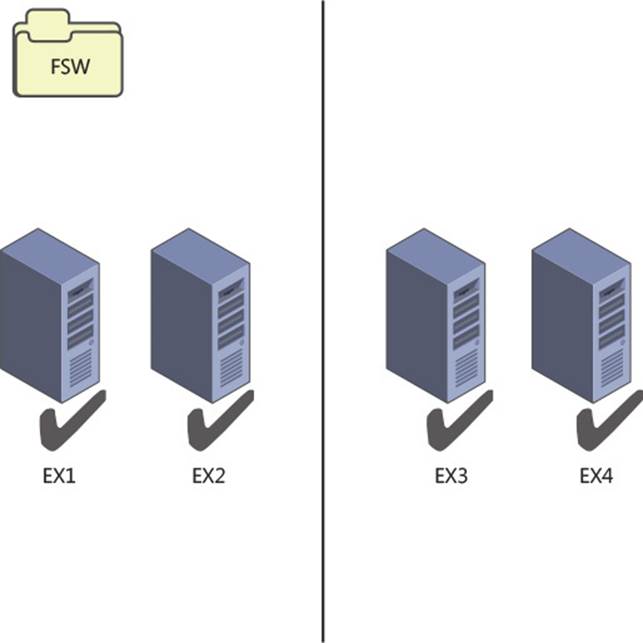
FIGURE 2-4 Four node DAG with all servers online
In Figure 2-5, the file share witness vote means that one side of the cluster can reach majority and mount databases. The other side of the DAG in the secondary datacenter cannot reach majority, and so the cluster service stops and the databases dismount.
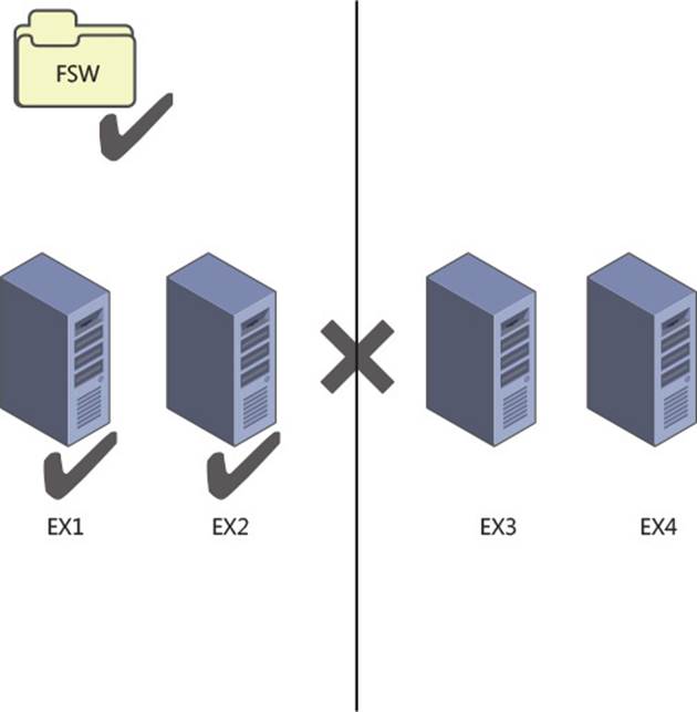
FIGURE 2-5 Four node DAG after a WAN outage
Cluster features in the operating system
Exchange Server 2013 can run on Windows Server 2008 R2, Windows Server 2012, and Windows Server 2012 R2. For the two 2012 versions of Windows Server, the Standard Edition is sufficient as this contains the failover clustering feature. For Windows Server 2008 R2, a DAG requires Enterprise Edition because the Standard Edition does not contain the failover clustering role.
 Exam Tip
Exchange Server 2013 SP1 or later is required when using Windows Server 2012 R2 as the operating system.
In Windows Server 2012, support has been added for dynamic quorum and dynamic witness. In Windows Server 2012 R2, these features are enabled by default.
Dynamic quorum is a feature where the node count for determining majority is not fixed to the number of nodes in the cluster, but the number of nodes that were online at the point of calculating quorum. In Windows Server 2008 R2, the number of nodes that are part of the quorum calculation are as described in the previous section, which means that the number of nodes for quorum equals the number of servers in the cluster. In Windows Server 2012, a cluster node loses its vote if it goes offline and regains it when it comes online. Therefore, a DAG with three nodes on Windows 2008 R2 has to have two nodes up to keep majority. The file share witness is not used because there is an odd number of nodes. But the same DAG running on Windows Server 2012 or 2012 R2 can sustain the loss of two nodes one after the other and keep majority. It does this via dynamic quorum. The loss of one server majority is recalculated and the DAG becomes a two node DAG with file share witness. That is three votes, and as long as either two nodes, or the witness server and the single DAG node are up, Exchange can keep mounting databases. Simply put, if the cluster experiences a failure that allows it to remain up and maintain quorum, then dynamic quorum can recalculate the quorum. This allows the cluster to survive additional failures and maintain quorum (more than it could without dynamic quorum). However, if your initial failure is widespread enough to cause quorum loss, the cluster will go down. So dynamic quorum really helps when you have cascading failures.
Dynamic quorum does not help in a scenario where you would lose quorum. For example, in a single site DAG with three nodes and you lose two nodes at the same time, you go from three votes (no file share witness) to one vote. One vote is not enough to maintain quorum.
This allows for a scenario called last man standing where you can progressively loose nodes and thus votes until you have one server remaining. Note that this one server might not host all of the databases or be sized to host the load of all the user connections, and so even though the cluster is up and one Exchange Server is up, not all of your databases might be up.
Important: Considering Dynamic Quorum
Do not design your DAG to take into account dynamic quorum. That means do not design every server in the DAG to hold a replica of every database, and size each server to support all of the users in the event of last man standing.
If you have two nodes left, dynamic quorum removes the vote from one node. One node will have a vote and one node will not. Use Get-ClusterNode ClusterName | Format-Table Name, DynamicWeight, State to determine which node has the vote, and do not shut that node down. If you do, the other node’s cluster service will go offline as it does not have a vote. The cmdlet will report DynamicWeight = 1 for the server that has the vote.
Quorum scenarios
Now that you have an understanding of the different scenarios where a file share witness will come into play, and that having quorum (or majority) is vital to maintaining service, we will look at some customer scenarios and best choices.
We will look at the following four scenarios:
![]() Coho Winery has two servers at their vineyard and no other locations to host offsite servers.
Coho Winery has two servers at their vineyard and no other locations to host offsite servers.
![]() Blue Yonder Airlines has a six node DAG with two of the servers in a secondary datacenter for high availability and site resiliency purposes.
Blue Yonder Airlines has a six node DAG with two of the servers in a secondary datacenter for high availability and site resiliency purposes.
![]() Northwind Electric Cars has a well-connected office and factory located in different cities with users at both locations.
Northwind Electric Cars has a well-connected office and factory located in different cities with users at both locations.
![]() Humongous Insurance has 32,000 employees and need to have automatic failover to the secondary datacenter in the event of an outage in their primary New York datacenter.
Humongous Insurance has 32,000 employees and need to have automatic failover to the secondary datacenter in the event of an outage in their primary New York datacenter.
Coho Winery single site two node This customer only has a single site but needs to ensure their email server is always available because they use it to receive orders from their suppliers. Therefore, they have a two node DAG. Their file share witness is located on their file server. They are running Windows Server 2012 R2 as their operating system for Exchange Server and so dynamic quorum comes into the equation when they need to shut down a server for maintenance, and they need to ensure they move the voting node and then keep that server online.
Blue Yonder Airlines This is a midsized regional airline company that has centralized all of its email in its head office in London. They have a disaster recovery datacenter near Oxford. They have a six node DAG supporting 4000 mailboxes with two of the nodes in the disaster recovery datacenter. All active mailbox databases are replicated to two other servers, one at the HQ for initial failover, and one at the DR site for second failover. They can lose one server and all of the mailbox databases remain on servers in the head office. At the loss of a second server in London, most mailboxes are activated on the two remaining servers in London but a small handful are activated in the secondary datacenter. The loss of two servers in London is acceptable because cross-site failover of mailbox databases is allowed. However, because they are running Exchange Server 2013 on Windows Server 2008 R2 they cannot use dynamic quorum. Therefore, because the cluster is a six-node cluster, it will make use of the file share witness. This means that with the loss of two servers in the primary site majority is maintained, or the loss of one server in the event that the WAN should also fail.
When two servers fail, but the WAN is online, there are four reachable servers. Four is a majority of six. When three servers fail, the file share witness vote becomes important because there are now three servers online (which is not a majority of six), but the extra vote from the file share witness means there are four votes. These votes are a majority, and so the cluster remains running. As long as the three failed servers are not the only servers a given database was replicated to, all mail databases remain online. If the WAN to the DR site goes offline, the two servers near Oxford will go offline (because they do not have majority). IT pros in the primary site must ensure that three Exchange Servers and the file share witness remain online while the WAN is offline.
Exchange Server Role Calculator for Exchange 2013 is a great tool for modeling these scenarios. For example, in Figure 2-6, you can see this six-server node with the WAN failed between sites (the WAN buttons reads, “Recover WAN”), and thus the two servers in the secondary datacenter are offline, and one server in the primary site has also failed. Even though Blue Yonder Airlines has lost the resources of half of their Exchange Servers, they are still able to maintain quorum and service email to their employees.
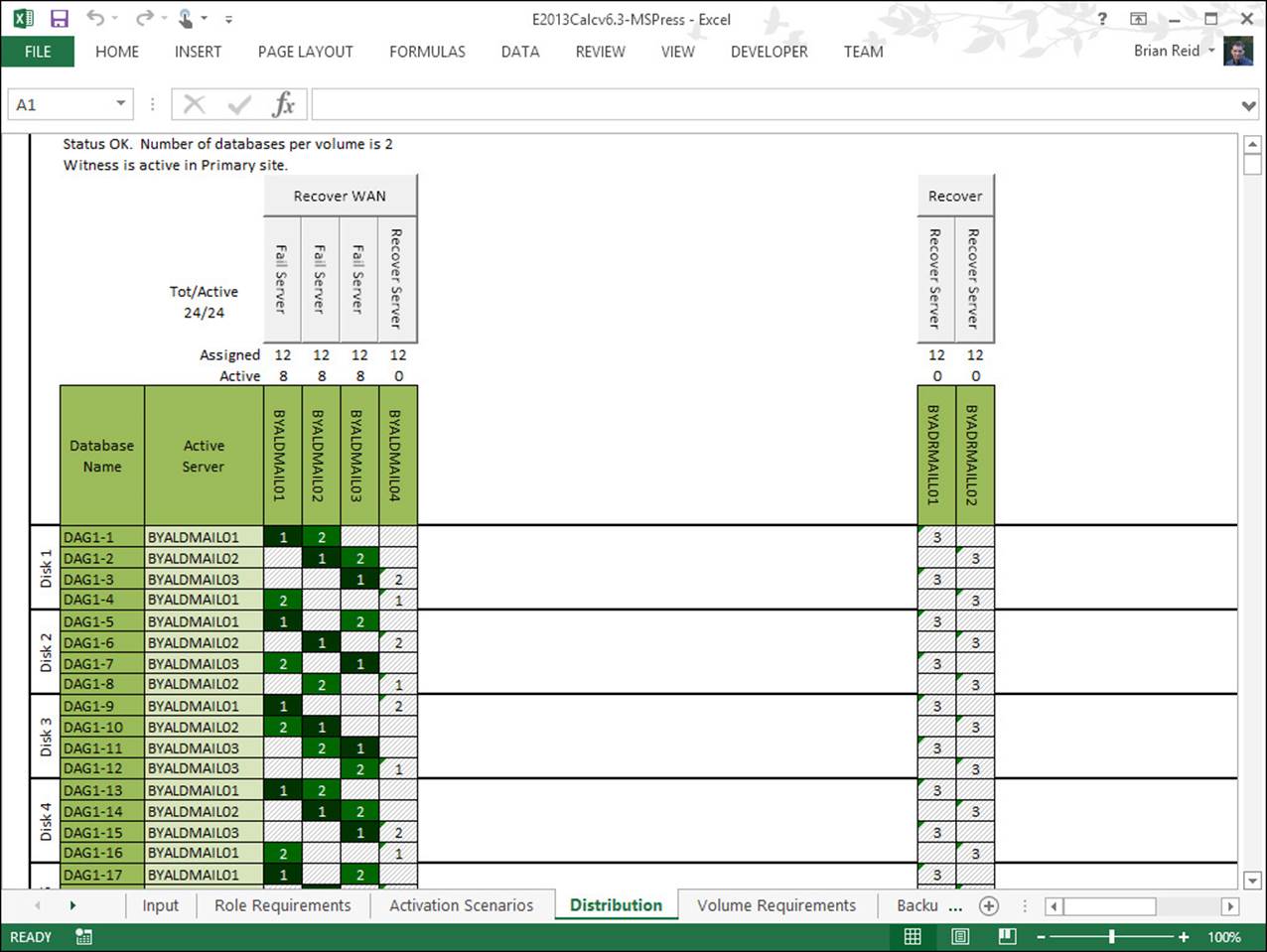
FIGURE 2-6 Exchange 2013 Storage Calculator used to model WAN and server failure scenarios
Northwind Electric Cars This customer has 2,000 staff, with 1,500 in the main office and 500 on the assembly line. There is good WAN connectivity between the sites even though they are located in different cities. Therefore they opted for two DAGs and a file share witness server located in each site (one for each DAG). The user mailboxes are located in the DAG that is in the majority at the local site. Quorum is maintained per DAG, and so each office is a separate failure domain.
If the WAN fails, the Exchange Servers that are in the secondary site for each DAG go offline. This results in some Exchange Servers in each location going offline, but because these servers are just passive copies and not used for transport shadow redundancy from the other servers in the site, there is no immediate impact to the users.
When a site fails, the mailboxes for that site could be activated in the other site if recovery of the primary site would exceed any required SLA. The other site and its servers would not be affected by the outage in the first site.
Humongous Insurance This customer is planning a migration to Exchange Server 2013 from Exchange Server 2007. As part of the migration, Humongous Insurance will make use of new technologies such as 8 TB SATA drives to reduce their storage costs in a JBOD deployment that is an eight node DAG across two datacenters. They will locate their file share witness in a third datacenter that has MPLS networking links to both the primary and secondary datacenters. Figure 2-7 shows the Distribution tab of the Exchange Server 2013 storage calculator with four servers in each site, and the file share witness in a third datacenter. The WAN in the primary datacenter has failed. The MPLS links that they have in place from the various user locations remain working, as does the link to the file share witness site and the secondary site. On the WAN failing, the secondary site can reach the file share witness and therefore is able to have five votes from a DAG of eight nodes. It is therefore able to keep majority even though the primary servers are all unreachable. The Exchange mailbox databases all mount in the secondary site automatically, and because the primary site is not able to reach the file share witness, it is only able to acquire four votes. Therefore, the cluster service in the primary datacenter does not get majority, and the databases dismount.
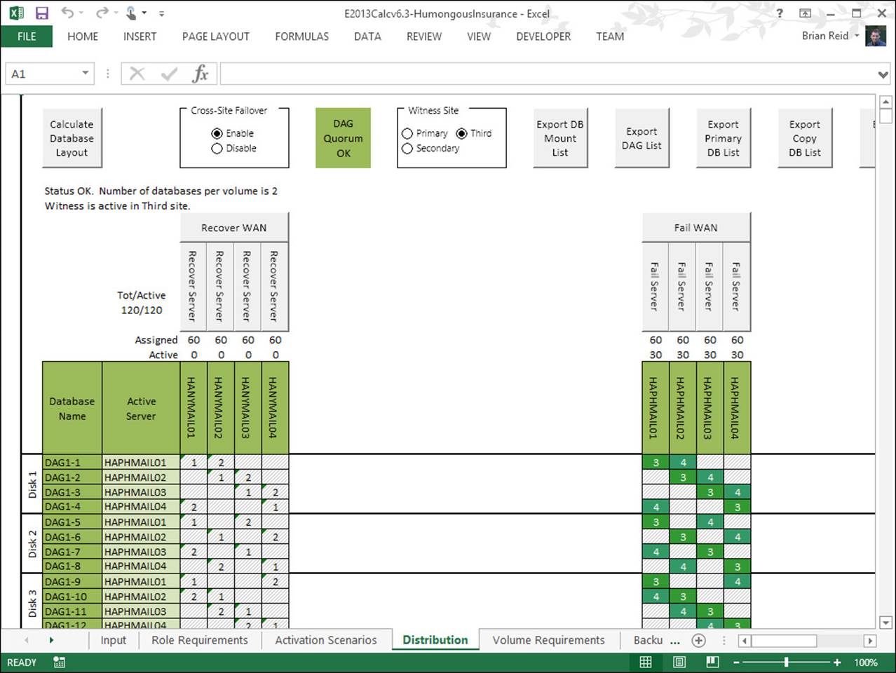
FIGURE 2-7 Modeling a WAN failure and automatic failover with a third site file share witness
Planning cross-site DAG configuration and configuring DAG networks
When you have a DAG that crosses a WAN boundary, there are a number of additional items to consider in your configuration. These are:
![]() The number of DAGs you need
The number of DAGs you need
![]() DAG IP addressing considerations
DAG IP addressing considerations
![]() Configuring DAG networks and rediscovering DAG networks
Configuring DAG networks and rediscovering DAG networks
![]() Network compression
Network compression
How many Database Availability Groups do you need?
There are a number of aspects to the question regarding the number of DAGs that you need. The most important aspect to consider is the location of your user population.
If you take a simple Exchange Server scenario like the one shown in Figure 2-8, you will see that there are users in a number of network locations. You will also see that their nearest network is Paris or Berlin, depending on their location. There are also users at each main office in Paris and Berlin. The servers are kept at the main office.
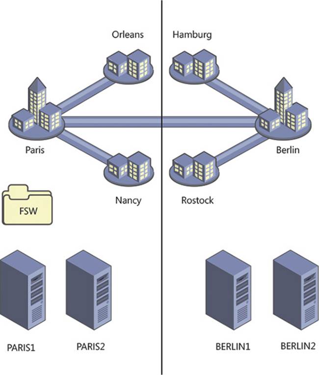
FIGURE 2-8 Exchange Server deployment in multiple offices with branch offices
In the scenario in Figure 2-8, there are users located in both Paris and Berlin. Each user connects to their mailbox which is located in the main office. If the four Exchange Servers in the scenario were placed into a single DAG, an outage of the Paris-Berlin WAN would result in all of the mailboxes being mounted in Paris because that is the location of the file share witness. This would result in a loss of access to their mailboxes for the users in Berlin, and the sites connected to it.
If the network topology for this company is such that direct connections from, for example Rostock, reached Paris by way of Berlin, then when the Paris-Berlin WAN goes offline Rostock cannot reach Paris. Even though their mailbox is online, they cannot access it from the office. Therefore, this scenario needs two DAGs. A Paris DAG with one or two servers in Paris depending upon load, sizing, and availability requirements, with a site-resilient copy in Berlin. This DAG would have a file share witness in Paris and a Berlin-homed DAG with the file share witness in Berlin. When the WAN fails, the Paris DAG will mount its databases in Paris, and the Berlin DAG will mount its databases in Berlin. This is known as an Active/Active (Multiple DAG) model and can be seen in Figure 2-9. This model avoids the WAN link between the two sites being a potential single point of failure, though it does require more servers than a single DAG for the same user count and mailbox size. If the WAN can be a resilient WAN, an Active/Active (Single DAG) model can be deployed where there are active mailbox databases mounted in each site. Because the WAN is resilient, an outage of part of the WAN results in an alternative route being used, and the mailbox databases staying online in their desired locations.
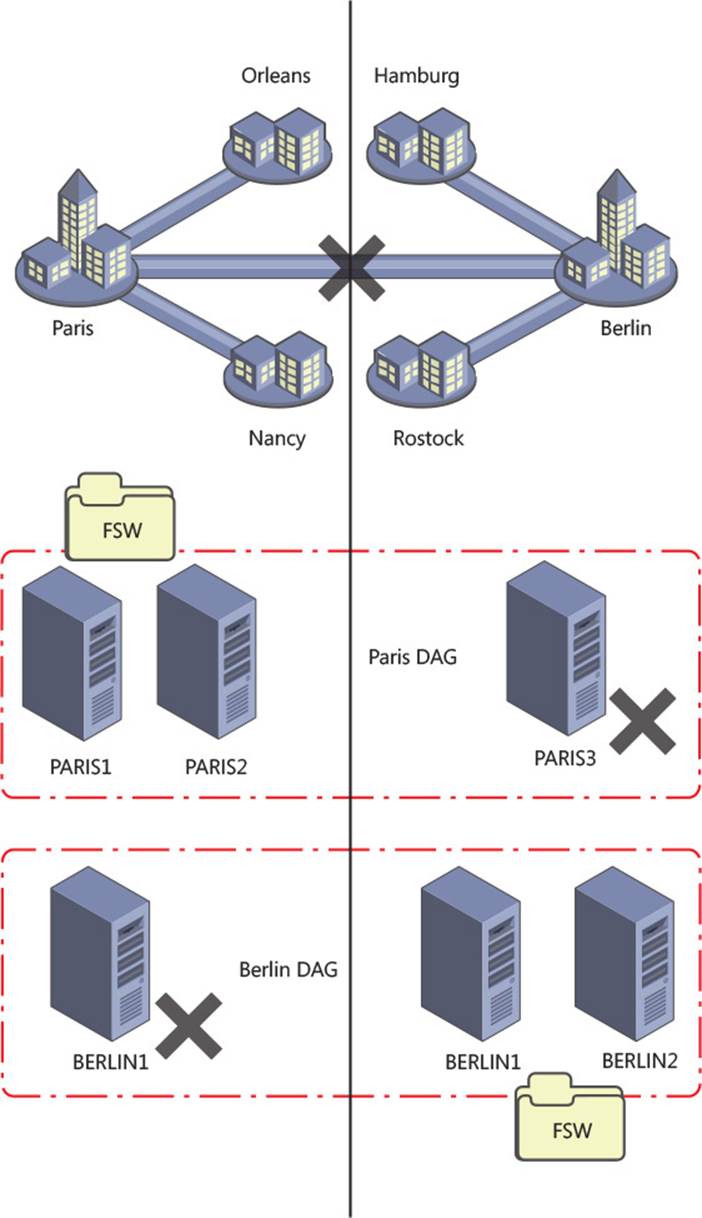
FIGURE 2-9 A two datacenter design where users are located at or networked to each datacenter
DAG IP addressing considerations
In a Windows Server 2008 R2 or Windows Server 2012 cluster, you need to have an IP address assigned to the DAG for each site that the DAG can operate in. You can either assign an IP address manually when creating the DAG in Exchange Management Shell, or allow DHCP to assign an IP address to the DAG. For auto assignment of IP addresses, you obviously need to have a DHCP server running in each site that the DAG is in, and available IP addresses at the time of failover. If you do not have a DHCP server or servers that can supply IP addresses to each site, or you cannot guarantee available IP addresses in the DHCP pool when failover occurs, you should manually assign a valid IP address for each site and ensure that nothing else uses that address by removing it from the DHCP pool or updating your documentation on available addresses.
In a Windows Server 2012 R2 cluster with Exchange Server 2013 SP1 or later, you can create a DAG that does not have an underlying cluster name or IP address requirement. This is known as a DAG without a cluster administrative access point. DAGs without administrative access points have the following features:
![]() There is no IP address assigned to the cluster/DAG, and therefore no IP address resource in the cluster core resource group.
There is no IP address assigned to the cluster/DAG, and therefore no IP address resource in the cluster core resource group.
![]() There is no network name assigned to the cluster, and therefore no network name resource in the cluster core resource group
There is no network name assigned to the cluster, and therefore no network name resource in the cluster core resource group
![]() The name of the cluster/DAG is not registered in DNS, and it is not resolvable on the network.
The name of the cluster/DAG is not registered in DNS, and it is not resolvable on the network.
![]() It is not required to pre-create the cluster name object (CNO) in the Active Directory.
It is not required to pre-create the cluster name object (CNO) in the Active Directory.
![]() The cluster cannot be managed using the Failover Cluster Management tool. It must be managed using Windows PowerShell, and the PowerShell cmdlets must be run against individual cluster members.
The cluster cannot be managed using the Failover Cluster Management tool. It must be managed using Windows PowerShell, and the PowerShell cmdlets must be run against individual cluster members.
![]() There is no computer object that needs to be created in the Active Directory for the cluster. This avoids a series of administrative tasks and removes potential issues if the object is accidently deleted.
There is no computer object that needs to be created in the Active Directory for the cluster. This avoids a series of administrative tasks and removes potential issues if the object is accidently deleted.
Each of these features will impact the way you interact with the cluster, most notably in terms of the management tools used. But the features that remove the need for a network name (CNO) and IP address reduce the resources required by the cluster service, and therefore reduce the items that if they fail will cause the cluster to failover or go offline.
To create a DAG without an administrative access point, use the following in the Exchange Management Shell.
New-DatabaseAvailabilityGroup -Name DAG1 -WitnessServer EX4
-DatabaseAvailabilityGroupIPAddresses ([System.Net.IPAddress])::None
Important: Backup Software Considerations
Some third-party backup software that connects to the cluster using the DAG name will not work with a DAG that has been created without an administrative access point.
Configuring DAG networks and rediscovering DAG networks
The cluster that underlies the DAG requires at least one network that all the nodes share and that the clients of the DAG can use to reach the mailbox databases. Optionally you can have a second network in the cluster that Exchange will use for transaction log replication. Clients do not connect to the DAG via the replication network and so it is dedicated to the role of replicating transaction logs as fast as the network will allow.
It is important to consider if you need a replication network at all. In a cross-site DAG, the most likely configuration for the WAN between the sites is that you have a single WAN. Therefore, all cross-site communication is on this single connection even though you have two network cards in each server. Splitting the client and replication traffic onto separate networks in the LAN at each end, only to combine them on the WAN, means that in reality you have a single network that the replication traffic will cross.
If you do have two WAN links, a large enough user population, or dedicated network switching and trunking such that you really can take the replication traffic off of the network that the clients are on, then it is worth doing. For smaller networks or networks with capacity beyond their requirements and sufficient switching capacity, it is probably easier to keep the administration of Exchange Server simple, and keep to a single client and replication network.
If you have a second network for replication, it must be configured correctly. For Exchange Server this network should be configured as follows:
![]() Not registered in DNS It is not reachable by clients, and so clients should not resolve this server on this network. This setting can be seen in Figure 2-10.
Not registered in DNS It is not reachable by clients, and so clients should not resolve this server on this network. This setting can be seen in Figure 2-10.
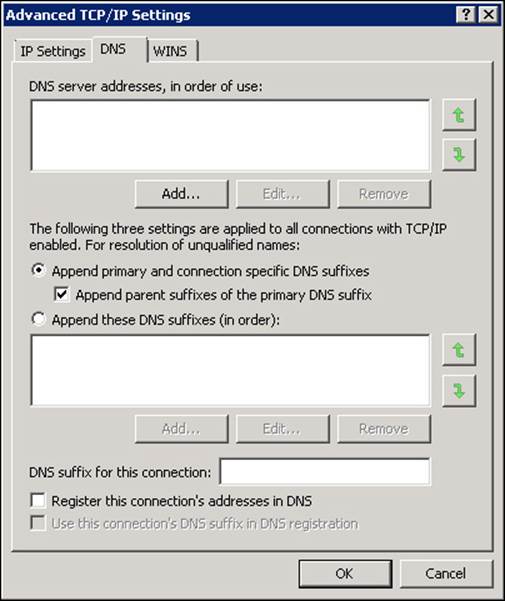
FIGURE 2-10 DNS settings for the replication network
![]() Not having a default gateway You should have one default gateway on the server and this should be on the network card that all unknown routes use (the client network in our example). The replication network should have manual routes configured so that you can reach the replication network in the other sites.
Not having a default gateway You should have one default gateway on the server and this should be on the network card that all unknown routes use (the client network in our example). The replication network should have manual routes configured so that you can reach the replication network in the other sites.
![]() The client or MAPI network is listed above the replication network in the network binding order The binding order can be changed from the Network Connections window. Press ALT to see the menu and then choose Advanced, and Advanced Settings. The Advanced Settings dialog box is shown in Figure 2-11. Note that Microsoft recommends that IPv6 is not disabled (see http://support.microsoft.com/kb/929852).
The client or MAPI network is listed above the replication network in the network binding order The binding order can be changed from the Network Connections window. Press ALT to see the menu and then choose Advanced, and Advanced Settings. The Advanced Settings dialog box is shown in Figure 2-11. Note that Microsoft recommends that IPv6 is not disabled (see http://support.microsoft.com/kb/929852).
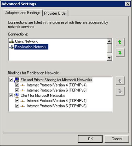
FIGURE 2-11 Setting the network binding correctly for a dedicated replication network
If you get the network card and client/replication network configuration correct, Exchange Server 2013 will auto-configure your DAG networks for you. The DAG networks are a configuration that helps Exchange understand how the network is configured. They are not physical networks or settings on the network card.
If your Exchange Servers have networks other than those that will be used for clients and replication, you will need to disable them in the DAG network. Examples include management networks and backup networks. If you have these additional networks you have to manually configure your DAG networks and then use the -ignorenetwork $true parameter in Exchange Management Shell to mark the network as not to be used by the DAG.
Network compression
When a DAG is created, Exchange Server will by default compress network traffic between the nodes when they go cross-site, but by default network traffic is not compressed within the site. Compression takes a little additional CPU to complete at each end, but reduces the traffic considerably. In places where you have limited bandwidth the extra CPU impact is acceptable as you usually have capacity, whereas you might not have capacity on the WAN.
There is typically not much point enabling compression on a LAN as the capacity is available for uncompressed traffic.
Compression is set as a property of the DAG and not the underlying DAG network. To check the compression of your DAG, use the following Exchange Management Shell cmdlet.
Get-DatabaseAvailabilityGroup E15-DAG-RED | Format-List NetworkCompression
The possible values for network compression are:
![]() Disabled All intra-DAG traffic is not compressed regardless of DAG node location.
Disabled All intra-DAG traffic is not compressed regardless of DAG node location.
![]() Enabled All intra-DAG traffic, including replication and database seeding is compressed.
Enabled All intra-DAG traffic, including replication and database seeding is compressed.
![]() InterSubnetOnly All DAG replication traffic (not seeding traffic) is replicated between subnets. Replication within the LAN is not compressed.
InterSubnetOnly All DAG replication traffic (not seeding traffic) is replicated between subnets. Replication within the LAN is not compressed.
![]() SeedOnly Only database seeding traffic is compressed.
SeedOnly Only database seeding traffic is compressed.
Compression generates a saving of about 30 percent over uncompressed traffic and should be used inter-subnet unless you have WAN optimizers that can do a better job. Given that all of the traffic is typically unique, WAN optimizers are unlikely to achieve this and should be turned off for traffic on the replication port of TCP 64327.
Note: Changing the TCP port
The replication port of TCP 64327 can be changed. If it is, firewalls on the Exchange Server need to be updated to allow the new port and network inspection devices should be configured to ignore the traffic on this new port.
Creating a DAG on Windows Server 2012 and 2012 R2 Servers
A cluster name object (CNO) is automatically created in the Active Directory by cluster service on Windows Server 2008 R2 when the DAG is created. This does not happen automatically on Windows Server 2012 or 2012 R2 and needs to be created manually. If you are making a DAG without an administrative access point, you do not need to pre-create a CNO because this type of DAG does not need one.
More Info: Pre-Staging the Cluster Name Object
For instructions on pre-staging the cluster name object see http://technet.microsoft.com/en-gb/library/ff367878(v=exchg.150).aspx. There are scripts available online to do this for you as well, such as this one http://eightwone.com/2012/12/20/cluster-name-object-pre-staging/ by Exchange Server MVP Michel de Rooij.
 Thought experiment: Patching Exchange Servers
In this thought experiment, apply what you’ve learned about this objective. You can find answers to these questions in the “Answers” section at the end of this chapter.
1. You are the network administrator of Fabrikam Inc and you have six Exchange 2013 SP1 servers distributed across two sites. Your operating system is Windows Server 2012 R2. There are four servers in your primary site and two servers in the disaster recovery site. DAG Mode is set to DAGOnly. Your file share witness is located in the primary site. Each database has four copies and is therefore replicated three times from the active copy. This replication is twice in the primary site and once more to the DR site.
2. How many servers can you switch off at a given time and ensure quorum is maintained and service stays online for users? Cross-site failover of databases is allowed.
3. In the event of a WAN outage, what does the maximum number of servers that you can patch at a single time reduce to?
Objective summary
![]() Datacenter Activation Coordination (or the DatacenterActivationMode parameter) is recommended when you have more than two servers in the DAG.
Datacenter Activation Coordination (or the DatacenterActivationMode parameter) is recommended when you have more than two servers in the DAG.
![]() Ensure that you understand that two servers in a DAG should still have Datacenter Activation Coordination enabled, but be aware of the implications of restarting the file share witness at the same time as restarting a DAG member.
Ensure that you understand that two servers in a DAG should still have Datacenter Activation Coordination enabled, but be aware of the implications of restarting the file share witness at the same time as restarting a DAG member.
![]() DAC mode allows you to use the Exchange cmdlets only to switch or failover to a secondary datacenter and to switch back again upon resumption of service without the risk of split-brain condition occurring in the cluster.
DAC mode allows you to use the Exchange cmdlets only to switch or failover to a secondary datacenter and to switch back again upon resumption of service without the risk of split-brain condition occurring in the cluster.
![]() Quorum is both the database in the cluster that stores the cluster settings (it is the cluster hive in the registry), and a term that indicates that the cluster has majority.
Quorum is both the database in the cluster that stores the cluster settings (it is the cluster hive in the registry), and a term that indicates that the cluster has majority.
![]() Exchange Server manages the cluster type, changing it from NodeMajority to NodeAndFileShareMajority depending upon the number of servers in the cluster. NodeAndFileShareMajority is used when the cluster has an even number of nodes.
Exchange Server manages the cluster type, changing it from NodeMajority to NodeAndFileShareMajority depending upon the number of servers in the cluster. NodeAndFileShareMajority is used when the cluster has an even number of nodes.
![]() The file share witness is used to provide an extra vote to determine quorum in the event that only half of the nodes are reachable in an even numbered cluster. The file share witness contains a file called Witness.log that one Exchange Server, the Primary Active Manager (PAM), which is the server that owns the cluster resources, attempts to lock to ensure majority. Therefore, ensure that the PAM and the file share witness are both located in the primary site unless the witness server is in a third site.
The file share witness is used to provide an extra vote to determine quorum in the event that only half of the nodes are reachable in an even numbered cluster. The file share witness contains a file called Witness.log that one Exchange Server, the Primary Active Manager (PAM), which is the server that owns the cluster resources, attempts to lock to ensure majority. Therefore, ensure that the PAM and the file share witness are both located in the primary site unless the witness server is in a third site.
![]() It is recommended to keep your Exchange Server deployment simple as that reduces the risk of human error from causing a site or server outage. Therefore a single network for DAG replication and client traffic is recommended.
It is recommended to keep your Exchange Server deployment simple as that reduces the risk of human error from causing a site or server outage. Therefore a single network for DAG replication and client traffic is recommended.
Objective review
Answer the following questions to test your knowledge of the information in this objective. You can find the answers to these questions and explanations of why each answer choice is correct or incorrect in the “Answers” section at the end of this chapter.
1. One winter’s day a supplier-level power failure occurs impacting the primary site. Staff are sent home and your requirement is to bring Exchange Server online in the disaster recovery site. What are the steps to do this when the file share witness is located in the primary site and DatacenterActivationMode is set to DAGOnly? The alternative witness server had been configured when the DAG was originally set up.
A. Stop-DatabaseAvailabilityGroup -ActiveDirectorySite <PrimarySite> followed by Resume-DatabaseAvailabilityGroup -ActiveDirectorySite <SecondarySite>
B. Stop-DatabaseAvailabilityGroup -ActiveDirectorySite <PrimarySite> followed by Start-DatabaseAvailabilityGroup -ActiveDirectorySite <SecondarySite> -WitnessServer FS1
C. Stop-DatabaseAvailabilityGroup -ActiveDirectorySite <PrimarySite> followed by Restore-DatabaseAvailabilityGroup -ActiveDirectorySite <SecondarySite>
D. Stop-DatabaseAvailabilityGroup -ActiveDirectorySite <PrimarySite> followed by Restore-DatabaseAvailabilityGroup -ActiveDirectorySite <SecondarySite> -WitnessServer FS1
2. You need to design a DAG layout for a company with 5000 staff located around the world. The company has three datacenters, one located in San Francisco, one in Madrid, and one in Tokyo. Mailbox sizes mean that one server in each site is sufficient to store the data and a second server is needed for high availability. The network infrastructure of the company allows all users to access all parts of the network via an MPLS cloud network, but the fastest links are to the geographically closest datacenter. If the MPLS network links fail, cross-site connectivity will be broken. What will this Database Availability Group (or groups) configuration look like to ensure a working solution in both active and failure scenarios?
A. Create a single DAG with two servers in each datacenter as members of this DAG with the file share witness in Madrid.
B. Create two DAGs, one with the PAM and file share witness in San Francisco and the other with the PAM and FSW in Tokyo. Add one server in Madrid to the San Francisco DAG, and the other server to the Tokyo DAG.
C. Create three DAGs, one for each datacenter and expand the DAG to the nearest other datacenter where an additional server will be placed for site resilience for that primary datacenter of the DAG.
D. Create four DAGs. One in each datacenter with two servers in it, and then a fourth DAG that holds the replica servers and is distributed geographically across all of the datacenters.
Objective 2.2: Design, deploy, and manage a site-resilient CAS solution
As well as ensuring that your databases are resilient across different mailbox servers, it is also important to ensure that the client access layer is redundantly available as well. Clients all connect to their mailbox layer via the client access server (CAS) layer. Unlike earlier versions of Exchange Server, there is no client connectivity direct to the mailbox database.
This objective covers how to:
![]() Plan site-resilient namespaces
Plan site-resilient namespaces
![]() Configure site-resilient namespace URLs
Configure site-resilient namespace URLs
![]() Perform steps for site rollover
Perform steps for site rollover
![]() Plan certificate requirements for site failovers
Plan certificate requirements for site failovers
![]() Predict client behavior during a rollover
Predict client behavior during a rollover
Planning site-resilient namespaces
In Exchange Server 2010, failover to a second site of the client access layer involved a change in the namespace. The namespace is what users and clients need to connect to Exchange to reach their mailboxes. For example, mail.contoso.com would be a namespace for the Contoso Pharmaceuticals email service and dr-mail.contoso.com might be a namespace needed when mailboxes are moved to the DR site. If you used protocol specific namespaces such as smtp.contoso.com for transport and owa.contoso.com then you would need disaster recovery/second datacenter versions of the primary URLs as well.
In the event of a full site failover, it is possible to update DNS and move the entire namespace to the secondary site. But while some databases are on the primary site and others on the secondary site, and the client access layer is operational at both sites. This meant that in Exchange 2010 you needed two namespaces. The primary driver for this was that connectivity between the CAS layer and the mailbox databases was RPC based which required a fast network with low latency between the tiers and so performance issues could occur if the CAS tier was in a separate site from the mailbox database. That is, your mailbox was on a database in the secondary datacenter but you were using a CAS server at the primary datacenter. In Exchange 2010, cross-site access could be disabled and then CAS connectivity would failover to the remote site, but a namespace change would occur.
In Exchange 2013, all connectivity between Exchange Servers has been moved to the HTTP protocol (and SMTP for transport, and IMAP or POP3 if using an older client). There is no cross-server RPC connectivity. This means that the client connection is ultimately made to the server that contains the active mailbox database for that user’s mailbox and that all connectivity happens to and from that server. Exchange Server 2013 provides a proxy layer, known as the CAS role. This proxy layer ensures that user connections are made to the correct mailbox server. Therefore a user or client can connect to any CAS role server, authenticate to prove who they are, and then the CAS role proxies their connections to the mailbox role server that holds their active mailbox database. This is shown in Figure 2-12.
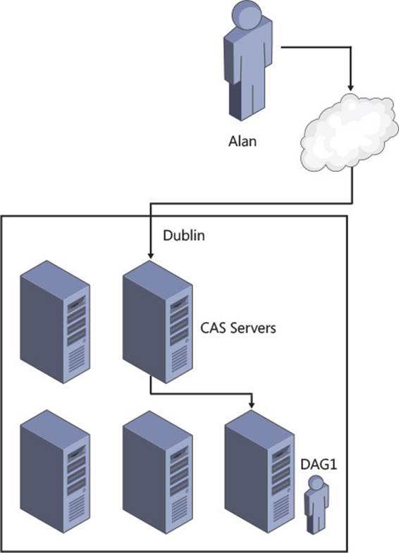
FIGURE 2-12 CAS proxy to active mailbox database
In Figure 2-12, it does not matter if the user connects to either of the two CAS servers shown because both of them will proxy the user to the same mailbox server, the one that is active for their mailbox.
Real World: Multiple CAS Roles and Mailbox Roles
Though Figures 2-12 and 2-13 show the CAS role and the mailbox role as installed on separate servers, this is for the purpose of illustration only. Microsoft recommends that you use multi-role installations.
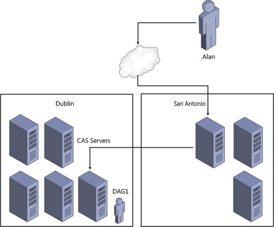
FIGURE 2-13 Single namespace design with multiple datacenters
Consider Figure 2-12 in real life. This would require five Exchange Server and Windows Server licenses as well as the hardware or virtual resources to run this configuration. If the company requires three mailbox servers, installing CAS and mailbox on three servers reduces the license count, reduces the hardware or virtual resources, reduces the servers to manage, and increases the high availability of the CAS role from two servers to three, all at a cost saving both for deployment and ongoing running costs.
When Exchange Server 2013 is installed into more than one datacenter, and some or all of these datacenters have an inbound Internet connection, it is possible to use different technologies to direct the user at a specific datacenter. For example, this could be a technology that routes the user’s connection to their geographically closest datacenter rather than the datacenter that holds their active mailbox.
The Exchange CAS layer will then direct the traffic using the same protocol that the user connected with, and which is a protocol that is capable of dealing with lower latency links, i.e. HTTP, to the mailbox server that is active for that user’s mailbox.
This can be seen in Figure 2-13, which is an expansion of the network shown in Figure 2-12. If in this figure the user has a mailbox in Ireland but was travelling in the United States (US), they would be directed to the San Antonio datacenter as that is closer to them over the Internet. When on the private network of the company, the endpoint the user has connected to in San Antonio is then connected to the location of the mailbox server in Dublin. The user receives fast Internet connectivity rather than a high latency connection to another part of the world over the public Internet, and the performance they see from Exchange Server is quick. This is similar to the model that Office 365 uses with the Exchange Online service, and importantly for namespace simplicity, allows the user to use a single namespace regardless of their location or the location of their mailbox. In this example, if this was Contoso, all users throughout the world would use mail.contoso.com to access Exchange Server.
More Info: Using the Lab Environment
MVP Paul Cunningham has written a blog post at http://exchangeserverpro.com/exchange-2013-client-access-server-high-availability/ which shows how to configure the Outlook Anywhere namespace for high availability and quick failover times in a lab environment using DNS round robin.
This is an excellent scenario to test in a lab as it introduces you to the concepts of load balancing without the layout of a load balancer, though for real world experience we recommend downloading a trial virtual load balancer from one of the vendors listed athttp://technet.microsoft.com/en-us/office/dn756394.
In past examples, we have used both bound and unbound namespace models. A bound namespace is where the name is specifically targeted to a single datacenter and an unbound model is where the namespace works regardless of which datacenter you connect to.
Configuring site-resilient namespace URLs
Once you have decided upon the type of namespace that you will have with Exchange Server 2013, and the domain name that you will use for the namespace, you need to configure the InternalURL and ExternalURL of a series of web services and the hostname value for Outlook Anywhere. These URLs and hostnames will direct clients to the correct servers by the client resolving that server via DNS.
The majority of clients obtain their settings via the AutoDiscover service. This service returns to the client the InternalURL and ExternalURL for each web service, and the hostnames for Outlook Anywhere based on the site that the user’s mailbox is active in. The Autodiscover namespace is the first namespace value that you need for Exchange. The Autodiscover namespace is always the SMTP domain name (such as contoso.com) or Autodiscover and then the SMTP domain name (for example autodiscover.contoso.com). This namespace is unbound, that means it is the same regardless of where users are located. It only changes where you have more than one SMTP namespace (for example contoso.com and contoso.co.uk), and then Autodiscover is based upon the user’s SMTP domain in their email address.
If you want your users to connect through a single namespace, such as mail.contoso.com for all Internet facing sites as described above, then every web service in Exchange Server will have the same URL regardless of site. If you take a look at the example in Figure 2-14, you can see that though there are three sites, two of which are accessible via the Internet, the URL used for each service in each site will be mail.contoso.com.
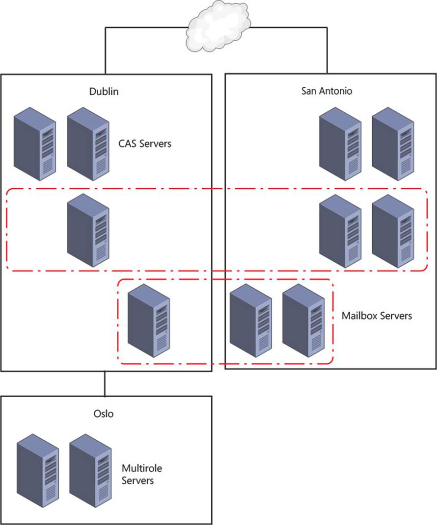
FIGURE 2-14 Setting URLs based on namespace design
For the URLs in a single namespace model, as shown in Figure 2-14, it does not matter if an ExternalURL is set for each service in Oslo, as the namespace is the same in all sites. If Figure 2-14 represented a company with multiple namespaces, the following could be an example that would be needed for the ExternalURLs
![]() Dublin: ie-mail.contoso.com
Dublin: ie-mail.contoso.com
![]() San Antonio: us-mail.contoso.com
San Antonio: us-mail.contoso.com
![]() Oslo: No external namespace
Oslo: No external namespace
In the event of a failover, the single namespace model would require no additional configuration as a device such as a geo load-balancer or IP AnyCast would direct traffic to any working datacenter. The working datacenter is either capable of hosting mailbox databases from the DAG that was active in the failed datacenter, or being able to reach the datacenter that is hosting the databases.
In the event of a failure with a bound namespace model, where different URLs are bound to servers per datacenter, things work differently. If have an outage in Dublin (based on Figure 2-14), and ie-mail.contoso.com namespace becomes unreachable, you will need to either wait for the outage to resolve itself. Alternatively you could manually update DNS to point ie-mail.contoso.com to the same IP address as us-mail.contoso.com. Connections will now either connect back to Dublin over the WAN (if it is still up and it was an Internet connection outage only), or you will need to failover the databases to the DAG’s secondary datacenter in San Antonio. Of course technology like DNS-based geo-load balancing can be used to swap the DNS records to the working datacenter for you rather than doing it manually.
Setting the namespace URLs in Exchange Server
The steps to configure the site resilient namespace are to set the ExternalURL for the following services using either ECP or Exchange Management Shell:
![]() Outlook Web App https://mail.contoso.com/owa
Outlook Web App https://mail.contoso.com/owa
![]() Exchange Control Panel https://mail.contoso.com/ecp
Exchange Control Panel https://mail.contoso.com/ecp
![]() Outlook Address Book https://mail.contoso.com/OAB
Outlook Address Book https://mail.contoso.com/OAB
![]() ActiveSync https://mail.contoso.com/Microsoft-Server-ActiveSync
ActiveSync https://mail.contoso.com/Microsoft-Server-ActiveSync
![]() Exchange Web Services https://mail.contoso.com/ews/exchange.asmx
Exchange Web Services https://mail.contoso.com/ews/exchange.asmx
![]() Outlook Anywhere mail.contoso.com (note that this is the ExternalHostname property and not ExternalURL)
Outlook Anywhere mail.contoso.com (note that this is the ExternalHostname property and not ExternalURL)
In sites that are not Internet connected, such as Oslo in Figure 2-14, you need to leave the ExternalURL blank (or set it to $null). The InternalURL is often set the same as the ExternalURL because that makes connectivity for users easier to manage, regardless of where the user is, if the URL is the same. If the InternalURL is different it should be set the same for every server in the site.
 Exam Tip
By default the InternalURL is the server’s FQDN and the ExternalURL is null. For Outlook Anywhere the InternalHostname is the server’s FQDN and the ExternalHostname is null.
All of the servers in a site should have the same value for the URLs and hostname for a given protocol or service.
An example of setting the Outlook Web App URL for the multi-namespace example in Figure 2-14 is as follows.
Set-OwaVirtualDirectory <ServerNameInDublin> -InternalUrl https://ie-mail.contoso.com/
owa -ExternalUrl https://ie-mail.contoso.com/owa
Set-OwaVirtualDirectory <ServerNameInSanAntonio> -InternalUrl https://us-mail.contoso.
com/owa -ExternalUrl https://us-mail.contoso.com/owa
Set-OwaVirtualDirectory <ServerNameInOslo> -InternalUrl https://mail.contoso.no/owa
-ExternalUrl $null
Note: Protocol Specific Load Balancing
With a layer 7 load balancer in front of Exchange Server, it is possible to use protocol specific URLs. When a protocol fails, the load balancer will automatically connect you to a different server for just that protocol. You can find out more how URLs such ashttps://owa.contoso.com/owa and https://phone.contoso.com/microsoft-server-activesync can work at http://blogs.technet.com/b/exchange/archive/2014/03/05/load-balancing-in-exchange-2013.aspx.
Performing steps for site rollover
In the event of a site outage, the steps that you need to take to failover the DAG depend upon the type of namespace model you have in place, as well as other technologies such as Anycast DNS or geo-load balancing. For simplicity, these steps assume that technologies such as those mentioned are not in use, and manual DNS changes will need to be made.
1. Failover mailbox databases to the secondary site. This involves Stop-DatabaseAvailabilityGroup and Restore-DatabaseAvailabilityGroup if using DAC Mode as a multi-site DAG should be (though it is not the default).
2. Changing DNS both internally and externally to point to the IP associated with the load balancer virtual IP in the secondary datacenter.
Planning certificate requirements for site failovers
As Exchange 2013 uses Internet protocols for all client connectivity, every name used by Exchange Server in client connectivity should be listed on a single digital certificate. This means that a certificate used by Exchange should include autodiscover.domain.com. It should also include the namespace used for the primary site, as well as each protocol if using protocol independent namespaces and the secondary site namespaces.
The same certificate should be used on all servers because the HTTP authentication cookie that CAS generates when the user first logins is generated using the certificate on the server. When the load balancer directs that user connection to a different CAS server, as stateful connections are not required, the authentication cookie can be read as the same digital certificate is installed, and so the user is not required to authenticate again. Also, digital certificates are not licensed per server, and so the purchase of one certificate can be exported, with the private key, from the machine it is created on. It can then be imported onto all of the other Exchange CAS servers. Any Exchange mailbox only server role can use the self-generated certificate because clients do not connect directly to the mailbox role services. The same is true of certificates on the Exchange Back End website on a multi-role server as this website correlates to the mailbox server role. Whereas, the Default Web Site correlates to the CAS role and will require a trusted certificate bound to it.
Therefore, if you have a network such as that shown in Figure 2-15, you would generate the following certificate:
![]() autodiscover.contoso.com
autodiscover.contoso.com
![]() newyork.contoso.com
newyork.contoso.com
![]() dallas.contoso.com
dallas.contoso.com
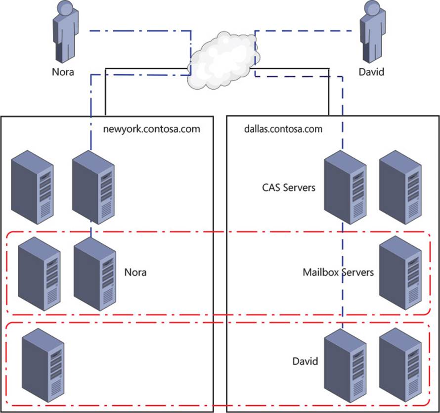
FIGURE 2-15 A bound namespace model with multiple datacenters and sites where users connect to their local namespace
Compare the above with a network that supports a single namespace and a file share witness in a third site. This would need a certificate with either:
![]() autodiscover.contoso.com
autodiscover.contoso.com
![]() mail.contoso.com
mail.contoso.com
Or, if using per-protocol load balancer checks:
![]() autodiscover.contoso.com
autodiscover.contoso.com
![]() mail.contoso.com
mail.contoso.com
![]() ecp.contoso.com
ecp.contoso.com
![]() oa.contoso.com
oa.contoso.com
![]() eas.contoso.com
eas.contoso.com
![]() oab.contoso.com
oab.contoso.com
![]() mapi.contoso.com
mapi.contoso.com
![]() ews.contoso.com
ews.contoso.com
Predicting client behavior during a rollover
The exact behavior of any given client during planned switchover or unexpected failover can be determined by valid testing of the client. This testing should take into consideration the firmware or software version of the client because different products and versions will respond in different ways (specifically ActiveSync clients).
Let us consider some points of interest that will help predict what you should expect to see during rollover of the service to a secondary site, so that testing with real hardware and software is likely to validate your decisions.
DNS caching As all connectivity to Exchange Server is over IP protocols, and these protocols are reached by the way of a DNS hosted FQDN, the longer a client caches an out of date IP address for a given domain name, the longer the client will fail to connect. In the event of a failure where you are using DNS round robin for availability (not recommended as there is no service awareness with DNS round robin), if the client caches a single IP address for a given DNS FQDN and that IP goes offline, the duration of the cache impacts the clients time without connectivity. If the client caches all of the DNS addresses returned to it, as do the majority of modern clients, loss of connectivity to one IP means a second IP can be used without downtime.
DNS round robin load balancing Clients that support multiple record caching or very short DNS caching work with DNS round robin based load balancing. The only problem with DNS round robin is that servers that are not responding correctly at the application layer (even though they are responding to ping etc. at the TCP layer) will still be connected to the client, and so the client needs to be aware of what constitutes correct service. If the client sees a valid TCP connection but invalid data at the protocol layer, they need to discard that IP address and try another one. This requires intelligence built into the client. The latest versions of web browsers and Outlook will do this to the TCP layer, but not to the application layer.
Layer four load balancers When the client is connected to Exchange Server by the way of a layer four load balancer, and when a server goes offline, the load balancer stops connecting users to it. From a DNS perspective there is only one IP address for a namespace, and it becomes the load balancers responsibility to keep clients connected. When a server fails the user is abstracted from this because the connection from the client to the load balancer stays up. From the perspective of the load balancer, the loss of a TCP session to the real server that it is load balancing constitutes a loss of service. There is no intelligence in the higher layers of the TCP protocol stack.
Note: Health checks
Some load balancers will use the health checks discussed in the next section with layer four, TCP-only services. If the single check that they implement to a real server goes offline at the application layer (layer seven), they disconnect the server at layer four (the TCP layer) and seamlessly direct users to a working real server.
Layer seven load balancers Some load balancing products that sit between the client and the real server can also operate at the application layer. This allows them to understand the application request and deal with it appropriately. From an Exchange Server viewpoint this typically means forwarding the Exchange URLs to Exchange Server and blocking requests to the servers that would be invalid.
Exchange Server 2013 supports a health checking service that load balancers can make use of to ensure that they are connecting their clients to real servers that are actually working. In the case of Exchange Server 2013, each HTTP protocol has a URL called Healthcheck.htm that returns a 200 response code when the checked service is operating correctly. Status code 200 means that all is okay for HTTP. A single load balancer can be configured to check the status for multiple endpoints and make a decision on whether or not the real server that it is load balancing is available. For example, if the managed availability service of Exchange Server for Outlook Web App determines that OWA is not functioning properly on a given server, then /owa/healthcheck.htm on that server will not respond with 200 OK. When the load balancer sees this response it will take the server or maybe just requests that attempt to go to /owa away from the client. The load balancer will continue to check the health of the real server and when it comes back online again will add it back to the load balancing pool. Figures 2-16 and 2-17 show two different load balancing products and their user interfaces for setting the monitoring options.
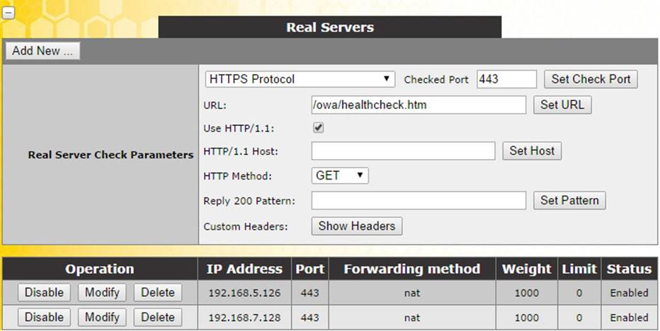
FIGURE 2-16 Setting OWA health checks on a Kemp load balancer
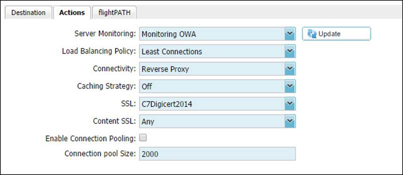
FIGURE 2-17 Setting OWA health checks on a JetNEXUS load balancer
Redundant load balancers The aim of both layer four and layer seven load balancers is to abstract from the client the state of the real server they are connecting to, and to ensure that loss of a server does not result in loss of a client’s ability to connect to the real server. But what happens when the load balancer fails, or as load balancers are typically available as virtual machines, what happens when the host machine fails and takes down the load balancer? Typically you would install two load balancers as a failover pair. One load balancer is active for the IP addresses that Exchange is being published across, and the other in the pair is passive. The two load balancers check the state of the other frequently, and the passive load balancer takes ownership of the virtual IP in the event of failure of the primary. Configuration within the load balancer says what happens when the passive comes back online. The virtual IP is represented at the network layer with a mac address that moves between the devices as required. As long as the switch in front of the load balancer can cope in a timely fashion to the switching of the mac address from one port to another, the client is not impacted during load balancing failover.
Geographically redundant load balancing When your datacenters are geographically separate you need to ensure that the load balancing devices are able to take ownership of the shared virtual IP in the event of an outage. In the case of geo-load balancing, if the primary load balancing pair go offline, as the datacenter is offline, the secondary load balancer sees this by way of a shared communication and updates the DNS record to point to their virtual IP. The load balancers are configured to provide DNS resolution for requests by the client. In a geo configuration, for say mail.contoso.com, either a new zone called “mail” is created within “contoso.com” and that zone is delegated to the load balancer cluster, or the record mail.contoso.com is a CNAME for a record in the zone hosted by the load balancer such as mail.geo.contoso.com, where geo.contoso.com is a zone that is delegated to the IP address of the load balancer (as shown in Figure 2-18). Then the IP address for mail.geo.contoso.com is the virtual IP from the working load balancer. When the working environment fails, the mail.geo.contoso.com record becomes the virtual IP of the load balancer in the second datacenter.
FIGURE 2-18 Configuring a delegation in Windows DNS to support geo-load balancing
Thought experiment: Patching Exchange Servers
In this thought experiment, apply what you’ve learned about this objective. You can find answers to these questions in the “Answers” section at the end of this chapter.
You are the network administrator of Contoso Pharmaceuticals and you have Exchange 2013 servers distributed across four sites. Each site has its own disaster recovery datacenter that office staff would relocate to in the event of their site becoming unavailable. Each database has four copies, two in the primary site and two in the DR site. The file share witness is located in a datacenter in a different region.
1. In the event of a single server failing, no databases become active in the DR site. But in the event of two servers failing at the same time, some databases become active in the DR site. What namespace do you need to have on your ExternalURL for servers in the DR site to ensure that users can connect to their database without issue?
2. In the event of a full site outage, planning has shown that Exchange can be brought online before users could reach the DR site to start work. Therefore, what namespace considerations do you need to make to ensure that users can connect to Exchange?
Objective summary
![]() The CAS role always routes a client to the mailbox server hosting the active copy of the database where their mailbox is located.
The CAS role always routes a client to the mailbox server hosting the active copy of the database where their mailbox is located.
![]() The CAS role proxies all connections to the correct mailbox server, using the same protocol as the client, after the client authenticates and the CAS role has queried the Active Directory to access the user’s mailbox information.
The CAS role proxies all connections to the correct mailbox server, using the same protocol as the client, after the client authenticates and the CAS role has queried the Active Directory to access the user’s mailbox information.
![]() Cross-site connectivity is much simpler in Exchange Server 2013 as the RPC protocol is not used outside of the active mailbox server. The RPC protocol typically requires low latency on the network and is susceptible to issues when high latency occurs. That was always a possible issue with Exchange 2010 when your CAS server was in one site and the mailbox had failed over to another.
Cross-site connectivity is much simpler in Exchange Server 2013 as the RPC protocol is not used outside of the active mailbox server. The RPC protocol typically requires low latency on the network and is susceptible to issues when high latency occurs. That was always a possible issue with Exchange 2010 when your CAS server was in one site and the mailbox had failed over to another.
![]() A single namespace is a possibility with Exchange Server 2013 due to this change in protocols used between servers.
A single namespace is a possibility with Exchange Server 2013 due to this change in protocols used between servers.
![]() Options for site resilience need to take into consideration the namespace used, that is, if it is bound to a given datacenter or unbound (where the same namespace is used everywhere).
Options for site resilience need to take into consideration the namespace used, that is, if it is bound to a given datacenter or unbound (where the same namespace is used everywhere).
![]() It is recommended to use the same certificate across all CAS role servers (or multirole servers, where you are setting the certificate on the CAS role specifically).
It is recommended to use the same certificate across all CAS role servers (or multirole servers, where you are setting the certificate on the CAS role specifically).
Objective review
Answer the following questions to test your knowledge of the information in this objective. You can find the answers to these questions and explanations of why each answer choice is correct or incorrect in the “Answers” section at the end of this chapter.
1. You need to request and install a digital certificate for the four client access servers that will be used in your Exchange Server 2013 deployment. (Choose all that apply.)
A. Run New-ExchangeCertificate on each CAS server
B. From the Exchange Admin Center generate a new certificate request for autodiscover.yourdomain.com
C. From the Exchange Admin Center generate a new certificate request for autodiscover.yourdomain.com and all of the names used by all of the CAS servers in all of the datacenters
D. Purchase a UCC digital certificate from a trusted third-party certificate authority
E. Delete the default certificate configured by the Exchange installation
2. You are creating a plan to ensure that if an Internet link failure occurs at your primary datacenter, and you successfully move your mailboxes over to the DR site, that all users will be able to connect. You want to do this with the least IT management tasks required. (Choose all that apply.)
A. Ensure that all ExternalURLs for all protocols are mail.contoso.com.
B. Ensure that OWA has its ExternalURL set to mail.contoso.com but that all other protocols have ExternalURL set to null.
C. Configure your internal DNS server to have an A record for each CAS server in both sites listed with their own IP address.
D. Configure your internal DNS server to have an A record for mail.contoso.com that has the IP address of your load balancer that load balances Exchange Servers in the primary datacenter as the IP address of this A record.
E. Configure your external DNS server to have an A record for each CAS server in both sites listed with their own IP address.
F. Configure your external DNS server to have the externally NATed IP address of your load balancer that load balances Exchange Servers in the primary datacenter.
Objective 2.3: Design, deploy, and manage site resilience for transport
So far in this chapter, you have considered site resiliency for mailbox databases with database availability groups, and client access servers by using consistent URLs and load balancers. The final service to consider is the transport services, or more specifically the SMTP protocol.
In Exchange 2010, the transport service was a role that you could co-exist with other roles or, though it was not recommended, install as a dedicated role. In Exchange 2013, as server hardware is at a point where installing the roles all on the same server is better, the transport role has disappeared as an installation option, but still exists on both the CAS role and the mailbox role. Because it is a role within Exchange Server 2013, we need to consider it for site-resiliency.
This objective covers how to:
![]() Configure MX records for failover scenarios
Configure MX records for failover scenarios
![]() Manage resubmission and reroute queues
Manage resubmission and reroute queues
![]() Plan and configure send/receive connectors for site resiliency
Plan and configure send/receive connectors for site resiliency
![]() Perform steps for transport rollover
Perform steps for transport rollover
Configuring MX records for failover scenarios
Email delivery in Exchange Server uses a number of different configuration options such as send connectors to deliver email away from a server or receive connectors to accept email onto a server. For both of these connectors, and for inbound and outbound connectors in Office 365 (which is covered in a later chapter), mail exchanger (or MX) resource records play an important part.
When an email is being sent from the Internet to Exchange Server (or any other email system), you either need a configuration known as a smarthost or MX records in public DNS. A smarthost value is the name or IP address of the server that you want to send the email to. This is controlling mail flow directly. To avoid managing how everyone on the Internet wants to send you email on an individual basis, if you publish in your public DNS zone an MX record that ultimately resolves to the IP address of your inbound email server, users on the Internet can email your users easily.
When you create an MX record in DNS you need to provide the following:
![]() You need to provide an A record in DNS that resolves to the external IP address of the system that receives email for your domain from the Internet. If you have a spam and virus filtering service in front of your Exchange Server, the IP address will be the external IP address of this device. If you have a cloud hosted spam and virus filtering service that you have subscribed to, you do not need to create the A record as the filtering company will have created it already, but you will need to know the name of this A record.
You need to provide an A record in DNS that resolves to the external IP address of the system that receives email for your domain from the Internet. If you have a spam and virus filtering service in front of your Exchange Server, the IP address will be the external IP address of this device. If you have a cloud hosted spam and virus filtering service that you have subscribed to, you do not need to create the A record as the filtering company will have created it already, but you will need to know the name of this A record.
![]() You need to provide an MX record created in your domain, typically with no host name, that uses the A record created above. If you have a spam and virus filtering cloud service in use, they will provide you with the A record.
You need to provide an MX record created in your domain, typically with no host name, that uses the A record created above. If you have a spam and virus filtering cloud service in use, they will provide you with the A record.
![]() You also need to provide a priority value. This is a number that you allocated to each MX record and which control the order that multiple records, if you have them, are used.
You also need to provide a priority value. This is a number that you allocated to each MX record and which control the order that multiple records, if you have them, are used.
In Figure 2-19 you can see the MX record creation dialog box from a Windows DNS server. This dialog box shows that the MX record for contoso.com has a priority of 10 and points to the Microsoft cloud hosted spam and virus filtering service called Exchange Online Protection (EOP). The value for the MX record in this case is provided by EOP to the Contoso administrators.
FIGURE 2-19 Adding an MX record in DNS
Different public DNS providers will have different ways for you to add MX records, but they will all require these three pieces of information. If you are hosting your own mail server or SMTP filtering service on premises it is important to note that the A record that the MX record refers to must be an A record (or AAAA for IPv6 records) and cannot be a CNAME record.
When a sending SMTP server wants to deliver to your domain, they look up the MX record in public DNS for your domain, resolve this to the IP address of the A record, and then connect to that IP address. This can be tested using the command line with Nslookup. The command line to type is nslookup -q=mx domain.com. Figure 2-20 shows you an example output.
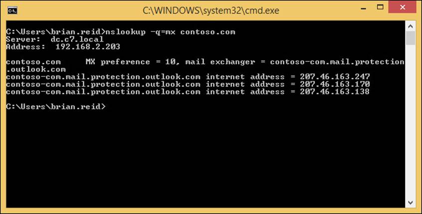
FIGURE 2-20 Nslookup output for an MX record query
You can see from this figure that there is an MX record of priority 10 and that resolves to three A records each with a different IP address. This is only one way to do high availability of SMTP services, because an SMTP server will automatically pick one A record from the list (usually the first one) and connect to that server. If that server does not respond, the next record on the list will be used. Within an Active Directory site, Exchange Servers use the same technique to connect to other servers. They resolve the IP addresses of all the Exchange mailbox servers in the site and then connect to one of them, and if that fails, connect to another. You do not need MX records within the Active Directory site, but the principle of connection is the same.
Behind each of the multiple IP addresses that this example MX record points to could be an SMTP server, or it could be a load balancer and a considerable number of servers. As SMTP manages its own load balancing you can publish a single IP per server on your external firewall direct to each inbound SMTP server that is able to receive from the Internet. If you are short of available IP addresses, you would use a load balancer. A load balancer can be used to remove connections from a server that is not responding, or to keep the number of connections across all of your servers about the same, but with SMTP it has its own retry functionality built into the protocol, so it is not always required.
In addition to having multiple A records behind a single MX record, you can have multiple MX records each pointing to a different SMTP host. If these records all have the same priority value, they will be used equally by the sending SMTP server. Imagine for example a domain with three MX records, all with priority 10, with the following hosts:
![]() mail-us.contoso.com A 131.107.2.200
mail-us.contoso.com A 131.107.2.200
![]() mail-gb.contoso.com A 131.107.6.150
mail-gb.contoso.com A 131.107.6.150
![]() mail-hk.contoso.com A 131.107.9.99
mail-hk.contoso.com A 131.107.9.99
When this domain is queried for its MX records using Nslookup, this would result in the answer shown in Figure 2-21.
FIGURE 2-21 Nslookup response to an MX query with more than one MX record
You can see from Figure 2-21 that each MX record is shown, and each A record IP address is shown. As DNS in this example is a DNS server that supports round robin, each A record and associated IP address will be returned in a different order each time. Therefore, each querying SMTP server would connect to the first returned IP address and send its email. Though as you can see from the example, this would mean that inbound emails would be distributed across the world irrespective of the sending server or the recipient because the first IP address returned to the sending SMTP server is done by DNS and is irrespective of the source or destination of the email.
Taking the above example, if the Hong Kong office was the primary office and the London and New York offices were to be used to receive email if the Hong Kong office went offline, you would either give mail-hk.contoso.com a higher priority than the other two records, or decrease the priority of the other two records. When talking of MX records, the lower the priority value, the higher the priority of the server. This means that an MX record with a priority of 10 will be connected to before any MX record with a priority of 20. The MX server with a priority of 20 will only be connected to when the 10 priority server does not respond. This can be seen in Figure 2-22. In this figure the Hong Kong office has a priority of 10 and the other two offices have decreasing priority (i.e. the numbers increase). Therefore, inbound email via MX record lookup will always go via mail-hk.contoso.com.
FIGURE 2-22 Nslookup showing different priority results for an MX record lookup
Note: MX Priority and Spam Filtering
It is a common theory that spam generating malware and the like, lookup the lowest priority MX record and deliver to that server on the premise that there might be less rigorous filtering, if any, on the server that is used for mail flow backup.
There is also a theory that a way to reduce your inbound spam is to publish an invalid server as your first MX record. Real SMTP servers will fail to connect and move onto the next lower priority server, but malware-generating spam will move onto another recipient.
Both of these theories are the opposite of each other and both will probably reduce inbound spam to some degree, but a good quality spam and virus filtering service is a must for any company.
Therefore, for inbound site resilient email delivery, you should have multiple MX records each of different priorities with the highest priority/lowest value being the A record to the primary server.
When you use a spam and virus-filtering service, there are different techniques to direct email to your preferred server after they have been sent through the filter, and to automatically use a secondary server in the event that the first becomes unavailable. The exact configuration will depend on the vendor of the server, but adding multiple smarthosts or IP addresses with a priority similar to that used in MX records is a common implementation.
Microsoft Exchange Online Protection uses a different technique for emails that clear the filter and are due to be delivered onward to an on-premises server. In Exchange Online Protection the outbound connector is used and the smarthosts value used to determine the IP address of the target server. If the smarthosts value is a name (and not an IP address), this name will first be looked up as an MX record, and then secondly resolved as an A record. This means that you can add a single smarthosts value that can be priority based. This is done by creating multiple MX records for inbound email that are different than the MX record for your domain (as that needs to point to Exchange Online Protection) either by creating an MX record for a hostname in your domain, or for a separate domain. In Figure 2-23 you can see the output from two Nslookup commands, the first for the domain and the second for onprem.contoso.com. The MX for contoso.com goes to EOP and the MX for onprem.contoso.com goes to mail-hk.contoso.com with a priority of 10, and if that is offline mail-gb.contoso.com as that record has a lower priority. In EOP the smarthosts value for the outbound connector would be onprem.contoso.com.
FIGURE 2-23 MX records for EOP and a site resilient EOP smarthost
In this example, EOP will deliver all filtered email to 131.107.9.99 (mail-hk.contoso.com) as the smarthost value in the connector reads onprem.contoso.com. If mail-hk goes offline, it will automatically use mail-gb.contoso.com, but while the mail-hk host is online it will never use the mail-gb host.
Managing resubmission and reroute queues
Within Exchange Server 2013, MX records are not used to deliver email between DAGs, sites, and servers. Instead a list of all the mailbox servers in the target DAG, or if not DAG, the target Active Directory site are used in a round robin fashion for connecting to. Each connection that a given transport server makes is logged into the connectivity log files. There is a connectivity log file for each transport service including FrontEndTransport on the CAS and Hub and Mailbox Transport on the mailbox role. An example of a connectivity log file can be found at C:\Program Files\Microsoft\Exchange Server\V15\TransportRoles\Logs\Hub\Connectivity for the transport service on the mailbox role. If a server is not responding and it is selected as a target for SMTP connections, this will be logged in the connectivity log as an attempt to connect. Because the connection will fail, the source server will pick another server, if there is another available, and connect to it. Therefore, for very simple and easy site and cross-site resiliency in Exchange Server, you should have more than one mailbox role (or multi-role) server per Active Directory site that you have Exchange Servers located in.
Exam Tip
It is always a good idea to have an understanding of least cost routing. Exchange Server only uses the least cost route to deliver messages, and so understanding the impact and where messages are likely to queue is a good candidate for an exam question. More information on least cost routing can be found at http://technet.microsoft.com/en-us/library/aa998825.aspx.
In the event that all the target servers in a DAG or site are offline, or the target network is unavailable, Exchange Server will attempt delivery to the nearest server to the point of failure. This is done by taking the Active Directory site link costs to the target site, or to the site that contains the nearest member of the target DAG, and connecting to the first available server along that least cost path. An example of this is shown in Figure 2-24. In this figure you can see five sites for a European company where the faster network, and therefore the Active Directory replication links, go through Paris. For fault tolerance, there are slower backup links direct to some regional offices, but with more costly Active Directory site links, they are not used unless the lower cost link is unavailable. The Zurich site is down so the Exchange Server in Zurich is unreachable. A user in London sends an email to a recipient whose mailbox is on the Zurich server. The least cost path for this email to take is London to Paris to Zurich, which would have a cost of 20. All other possible routes would have costs of 50 or higher and so Exchange Server will not use them because it only uses the least cost route. Remember that though the least cost route is calculated, Exchange Server will still attempt to connect directly to the target server in the destination site or DAG before any server on the route.
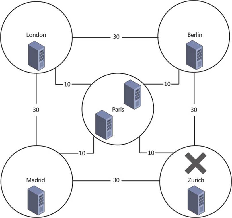
FIGURE 2-24 Least cost routing when a site is unavailable
Therefore, with Zurich being offline, the connection from London direct to Zurich will fail and so the Exchange Server in London will connect to one of the two Exchange Servers in Paris. If the Zurich site remains offline for a while, further emails from London to Zurich will begin to queue approximately evenly across both servers in Paris. Emails from Madrid and Berlin will also take the least cost route, which for them is the route via Paris. This means that emails from Berlin and Madrid senders will also queue in Paris. The direct links from Berlin and also from Madrid to Zurich are more expensive than the links via Paris, and so are not used.
On the Paris servers, the messages will queue and the queue will be retried every minute for five minutes, and then every 10 minutes until the messages time out at two days. Once the Zurich site is back online and the Exchange Server in Zurich is able to receive connections from Paris and the other sites, mail flow will resume within the retry time of 10 minutes.
Using Exchange Management Shell and the Retry-Queue cmdlet, a retry can be forced rather than waiting for the next retry interval. The next retry interval can be determined by using the Get-Queue cmdlet.
Considering Figure 2-24, imagine a scenario where the link from Paris to Zurich is unavailable, but the site is up and the separate links from Berlin and Madrid are online. In this scenario, email from London will still queue in Paris, but email from Madrid and Berlin will connect successfully. This is because although the least cost route from, for example, Madrid is Madrid to Paris to Zurich as a cost of 20, the Exchange Server in Madrid will make a direct connection to the server in Zurich and successfully connect.
The only way to get the emails queued on the Paris servers (from Paris and London senders) to Zurich while the link is down, would be to either change the cost of the Paris-Zurich link to more than 40 (so that the cost of the Paris to Berlin to Zurich link is less expensive), or to remove the Paris-Zurich link.
If you remove the link rather than increase the cost, note the following:
![]() The Paris, Madrid, Zurich link, which also has a cost of 40, will not be used because the Paris, Berlin, Zurich link will be chosen as the least cost route. This is because both Paris, Berlin, Zurich and Paris, Madrid, Zurich cost 40. Therefore, the hop count is used to choose the least cost route. In this example though, both routes have two hops and so a single least cost route has not been determined. When more than one route has the same least cost, and as there is still more than one route with the same hop count, the route that has the lowest alphabetical site name will be chosen. Therefore, in this example Paris, Berlin, Zurich will always be the least cost route over Paris, Madrid, Zurich given the above costs and hop count because Berlin is lower alphabetically than Madrid.
The Paris, Madrid, Zurich link, which also has a cost of 40, will not be used because the Paris, Berlin, Zurich link will be chosen as the least cost route. This is because both Paris, Berlin, Zurich and Paris, Madrid, Zurich cost 40. Therefore, the hop count is used to choose the least cost route. In this example though, both routes have two hops and so a single least cost route has not been determined. When more than one route has the same least cost, and as there is still more than one route with the same hop count, the route that has the lowest alphabetical site name will be chosen. Therefore, in this example Paris, Berlin, Zurich will always be the least cost route over Paris, Madrid, Zurich given the above costs and hop count because Berlin is lower alphabetically than Madrid.
![]() When any link cost or other factor that is used to determine least cost route is changed, only new messages are automatically evaluated for these changes. Existing messages already queued on a server have passed through the routing stage of the server and are waiting to connect to the determined next server. Their route will not automatically be recalculated.
When any link cost or other factor that is used to determine least cost route is changed, only new messages are automatically evaluated for these changes. Existing messages already queued on a server have passed through the routing stage of the server and are waiting to connect to the determined next server. Their route will not automatically be recalculated.
![]() The IP networking and routing is the same as the Active Directory site links. London does not have a direct site link to Zurich and so cannot connect to Zurich directly. There is no valid route from London, but there is a valid route to the other sites, and so Paris can be connected to.
The IP networking and routing is the same as the Active Directory site links. London does not have a direct site link to Zurich and so cannot connect to Zurich directly. There is no valid route from London, but there is a valid route to the other sites, and so Paris can be connected to.
To fix this issue without fixing the problem with the Paris-Zurich routers and link, the Paris-Zurich connector could be increased in cost from 10 to 100 (Set-ADSiteLink Paris-Zurich-ExchangeCost 100). If this was to happen, new emails from London would go London to Berlin to Zurich at a cost of 60, and emails from Paris would go Paris to Berlin to Zurich at a cost of 40. The London server would still attempt to connect directly to the Zurich server, but as it does not have connectivity, it would now connect to Berlin as that is the hop before Zurich on the least cost route, unlike Paris which was the previous hop when the link costs were lower. Once queued at Berlin, it would connect successfully to Zurich and bypass the broken connection between Paris and Zurich.
If London had IP connectivity direct to Zurich, there would be no need to change the costs as the messages would not queue in Paris.
In the above scenario where messages from London and Paris are queued on the Paris server and the cost of the Paris-Zurich link is changed to 100, you will also need to force the emails in the queue to be recalculated for routing so that they can be sent to Berlin. To do this, you would use the Retry-Queue –Resubmit $true cmdlet. For example, if you ran Get-Queue you might see 100 emails queued for the Zurich Active Directory site with a Queue ID of PARIS1\1234, where PARIS1 is the server name and 1234 is the queue ID. In this case, you would change the cost of the Paris-Zurich connector and then run Retry-Queue PARIS1\1234 –Resubmit $true. In the example shown in Figure 2-24, you would need to repeat this cmdlet, with the correct queue ID on PARIS2 as well (for example Retry-Queue PARIS2\554 -Resubmit $true where 554 is the queue ID on server PARIS2). This can be seen in Figure 2-25.
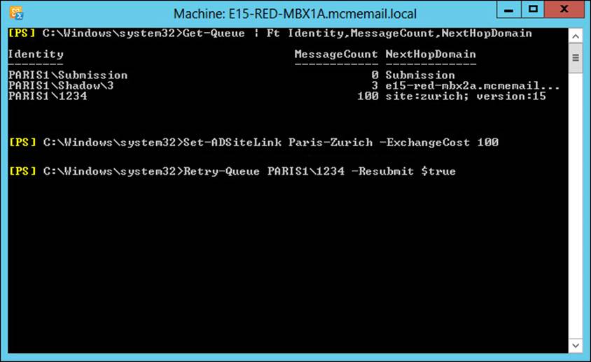
FIGURE 2-25 Resubmitting messages that are queued after site link costs changed
In the event that there are messages queued on a server, and you need to take that server down for maintenance, in Exchange Server 2013 there is the Redirect-Message cmdlet. This cmdlet will actively move messages from one Mailbox server (that is where the transport queue lives) to another server. To use Redirect-Message, you need to stop the server receiving inbound messages; otherwise, when the redirection is complete, it will be able to accept new messages again. Once the redirection is complete, you can run the required maintenance on the server knowing that the server will not be a valid target for incoming messages.
There are two cmdlets needed to take a server into maintenance from a transport perspective. These are:
![]() Set-ServerComponentState <SourceServerName> -Component HubTransport -State Draining -Requester Maintenance
Set-ServerComponentState <SourceServerName> -Component HubTransport -State Draining -Requester Maintenance
![]() Redirect-Message -Server <SourceServerName> -Target <TargetServerName>
Redirect-Message -Server <SourceServerName> -Target <TargetServerName>
Shadow and poison queues are never redirected to the other server. Therefore, for site resiliency, ensure that any server that is taken down for maintenance is back online as soon as possible. That server might contain shadow messages for other servers in the delivery group that, in the event of loss of those other servers or lagged copy rollback, this server might be needed for. Shadow messages are always stored on another server in the same delivery group as the receiving server. The delivery group is either other servers in the Active Directory site (if the server is not a member of a DAG), or other members of the DAG, or if the DAG has members on more than one site, the members of the DAG in the other site. For more details on shadow redundancy, see later in this chapter.
Planning and configuring send/receive connectors for site resiliency
As you have seen in the previous sections, you add additional MX records or IP addresses for the same host that the MX record uses to provide site resiliency for inbound email from the Internet. Within Exchange Server, you just need to have more than one mailbox role server to receive email from other Exchange Servers.
On the Exchange Server itself there are numerous receive connectors to accept the inbound email. The default receive connectors are as follows:
![]() Client Access Role:
Client Access Role:
![]() Default Frontend Servername
Default Frontend Servername
![]() Outbound Proxy Frontend Servername
Outbound Proxy Frontend Servername
![]() Client Frontend Servername
Client Frontend Servername
![]() Mailbox role:
Mailbox role:
![]() Default Servername
Default Servername
![]() Client Proxy Servername
Client Proxy Servername
Unlike Exchange 2010, there is no requirement to configure any settings to receive anonymous emails that are destined for your Exchange organization This requirement isn’t needed because the Default Frontend Servername receive connector accepts anonymous connections by default.
As each client access role server has a receive connector that accepts anonymous connections, configuring inbound mail flow for site failover scenarios comes down to load balancer or MX, server name or IP address configuration. For inbound email from the Internet, you need to have a way to ensure that when a site goes offline, that the standby site can take over emails easily. This is best done with two or more MX records of differing priority as discussed earlier, though geo-load balancers can be used as well for larger deployments.
For internal mail flow that starts outside the Exchange organization, for example application servers and devices that generate email notification and reports, these need to be configured with the IP address of an Exchange client access role server because these servers have the frontend transport service and anonymous submission should you need it. The problem with configuring applications and devices with an IP address is that you need to change it on all of the applications and devices when failover occurs, or when you upgrade to a newer version of Exchange, or add new servers. Therefore, the best way to control mail flow within the network inbound to Exchange is to use an MX record and an A record pointing to multiple IP addresses, and to use an FQDN that resolves to this MX or A record within the applications and devices.
This FQDN allows the IP to be changed in the event of a failure in the current target server, or to have multiple IP addresses and to make use of the native load balancing within the SMTP protocol. If you have applications or devices that can only take an IP address, or if you have multiple IP addresses in an A record and this negatively impacts these applications, you should use a load balancer to distribute the load and to allow simple failover to a different server or site in the event of an outage, or when it comes time to migrate to a new server.
Performing steps for transport rollover
In the event of an outage of either a CAS or mailbox role server, there may be impacts to message delivery that will need resolving, or impacts to messages that were in the queue on the server that failed.
In the event of server failure, any technology that directs connections to an alternative server will be sufficient. As discussed in previous sections of this book, this can include load balancers, or for inbound emails, more than one MX record or more than one IP for the MX or A record being used. In scenarios where you have one or more of these systems in place, new connections made after the time of failure will fail to connect to the box suffering outage, but will succeed in connecting to alternative servers.
If a message was currently in transit, a different scenario needs to be looked at first. All mail flow into Exchange Server 2013 should go via a client access server, and receive connectors on mailbox servers should not be modified to receive external traffic. When an email is received by the frontend transport service on a CAS role server, listening on TCP port 25, the initial connection is made and the SMTP headers accepted. Upon receiving the RCPT TO header, the frontend transport service queries the Active Directory to determine the mailbox database of these recipients. If these recipients are mailboxes, the frontend transport service makes a connection to the DAG or site (if the mailbox is not in a DAG) that contains the active mailbox copy. If there is more than one recipient, an evaluation of up to the first 20 recipients is made to determine which DAG or site should be used for the majority of these first 20 recipients. If the recipients are distribution lists or other mail objects (mail users, and so on), a connection is made to a mailbox role server in the same site as the CAS server.
Once this connection is made, the body of the message is passed through the CAS frontend transport service without further modification or inspection. It is passed to the selected mailbox role server and the transport service on that server.
Upon being received by this transport service on the mailbox role server, and before the sending server in front of the CAS role has received any acknowledgement of receipt, the transport service connects to another transport service in the same delivery group. That is, if this is a cross-site DAG member, it will attempt to connect to a member of the same DAG in a remote site. If the DAG is not cross-site, or there is no response from up to four remote DAG members, it will connect to a DAG member in the same DAG and same site. If the mailbox server is not a DAG member, it will attempt to connect to up to two servers in the local Active Directory site. These values for cross-site and local site retries can be configured via Set-TransportConfig and can be seen in Figure 2-26.
FIGURE 2-26 Get-TransportConfig showing shadow redundancy related settings
Once connected to a second transport service on another mailbox server in the same delivery group, a copy of the message, the shadow message, will be sent to this server to be kept for two days (or the ShadowMessageAutoDiscardInterval from Get-TransportConfig if this has been changed). The second transport server acknowledges the first for successful receipt of the shadow message. The first transport server acknowledges the frontend transport proxy service of successful receipt of the message and then, and only then (unless connections time out), does the frontend transport service acknowledge the sending SMTP server.
This sequence of events means that should a server fail during receipt of a message or receipt of the shadow, the preceding server will reconnect automatically to redeliver.
Once the transport service has the message in its queue, it will connect to the mailbox transport service on the server containing the active copy of the mailbox. The message is handed to the mailbox transport service over SMTP to port TCP 475 on the actual server holding the active mailbox. If this server should fail during delivery, the holding transport server can redeliver. If the holding transport server should fail while queuing this message, the shadow holder will promote its copy of the message to the primary copy and deliver it should it not receive acknowledgement of successful delivery from the primary transport service after three hours. Three hours is the ShadowHeartbeatTimeoutInterval x ShadowHeartbeatRetryCount, or 12 x 15 minutes = 3 hours.
Both the transport service holding the primary copy of the message, and the shadow copy of the message persist the message in the mail queue database for two days. This persistence of the mail queue database is known as the Safety Net. In the event of delivery failing to the database, or the database failing over to a passive copy of the database and suffering loss of log files, and therefore loss of messages, the copy of the message in the transport mail queue database (the Safety Net) can be redelivered automatically.
In the event of a lagged database copy being mounted without being replayed, for example in the case of logical database corruption such as an active deletion of data or virus outbreak, the mail queue database can replay up to its stored duration and so result in minimal data loss even though the database has been rolled back in time. Therefore, it is important that the duration of time that the mail queue database stores messages, which is two days by default, equals or exceeds the ReplayLagTime value on a mailbox database copy. The SafetyNetHoldTime parameter on Set-TransportConfig defaults to two days and can be increased as the ReplayLagTime can be up to 14 days.
 Thought experiment: Configuring send connectors
In this thought experiment, apply what you’ve learned about this objective. You can find answers to these questions in the “Answers” section at the end of this chapter.
You are the network administrator of Northwind Traders Inc. and you have a CRM and sales application that sends invoices and receipts by email following an online purchase.
1. How would you configure any connectors in Exchange to ensure all invoices and receipts are journaled before onward delivery, and that a single server outage does not stop the delivery of these invoices and receipts?
2. What permissions would you need to set on the connector to allow relay of messages to the Internet? (There are three possible answers here.)
Objective summary
![]() Use a single MX record and multiple A records if you have a single site and multiple servers. If you have more than a handful of servers, a load balancer is usually a better option and a single IP address on the MX record.
Use a single MX record and multiple A records if you have a single site and multiple servers. If you have more than a handful of servers, a load balancer is usually a better option and a single IP address on the MX record.
![]() For smarthost values use a FQDN rather than an IP address because it is easier to manage change in the longer term.
For smarthost values use a FQDN rather than an IP address because it is easier to manage change in the longer term.
![]() For multiple sites with inbound SMTP connectivity, either use a cloud hosted filtering service that can direct users’s email to the correct site, for example using conditional routing in EOP. If there is no facility in the cloud filtering service, or a cloud filtering service is not an option, use the highest priority MX record for the primary site.
For multiple sites with inbound SMTP connectivity, either use a cloud hosted filtering service that can direct users’s email to the correct site, for example using conditional routing in EOP. If there is no facility in the cloud filtering service, or a cloud filtering service is not an option, use the highest priority MX record for the primary site.
![]() For message resubmission, remember least cost routing. Understanding this will help you determine the servers that will queue messages given specific site, network, and server failures.
For message resubmission, remember least cost routing. Understanding this will help you determine the servers that will queue messages given specific site, network, and server failures.
![]() Use the -Resubmit parameter of Retry-Queue in the event that you want queuing emails to be reevaluated for new routes if changes have been made that will change the least cost route to a target site or DAG.
Use the -Resubmit parameter of Retry-Queue in the event that you want queuing emails to be reevaluated for new routes if changes have been made that will change the least cost route to a target site or DAG.
![]() Take a look at http://vanhybrid.com/2013/11/28/script-putting-exchange-server-2013-into-maintenance-mode/ for a script that will help you place a server into maintenance mode.
Take a look at http://vanhybrid.com/2013/11/28/script-putting-exchange-server-2013-into-maintenance-mode/ for a script that will help you place a server into maintenance mode.
![]() Exchange Server 2013 should have no requirement to modify receive connectors for anonymous submission. For authenticated client submission, the recommendation is to use port 587 and not 25. Authentication on port 587 will allow relay if the authentication is successful.
Exchange Server 2013 should have no requirement to modify receive connectors for anonymous submission. For authenticated client submission, the recommendation is to use port 587 and not 25. Authentication on port 587 will allow relay if the authentication is successful.
![]() Set-TransportConfig is used to configure the shadow redundancy timeouts and settings such as whether to use a cross-site DAG or only to use the same site (regardless of DAG node location).
Set-TransportConfig is used to configure the shadow redundancy timeouts and settings such as whether to use a cross-site DAG or only to use the same site (regardless of DAG node location).
![]() Ensure that any lagged database has a ReplayLagTime of less than or equal to the SafetyNetHoldTime.
Ensure that any lagged database has a ReplayLagTime of less than or equal to the SafetyNetHoldTime.
Objective review
Answer the following questions to test your knowledge of the information in this objective. You can find the answers to these questions and explanations of why each answer choice is correct or incorrect in the “Answers” section at the end of this chapter.
1. Contoso wants to have a 7 day lagged database copy and wants to ensure that their SafetyNet duration is set to the same value. What command would they use?
A. Get-TransportService | Set-TransportService -SafetyNetHoldTime 7Days
B. Get-TransportService | Set-TransportService -SafetyNetHoldTime 7:00.00
C. Set-TransportConfig -SafetyNetHoldTime 7Days
D. Set-TransportConfig -SafetyNetHoldTime 7:00:00
2. Which of the following accepted domains can be included in an email address policy?
A. Authoritative
B. InternalRelay
C. OpenRelay
D. External Relay
3. Contoso and Fabrikam are two divisions of the same company. Both were historically separate entities and remain so for email due to compliance reasons. Both organizations have an Exchange Server 2013 deployment in two different datacenters and they use rack space at the partner company’s datacenter to host passive DAG nodes. They would also like to use the Internet connection of the partner in the event of an outage with their own connection for inbound mail flow. What do they need to configure in addition to the records pointing to the primary datacenter?
A. Create the following DNS records:
contoso.com MX 5 mail.fabrikam.com
fabrikam.com MX 5 mail.contoso.com
B. Create the following DNS records:
contoso.com MX 10 mail.fabrikam.com
fabrikam.com MX 10 mail.contoso.com
C. Create the following DNS records:
contoso.com MX 20 mail.fabrikam.com
fabrikam.com MX 20 mail.contoso.com
D. For each organization, create an internal relay accepted domain and a send connector with the matching address space as the accepted domain.
E. For each organization, create an external relay accepted domain and a send connector with the matching address space as the accepted domain.
Objective 2.4: Troubleshoot site-resiliency issues
This objective of the site resiliency chapter looks at different troubleshooting options to consider for diagnosing and finding faults within the items that we have looked at throughout this chapter.
This objective covers how to:
![]() Resolve quorum issues
Resolve quorum issues
![]() Troubleshoot proxy and redirection issues
Troubleshoot proxy and redirection issues
![]() Troubleshoot client connectivity
Troubleshoot client connectivity
![]() Troubleshoot mail flow
Troubleshoot mail flow
![]() Troubleshoot datacenter activation
Troubleshoot datacenter activation
![]() Troubleshoot DAG replication
Troubleshoot DAG replication
Resolving quorum issues
For your database availability group to be online and able to mount databases it must have quorum. That is to say it must have a majority of servers in the cluster online. If it does have exactly the minimum number of servers required to reach majority, then the file share witness will have a file locked on it to add an additional vote and maintain quorum. This ensures that should the DAG drop to an equal number of nodes online and offline (or unreachable), the DAG will stay online in the primary site. With the file share witness it means you will always have one datacenter in a multi-site DAG that should be able to reach quorum and the other site would fail to reach quorum. Datacenter Activation Coordination (DAC) mode is an additional check within a DAG to ensure that not only does a majority need to be present but nodes must contact another node with their DACP bit set to 1 before being able to mount their databases. DAC mode is disabled by default but should be enabled on all DAGs with two or more servers.
When you have an outage that takes away a single DAG node, you are taken closer to not having quorum. When quorum is lost, all the databases in the cluster dismount. Therefore, it is important to understand quorum and ensure that network outages and maintenance events would not place you in a position of losing quorum. In Windows Server 2008 R2, quorum is calculated as a majority of the total number of nodes in the cluster and unless you evict nodes from the cluster (as you do in a failover event with Restore-DatabaseAvailabilityGroup) your majority is always calculated from the total number of nodes in the cluster that are online or offline. In Windows Server 2012 R2, as individual servers go offline, the total node count for majority is recalculated and therefore majority can remain with fewer nodes online. Note that this feature, called dynamic quorum, is enabled by default in 2012 R2 but is available in Windows Server 2012.
Troubleshooting quorum is therefore a knowledge of the operating system in use under Exchange Server, the total or online number of nodes and what half + 1 of this count is because half + 1 is the majority.
To find out your cluster configuration in the DAG you can use PowerShell commands such as Get-Cluster, Get-ClusterNode, and Get-ClusterQuorum. Some of these are shown in Figure 2-27.
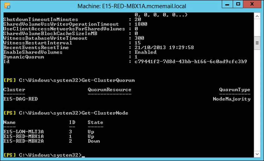
FIGURE 2-27 Cluster reports via Windows PowerShell
Troubleshooting proxy and redirection issues
All client connectivity to an Exchange 2013 mailbox happens through the Client Access Server role. The CAS role is an intelligent proxy server for Exchange Server clients. It authenticates the client or determines the recipient of the mail message and forwards the network traffic to the server that is active for that mailbox (the server that’s hosting the active/mounted copy of the database with the user’s mailbox in it). Therefore, if client connectivity to a 2013 mailbox is failing there are two places to consider. The first is the CAS role and the second is the mailbox server that is active for that user’s mailbox. If you have multiple CAS role servers, the first step to troubleshoot is to use a different server. If you have a load balancer make sure that it is configured to detect individual protocol health issues and redirect clients when Exchange managed availability updates the Healthcheck.htm file for each protocol.
If the CAS servers are working okay and are able to proxy the connection to a mailbox server, but there is still no connectivity, you would troubleshoot issues with opening the actual mailbox. Also consider using various protocols to see if it was protocol specific. Exchange Server can quarantine mailboxes that introduce performance issues to the server and a mailbox in quarantine would be unavailable, whereas other mailboxes on the same database would be working fine.
More Info: Mailbox Quarantine
More details on mailbox quarantine can be found at http://technet.microsoft.com/en-us/library/jj218650(v=exchg.150).aspx.
When the mailbox is located on a legacy Exchange Server and the client connects to a CAS 2013 server, the CAS 2013 server will prefer to proxy the connection to the target Exchange version unless the connection is to OWA on an Exchange 2007 server, or to OWA or ECP on an Exchange 2010 server with the External URL set. In these two cases the CAS 2013 server will redirect to the legacy URL for OWA 2007, and the External URL for OWA/ECP 2010. Exchange 2013, apart from the two cases above, will proxy to the FQDN of the 2007 or 2010 Exchange Server. Therefore, for legacy Exchange connectivity each Exchange Server needs to be able to connect directly to the FQDN of each legacy server in the organization. It is worth pointing out that firewalls between Exchange Servers and other Exchange Servers and domain controllers are not supported.
More Info: Proxy and Redirection
Much more detail on proxy and redirection can be found in the Exchange Team blog at http://blogs.technet.com/b/exchange/archive/2014/03/12/client-connectivity-in-an-exchange-2013-coexistence-environment.aspx.
Troubleshooting client connectivity
When you have client connectivity issues, the first piece of troubleshooting is to see the scope of the issue. Does it affect everyone, or one person, or somewhere in between? Once you have a scope to the issue you can look for something that might be common between all of the users. For example, are they all in the same database or site or something that would allow you to tie the connection issue to something you can go and investigate?
For client connectivity, another great tool is the ability to use multiple client types to connect to Exchange Server. For example, if Outlook is having an issue, do you get the same with OWA? If SMTP is having an issue, what about IMAP or POP3, if you are using a client that uses these protocols? If you can limit connectivity issues to a given client type, that will help. For issues where clients cannot connect, but you are able to open a web browser and login to OWA, start troubleshooting at any recent changes and consider settings and configuration such as AutoDiscover as part of client troubleshooting because OWA does not need AutoDiscover (unless you are using OWA for Devices on the iPhone/iPad or Android phone because AutoDiscover is used by these apps).
Once you have a scope of the issue, and a client that the problem is exhibited in, you are a good way to looking for an answer. Always examine the event viewer logs on a server to see if an issue is caused by something that might be surfaced in the logs, and always be very careful about making changes to fix issues without a good understanding of the issue first, as a change could compound the problem.
Troubleshooting mail flow
To understand and troubleshoot mail flow is to understand the SMTP protocol, which Exchange Server services do what, and what the connectors and other configuration items are used for.
Troubleshooting connectors
Receive connectors in Exchange Server are the SMTP server. To send email into and across an Exchange Server organization, email is accepted by a receive connector. When there is more than one receive connector on a target machine, the connectors need to be configured so that they either listen on a unique IP address or port (the connectors binding) or that they answer for specific ranges of IP addresses. Troubleshooting for specific bindings is easy. As long as you can make a connection to the binding IP and port, you know connectivity is working. But how can you tell if you have connected to the right receive connector when the connector is supposed to answer you based on your source IP address? The easiest way to do this is to configure the banner property of the receive connector. The banner is the message that starts with 220 that you receive when you connect to a receive connector. If you set each receive connector on a server to a unique value, you can clearly tell which receive connector you have reached when you connect to it on its listening IP address and port.
Once you have made a successful connection to the listening IP address and port, it is also useful to be able to enter the commonly expected SMTP verbs by way of a telnet session. To open a session using the telnet client to a remote Exchange Server, use telnet remote_IP_address port. If you were trying to connect to server 131.107.2.200, you would type telnet 131.107.2.200 25 and you would expect to see 220 and the configured banner, or if it’s the default banner, you would expect to see 220 and the server name and date/time. Once you have connected, use the EHLO domain.com command to say hello to the remote server and to tell it your domain name. It should respond with 250 OK or 250-SomeSMTPVerbs and then 250 VERB. The last line will read 250 space verb. All of the other lines will read 250 hyphen verb.
After the supported verbs are returned, try MAIL FROM: email.address@domain.com and then RCPT TO: valid.address@recipient.domain.com. When telnetting into Exchange Server on port 25, you cannot enter an external email address unless you are connecting to a receive connector that allows for relay.
The DATA command follows the successful entry of the MAIL FROM and RCPT TO commands. You can have one MAIL FROM and one or more RCPT TO commands. One DATA command ends the message envelope and moves onto the message body.
In the message body, enter To:, From:, and Subject: all with valid values after the colon and each on their own line. After Subject: have a blank line to end the headers, and then type the message body. Finish the message with a period on a line on its own followed by QUIT.
If in any of the verbs typed previously, you do not get the expected response, (for example the response shown in Figure 2-28), you have further troubleshooting to do. The most common reason why an anonymous connection will fail to an Exchange Server is if the server is out of resources such as disk space or memory and is known to be in a state called backpressure. A look in the event logs will give the reason. When this is resolved, mail flow will automatically resume.
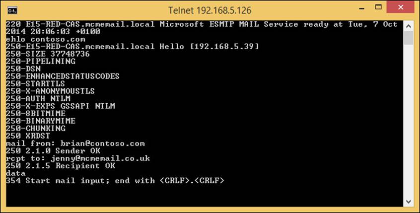
FIGURE 2-28 Using telnet client to successfully connect to an Exchange Server receive connector
More Info: Event Logs and Backpressure
The website at http://technet.microsoft.com/en-us/library/bb201658(v=exchg.150).aspx covers more details on the entries found in the event log during backpressure.
Outbound connectors, or send connectors on the transport service, will queue messages that cannot be delivered. All of the other send connectors on other services are stateless and do not queue messages. Therefore, if there is a problem with a send connector that uses a Frontend CAS to proxy through, it will queue in the transport service. If the destination is offline or otherwise unavailable, the message will queue in the transport server that holds the send connector to that destination. If the transport service is offline, the mailbox transport submission service, which delivers messages between the mailbox and the transport service, will not queue and the message will stay in the outbox in the client.
Exam Tip
Different clients will use different folders to send email from. They will not always use the Outbox. Messages that are being sent from OWA will stay in Drafts until they are sent and messages in Outlook cached mode will use Sent Items to send the email from (unless you are disconnected). Outlook in online mode uses the Outbox as its delivery folder.
When messages are queued on the transport service you can use Get-Queue or Get-QueueDigest to review the queue on a given machine, or across all of the machines in the DAG or site. Get-Queue | Format-List LastError will return the last error on any given queue. Sometimes you will not get an error on a queue, but will get errors on the messages in the queue, and for this you need to use Get-Message | Format-List LastError instead.
Troubleshooting transport services
In Exchange Server 2013, there are a number of transport services. These are as follows (with the process name in brackets) and the role the service runs on listed as well:
![]() Mailbox server role
Mailbox server role
![]() Transport (EdgeTransport.exe)
Transport (EdgeTransport.exe)
![]() Mailbox transport delivery service (MSExchangeDelivery.exe)
Mailbox transport delivery service (MSExchangeDelivery.exe)
![]() Mailbox transport submission service (MSExchangeSubmission.exe)
Mailbox transport submission service (MSExchangeSubmission.exe)
![]() Client Access Server role
Client Access Server role
![]() Frontend transport (MSExchangeFrontendTransport.exe)
Frontend transport (MSExchangeFrontendTransport.exe)
The frontend transport and the two mailbox transport services are stateless, that is they proxy messages and do not store them on disk. Frontend transport finds the correct mailbox server to proxy the message to, that is it will deliver the message to any server in the same DAG or site (if not a DAG member) as the active mailbox and to any local mailbox server in the same site for messages going to legacy servers or distribution groups.
If frontend transport is not running, TCP port 25 will not be listening on the CAS server. The transport service on the mailbox server will listen on TCP 25 if it is a mailbox only role server, but on TCP 2525 if it is co-located with a CAS role server, so that CAS only listens on TCP 25. You cannot have two services listening on the same port, though in Exchange 2013 it is possible to build receive connectors on the transport service that listen on port 25 when CAS is also listening on that port. This can cause lots of issues, so ensure on all co-located servers that you always bind receive connectors to frontend transport service.
The mailbox transport services send messages to databases (mailbox delivery) and receive from the mailbox databases (mailbox submission). If either of these services are offline then sending or receiving from the database will not occur.
Note: Health Manager
Exchange 2013 comes with the Health Manager service. The job of the Health Manager is to check the health of Exchange, such as can it log into OWA, or send and receive emails, and so on, and if not, to fix the issue. Often this will involve restarting services and can involve blue screening the server to force a reboot (in the event that the disks are not responding). Therefore, it can be the case that the issue is gone by the time you get a report about it, because the Health Manager will have started or restarted the service for you.
Therefore, look up maintenance mode for Exchange Server because that is how you tell the Health Manager not to restart stuff or attempt to fix stuff if you have the server offline or partially offline on purpose.
Troubleshooting transport-related configuration
Change is usually the biggest cause of outages in IT systems. For example, someone has changed something and now something is broken. For transport, the objects that you need to configure to ensure valid mail flow typically work until something changes in them or the send to or receive from targets change, such as a smarthost of firewall rule changes and now the smarthost is unreachable.
Always have change control and keep a record of all configurations before they are changed and after they are changed. In Exchange Management Shell (and Windows PowerShell in general), this is easy to implement with the use of Start-Transcript and then at the end Stop-Transcript. This records everything you do to a log file. Therefore before you make changes, for example to an Accepted Domain, you would run Get-AcceptedDomain | fl to write to the screen and also to the transcript log file, the configuration you have in place at this time. Then make your changes. If you need to role these changes back, you have what you need to role it back to.
If you use ECP to make changes, remember that the admin audit log can be queried to show you what you have changed, but it will not show you what it was before the change was made!
Troubleshoot datacenter activation
If you have a site failover and you need to activate passive copy databases in your secondary datacenter, you need to ensure that you use the Stop-DatabaseAvailabilityGroup and the Restore-DatabaseAvailabilityGroup cmdlets. This adds the servers that are part of the cluster in the failed site (Stop-DatabaseAvailabilityGroup-ActiveDirectorySite PrimarySiteName) to the DAG stopped servers list, and then the Restore cmdlet evicts them from the cluster and reduces the node count so that majority can be obtained in the secondary/surviving datacenter.
Unless you have the file share witness in a third site that the secondary datacenter can access and the primary cannot, you must do manual processes like the one described here to perform a failover to the other site. With a file share witness in the third site that both sites have independent access to, you can have automatic failover as long as both sites hold an even number of cluster nodes and at the point of failure, the primary site goes down, but the third site with the file share witness does not then automatic failover occurs as majority is maintained.
If you do not have DAC mode enabled, which you should on a two or mode node DAG, then you need to use cluster commands to assist in the failover process. With DAC mode, as well as stopping split-brain scenarios, this allows you to use Exchange cmdlets only to manage the DAG instead of needing to know the additional cluster commands as well.
Troubleshooting DAG replication
Unless it is otherwise changed, DAG replication occurs over port 64327.Therefore, this port should be open for connectivity between nodes of the same DAG, though of course it is not supported to have any firewall between any Exchange Server and it can generate unexpected results.
For the Database Availability Group, replication happens on the replication network if one has been designated. Ports need to be open for this connectivity on the network that Exchange expects it to be on.
To see the state of the replication of your DAG, use Get-DatabaseAvailabilityGroup to find the DAG settings. Use Get-MailboxDatabaseCopyStatus to find the state of the replication and which servers are active for which databases, such as. which server the database is mounted on. The copy and replay queue lengths, described below, should ideally be low (<10) unless you are looking at a lagged database, which will have a high replay queue but should still have a low copy queue.
The Get-MailboxDatabaseCopyStatus cmdlet will return the database status of the local machine and show the health of the database. One server in the DAG should have the database Mounted, and other servers should have the database Healthy. Disconnected and other states should be investigated. From Figure 2-29, you can see Get-MailboxDatabaseCopyStatus run against the local server (with no additional parameters) and against a remote server (Get-MailboxDatabaseCopyStatus -Server servername).
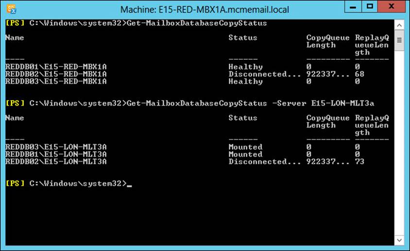
FIGURE 2-29 Get-MailboxDatabaseCopyStatus against two servers in the same DAG
Figure 2-29 shows that the databases that are working are mounted on the second server in the output and healthy on the first with no copy queue or replay queue. One database is offline and has an unreachable source database, hence the large number of items to copy, - which is actually showing an error rather than real count of logs outstanding.
Using Get-MailboxDatabaseCopyStatus, you can find out the count of transaction logs that are created on the server that holds the mounted, or active, copy of the database and that need to be shipped to all the other copies of the database. They are copied from the active copy to each passive copy. There is no passive-to-passive copying. It is important to note that if you have multiple passive copies of a database on the far side of a WAN link, the logs will be copied once per passive copy and will require double or more bandwidth.
Use Get-MailboxDatabaseCopyStatus on each passive copy to see the log copy status. If a server is behind on its log copy, it will have a higher than expected value. You should troubleshoot the log replication process from the active to that passive server.
Once logs arrive on the passive server, they are inspected for integrity and copied again if they fail the inspection. They are then written into the passive database replica. If there are issues writing the log into the database, for example on a disk with poor write speeds, the replay log count will increase. On a lagged database copy, there will always be a replay queue length of the number of transaction logs generated in the time window that the database is lagged by. On a server with a generally consistent level of activity and mail flow, this number will generally be the same from one day to the next at the same time of day. It will fluctuate over the day and week because the active copy will change in terms of its activity levels. For a lagged database copy, consider the values of the replay queue length that you expect and ensure that these are not massively over your expectations.
If you have a large copy queue length or a large replay queue length on a passive server, you will need the disk space to store these logs. For a large copy queue length, it will mean the logs are not removed from the active copy even if the active copy is backed up. Always attempt to fix the copy or replay issue rather than manually deleting log files. If you delete a log file that is required by a passive copy of that database, you will most likely have to reseed the entire database.
Thought experiment: Planning namespaces
In this thought experiment, apply what you’ve learned about this objective. You can find answers to these questions in the “Answers” section at the end of this chapter.
You are the network administrator of Alpine Ski School. An avalanche has hit your office and it is now destroyed. You want to recover Exchange Server in your DR site down the mountain. The top-of-the-mountain Active Directory site is called MountainTop and the DR site is called Basecamp. What do you need to do?
Objective summary
![]() A DAG needs to maintain quorum for databases to remain mounted in it. You looked at ensuring that maintenance, patching, etc. do not cause an entire DAG outage due to less than the majority of the DAG nodes remaining online.
A DAG needs to maintain quorum for databases to remain mounted in it. You looked at ensuring that maintenance, patching, etc. do not cause an entire DAG outage due to less than the majority of the DAG nodes remaining online.
![]() Unexpected failures can happen. Do not actively shutdown servers for maintenance that will bring you close to losing majority.
Unexpected failures can happen. Do not actively shutdown servers for maintenance that will bring you close to losing majority.
![]() If you evict servers from a cluster and therefore from the DAG, you will need to copy the entire database back to that server when you add it back into the DAG unless all of the log files containing all of the changes are still available on the active node. Do not remove servers from clusters unless there is a site failover or the end of the server’s role within the DAG.
If you evict servers from a cluster and therefore from the DAG, you will need to copy the entire database back to that server when you add it back into the DAG unless all of the log files containing all of the changes are still available on the active node. Do not remove servers from clusters unless there is a site failover or the end of the server’s role within the DAG.
![]() For the most part, Exchange will proxy connections through the CAS role to the active mailbox server or to a legacy server in the same Active Directory site as the mailbox. There are only a few occasions where a redirection occurs and these are for OWA 2007, where the user is redirected to the legacy namespace (which is required), and OWA 2010 where the user is redirected to the ExternalURL if one is set.
For the most part, Exchange will proxy connections through the CAS role to the active mailbox server or to a legacy server in the same Active Directory site as the mailbox. There are only a few occasions where a redirection occurs and these are for OWA 2007, where the user is redirected to the legacy namespace (which is required), and OWA 2010 where the user is redirected to the ExternalURL if one is set.
![]() In the case of redirecting from Exchange 2013 to Exchange 2010 with an ExternalURL set, you will need to authenticate again if you are running a lower cumulative update release.
In the case of redirecting from Exchange 2013 to Exchange 2010 with an ExternalURL set, you will need to authenticate again if you are running a lower cumulative update release.
![]() Use the Health Manager service and Managed Availability to try to ensure that Exchange Server remains functional and healthy, and to failover databases and restart services/servers to try and resolve issues.
Use the Health Manager service and Managed Availability to try to ensure that Exchange Server remains functional and healthy, and to failover databases and restart services/servers to try and resolve issues.
![]() Use the Get-MailboxDatabaseCopyStatus cmdlet to know the copy status of your databases and to help ensure your databases remain with their replicas up to date.
Use the Get-MailboxDatabaseCopyStatus cmdlet to know the copy status of your databases and to help ensure your databases remain with their replicas up to date.
Objective review
Answer the following questions to test your knowledge of the information in this objective. You can find the answers to these questions and explanations of why each answer choice is correct or Incorrect in the “Answers” section at the end of this chapter.
1. Which of the following Windows PowerShell commands will return the list of servers and the state of the servers in a cluster?
A. Get-ClusterNode
B. Get-ClusterServer
C. Get-Cluster <Name> | FL *node*
D. Cluster.exe Node
2. You notice that when using Get-MailboxDatabaseCopyStatus on a server that hosts only passive database copies, you have a large copy queue length of over 10,000 logs for one of these databases. Which of the following could be the potential impacts of this issue?
A. Backups will not truncate log files.
B. Disk space for logs might run out.
C. The active database might dismount.
D. The transaction logs on the lagged copy will auto play forward.
3. What does the RCPT SMTP verb do?
A. It tells the SMTP server to send a read receipt.
B. It tells the SMTP client to send a read receipt.
C. It tells the SMTP client that the email has been received.
D. It tells the SMTP server the email address of the recipients of the email.
Answers
This section contains the solutions to the thought experiments and answers to the objective review questions in this chapter.
Objective 2.1: Thought experiment
1. You can switch off three servers in the primary site or one server in the primary site and both servers in the secondary site.
2. To prevent outage in the event of a non-resilient WAN failure during server maintenance, a single node can be successfully taken offline at a time. If any server in the secondary site in unavailable, you are limited to a single server in the primary site. Different combinations of answers are available based on the number of servers that are online at any given time, and the Mailbox Role Calculator is a great tool for helping you understand these numbers for a given scenario.
Objective 2.1: Review
1. Correct answer: C
A. Incorrect: Resume-DatabaseAvailabilityGroup is not a valid cmdlet.
B. Incorrect: Start-DatabaseAvailabilityGroup is used to restart the DAG in the failed site that is back online again. It is not used to reduce the DAG to just the secondary site and bring the DAG online in the event of a failure.
C. Correct: The correct commands are Stop-DatabaseAvailabilityGroup followed by Restore-DatabaseAvailabilityGroup.
D. Incorrect: The question says the alternative witness server has already been set so it is not needed to be set again, but if it was needed it would be set as a property of the DAG with Set-DatabaseAvailabilityGroup –AlternateWitnessServer.
2. Correct answer: C
A. Incorrect: This answer does not meet the requirement for a failure scenario because all of the databases would go online in Madrid in the event of a site outage.
B. Incorrect: This answer would result in an outage of servers or sites failing to Tokyo or San Francisco. If the failure was a network failure that isolated Madrid mailboxes, these users would come online in the other data centers and not where the users are located.
C. Correct: Each user population needs a DAG that in the event of failure comes online in their nearest datacenter. If a failure occurred in any of the other answers there would be a scenario where some users’ mailboxes would come online in a site that the user could not access.
D. Incorrect: This is not a valid DAG design. All servers that hold a replica of a database must be in the same DAG.
Objective 2.2: Thought experiment
1. As each site with its associated DR site is geographically separate you can use the bound namespace model and bind a namespace to each region. For example, the UK region would be mail-uk.contoso.com and the US region mail-us.contoso.com. The unbound model would work (mail.contoso.com for everyone) though this would depend upon factors not described in the question. As Exchange 2013 does not have an RCP connection between servers you can connect to a CAS proxy in the primary site and successfully reach a server in the remote site. The ExternalURL in the DR site should be the same in the primary site.
2. Because you have the files share witness in a third site, you can bring Exchange online in the DR site automatically. You only need to make sure that the DNS A record for the namespace points to the load balancer in the DR site. If you have a geo-load balancing solution, this would happen automatically; if not, you would need to change the IP address once for that region’s namespace.
Objective 2.2: Review
1. Correct answers: C and D
A. Incorrect: This will create a self-signed certificate on the server that contains the servers name only and will not be trusted.
B. Incorrect: This answer does not include all of the names that the certificate needs to have.
C. Correct: This answer is the first part of the answer. The certificate will be used on all CAS servers and so this one certificate needs to have all of the names used by Exchange on it.
D. Correct: This answer is the second part of the answer. A trusted certificate needs to be purchased and the request created in C will be used to create this certificate.
2. Correct answers: A, D, and F
A. Correct: Using a single ExternalURL means only two names needed in the certificates. That will be mail.contoso.com and autodiscover.contoso.com.
B. Incorrect: If this were done, only OWA would be available externally. Other protocols like Outlook Anywhere and Exchange Web Services would not be available externally.
C. Incorrect: Each CAS server needs to be registered in DNS for management purposes, but for client connectivity you would need to add the Exchange namespace record to DNS as well.
D. Correct: This answer ensures that internal users connect to Exchange via the load balancer and not directly or individually to one server via its FQDN.
E. Incorrect: This will result in DNS round robin load balancing, which means removing the records manually from DNS when servers stop responding. This requires a lot of hands-on management.
F. Correct: This answer ensures that external users connect to the load balancer serving the Exchange Server via the IP address that they can reach from outside of the network.
Objective 2.3: Thought experiment
1. The business has a requirement to journal the invoices and receipts; they are sent through Exchange Server rather than directly using an SMTP relay. Therefore, you would need a receive connector configured, preferably on more than one server and either round robin DNS records to list the IPs of these multiple servers and use the FQDN of this A record in the CRM and sales application, or you could use a load balancer in front of Exchange with a virtual IP for TCP 25 that connects to an available Exchange Server. To ensure journaling of all email, you would create a journal rule and not use the journaling property on a mailbox database.
2. There are three possible ways to do this:
A. Configure the application to have a username and password of an account in the Active Directory that has a mailbox and then connect to TCP port 587 to send email. This will require an authenticated connection but relay is already available on this connection.
B. Create a new receive connector with Externally Secured permissions on the frontend transport service on a few CAS servers. Ensure that the RemoteIPRange parameter of the connector is set to the IP addresses of the CRM and sales application. And finally ensure that relay permissions (accept any recipient) are granted to the connector.
C. Create a new receive connector with anonymous permissions on the frontend transport service on a few CAS servers. Ensure that the RemoteIPRange parameter of the connector is set to the IP addresses of the CRM and sales application. And finally ensure that relay permissions (accept any recipient) are granted to the connector.
Objective 2.3: Review
1. Correct answer: D
A. Incorrect: SafetyNet duration is a global setting and not set per server. The value for the SafetyNetHoldTime parameter is also incorrect.
B. Incorrect: SafetyNet duration is a global setting and not set per server.
C. Incorrect: The value of SafetyNetHoldTime is written as a timespan value. Timespan values are Days:Hours:Minutes. This answer uses a string value and so is incorrect.
D. Correct: SafetyNet duration is a global setting and not set per server or database. Therefore Set-TransportConfig is used.
2. Correct answers: A and B
A. Correct: Authoritative domains can be included in an email address policy.
B. Correct: Internal relay domains can be included in an email address policy.
C. Incorrect: OpenRelay is not a valid accepted domain type.
D. Incorrect: External Relay domains cannot be included in an email address policy.
3. Correct answers: C and E
A. Incorrect: This answer would route all emails during normal working times to the wrong datacenter.
B. Incorrect: This answer would distribute emails across both datacenters all the time.
C. Correct: This answer adds a lower priority MX record that would only be used when the higher priority record server has gone offline.
D. Incorrect: As the question covers two different organizations there is a choice of which accepted domain to include. The internal relay allows the email address of the other company to be added to email address lists and email addresses in the other domain given to users in the first domain. This is not required by the scenario and so this is not the best answer given the options.
E. Correct: This answer allows for emails to be accepted by the other partner and forwarded to the first partner, queued if necessary, but without accidently opening the possibility of having an email address list with this domain listed on it.
Objective 2.4: Thought experiment
1. Check the copy queue length on the passive databases. This will give you an idea of possible data loss.
2. Remove the cluster nodes in the office that is out of use. You can do this using Stop-DatabaseAvailabilityGroup -ActiveDirectorySite MountainTop -ConfigurationOnly. This will not connect to the servers in the MountainTop site (as they are unreachable) but write to the local domain controller that they are out of the cluster should they ever come back online again.
3. Then you would run Restore-DatabaseAvailabilityGroup to evict the nodes in the MountainTop site from the cluster and reduce the cluster node count to just the servers in the Basecamp site (that is, the other site).
4. If the number of outstanding transaction logs is 12 or less, the databases will mount. If it is more than 12, you will need to issue the Mount-Database database_name command. On the databases mounting, any time window of lost logs will be requested from the SafetyNet database automatically to attempt to reduce data loss. The transport service database (mail.que) in the Basecamp site will have a copy of all the recent messages as shadow redundancy defaults to ensuring messages are shadowed to the other site the DAG is located in.
Objective 2.4: Review
1. Correct answer: A
A. Correct: Get-ClusterNode returns the nodes in the cluster and their status with regard to being up or down.
B. Incorrect: This PowerShell cmdlet is not a valid cmdlet.
C. Incorrect: This PowerShell cmdlet does not contain information about the cluster nodes.
D. Incorrect: This is a cmd prompt executable and not a PowerShell cmdlet. It does return the same information as the correct answer and the exe can be run in a PowerShell window, but it is not a PowerShell cmdlet as required by the question.
2. Correct answers: A, B, and C
A. Correct: As there will be log files that have not been copied to a passive copy they cannot be truncated by backup. This is expected behavior when you have a copy queue length that exceeds 100 logs.
B. Correct: This is also correct. You should have enough disk space on the server with the active copy to store enough logs to cover your largest expected network outage - which is the most likely reason for a large copy queue length.
C. Correct: If you run out of disk space on the active log folder then if the active database shares that drive, you run out of disk space for the database too, which will cause the database to shutdown.
D. Incorrect: The playing forward of any lagged copy happens when the lagged copy disk space runs out and not when the active copy is short on disk space.
3. Correct answer: D
A. Incorrect: The Notify verb is used for receipts.
B. Incorrect: SMTP verbs are sent from the client to the server.
C. Incorrect: The SMTP server tells the SMTP client that the message has been received with a 250 response to the data termination period or the BDAT verb.
D. Correct: RCPT is the recipient verb in SMTP.
All materials on the site are licensed Creative Commons Attribution-Sharealike 3.0 Unported CC BY-SA 3.0 & GNU Free Documentation License (GFDL)
If you are the copyright holder of any material contained on our site and intend to remove it, please contact our site administrator for approval.
© 2016-2026 All site design rights belong to S.Y.A.