Mastering Hyper-V 2012 R2 with System Center and Windows Azure (2014)
Chapter 7. Failover Clustering and Migration Technologies
As previously discussed, when implementing virtualization, you consolidate your operating systems onto fewer pieces of hardware, effectively putting your eggs in a smaller number of baskets. It's therefore important that those baskets are as secure as possible and, in the event a basket breaks, there is another basket underneath to catch the eggs that fall.
Failover clustering provides resiliency for Windows services such as SQL, Exchange, file, and print, and now Hyper-V. By leveraging the failover cluster feature, Hyper-V servers can share storage resources such as LUNs on a SAN. But more important, clustering provides high availability from a node failure by moving virtual machines to another node, plus it enables highly efficient migrations of virtual machines between nodes in planned scenarios such as hardware maintenance. Clustering also ensures that if a break occurs between nodes in a cluster, only one part of that cluster will offer services to avoid any chances of corruption. Windows Server 2012 introduced new types of mobility, both within a cluster and outside of a cluster, providing even more flexibility for Hyper-V environments.
In this chapter, you will learn to
· Understand the quorum model used in Windows Server 2012 R12
· Identify the types of mobility available with Hyper-V
· Understand the best way to patch a cluster with minimal impact to workloads
Failover Clustering Basics
Failover clustering was first introduced in Windows NT 4.0, known then as Microsoft Cluster Services, and was developed under the very cool codename of Wolfpack. Prior to Windows Server 2012, the clustering feature was available only in the Enterprise and above SKUs of Windows Server, but with the standardization of features and scalability between the Standard and Datacenter SKUs with Windows Server 2012, the failover clustering feature is now available in the Standard SKU in addition to Datacenter.
Failover clustering is a feature and not a role in Windows Server because clustering just helps make another role more available. The difference between roles and features is that a role, such as Hyper-V or File Services, designates the primary purpose of a server. A feature, such as backup, BitLocker, and clustering, helps a server perform its primary purpose.
Failover clustering can be installed through Server Manager or through PowerShell as follows:
Install-WindowsFeature Failover-Clustering
A cluster consists of two or more nodes that offer services to the network, as shown in Figure 7.1. While the cluster itself has a name, IP address, configuration, and optionally, storage available to all nodes in the cluster, the actual services offered by the cluster have their own resources, such as an IP address, network name, and disks from those available to the cluster. The types of service offered by a cluster include file servers, print servers, DHCP servers, Hyper-V virtual machines, or any other application that has been written to be cluster aware, such as, for example, Exchange and SQL Server.
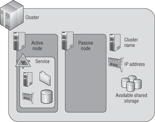
Figure 7.1 The components of a failover cluster
A One-Node Cluster?
I stated that a cluster consists of two or more nodes, but strictly speaking, that is not accurate. A cluster can consist of a single node, and many times you may start with a one-node cluster. Remember, the point of a cluster is to provide high availability of services by enabling services to move between servers if a server fails. With a single-node cluster, if the node fails, there is nowhere for the services to move to. Therefore, you always want at least two nodes in a cluster to provide high availability services.
This does not mean you won't ever see a single-node cluster. There are some features of failover clustering that apply even to single-node environments, such as the ability to monitor services that run inside virtual machines and restart the virtual machine if a service fails three times.
Figure 7.1 shows an active node and a passive node. In the example there is a single service configured in the cluster. The node the service is running on is the active node. The node not running the service is the passive node, but it would become the active node if the service moved to it as part of a planned move or if the existing active node failed.
While we will talk about active and passive nodes, in reality we can configure multiple services and applications within a cluster that can be hosted on different nodes in the cluster, and so at any time every node may be running a specific server or application. You just need to ensure that the resources in the cluster nodes is sufficient to run the services and applications from other nodes in the cluster in the event of planned failover of services or server failure or if applications are stopped for maintenance purposes.
The cluster consists of a number of nodes that can be active or passive. An active node is simply a node that currently owns a service or application. Windows Server 2012 allows up to 64 nodes in a cluster, up from the 16 nodes in previous versions of Windows Server.
A cluster can contain multiple services and applications, and these can be spread among all the nodes in the cluster. A service or application consists of a number of resources that enable the service or application to function, such as, for example, a disk resource, a share, a name, and an IP address. Different types of services and applications use different resources.
Any resource that is cluster aware and hosted in a cluster can move between nodes in the cluster to increase its availability. In an unplanned failure, such as a node failing, there may be a small period of service interruption because the node failure must be detected and then the service's resources moved to another node and restarted. In most planned scenarios, such as moving resources from one node to another to enable maintenance on the source node, any outage can be avoided, such as using Live Migration when a Hyper-V virtual machine moves between nodes in a cluster.
If you used clustering prior to Windows Server 2008, then you will have experienced an extremely long and painful cluster creation process that required pages of configuration information, was hard to troubleshoot, and required special hardware from a cluster-specific hardware compatibility list. This completely changed with Windows Server 2008. Windows Server 2008 introduced a greatly simplified cluster creation process that required you to specify only the nodes to be added to the cluster and to provide a name for the cluster and an IP address if DHCP was not used. All the other details are automatically configured by the cluster setup wizard. Additionally, the separate cluster hardware compatibility list was removed, replaced with a new cluster validation process that is run on the desired nodes prior to cluster creation. If the cluster validation passes, the cluster will be supported by Microsoft.
Understanding Quorum and Why It's Important
With a cluster, there are multiple nodes that share a common cluster database in which services are defined that can run on any node in the cluster. The goal of the cluster is to provide high availability so if something bad happens on a node, the services move to another node. What is important is that there are scenarios where it may be a network problem that stops different parts of a cluster from being able to communicate rather than actual node problems. In the case of a communication problem between different parts (partitions) of the cluster, only one part of the cluster should run services to avoid the same service starting on different parts of the cluster, which could then cause corruption.
The detection of “something bad” happening within a cluster is facilitated by cluster heartbeat communications. The nodes in the cluster communicate constantly via a heartbeat to ensure that they are available. In the event of a change of cluster status, such as a node becoming unavailable or network problems stopping the cluster nodes from communicating, the cluster goes into arbitration, which is where the remaining nodes basically fight out to decide who should be hosting which services and applications to avoid split-brain. Split-brain describes a situation in which multiple nodes in a cluster try to bring online the same service or application, which causes the nodes to try to bring online the same resources.
Quorum Basics
Quorum is the mechanism used to ensure that in the event of a break in communication between parts of the cluster or the loss of parts of the cluster, we always have to have a majority of cluster resources for the cluster to function. Quorum is the reason it is common to have a shared disk or file share that can be used in arbitration when there is an even number of nodes in different parts of the cluster.
Imagine that we had a cluster of four nodes without any shared disk or file share used for quorum and arbitration. If a split occurred and for some reason each node could contact only the node next to it, each half of the cluster would have two nodes, which would be a disaster because both halves may think they should own all the services and applications. That is why the quorum model is based on a majority, that is, more than half is needed for the cluster to function. In our example of two nodes on each side, neither side would have majority (half is not majority), so no cluster resources would be serviced. This is far better than multiple nodes trying to service the same resources. In actual fact, the behavior in the scenario I just outlined, with exactly half the nodes in each partition of the cluster, has changed in Windows Server 2012 R2, so services would be offered by one of the partitions. Each node can be seen as having a vote. By adding an extra vote with a file share or disk, you can ensure that one part of the cluster can always get more than 50 percent by claiming the file share or disk vote.
Let's look in detail at quorum. Prior to Windows Server 2012 there were a number of different quorum models, and even with Windows Server 2012 there was specific guidance about when to use a file share witness or disk witness. In Windows Server 2012 R2, this has all changed.
Prior to Windows Server 2012, there were various different cluster models, but in Windows Server 2012, this has been simplified to a single model. Within a cluster, by default each node has a vote. These votes are used in times of arbitration to decide which partition of a cluster can make quorum, that is, has more than half the number of votes. When creating a cluster, you also define either a disk witness or a file share witness, which also has a vote. Prior to Windows Server 2012 R2, a file share witness or disk witness was configured only if you had an even number of nodes. That meant an even number of votes, and therefore, in the event of partitioning of the cluster, neither partition would have more votes than the other side because there is an even number of nodes. When you configure the file share witness or disk witness, the extra vote assured that one partition of the cluster could claim that vote and therefore have more than 50 percent of the votes and make quorum. Only when the witness is required to make quorum is it locked by one partition of the cluster. For a file share witness, the lock is performed by locking the witness.log file on the share by one of the cluster partitions. To lock a disk witness, the disk has a SCSI persistent reservation made by one of the partitions. Both types of locks stop another partition of the cluster from being able to take ownership of the witness and try to use its vote to make quorum. This is shown in Figure 7.2 along with an odd number of vote scenarios showing why the witness is not required.
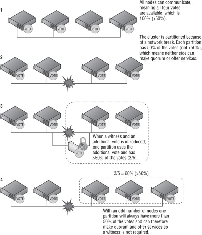
Figure 7.2 Quorum in a failover cluster
Windows Server 2012 R2 changed the recommendation to always configure the disk witness or file share witness. It enhances the dynamic quorum feature introduced in Windows Server 2012 to extend to the additional witness to give it a vote only if there are an even number of nodes. If there are an odd number of nodes, then the witness does not get a vote and is not used.
A file share witness is simply a share on an SMB file server that is running Windows Server 2003 or above and is on a node that is in the same forest as the cluster. The file share should not be hosted on the actual cluster. If you have a multisite cluster, host the file share witness on a server in a third site to avoid any dependence on one of the two sites used by the cluster. A single file server can host file shares for different clusters. The cluster object in Active Directory (Cluster Name Object, or CNO) must have full control on both the file share and the folder that the file share is sharing. A good naming convention to use to avoid confusion for the share is FSW_<Cluster Name>. It's actually possible to have the file share witness for a cluster hosted on a different cluster to provide additional resiliency to the file share. Note that the clustered file share can be hosted on a traditional file server or a scale-out file server. Both will work well.
A disk witness can be any cluster disk, which means it's accessible from all nodes in a cluster that is NTFS or Resilient File System (ReFS) formatted and is at least 512 MB in size. You may wonder why the cluster disk needs to be 512 MB in size. The cluster disk stores a copy of the cluster database, hence the size requirement. By default, when you're creating a cluster, the smallest cluster disk that is over 512 MB is automatically made the disk witness, although this can be changed. The disk witness is exclusively used for witness purposes and does not require a drive letter.
To modify the witness configuration for a cluster, perform the following steps:
1. In Failover Cluster Manager, select the main cluster object in the navigation pane.
2. From More Actions, select Configuration Cluster Quorum Settings.
3. Click Next on the introduction page of the wizard.
4. Select the Select The Quorum Witness option and click Next. Note also the option Use Default Quorum Configuration, which allows the cluster to automatically configure witness configuration as it would during the initial cluster creation process.
5. Select the option to use a disk witness, file share witness, or no witness (never recommended) and click Next.
6. Depending on the option selected, you now must select the disk witness or file share. Then click Next.
7. Click Next on the remaining pages to complete the quorum configuration.
This can also be configured using PowerShell with one of the following commands depending on your desired quorum configuration:
· Set-ClusterQuorum -NoWitness (Don't do this.)
· Set-ClusterQuorum -DiskWitness “<disk resource name>”
· Set-ClusterQuorum -FileShareWitness “<file share name>”
· Set-ClusterQuorum -DiskOnly “<disk resource name>” (Don't do this either.)
File Share Witness and a Disk Witness? Which One?
You never want two additional votes. The entire point of the witness vote is to provide an additional vote where there are an even number of votes caused by an even number of nodes.
You can make a decision as to whether is it better to have a disk witness or a file share witness. If you have a multisite cluster, then most likely you will have to use a file share witness because there would not be shared storage between the two sites. Additionally, the file share witness should be placed in a third site to provide protection from a site failure.
In a cluster where shared storage is available, always use a disk witness over a file share cluster, and there is a very good reason for this.
When you use a file share witness, a folder is created on the file share named with the GUID of the cluster, and within that folder a file is created that is used in times of arbitration so only one partition of a cluster can lock the file. Also, the file shows a time stamp of the last time a change was made to the main cluster database, although the file share does not actually have a copy of the cluster database. Every time a change is made to the cluster database, the time stamp on the file share witness is updated but the actual data is not stored on the file share witness, making the amount of actual network traffic very light.
Consider a scenario of a two-node cluster, node A and node B. If node A goes down, node B keeps running and makes updates to the cluster database, such as adding new resources, and also updates the time stamp of the witness.log on the file share witness. Then node B goes down and node A tries to start. Node A would see that the time stamp on the file share witness is in advance of its own database and realize its cluster database is stale and so will not start the cluster service. This prevents partition-in-time from occurring because node A is out-of-date (which is a good thing because you don't want the cluster to start out-of-date) and you would have different cluster states on different nodes, but you can't start the cluster without node B coming back or forcing quorum on node A.
Now consider a disk witness that actually stores a complete copy of the cluster database. Every time a change is made to the cluster database, that change is also made to the copy of the cluster database on the disk witness.
Now in the same two-node cluster scenario, when node A tries to start and sees that its database is out-of-date, it can just copy the cluster database from the disk witness, which is kept up-to-date, so while a file share witness prevents partition-in-time from occurring, a disk witness solves partition-in-time.
For this reason, always use a disk witness over a file share witness if possible.
As can be seen, the number of votes is key for cluster quorum, specifically having more than 50 percent of the total number of votes, but the total number of votes can be a problem. Traditionally, the number of votes is set when the cluster is created, when the quorum mode is changed, or when nodes are added or removed from the cluster. For any cluster, the total number of votes is a hard number that can be changed only through one of the actions previously mentioned. Problems can occur though. Consider a five-node cluster with no witness configured, which means there are five possible votes and three votes must be available for the cluster to make quorum. Consider the following sequence of actions:
· An administrator performs patching on a node, which requires reboots. The node would be unavailable for a period of time and therefore its vote is not available. This leaves four out of the five possible votes available, which is greater than 50 percent, so the cluster keeps quorum.
· The administrator starts to perform maintenance on another node, which again requires reboots, losing the vote of the additional node and leaving three out of the five possible votes available. That is still greater than 50 percent, which keeps quorum and the node stays functional.
· A failure in a node occurs or the administrator is an overachiever and performs maintenance on another node, losing its vote. Now there are only two votes out of the five possible votes, which is less than 50 percent, so the cluster loses quorum, the cluster services stop on the remaining two nodes, and all services in the cluster are no longer offered.
In this scenario, even though planned maintenance was going on and even though there were still two healthy nodes available, the cluster could no longer make quorum because there were less than 50 percent of the votes available. The goal of clustering is to increase availability of services, but in this case it actually caused services to become unavailable.
Windows Server 2012 changed how the vote allocation works and cures the scenario just described with a feature called dynamic quorum. With dynamic quorum, the total number of votes available in the cluster changes as node states change; for example, if a node is taken down as part of maintenance, then the node removes its vote from the cluster, reducing the total number of votes in the cluster. When the node comes out of maintenance, it adds its vote back, restoring the total number of possible votes to the original value. This means the cluster has greater resiliency when it comes to problems caused by a lack of votes. Consider the preceding scenario in Windows Server 2012 with dynamic quorum:
· An administrator performs patching on a node, which requires reboots, so the node would be unavailable for a period of time. As the node goes in to maintenance mode, it removes its vote from the cluster, reducing the total number of votes from five to four.
· The administrator starts to perform maintenance on another node, which again requires reboots. The node removes its vote, reducing the total number of votes in the cluster to three.
· A failure in a node occurs or the administrator is an overachiever and performs maintenance on another node, losing its vote. Now there are only two votes left out of the three total votes, which is greater than 50 percent, so the cluster stays running! In actual fact, that node that is now unavailable will have its vote removed from the cluster by the remaining nodes.
The dynamic quorum feature may seem to possibly introduce a problem to clustering, considering the whole point of the votes and quorum is to protect the cluster from becoming split-brain, with multiple partitions offering services at the same time. With dynamic quorum in place and votes being removed from the cluster when nodes go into maintenance or fail, you may think, “Couldn't the cluster split and both parts make quorum?” The answer is no. There are still rules for how dynamic quorum can remove votes and keep quorum.
To be able to deterministically remove the vote of a cluster node, the remaining nodes must have quorum majority. For example, if I had a three-node cluster and one of the nodes fails, the remaining two nodes have quorum majority, two out of three votes, and therefore are able to remove the vote of the failed node, which means the cluster now has two votes. Let's go back to our five-node cluster, which experiences a network failure. One partition has three nodes and the other partition has two nodes. The partition with three nodes has quorum majority, which means it keeps offering services and can therefore remove the votes of the other two nodes. The partition with two nodes does not have quorum majority, so the cluster service will shut down. The partition with three nodes now has a total vote count of three, which means that partition can now survive one of the three nodes failing, whereas without dynamic quorum, another node failure would have caused the cluster to shut down. This is shown in Figure 7.3.
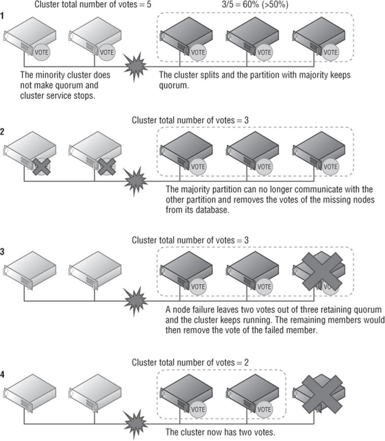
Figure 7.3 Dynamic quorum in action
With the ability to remove votes from the cluster as nodes fail or are shut down in a planned manner, it is now possible to go from a 64-node cluster all the way down to a single node, known as last man standing, providing the node shutdowns are sequential and a majority quorum is maintained with simultaneous node removals. It is important to note that if you remove a large number of nodes from a cluster, it is unlikely the remaining nodes would be able to run all the services present in the cluster unless you had a highly underutilized cluster. Dynamic quorum is enabled by default, and the recommendation is to leave it enabled. Dynamic quorum is a cluster property, and if you wanted to disable it, this is done through PowerShell by setting the cluster DynamicQuorum property to 0 instead of the default 1, as in (Get-Cluster).DynamicQuorum = 0. Note that as nodes are resumed/fixed and communication is restored, the nodes votes are restored to the cluster. To summarize the dynamic quorum scenarios:
· When a node shuts down in a planned manner (an administrator shutdown or automated shutdown such as cluster-aware updating), the node removes its own vote.
· When a node crashes, the remaining active nodes remove the vote of the downed node.
· When a node joins the cluster, it gets its vote back.
There is a feature called Node Vote Weights that actually enables certain nodes to be specified as not participating in quorum calculations by removing the vote of the node. The node still fully participates in the cluster, it still has a copy of the cluster database, and it still runs cluster services and can host applications, it simply no longer affects quorum calculations. There is really only one scenario where you would want to make this type of change, and that is for multisite clusters where failover must be manually performed, such as with a SQL Always On High Availability configuration using asynchronous replication that requires manual interaction to failover. In this scenario, the nodes in the remote site would have their votes removed so they cannot affect quorum in the primary site.
Modifying Cluster Vote Configuration
Modification of votes can be performed using the Failover Cluster Manager graphical interface and PowerShell. To modify votes using the graphical tools, perform the following steps (note that the same process can be used to revert the cluster back to the default configuration of all nodes having votes):
1. In Failover Cluster Manager, select the main cluster object in the navigation pane.
2. From More Actions, select Configuration Cluster Quorum Settings.
3. Click Next on the introduction screen of the wizard.
4. Select the Advanced Quorum Configuration option and click Next.
5. On the Select Voting Configuration page, choose the Select Nodes option and then uncheck the nodes that should not have a vote and click Next (Figure 7.4). Note that on this screen, the default is All Nodes, meaning all nodes should have a vote, but also there is an option that no nodes have a vote, which means that only the disk witness has a vote. This is the original cluster quorum model and frankly, it should never be used today because it introduces a single point of failure. It is there for historical reasons only.
6. Click Next to all remaining screens. The witness configuration will be changed and the modification will then be made to the cluster.
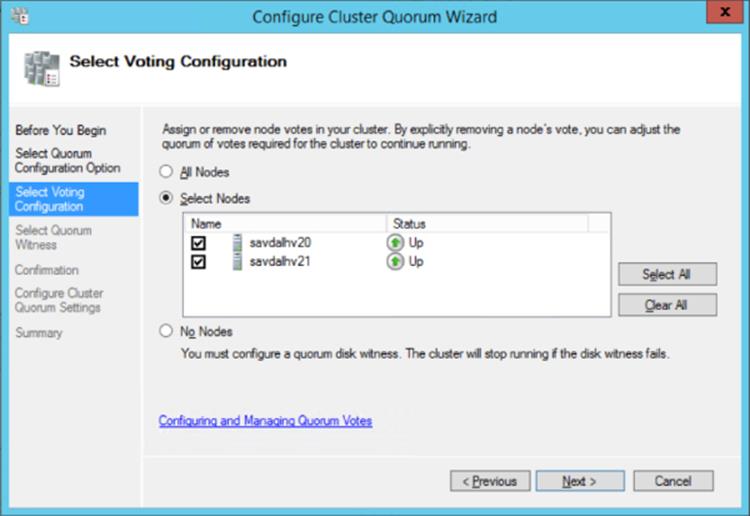
Figure 7.4 Changing the votes for nodes in a cluster
To make the change using PowerShell, set the vote of the node to 0 (instead of the default value of 1), as in this example:
(Get-ClusterNode <name>).NodeWeight=0
To view the current voting state of nodes in a cluster, use the Nodes view within Failover Cluster Manager as shown in Figure 7.5. Note that two values are shown. The administrator-configured node weight is shown in the Assigned Vote column, while the cluster-assigned dynamic vote weight as controlled by dynamic quorum is shown in the Current Vote column. If you run a cluster validation, the generated report also shows the vote status of the nodes in the cluster. Remember, only use the node vote weighting in the very specific geo-cluster scenarios where manual failover is required. In most scenarios, you should not manually change the node weights.
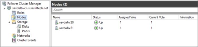
Figure 7.5 Viewing the current voting state of a cluster
Earlier in this chapter I explained that in Windows Server 2012 R2, the guidance is to always configure a witness for the cluster. This is because the dynamic quorum technology has been extended to the witness in Windows Server 2012 R2; this technology is known as dynamic witness. Failover clustering is now smart enough to decide if the witness should have a vote or not:
· If there are an even number of nodes that have a vote (dynamic weight = 1), the witness dynamic vote = 1.
· If there are an odd number of nodes that have a vote (dynamic weight = 1), the witness dynamic vote = 0.
This is very logical because the witness is only needed when there is an even number of nodes, which ordinarily would not be able to make quorum in the event of a split. If the witness goes offline or fails, its witness dynamic vote value will be set to 0 in the same manner a failed nodes vote is removed. To check if the witness currently has a vote, run the following PowerShell command:
(Get-Cluster).WitnessDynamicWeight
A return value of 1 means the witness has a vote; a return value of 0 means the witness does not have a vote. If you look at the nodes in the cluster, the witness vote weight should correlate to the dynamic votes of the cluster nodes. To check the dynamic votes of the cluster nodes from PowerShell, use the following:
PS C:\> Get-ClusterNode | ft Name, DynamicWeight -AutoSize
Name DynamicWeight
---- -------------
savdalhv20 1
savdalhv21 1
Advanced Quorum Options and Forcing Quorums
In all of the quorum explanations so far, the critical factor is that there must be a majority of votes available for the cluster to keep running, greater than 50 percent. There will be times when there are an even number of votes in the cluster due to other failures (although dynamic witness should help avoid ever having an even number of votes unless it's the witness that has failed) or misconfiguration. Windows Server 2012 R2 provides tie-breaker code so that the cluster can now survive a simultaneous loss of 50 percent of the votes while ensuring that only one partition keeps running and the other partition shuts down. In the event of the loss of 50 percent of the votes, clustering will automatically select one of the partitions to “win” using a specific algorithm. The way the winning partition is selected is as follows: If there are an even number of node votes in the cluster, the clustering service will randomly select a node and remove its vote. That will change the number of votes in the cluster to odd again, giving one of the sites a majority vote and therefore making it capable of surviving a break in communication. If you want to control which of the sites should win if there is a break of communication, a cluster attribute, LowerQuorumPriorityNodeId, can be set to the ID of the node that should lose its vote when there are an even number of nodes and no witness available. Remember, providing you have configured a witness, this functionality should not be required.
Even in single-site configurations, the same last man standing code will be implemented. If I have a single site with only two nodes left in the cluster and no witness, one of the nodes would lose its vote. I want to look in more detail at this “last two vote standing” scenario as shown in Figure 7.6, which continues with the scenario we looked at in Figure 7.3. Note that in this example, there is no witness, which would not be best practice.
· If node B now has a failure, the cluster continues running on node A because node A has the last remaining vote and has quorum majority (it has the single vote, so it has 100 percent of the vote and therefore >50 percent).
· If node A has a failure and shuts down, then node B's cluster service will stop because node A had the only vote and therefore node B has no vote and cannot make quorum.
· If a communication failure happens between node A and node B, then node A will keep running with quorum majority while node B's cluster service will stop.
· If node A shuts down cleanly, then before it shuts down it will transfer its vote to node B, which means the cluster will continue running on node B.
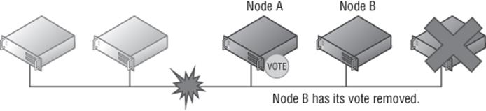
Figure 7.6 Two remaining nodes in a cluster
With all these new technologies, it's actually very hard for the cluster to lose quorum. To lose quorum, the cluster would have to simultaneously lose more than half the number of votes, in which case you should shut down the cluster to protect the integrity of the services.
This brings us to forcing quorum. Consider a remote site that has a minority number of votes but in a disaster the cluster service must be started. Even in normal circumstances there may be times when nodes are lost and the cluster service must be started even without quorum majority. This is known as Forced Quorum, and it allows the cluster to start without a majority of votes. When a cluster is started in Forced Quorum mode, it stays in that mode until a majority of nodes is available as they come online again, at which point the cluster automatically switches from Forced Quorum mode to the normal mode. To start the cluster in Forced Quorum mode, perform one of the following on one node that will be part of the Forced Quorum partition:
· Run the command Start-ClusterNode -ForceQuorum.
· Run the command Net start clussvc /ForceQuorum.
· Perform a force start in Failover Cluster Manager.
All other nodes that will be part of the Forced Quorum should be started in Prevent Quorum mode, which tells the nodes it must join an existing cluster, preventing different nodes from creating their own partitions using one of the following methods:
· Run the command Start-ClusterNode -PreventQuorum.
· Run the command Net start clussvc /PQ.
· If you used the Failover Cluster Manager to perform a force start, then no action is required on other nodes. When you Force Quorum through the management tool, one node is picked to start with Force Quorum and then all other nodes that can be communicated with will be started with Prevent Quorum.
Windows Server 2012 R2 introduces Force Quorum resiliency, which is important when Force Quorum is used. Consider Figure 7.7, which shows how the cluster works when Forced Quorum is used. Step 1 shows that the partition with two nodes is started with Force Quorum. In step 2, the other partition starts and makes quorum because it has three out of five votes, so it has majority but no communication to the partition that started with Force Quorum. In step 3, the communication is restored and the partition with three nodes detects a partition that was started with Force Quorum. At this point, the three-node partition restarts the cluster service in Prevent Quorum mode on all nodes, which forces them to join the Force Quorum partition. In step 4, the merged cluster now has quorum majority and exits Force Quorum mode.
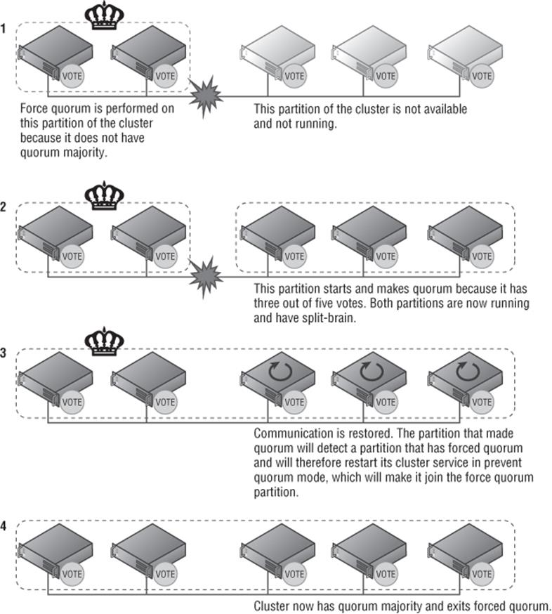
Figure 7.7 Force quorum resiliency in action
Care should be taken when using Forced Quorum because it would potentially be possible to start the cluster service on multiple cluster partitions, which could cause big problems. Make sure you understand what is happening within the cluster that has caused the cluster to lose quorum and be 100 percent positive that the cluster is not running in another location before performing Forced Quorum.
Geographically Distributed Clusters
With enhancements to networking, storage, and particularly failover clustering in Windows Server, it is much easier to have multisite clusters and many of the quorum features discussed previously can be very useful. The first decision that must be made when dealing with a multisite environment is how the switch of services between sites should be performed.
If the failover between sites is automatic, then the sites can be considered equal. In that case, it's important to use a file share witness in a third location to ensure that if one site fails, the other site can use the witness vote and make quorum and offer services. If you have a synchronous storage replication solution that supports arbitration of storage, a disk witness could be used, but this is rare, which is why in most cases a file share witness would be used. It is important that both sites have an equal number of nodes. You would need to leverage a technology to replicate the storage used by Hyper-V virtual machines to the other location. If this type of SAN replication of storage is not available, the Hyper-V Replica technology can be leveraged. However, this would actually require separate clusters between locations and would not be an automated failover.
Can I Host My File Share Witness in Windows Azure IaaS?
Windows Azure IaaS enables virtual machines to run in the Windows Azure cloud service, which can include a file server offering a file share that can be domain joined, making it seem a plausible option to host the witness for a cluster.
Technically the answer is that the file share for a cluster could be hosted in a Windows Azure IaaS VM and the Windows Azure virtual network can be connected to your on-premises infrastructure using its site-to-site gateway functionality. In most cases it would not be practical because most likely the desire to use Windows Azure is because you have two datacenters hosting nodes and wish to use Windows Azure as the “third site.” The problem is, at the time of this writing, a Windows Azure virtual network supports only a single instance of the site-to-site gateway, which means it could be connected to only one of the datacenters. If the datacenter that the virtual network was connected to failed, the other datacenter would have no access to Windows Azure and therefore would not be able to see the file share witness, use its vote, and make quorum, making it fairly useless. Once Windows Azure supports multiple site-to-site gateways, then using it for the file share witness would become a more practical solution.
The other options is a manual failover where services are manually activated on the disaster recovery site. In this scenario, it would be common to remove votes from the disaster recovery site so it does not affect quorum on the primary location. In the event of a failover to the disaster recovery location, the disaster recovery site would be started in a Force Quorum mode.
In reality, it is not that common to see stretched clusters for Hyper-V virtual machines because of the difficulty and high expense of replicating the storage. Additionally, if virtual machines moved between locations, most likely their IP configuration would require reconfiguration unless network virtualization was being used or VLANs were stretched between locations, which again is rare and can be very expensive. In the next chapter, I will cover Hyper-V Replica as a solution for disaster recovery, which solves the problems of moving virtual machines between sites. Multisite clusters are commonly used for application workloads such as SQL and Exchange instead of for Hyper-V virtual machines.
Why Use Clustering with Hyper-V?
In the previous sections I went into a lot of detail about quorum and how clusters work. The key point is this: clusters help keep the workloads available with a minimal amount of downtime, even in unplanned outages. For Hyper-V servers that are running many virtual machines, keeping the virtual machines as available as possible is critical.
When looking at high availability, there are two types of outage: planned and unplanned. A planned outage is a known and controlled outage, such as, for example, when you are rebooting a host to apply patches or performing hardware maintenance or even powering down a complete datacenter. In a planned outage scenario, it is possible to avoid any downtime to the virtual machines by performing a Live Migration of the virtual machines on one node to another node. When Live Migration is used, the virtual machine is always available to clients.
An unplanned outage is not foreseen or planned, such as, for example, a server crash or hardware failure. In an unplanned outage, there is no opportunity to perform Live Migration of virtual machines between nodes, which means there will be a period of unavailability for the virtual machines. In an unplanned outage scenario, the cluster will detect that a node has failed and the resources that were running on the failed node will be redistributed among the remaining nodes in the cluster and then started. Because the virtual machines were effectively just powered off without a clean shutdown of the guest OS inside the virtual machines, the guest OS will start in what is known as a “crash consistent state,” which means when the guest OS starts and applications in the guest OS start, there may be some consistency and repair actions required.
In Windows Server 2008 R2, the Live Migration feature for moving virtual machines with no downtime between servers was available only between nodes in a cluster because the storage had to be available to both the source and target node. In Windows Server 2012, the ability to live migrate between any two Hyper-V 2012 hosts was introduced. It's known as Shared Nothing Live Migration, and it migrates the storage in addition to the memory and state of the virtual machine.
One traditional feature of clustering was the ability to smoothly move storage between nodes in a cluster. It was enhanced greatly with Windows Server 2008 R2 to actually allow storage to be shared between the nodes in a cluster simultaneously; it's known as Cluster Shared Volumes (CSV). With CSV, an NTFS volume can be accessed by all the nodes at the same time, allowing virtual machines to be stored on a single NTFS-formatted LUN and run on different nodes in the cluster. The sharing of storage is a huge feature of clusters and makes the migration of virtual machines between nodes a much more efficient process because only the memory and state of the virtual machine needs to be migrated and not the actual storage. Of course, in Windows Server 2012, nodes not in a cluster can share storage by accessing a common SMB 3 file share, but many environments do not have the infrastructure to utilize SMB 3 at a datacenter level or already have large SAN investments.
As can be seen, some of the features of clustering for Hyper-V are now available outside of a cluster at some level, but not with the same level of efficiency and typically only in planned scenarios. Additionally, a cluster provides a boundary of host membership, which can be used for other purposes, such as virtual machine rebalancing, placement optimization, and even automation processes such as cluster patching. I will be covering migration, CSV, and the other technologies briefly mentioned in detail later in this chapter.
Clustering brings high availability solutions to unplanned scenarios, but it also brings some other features to virtual machine workloads. It is because of some of these features that occasionally you will see a single-node cluster of virtual machines. Hyper-V has a number of great availability features, but they are no substitute for clustering to maintain availability during unplanned outages and to simplify maintenance options, so don't overlook clustering.
Service Monitoring
Failover clustering provides high availability to the virtual machine in the event of a host failure, but it does not provide protection or assistance if a service within the virtual machine fails. Clustering is strictly making sure the virtual machine is running; it offers no assistance to the operating system running within the virtual machine.
Windows Server 2012 clustering changed this by introducing a new clustering feature, service monitoring, which allows clustering to communicate to the guest OS running within the virtual machine and check for service failures. If you examine the properties of a service within Windows, there are actions available if the service fails, as shown in Figure 7.8. Note that in the Recovery tab, Windows allows actions to be taken on the first failure, the second failure, and then subsequent failures. These actions are as follows:
· Take No Action
· Restart The Service
· Run A Program
· Restart The Computer
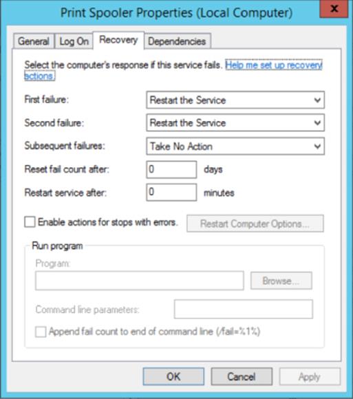
Figure 7.8 Service retry actions
Consider if a service fails three times consecutively; it's unlikely restarting it a third time would result in a different outcome. Clustering can be configured to perform the action that is known to fix any problem, reboot the virtual machine on the existing host. If the virtual machine is rebooted by clustering and the service fails a subsequent time inside the virtual machine, then clustering will move the virtual machine to another host in the cluster and reboot it.
For this feature to work, the following must be configured:
· Both the Hyper-V servers must be Windows Server 2012 and the guest OS running in the VM must be Windows Server 2012.
· The host and guest OSs are in the same or at least trusting domains.
· The failover cluster administrator must be a member of the local administrator's group inside the VM.
· Ensure that the service being monitored is set to Take No Action (see Figure 7.8) within the guest VM for subsequent failures (which is used after the first and second failures) and is set via the Recovery tab of the service properties within the Services application (services.msc).
· Within the guest VM, ensure that the Virtual Machine Monitoring firewall exception is enabled for the Domain network by using the Windows Firewall with Advanced Security application or by using the following Windows PowerShell command:
Set-NetFirewallRule -DisplayGroup "Virtual Machine Monitoring" -Enabled True
After everything in the preceding list is configured, enabling the monitoring is a simple process:
1. Launch the Failover Cluster Manager tool.
2. Navigate to the cluster and select Roles.
3. Right-click the virtual machine role you wish to enable monitoring for, and under More Actions, select Configure Monitoring.
4. The services running inside the VM will be gathered by the cluster service communicating to the guest OS inside the virtual machine. Check the box for the services that should be monitored, as shown in Figure 7.9, and click OK.
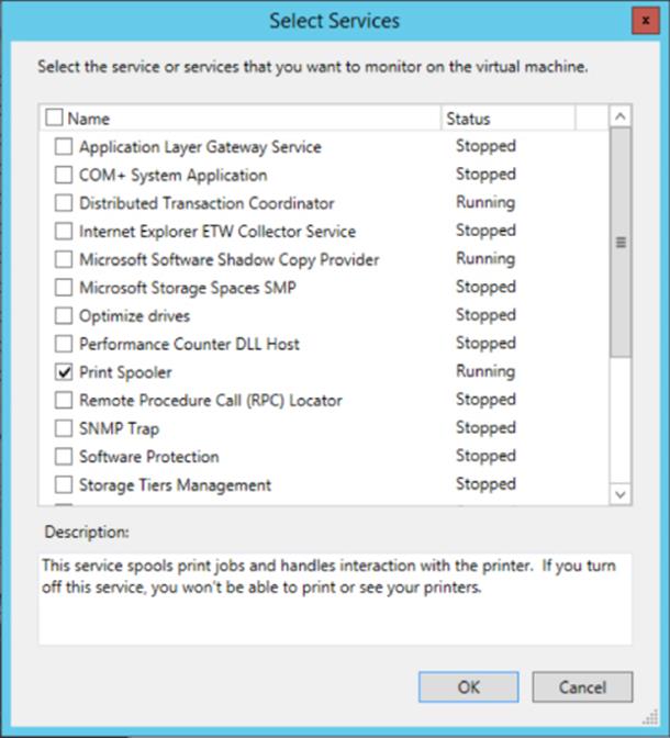
Figure 7.9 Enabling monitoring of a service
Monitoring can also be enabled using the Add-ClusterVMMonitoredItem cmdlet and -VirtualMachine, with the -Service parameters, as in this example:
PS C:\ > Add-ClusterVMMonitoredItem -VirtualMachine savdaltst01 -Service spooler
After two service failures, an event ID 1250 is logged in the system log. At this point, the VM will be restarted, initially on the same host, but on subsequent failures it will restart on another node in the cluster. This process can be seen in a video athttp://youtu.be/H1EghdniZ1I.
This is a very rudimentary capability, but it may help in some scenarios. As mentioned in the previous chapter, for a complete monitoring solution, leverage System Center Operations Manager, which can run monitoring with deep OS and application knowledge that can be used to generate alerts. Those alerts can be used to trigger automated actions for remediation or simply to generate incidents in a ticketing system.
Protected Network
While the operating system and applications within virtual machines perform certain tasks, the usefulness of those tasks is generally being able to communicate with services via the network. If the network is unavailable on the Hyper-V host that the virtual machine uses, traditionally clustering would take no action, which has been a huge weakness. As far as clustering is aware, the virtual machine is still fine; it's running with no problems. Windows Server 2012 R2 introduces the concept of a protected network to solve this final gap in high availability of virtual machines and their connectivity.
The Protected Network setting allows specific virtual network adapters to be configured as protected, as shown in Figure 7.10, via the Settings option of a virtual machine and the Advanced Features options of the specific network adapter. In the event the Hyper-V host loses network connectivity that the virtual machine network adapters configured as a protected network are using, the virtual machines will be live migrated to another host in the cluster that does have network connectivity for that network. This does require that the Hyper-V host still have network connectivity between the Hyper-V hosts to allow Live Migration, but typically clusters will use different networks for virtual machine connectivity than those used for Live Migration purposes, which means Live Migration should still be possible.
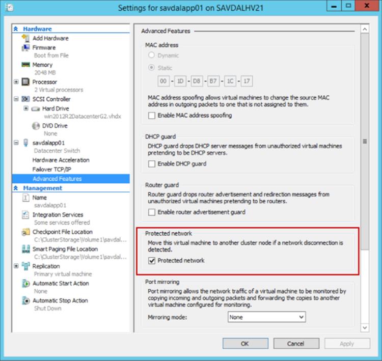
Figure 7.10 Configuring a protected network on a virtual machine network adapter
It is important to try to provide as much resiliency as possible for network communications, which means using NIC teaming on the hosts as described Chapter 3, “Virtual Networking,” but the protected network features provides an additional layer of resiliency to network failures.
Cluster-Aware Updating
Windows Server 2012 placed a huge focus on running the Server Core configuration level, which reduced the amount of patching and therefore reboots required for a system. There will still be patches that need to be installed and therefore reboots, but the key point is to reduce (or ideally, eliminate) any impact to the virtual machines when hosts have to be rebooted.
In a typical cluster, any impact to virtual machines is removed by Live Migrating virtual machines off of a node, patching and rebooting that node, moving the virtual machines back, and repeating for the other nodes in the cluster. This sounds simple, but for a 64-node cluster, this is a lot of work.
SCVMM 2012 introduced the ability to automate the entire cluster patching process with a single click, and this capability was made a core part of failover clustering in Windows Server 2012. It's called Cluster-Aware Updating. With Cluster-Aware Updating, updates are obtained from Microsoft Update or an on-premises Windows Server Update Services (WSUS) implementation and the entire cluster is patched with no impact to availability of virtual machines.
I walk through the entire Cluster-Aware Updating configuration and usage at the following location:
http://windowsitpro.com/windows-server-2012/cluster-aware-updating-windows-server-2012
Where to Implement High Availability
With the great features available with Hyper-V clustering, it can be easy to think that clustering the Hyper-V hosts and therefore providing high availability for all the virtual machines is the only solution you need. Clustering the Hyper-V hosts definitely provides great mobility, storage sharing, and high availability services for virtual machines, but that doesn't mean it's always the best solution.
Consider an application such as SQL Server or Exchange. If clustering is performed only at the Hyper-V host level, then if the Hyper-V host fails, the virtual machine resource is moved to another host and then started in a crash consistent state, which means the service would be unavailable for a period of time and likely an amount of consistency checking and repair would be required. Additionally, the host-level clustering will not protect from a crash within the virtual machine where the actual service is no longer running but the guest OS is still functioning, and therefore no action is needed at the host level. If instead guest clustering was leveraged, which means a cluster is created within the guest operating systems running in the virtual machines, the full cluster-aware application capabilities will be available, such as detecting if the application service is not responding on one guest OS, allowing another instance of the application to take over. Guest clustering is fully supported in Hyper-V virtual machines, and as covered Chapter 4, “Storage Configurations,” there are numerous options to provide shared storage to guest clusters, such as iSCSI, Virtual Fibre Channel, and shared VHDX.
The guidance I give is as follows:
· If the application running inside the virtual machine is cluster aware, then create multiple virtual machines, each with the application installed, and create a guest cluster between them. This will likely mean enabling some kind of shared storage for those virtual machines.
· If the application is not cluster aware but works with technologies such as Network Load Balancing (NLB), for example IIS, then deploy multiple virtual machines, each running the service, and then use NLB to load balance between the instances.
· If the application running inside the virtual machine is not cluster aware or NLB supported but multiple instances of the application are supported and the application has its own methods of distributing load and HA (for example, Active Directory Domain Services), then deploy multiple instances over multiple virtual machines.
· Finally, if there is no application-native high availability option, rely on the Hyper-V cluster, which is better than nothing.
It is important to check whether applications support not only running inside a virtual machine (nearly all applications do today) but also running on a Hyper-V cluster, and extending that, whether they support being live migrated between hosts. Some applications initially did not support being live migrated for technical reasons, or they were licensed by physical processors, which meant it was expensive if you wanted to move the virtual machine between hosts because all processors on all possible hosts would have to be licensed. Most applications have now moved beyond restrictions of physical processor instance licensing, but still check!
There is another configuration you should perform on your Hyper-V cluster for virtual machines that contain multiple instances of an application (for example, multiple SQL Server VMs, multiple IIS VMs, multiple domain controllers, and so on). The goal of using multiple instances of applications is to provide protection from the VM failing or the host that is running the virtual machines failing. Having multiple instances of an application across multiple virtual machines is not useful if all the virtual machines are running on the same host. Fortunately, failover clustering has an anti-affinity capability, which ensures where possible that virtual machines in the same anti-affinity group are not placed on the same Hyper-V host. To set the anti-affinity group for a virtual machine, usecluster.exe or PowerShell:
· (Get-ClusterGroup “<VM>”).AntiAffinityClassNames = “<AntiAffinityGroupName>”
· cluster.exe group “<VM>” /prop AntiAffinityClassNames=“<AntiAffinityGroupName>”
The cluster affinity can be set graphically by using SCVMM, as shown in Figure 7.11. SCVMM uses availability set as the nomenclature instead of anti-affinity group. Open the properties of the virtual machine in SCVMM, navigate to the Hardware Configuration tab, and select Availability under the Advanced section. Use the Manage Availability Sets button to create new sets and then add them to the virtual machine. A single virtual machine can be a member of multiple availability sets.
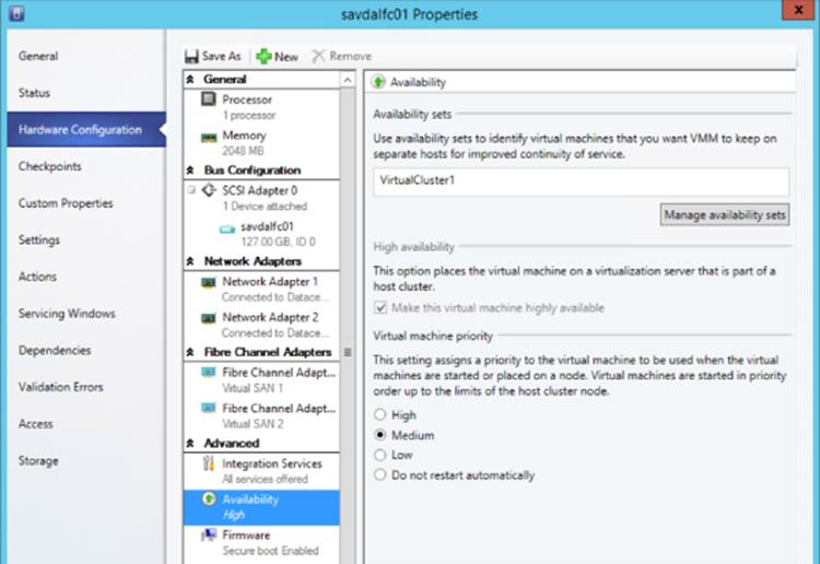
Figure 7.11 Setting affinity using SCVMM
By default, this anti-affinity solution is a soft enforcement, which means clustering will do its best to keep virtual machines in the same anti-affinity group on separate hosts, but if it has no choice, it will place instances on the same host. This enforcement can be set to hard by setting the cluster ClusterEnforcedAntiAffinity attribute to 1, but this may mean virtual machines may not be able to be started.
For virtual machines that are clustered, it is possible to set the preferred owners for each virtual machine and set the order of their preference. However, it's important to realize that just because a host is not set as a preferred owner for a resource (virtual machine), that doesn't mean the host can't still run that resource if none of the preferred owners are available. To set the preferred owners, right-click on a VM resource and select Properties, and in the General tab, set the preferred owners and the order as required.
If you want to ensure that a resource never runs on specific hosts, you can set the possible owners, and when a resource is restricted to possible owners, it cannot run on hosts that are not possible owners. This should be used with care because if no possible owners are available that are configured, the resource cannot start, which may be worse than it just not running on a nonoptimal host. To set the possible owners, you need to modify the cluster group of the virtual machine, which is in the bottom pane of Failover Cluster Manager. Right-click the virtual machine resource group and select Properties. Under the Advanced Policies tab, the possible owners are shown. If you unselect servers, then that specific virtual machine cannot run on the unselected servers.
The same PowerShell cmdlet is used, Set-ClusterOwnerNode, to set both the preferred and possible owners. If the cmdlet is used against a cluster resource (that is, a virtual machine), it sets the preferred owners. If it is used against a cluster group, it sets the possible owners.
It's common where possible to cluster the Hyper-V hosts to provide mobility and high availability for the virtual machines and create guest clusters where applications running within the virtual machines are cluster aware. This can be seen in Figure 7.12.
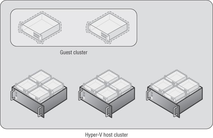
Figure 7.12 Guest cluster running within a Hyper-V host cluster
Configuring a Hyper-V Cluster
Creating a Hyper-V cluster is essentially the same process as creating any cluster running on Windows Server 2012 R2. You need to follow some general guidelines:
· Ensure that the nodes in the cluster are running the same hardware, especially for the processor. If different generations of processor are used, it may be required to configure the processor compatibility attribute on virtual machines to enable migration between hosts without downtime.
· Ensure access to shared storage to enable virtual machines to be stored on Cluster Shared Volumes.
· Network connectivity is required, such as for virtual machines and management but also for cluster communications and Live Migration. I went over the network requirements in detail in Chapter 3, but I'll review them in the next section. It is important that all nodes in the cluster have connectivity to the same networks to avoid loss of connectivity if VMs move between different servers.
· Each node must be running the same version of Windows and also should be at the same patch/service pack level.
The good news that is the process to create a cluster actually checks your potential environment through a validation process and then only if everything passes validation do you proceed and actually create the cluster. The validation process gives a lot of information and performs very in-depth checks and should be used anytime you wish to make a change to the cluster, such as, for example, adding another node. It's also possible to run the validation without any changes because it can be a great troubleshooting tool. If you experience problems or errors, run the cluster validation, which may give you some ideas of the problems. The validation process also has some checks specific to Hyper-V.
Cluster Network Requirements and Configurations
Before I go into detail on validating and creating a cluster, I want to touch on the networking requirements for a Hyper-V cluster and specifically requirements related to the cluster network.
The cluster network is critical to enable hosts in a cluster to communicate with each other. This is important for health monitoring to ensure that hosts are still running and responsive. If a server becomes unresponsive, the cluster takes remedial actions. This is done via a heartbeat that is sent by default every second over port 3343 (both UDP and TCP). This heartbeat is not a basic “ping” but rather a Request-Reply type process for the highest level of reliability and security that is actually implemented as part of the cluster NetFT kernel driver, which I will talk more about in the next section “Cluster Virtual Network Adapter.” By default, if a node does not respond to five consecutive heartbeats, it is considered down and the recovery actions are performed.
If the cluster network fails, clustering will use another network that has been configured to allow cluster communications if needed. It is important to always have at least two networks configured to allow cluster communications.
The requirements of the cluster network have changed since early versions of clustering because the cluster network is not just used for heartbeat communications but is also used for Cluster Shared Volumes communications, which now leverage SMB. The use of SMB means that the cluster network adapter must have both the Client for Microsoft Networks and File and Printer Sharing for Microsoft Networks bound, as shown in Figure 7.13. Note that you can disable the Link-Layer services because they are not required for the cluster communications.
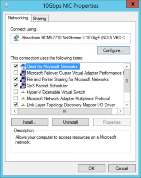
Figure 7.13 Binding for network adapters used for cluster communications
It's also important the Server and Workstation Services are running on the hosts and NTLM is used for authentication, so they must be enabled. Both IPv4 and IPv6 are supported for cluster communications, and although Microsoft performs most testing with IPv6 enabled, if it's disabled, clustering will still work fine. However, where possible leave IPv6 enabled. If both IPv4 and IPv6 are enabled, clustering will use IPv6. Disabling NetBIOS, as shown in Figure 7.14, has been shown to increase performance, and while enabling jumbo frames will not hurt, it has not been found to make any significant performance difference.
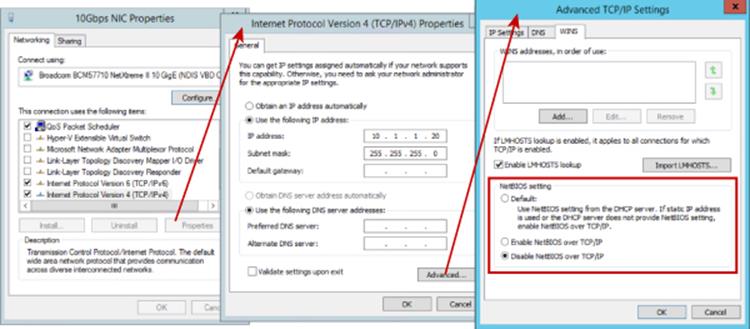
Figure 7.14 Disabling NetBIOS for the IPv4 protocol
The binding order for the network adapters in a multinetwork adapter system is very important. It tells Windows which network adapter to use for different types of communication. For example, you would not want normal management traffic trying to use the Live Migration or the cluster network. You can change the binding order for network adapters using the following steps:
1. Open the Network And Sharing Center Control Panel applet.
2. Select the Change Adapter Settings action.
3. In Network Connections, press the Alt key to see the menu and select Advanced ⇒ Advanced Settings.
4. The binding order is displayed. Make sure your management network/public network is at the top of the binding order. Your cluster networks should be at the bottom as shown in Figure 7.15.
5. Click OK to close the dialog.
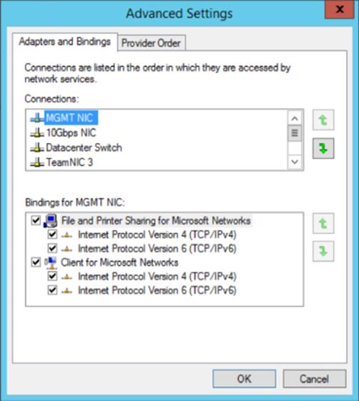
Figure 7.15 Setting the network adapter binding order
A Network Topology Generator is used to build the various cluster networks that are available to clustering. If multiple network adapters exist that are on the same IP subnet, they will automatically be grouped into the same cluster network. This is important to understand from a resiliency perspective. Imagine you place two NICs in a node, both on the same subnet, that you wish clustering to use for high availability. What will actually happen is that both NICs would be placed in the same cluster network and only one of them will be used, removing any redundancy. The correct way to achieve redundancy in this situation is to actually use NIC Teaming to join the two NICs. When you have NICs on different subnets, they will be seen as different cluster networks and then clustering can utilize them for high availability across the different network routes. If you were looking to leverage SMB multichannel, you would need to place each NIC on a different subnet, which is a cluster-specific requirement because normally SMB multichannel will work with NICs on the same subnet.
By default, during the cluster creation process, the cluster creation will use the Network Topology Generator and the most appropriate network to be used for clustering will be automatically selected based on connectivity. However, this can be changed after the cluster is created. Automatic metrics are used to determine the network used for clustering and other services based on the automatic configurations made by the cluster wizard and your customizations post creation. Figure 7.16 shows the properties available for each network available to Failover Clustering. Note that the network adapters used by Hyper-V virtual switches are not shown because they effectively offer no services to the Hyper-V host itself.
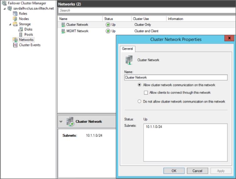
Figure 7.16 Cluster network properties
Notice that for each network, the following options are available, which are initially configured during clustering setup based on the IP configuration of the network adapter and whether a gateway was configured. These configure the role of the networks in relation to cluster activities, and they also have a numeric value, shown in square brackets.
· Allow Cluster Network Communication On This Network [1]. This is set automatically for any IP-enabled network adapter and allows the cluster to use this network if necessary unless the iSCSI Software Initiator is bound to the IP address, in which case this is not configured.
· Allow Clients To Connect Through This Network [3]. This is set automatically if the IP configuration for the network adapter has a gateway defined, which suggests external communication and therefore client communication.
· Do Not Allow Cluster Network Communication On This Network [0]. The cluster cannot use this network. This would be configured on something like an iSCSI network, which is automatically set if the iSCSI Software Initiator is bound to the IP address.
These roles can also be configured using PowerShell using this command:
(Get-ClusterNetwork "<network name>").Role=<new role number>
These three settings are used by clustering to create an automatic metric for each network adapter, which sets the priority for the preferred network to be used for cluster communications for all those available for cluster communications. The metrics can be seen using the following PowerShell:
PS C:\> Get-ClusterNetwork | ft Name, Role, AutoMetric, Metric -AutoSize
Name Role AutoMetric Metric
---- ---- ---------- ------
Cluster Network 1 True 30240
MGMT Network 3 True 70384
The lower the metric value, the cheaper it is considered to be and therefore a greater preference to be used for cluster communications. The way these values are calculated is primarily on the role of the cluster, which sets a starting value for the metric:
· Role of 1 - Starting metric 40000
· Role of 3 - Starting metric of 80000
Then the metric is reduced for each NIC based on its link speed and if it's RDMA capable and has RSS capabilities. The higher the performance and feature set of the NIC, the greater the metric reduction, making it cheaper and therefore more appealing to be used for cluster communications. It is possible to change these metric values by disabling AutoMetric on the cluster network and then manually setting a Metric value, but generally this should not be performed. Note that this prioritization of networks for cluster communications does not apply to SMB-based communications; SMB uses its own selection mechanism. If you did need to modify the metric, use the following:
(Get-ClusterNetwork "<cluster network>".AutoMetric = $false
(Get-ClusterNetwork "<cluster network>".Metric = 42
When considering network capacity planning for the network traffic, it's important to realize that in addition to the network health monitoring (heartbeats) traffic, the cluster network is used for intra-cluster communications such as cluster database updates and also CSV I/O redirection.
The heartbeat communications are very lightweight, 134 bytes to be exact in Windows Server 2012 R2, and are sent by default once a second. This means you don't require a big network pipe (that is, bandwidth), but the heartbeats are sensitive to latency (the lag between a request and response) because if too many heartbeats are not acknowledged in a period of time, the host is considered unavailable.
Intra-cluster communications type of traffic related to cluster database changes and state changes is light but does vary slightly depending on the type of workload. Our focus is Hyper-V, which has light intra-cluster communications, but a SQL or Exchange cluster tends to have a higher amount of traffic. Once again, though, the size of the pipe is not as important as the latency. This is because in the event of a cluster state change, such as a node being removed from the cluster, the state change is synchronous among all nodes in the cluster. This means before the state change completes, it must have been synchronously applied to every node in the cluster, potentially 64 nodes. A high-latency network would slow down state changes in the cluster and therefore affect how fast services could be moved in the event of a failure.
The final type of communication over the cluster network is the CSV I/O redirection, and there are really two types of CSV communications, which I'll cover in detail later in this chapter, but both actually use SMB for communication. There are metadata updates such as file extend operations and file open/close operations that are lightweight and fairly infrequent, but they are sensitive to latency because latency will slow down I/O performance. Then there is asymmetric storage access, where all I/O is performed over the network instead of just the metadata. This asymmetric access, or redirected mode, is not the normal storage mode for the cluster and typically happens in certain failure scenarios such as a node losing direct access to the storage and requiring its storage access to be fulfilled by another node. If asymmetric access is used, the bandwidth of the network is important to handle the I/O.
The takeaway from the preceding explanation is that typically the bandwidth is not important; the latency is the critical factor, which is why traditionally the cluster had a dedicated network. As described in Chapter 3, it is now possible to use a converged network, but you should leverage Quality of Service (QoS) to ensure that the cluster network does get the required bandwidth and, more important, priority for its traffic because a high priority will ensure as low a latency level as possible. In Chapter 3 I focused on the bandwidth aspect of QoS because for most workloads that is most critical. However, you can also use QoS to prioritize certain types of traffic, which we want to do for cluster traffic when using converged fabric. The code that follows is PowerShell for Windows Server 2012 R2 that sets prioritization of the types of traffic. Note that the priority values range from 0 to 6, with 6 being the highest priority.
Once created, the policies can be applied using the Set-NetQoSPolicy cmdlet:
New-NetQoSPolicy "Cluster" -Cluster -Priority 6
New-NetQoSPolicy "Live Migration" -LiveMigration -Priority 4
You can find details on New-NetQoSPolicy and the different types of built-in filters available here:
http://technet.microsoft.com/en-us/library/hh967468.aspx
With QoS correctly configured, you no longer have to use a dedicated network just for clustering and can take advantage of converged environments without sacrificing performance.
I've mentioned a number of times about the heartbeat frequency of once a second and that if five consecutive heartbeats are missed, then a node is considered unavailable and removed from the cluster and any resources it owns are moved to other nodes in the cluster. Remember that the goal of clustering is to make services as available as possible, which means a failed node needs to be detected as quickly as possible so its resources and therefore workloads are restarted on another node as quickly as possible. The challenge here, though, is if the networking is not as well architected as would be liked, there may be times that 5 seconds was just a network hiccup and not actually a failure of a host (which with today's server hardware is far less common as most components are redundant in a server and motherboards don't catch fire frequently). The outage caused by taking virtual machines and moving them to other nodes and then booting them (because remember, the cluster considered the unresponsive node gone and so could not live migrate them) is far bigger than the few seconds of network hiccup. This is seen commonly in Hyper-V environments where networking is not always given the consideration it deserves, which makes 5 seconds very aggressive.
The frequency of the heartbeat and the threshold for missed heartbeats is actually configurable:
· SameSubnetDelay: Frequency of heartbeats, 1 second by default and maximum of 2
· SameSubnetThreshold: Number of heartbeats that can be missed consecutively, 5 by default with maximum of 120
You should be careful when modifying the values. Generally, don't change the delay of the heartbeat. Only the threshold value should be modified, but realize that the greater the threshold, the greater the tolerance to network hiccups but the longer it will take to react to an actual problem. A good compromise threshold value is 10, which actually happens automatically for a Hyper-V cluster. As soon as a virtual machine role is created on a cluster in Windows Server 2012 R2, the cluster goes into a relaxed threshold mode (instead of the normal Fast Failover), where a node is considered unavailable after 10 missed heartbeats instead of 5. The value can be viewed using PowerShell:
(Get-Cluster).SameSubnetThreshold
10
This means without any configuration, the Hyper-V cluster in Windows Server 2012 R2 will automatically use the relaxed threshold mode, allowing greater tolerance to network hiccups. If you have cluster nodes in different locations, and therefore different subnets, there is a separate value for the heartbeat delay, CrossSubnetDelay (new maximum is 4), and the threshold, CrossSubnetThreshold (same maximum of 120). Once again, for Hyper-V the CrossSubnetThreshold value is automatically tuned to 20 instead of the default 5. Note that the automatic relaxed threshold is only for Hyper-V clusters and not for any other type of workload.
Cluster Virtual Network Adapter
When talking about the cluster network, it's interesting to actually look at how the cluster network functions. Behind the scenes there is actually a Failover Cluster Virtual Adapter implemented by a NetFT.sys driver, which is why it's common to see the cluster virtual adapter referred to as NetFT. The role of the NetFT is to build fault-tolerant TCP connections across all available interfaces between nodes in the cluster, almost like a mini NIC Teaming implementation. This enables seamless transitions between physical adapters in the event of a network adapter or network failure.
The NetFT virtual adapter is actually a visible virtual device. In Device Manager, it can be seen if you enable viewing of hidden devices and also with the ipconfig /all command as shown here:
Tunnel adapter Local Area Connection* 11:
Connection-specific DNS Suffix . :
Description . . . . . . . . . . . : Microsoft Failover Cluster Virtual Adapter
Physical Address. . . . . . . . . : 02-77-1B-62-73-A9
DHCP Enabled. . . . . . . . . . . : No
Autoconfiguration Enabled . . . . : Yes
Link-local IPv6 Address . . . . . : fe80::80fc:e6ea:e9a4:a940%21(Preferred)
IPv4 Address. . . . . . . . . . . : 169.254.2.5(Preferred)
Subnet Mask . . . . . . . . . . . : 255.255.0.0
Default Gateway . . . . . . . . . :
DHCPv6 IAID . . . . . . . . . . . : 688049663
DHCPv6 Client DUID. . . . . . . . : 00-01-00-01-19-B8-19-EC-00-26-B9-43-DA-12
NetBIOS over Tcpip. . . . . . . . : Enabled
Remember, this is not a real network adapter but rather a virtual device that is using whatever network has the lowest cluster metric but can move between different physical networks as required. The MAC address of the NetFT adapter is generated by a hash function based on the MAC address of the local network interface. A nice change in Windows Server 2012 is that it is now supported to sysprep a cluster member because during the specialize phase a new NetFT MAC address will be generated based on the new environment's local network adapters. Previously, the NetFT MAC was set at cluster membership and could not be changed or regenerated.
The user of the NetFT adapter is the cluster service. It communicates using TCP 3343 to the NetFT, which then tunnels over the physical network adapters with the fault-tolerant routes using UDP 3343. Figure 7.17 shows this. Notice that there are two physical network adapter paths because two network adapters in this example are enabled for cluster communications and the NetFT has built the fault-tolerant path.
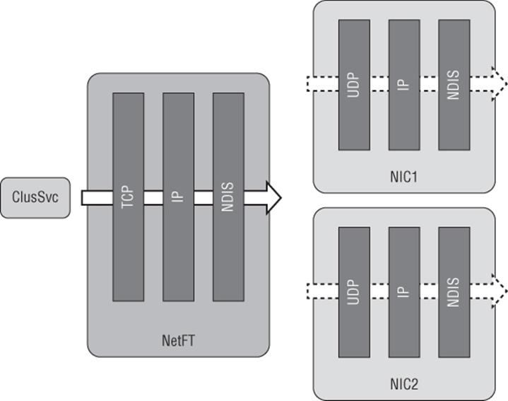
Figure 7.17 Cluster network properties
What is interesting here is that the cluster service traffic essentially flows through the networking stack twice, once through the NetFT bound stack and then through the stack bound to the network adapter being used. In Windows Server 2012, a new component was introduced, the NetFT Virtual Adapter Performance Filter that was automatically bound to physical network adapters. When it sees any cluster traffic on the physical network adapter, it sends it to the NetFT adapter directly, bypassing the redirection through the physical network stack. This sounds good, but if you also have a guest cluster running on virtual machines within the Hyper-V host cluster and guest VMs are running on different nodes in the cluster, the performance filter would grab not only the host cluster communications but also the guest cluster communications, which means the communication would never reach the virtual machines and therefore break clustering. To resolve this problem, the Microsoft Failover Cluster Virtual Adapter Performance Filter would need to be disabled in Windows Server 2012, which is why it's disabled by default in Windows Server 2012 R2.
There are no manual firewall configurations required when using clustering. When the Failover Clustering feature is installed, a number of built-in inbound and outbound rules are automatically enabled for the inbox Windows Firewall. If you are using a third-party firewall solution, however, it's important that you enable the required firewall exceptions. The best way to do this is look at all the Failover Cluster firewall exceptions and emulate them in whatever firewall product you are using.
Performing Cluster Validation
Now that you understand the importance of the cluster network and communications, it's time to actually get a cluster up and running, which is a simple process. The cluster validation process performs detailed tests of all the major areas related to the cluster configuration, such as network, storage, and OS tests and tests specific to Hyper-V to ensure that the cluster will be workable and supported by Microsoft.
As previously mentioned, the cluster validation should be performed prior to creating a cluster and anytime you make a major change to the cluster, such as adding a new node to the cluster, adding a new network or adding new types of storage. Additionally, the cluster validation tool is a useful tool to run if you are experiencing problems with the cluster; it allows specific groups of tests to be run instead of all tests.
Provided the failover clustering feature is installed on the cluster nodes to perform a validation, follow these steps:
1. Start Failover Cluster Manager.
2. The root Failover Cluster Manager navigation node will be selected, which in the Management section has a Validate Configuration action, as shown in Figure 7.18, that you should click. If you wish to validate an existing cluster, select the cluster in Failover Cluster Manager and then click its Validate Cluster action.
3. Click Next on the introduction screen of the Validate a Configuration Wizard.
4. If this is a validation for what will be a new cluster, you must add all the servers that will become members of the new cluster by entering their names or clicking Browse and selecting them. Remember that all members of a cluster must be part of the same domain. As each name is entered, a check will be performed on the node. Once all machines are added to the server list, click Next.
5. The tests to be performed can be selected. For a new cluster, you should always leave the default of Run All Tests selected. Even for a validation of an existing cluster, it's a good idea to run all tests. However, you can select the Run Only Tests I Select option to expose an additional configuration page that allows you to select the specific tests you wish to run (shown in Figure 7.19, which I've edited to show all the Hyper-V options in detail). If the Hyper-V role is not installed, then the Hyper-V tests are not run. Notice the level of depth the cluster tests perform on Hyper-V. Click Next.
6. If you selected to perform storage checks on an existing cluster, you can select which storage will be validated. Storage validation involves testing arbitration and moving tested storage units, which would shut down any roles using the storage, so do not test any storage running roles such as virtual machines. I like to have a small LUN that I don't use that I keep for storage validations. If this is a validation for what will be a new cluster, then you are not prompted for which storage to validate. Click Next.
7. A confirmation is shown of the tests that will be performed. Click Next to start the validation.
8. The validation can take some time, especially if there is a large amount of storage attached, but the progress of the test and its success/failure is shown (Figure 7.20).
9. Once the validation is complete, a summary is displayed. The success/failure of each test is shown and a View Report button can be clicked to see the report results in the web browser with the details of each test. If the validation is for servers not yet in a cluster, a check box is automatically selected, Create The Cluster Now Using The Validated Nodes, which means when Finish is clicked, the Create Cluster Wizard will launch with the servers automatically populated. Click Finish to exit the validation wizard.
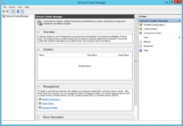
Figure 7.18 The empty Failover Cluster Manager interface
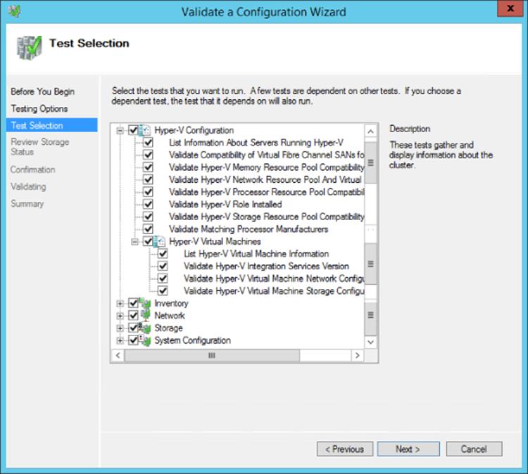
Figure 7.19 Cluster tests available
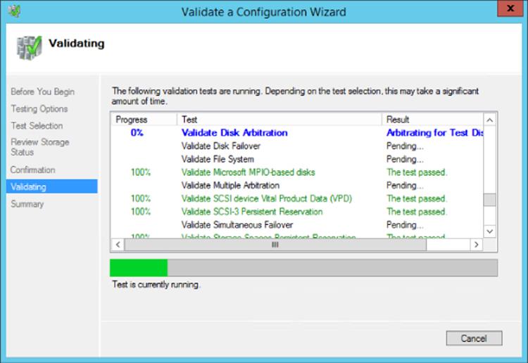
Figure 7.20 Cluster validation in progress
The validation reports are also saved to the folder C:\Windows\Cluster\Reports, which can be viewed at any time. The report name contains the date and time of execution. Open up a report and look; there is a huge amount of detail. These reports can be useful to keep as a record of the server configuration.
Validation can also be performed using PowerShell with the Test-Cluster cmdlet. This can be used to validate an existing cluster by passing a cluster name (or no cluster name and it will be performed on the local cluster) or used to validate nodes that will join a cluster by passing the server names of the future cluster members, as shown in these examples:
· Use Test-Cluster to validate the local cluster.
· Use Test-Cluster -Node node1,node2 to validate nodes node1 and node2 for a potential new cluster.
For more examples of Test-Cluster, view the Microsoft documentation at the following location:
http://technet.microsoft.com/en-us/library/ee461026.aspx
One useful tip is to select a specific disk for the purpose of storage testing. The disk can be passed using the -Disk parameter. For example, this just runs the storage test on a specific disk:
Test-Cluster -Cluster <cluster> -Disk "<disk, for example Cluster Disk 5>" ´
-Include Storage
Creating a Cluster
Once the validation process has been run, the next step is to create the cluster, which is actually very simple. At the end of the validation there was a check box option, Create The Cluster Now Using The Validated Nodes. Keep that selected, and when you click Finish it will launch the Create Cluster Wizard. If you did not select the Create Cluster option, simply run the Create Cluster action and the only additional step you will need to perform is to specify the servers that will be joining the cluster. The only information you need to create the cluster is a name for the cluster and an IP address if you don't wish to use DHCP. Perform the following steps to complete the cluster process:
1. Click Next on the introduction page of the Create Cluster Wizard.
2. Enter the NetBIOS name that will be used to manage/access the cluster. If DHCP is used for the network adapters in the cluster servers, DHCP will automatically be used. If DHCP is not used, an IP address should be configured. Click Next.
3. The confirmation screen will be displayed. Leave the Add All Eligible Storage To The Cluster box checked because this will automatically add all storage that is accessible to all nodes in the cluster and that supports being clustered. Click Next.
4. The cluster will be created and a summary displayed. When the report is visible, review it and click Finish.
A computer object would have been created in Active Directory automatically and named the same as the cluster name specified during cluster creation. By default it will be created in the Computers container.
Note that by default the create cluster process selected the smallest cluster disk that was 512 MB or greater and initialized and formatted for the disk witness, whether there was an even or odd number of nodes. If you wish to change the witness use the More Actions ⇒ Configure Cluster Quorum Settings and change it as previously described in this chapter.
Creating Clusters with SCVMM
SCVMM can also help with clustering your Hyper-V hosts (and with 2012 R2, your Scale-Out File Server clusters). SCVMM can be used to initially deploy Hyper-V hosts as part of a cluster or take existing Hyper-V hosts and join them to a cluster. To use SCVMM to create and manage the cluster, it's important that SCVMM also fully manages the storage it uses. There are other requirements for using SCVMM to create and manage clusters:
· The cluster should meet the normal cluster requirements (part of Active Directory domain, same OS, and configuration level) and pass validation.
· The domain of the Hyper-V hosts must be trusted by the domain of the SCVMM management server.
· The Hyper-V hosts must be in the same host group in SCVMM.
· Hyper-V hosts must be on the same IP subnet.
Microsoft has detailed documentation on the requirements at
http://technet.microsoft.com/en-us/library/gg610630.aspx
The actual cluster creation is a wizard-driven process that validates the requirements of the cluster, enables the failover cluster feature on the hosts if it's not already installed, ensures that all storage is correctly unmasked to the hosts (remember, SCVMM must be managing the storage that is presented to the cluster), and makes each disk a Cluster Shared Volume. Follow these steps to create a cluster:
1. Open the SCVMM console and open the Fabric workspace.
2. Select Servers in the navigation pane.
3. From the Home tab, select Create ⇒ Hyper-V Cluster.
4. Enter a name for the new cluster and select the Run As account to use to actually perform the configurations on each host. Click Next.
5. On the Nodes page, add the nodes that will be part of the cluster by selecting the servers and clicking the Add button. Then click Next.
6. If any of the nodes are using static IP configuration, you will be prompted for the IP configuration, which can be either an IP pool or a specific IP address to use. Enter the IP configuration and click Next.
7. Storage that can be clustered (that is, storage that is available to all the nodes) will be displayed. Select the storage to be used for the cluster, and then select the classification, partition style, file system, format instructions, and whether to make the disk a CSV. By default, a format is performed, so all data would be lost, although you can select Do Not Format in the File System area. Click Next.
8. Configure the virtual networks that will be available for all cluster nodes. Click Next.
9. On the Summary page, click Finish and the cluster will be created. Once the creation process is complete, the cluster will be shown in the Servers view of SCVMM.
Once the cluster is created, it can be fully managed with SCVMM, and there are some attributes you may want to customize. Right-click the cluster and selecting Properties. On the General page of the properties is a cluster reserve value that by default is set to 1. This defines the number of nodes in this cluster you want to be tolerant of failure. For example, a value of 1 means you want the cluster to be able to tolerate the failure of 1 node. This is used when deploying resources because SCVMM will ensure that the cluster is not overutilized so that it would not be able to run all deployed virtual machines in the event of a node failure. If you had a 4-node cluster and had the reserve set to 1, SCVMM would allow the deployment of only virtual machines that could be run on 3 nodes. If this was a lab environment where you just wanted to fill every node, then you could set the cluster reserve to 0. Alternatively, in a larger cluster, such as a 64-node cluster, you may want to increase the reserve value to 2 or 4 to support more nodes being unavailable. This value is important not just for node failures but also for maintenance where a node is drained of all virtual machines so it can be patched and rebooted. This means it's important in a production environment to always have the reserve set to at least 1 so that maintenance can be performed without having to shut down virtual machines.
The other tabs of the cluster properties show information about the status, storage, and networks. Figure 7.21 shows the view of the current shared volumes, giving easy insight into the utilization.
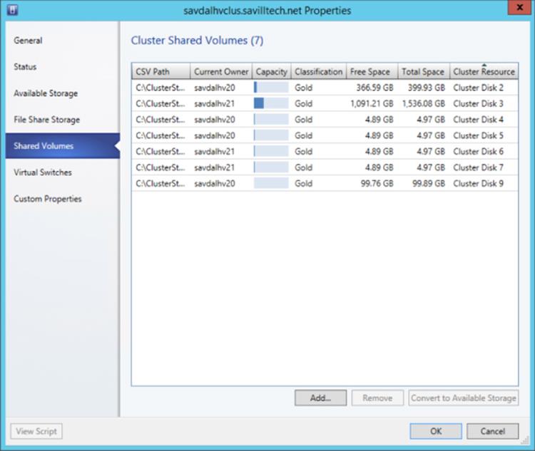
Figure 7.21 Shared volumes
Another nice feature for the cluster is the ability to view the networking details via the View Networking action, as shown in Figure 7.22. This shows the cluster, the nodes in the cluster, and the networks that are connected to from each node.
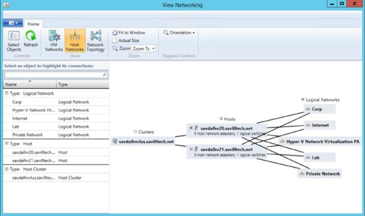
Figure 7.22 Viewing the networking available for a cluster
As with networking guidance, the best practice when using SCVMM to manage Hyper-V is to perform all actions from SCVMM, including creating clusters. If you do create clusters outside of SCVMM, then SCVMM will still detect them and allow them to be configured.
Using Cluster Shared Volumes
Traditionally, with a cluster that has shared storage (which means the storage is accessible to all nodes in the cluster), only one node in the cluster would actually mount a specific LUN that is NTFS formatted. The basic problem is that NTFS is a shared nothing file system. It does not support multiple operating system instances connecting concurrently to it, which is the limitation. More specifically metadata updates such as file open/close of extension operations cannot be performed by multiple operating system instances; the actual SAN holding the LUNs supports multiple concurrent connections with no problem.
One solution would have been to create a new cluster-aware file system that could be mounted on multiple nodes in the cluster at the same time, which would remove the LUN failover requirement. However, this would have been a huge undertaking both from a development perspective and from a testing perspective when you consider how many services, applications, and tools are based around features of NTFS.
With this in mind, Microsoft looked at ways to make NTFS-formatted LUNs available to multiple nodes in a cluster concurrently, enabling all the nodes to read and write at the same time, and came up with Cluster Shared Volumes (CSV). In Windows Server 2012, when you're viewing a CSV in Disk Manager, the file system type shows as CSVFS instead of NTFS. Under the covers, CSVFS is still NTFS, but the CSVFS adds its own mini file system, which is leveraged to enable many of the capabilities I will discuss in this section. For the most part, though, it just acts as a pass-through to NTFS (or ReFS in Windows Server 2012 R2).
Prior to Windows Server 2012, to use Cluster Shared Volumes, the feature had to be manually enabled. CSV is now available by default, and to make a cluster disk a CSV, you select the disk in the Storage ⇒ Disks view of Failover Cluster Manager and use the Add To Cluster Shared Volumes action, shown in Figure 7.23. This can also be performed using the Add-ClusterSharedVolume cmdlet and passing the clustered disk name, as in the following example:
Add-ClusterSharedVolume –Name "Cluster Disk 1"
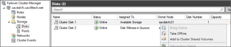
Figure 7.23 Making a cluster disk a CSV
When a disk is enabled for CSV, any previous mounts or drive letters are removed and the disk is made available as a child folder of the %systemroot%\ClusterStorage folder as Volume<n>—for example, C:\ClusterStorage\Volume1 for the first volume,C:\ClusterStorage\Volume2 for the next, and so on. The content of the disk will be visible as content within that disk's Volume folder. Place each virtual machine in its own folder as a best practice, as shown in Figure 7.24.
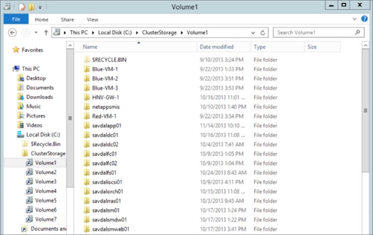
Figure 7.24 Viewing cluster shared volumes in Explorer
The ClusterStorage structure is shared, providing a single consistent filename space to all nodes in the cluster so every node has the same view. Once a disk is added to Cluster Shared Volumes, it is accessible to all nodes at the same time. All nodes can read and write concurrently to storage that is part of ClusterStorage.
Remember that the problem with NTFS being used concurrently by multiple operating system instances is related to metadata changes and the chance of corruptions if multiple operating systems make metadata changes at the same time. Cluster Shared Volumes fixes this by having one node assigned to act as the coordinator node for each specific CSV. This is the node that has the disk online locally and has complete access to the disk as a locally mounted device. All of the other nodes do not have the disk mounted but instead receive a raw sector map of the files of interest to them on each LUN that is part of CSV, which enables the non-coordinator nodes to perform read and write operations directly to the disk without actually mounting the NTFS volume. This is known as Direct IO.
The mechanism that allowed this Direct IO in Windows Server 2008 R2 was the CSV filter (CsvFlt) that was injected into the file system stack in all nodes in the cluster that received the sector map from the coordinator node of each CSV disk and then used that information to capture operations to the ClusterStorage namespace and perform the Direct IO as required. In Windows Server 2012, this changed to the CSVFS mini file system. The CSV technology allows the non-coordinator nodes to directly perform IO to the disk, which is the most common activity when dealing with virtual hard disks. However, no namespace/metadata changes can be made by non-coordinator nodes, such as, for example, creating, deleting, resizing, and opening files. These operations require management of the NTFS file system structure, which is carefully controlled by the coordinator node to avoid corruption. Fortunately these types of actions are relatively rare, and when a non-coordinator node needs to perform such an action, it forwards the action via SMB to the coordinator node that then makes the namespace changes on its behalf since the coordinator has the NTFS locally mounted and thus has full metadata access. This is shown in action in Figure 7.25, where a single node is acting coordinator for both disks.
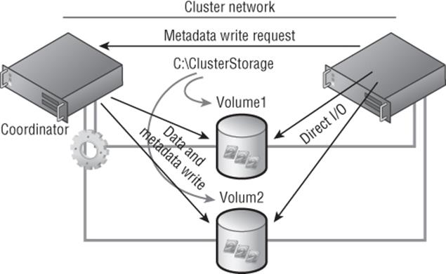
Figure 7.25 Cluster Shared Volume normal operation
The CSV technology actually provides another very useful feature. In the event a non-coordinator node loses direct access to the LUN—for example, its iSCSI network connection fails—all of its IO can be performed over SMB via the coordinator node using the cluster network. This is known as redirected IO and is shown in Figure 7.26.
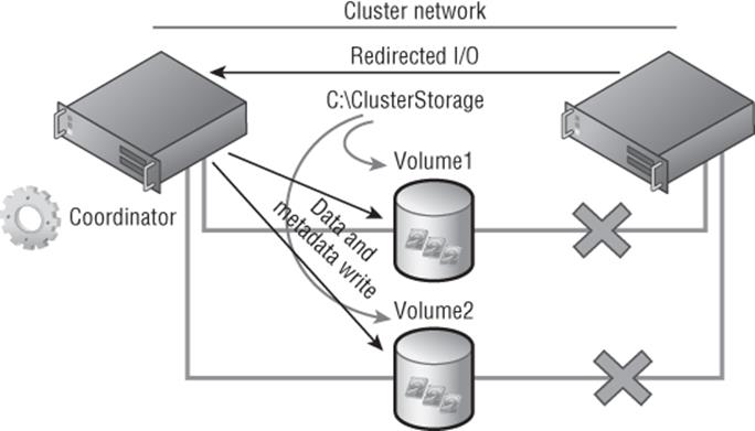
Figure 7.26 Cluster Shared Volume in redirected mode
The actual coordinator node can be changed with minimal impact. There is a slight pause in IO if you move the coordinator to another node because the IO is queued at each node, but the pause is unlikely to be noticed, which is critical given how important the coordinator node is to CSV. Windows Server 2012 R2 introduces an automatic rebalancing of coordinator roles for CSV volumes, which is why typically you will see each node in the cluster having an equal number of disks it is coordinator for.
There are some considerations when you have multiple nodes directly writing to blocks on the disk in some operations, such as disk maintenance like defragmentation or performing a backup. In Windows Server 2008 R2, manual actions were required before performing these maintenance-type actions in addition to ensuring that actions were taking on the coordinator node for the disk. Windows Server 2012 really optimized this process to automatically place the CSV in maintenance mode when required, and it also moves the coordinator of the CSV between nodes as required. In Windows Server 2012, the backup applications are all CSV aware to ensure proper actions, plus in Windows Server 2012 R2, VSS actually got more intelligent; it understands when the VSS snapshot is performed even when running on a non-coordinator node. The ChkDsk process was completely rewritten in Windows Server 2012 to reduce the amount of volume offline time for potentially hours to at most 8 seconds, and on CSV there is actually no offline time at all because of the additional redirection introduced by CSV. Behind the scenes, if ChkDsk needs to run against a CSV volume, the handles between the physical disk and CSV are released, but CSV maintains the handles applications have to CSV. This means once ChkDsk has completed, within a few seconds the handles are restored between the disk and CSV. CSV can then map the restored handles back to the original and persisted handles of the applications to CSV, which means no break in access, only a slight pause in I/O.
Cluster Shared Volumes in Windows Server 2008 R2 supported only Hyper-V virtual machine workloads. In Windows Server 2012, CSV was also supported for a special type of cluster file share, a scale-out file server, which leveraged CSV as the storage for a file share that could be shared by multiple nodes in the cluster simultaneously. This was targeted to provide SMB 3 services for enterprise workloads such as Hyper-V virtual machines running over SMB 3, but it also allowed SQL Server databases to run over SMB 3. Windows Server 2012 R2 further adds to CSV-supported workloads, including SQL Server databases, without connecting to storage via SMB 3.
With CSV, all nodes in the cluster can access the same storage at the same time. This makes moving virtual machines between nodes simple because no dismount/mount is required of LUNs, but it also means you can reduce the number of LUNs actually required in the environment since virtual machines can now run across different servers, even when stored on the same LUN.
Windows Server 2012 introduced some additional features to CSV, specifically around performance with CSV Cache. CSV uses unbuffered IO for read and write operations, which means no caching is ever used. Windows Server 2012 introduced the ability to use a portion of the system memory as a read cache for CSV on each node in the cluster, which improves read performance. There are two steps to enable CSV Cache in Windows Server 2012 and only one step to enable it in Windows Server 2012 R2.
First, the amount of memory that can be used by the host for CSV Cache must be configured. In the following examples, I set a value of 4 GB.
Windows Server 2012:
(Get-Cluster).SharedVolumeBlockCacheSizeInMB = 4096
Windows Server 2012 R2:
(Get-Cluster).BlockCacheSize = 4096
For Windows Server 2012, the CSV Cache must be enabled on a per-disk basis. For Windows Server 2012 R2, the CSV Cache is enabled by default. To enable a disk for CSV Cache with Windows Server 2012, use the following command:
Get-ClusterSharedVolume "Cluster Disk 1" | ´
Set-ClusterParameter CsvEnableBlockCache 1
The property is renamed EnableBlockCache in Windows Server 2012 R2 if you ever want to disable CSV Cache for a specific disk. No reboot is required when changing the CSV cache configuration.
In Windows Server 2012, the CSV Cache could be set to up to 20 percent of the system memory only. In Windows Server 2012 R2, it can be set to up to 80 percent of the system memory. The ability to set such a large cache is aimed at scale-out file servers, where committing more memory to cache will result in great performance gains. For Hyper-V clusters, typically it's better to have memory available to virtual machines, while some CSV cache will help overall performance.
Windows Server 2012 R2 adds support for ReFS with CSV. However, Hyper-V virtual machines are not supported on ReFS, which means you will still use NTFS to store your active virtual machines. Windows Server 2012 R2 also adds extended clustered storage space support, including support for storage spaces that use tiering, write-back cache, and parity. Data deduplication is also supported with CSV in Windows Server 2012 R2.
A nice addition in Windows Server 2012 R2 is increased diagnosibility for CSV. You can see the actual reason a CSV is in redirected mode, which previously was very hard to ascertain. Using the Get-ClusterSharedVolumeState PowerShell cmdlet will show the CSV state and the reason for the state. In the following example, all my CSVs are not redirected, but you can see where the reason for redirection would be displayed:
PS C:\> Get-ClusterSharedVolumeState
Name : Cluster Disk 2
VolumeName : \\?\Volume{2574685f-9cc6-4763-8d4b-b13af940d478}\
Node : savdalhv21
StateInfo : Direct
VolumeFriendlyName : Volume2
FileSystemRedirectedIOReason : NotFileSystemRedirected
BlockRedirectedIOReason : NotBlockRedirected
Name : Cluster Disk 2
VolumeName : \\?\Volume{2574685f-9cc6-4763-8d4b-b13af940d478}\
Node : savdalhv20
StateInfo : Direct
VolumeFriendlyName : Volume2
FileSystemRedirectedIOReason : NotFileSystemRedirected
BlockRedirectedIOReason : NotBlockRedirected
In a Hyper-V environment, I would recommend making every cluster disk used for storing virtual machines a CSV. There is no downside, and it enables the very efficient mobility of virtual machines and limits the number of LUNs required.
Making a Virtual Machine a Clustered Virtual Machine
To create a new clustered virtual machine using Failover Cluster Manager, select the Virtual Machines ⇒ New Virtual Machine action from the Roles navigation node, as shown in Figure 7.27. This will prompt for the node on which to initially create the virtual machine, and then the normal New Virtual Machine Wizard as seen in Hyper-V Manager will launch and allow all the attributes of the virtual machine to be specified.
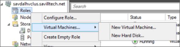
Figure 7.27 Creating a new clustered virtual machine using Failover Cluster Manager
If you have existing virtual machines that are hosted on cluster nodes but are not actually cluster resources, it is easy to make a virtual machine a clustered resource:
1. Within Failover Cluster Manager, select the Configure Role action from the Roles navigation node.
2. Click Next on the wizard introduction screen.
3. From the list of available role types, scroll down and select Virtual Machine and then click Next.
4. You'll see a list of all virtual machines that are running on the cluster hosts but are not clustered. Check the boxes for the virtual machines you wish to cluster, as shown in Figure 7.28, and click Next.
5. Click Next on the configuration screen.
6. Once complete, click Finish.
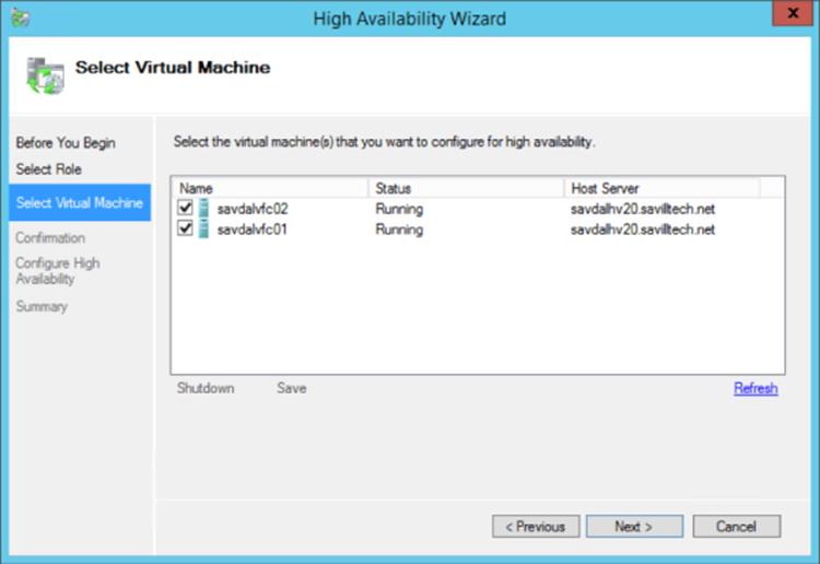
Figure 7.28 Selecting the virtual machines to be made clustered resources
If you have virtual machines that are cluster resources but you wish to make them nonclustered, select the resource in Failover Cluster Manager and select the Remove action. This has no impact on the availability of the virtual machine and does not require the virtual machine to be stopped.
To create a clustered virtual machine in SCVMM, the process is exactly the same as creating a regular virtual machine. There is only one change to the virtual machine configuration. On the Configure Hardware page of the Create Virtual Machine Wizard, look at the Advanced options and select the Availability section. Check the Make This Virtual Machine Highly Available box, as shown in Figure 7.29. This will tell SCVMM to deploy this virtual machine to a cluster and make the virtual machine highly available.
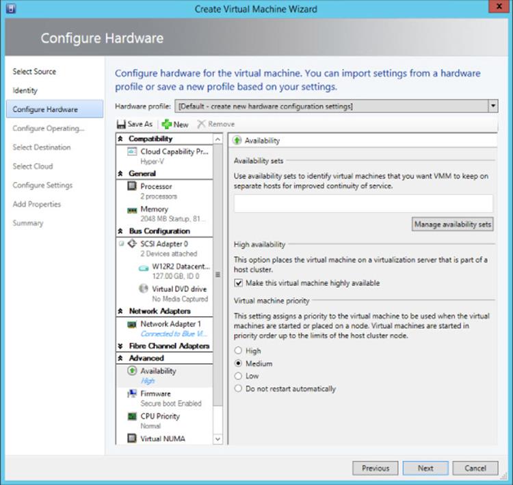
Figure 7.29 Setting the high availability option for a virtual machine
Once a virtual machine is clustered, a priority for the virtual machine can be configured via the virtual machine's properties within Failover Cluster Manager. The property can be set to Low, Medium, or High and is used when virtual machines need to be started, ensuring that the high-priority virtual machines start first and so on. This is also used where there are not enough resources to start all virtual machines and lower-priority virtual machines can be stopped to allow higher-priority virtual machines to start.
Live Migration
Live Migration is the Hyper-V technology that enables a virtual machine to be moved between Hyper-V hosts. In Windows Server 2008 R2, Live Migration provided the functionality to migrate the memory and state of a virtual machine between hosts in a cluster while the virtual machine was still running. The storage of the virtual machine was available to both hosts in the cluster simultaneously through the use of Cluster Shared Volumes.
There are really six key stages to the original Live Migration process in Windows Server 2008 R2, and they remain today when using shared storage:
· A Live Migration connection is made between the source and target Hyper-V hosts.
· The virtual machine configuration and device information is transferred and a container virtual machine is created on the target Hyper-V host.
· The memory of the virtual machine is transferred.
· The source virtual machine is suspended and the state and remaining memory pages are transferred.
· The virtual machine is resumed on the target Hyper-V host.
· A reverse ARP is sent over the network to enable network traffic to find the virtual machine on the new host.
The transfer of the memory is the most interesting aspect of Live Migration. It's not possible to just copy the memory of a virtual machine to another node because as the memory is being copied, the VM is still running, which means parts of the memory being copied are changing, and although the copy is from memory to memory over very fast networks, it still takes a finite amount of time, and pausing the VM while the memory is copied would be an outage. The solution is to take an iterative approach that does not result in a perceived period of unavailability by any clients of the virtual machine and ensures that any TCP/IP connections do not timeout.
An initial transfer of the VM memory is performed, which involves the bulk of the information and the bulk of the time taken during a Live Migration. Remember that the virtual machine is still running and so we need a way to track pages of memory that change while we are copying. To this end, the worker process on the current node creates a “dirty bitmap” of memory pages used by the virtual machine and registers for modify notifications on the pages of memory used by the VM. When a memory page is modified, the bitmap of memory is updated to show that a page has been modified. Once the first pass of the memory copy is complete, all the pages of memory that have been marked dirty in the memory map are recopied to the target. This time only the changed pages are copied, which means there will be far fewer pages to copy and the operation should be much faster. Once again, though, while we are copying these pages, other memory pages may change and so this memory copy process repeats itself.
In an ideal world, with each iteration of memory copy, the amount of data to copy will shrink as the time to copy decreases and we reach a point where all the memory has been copied and we can perform a switch. However, this may not always be the case, which is why there is a limit to the number of memory copy passes that are performed; otherwise, the memory copy may just repeat forever.
Once the memory pages have all been copied or we have reached our maximum number of copy passes (five with Windows Server 2012 R2), it comes time to switch the virtual machine to execute on the target node. To make this switch, the virtual machine is suspended on the source node, and any final memory pages that could not be copied as part of the memory transfer phase are transferred along with the state of the VM to the target; this state of the VM that is transferred includes items such as device and processor state. The virtual machine is then resumed on the target node and an unsolicited ARP reply is sent, notifying that the IP address used by the VM has moved to a new location, which enables routing devices to update their tables. It is at this moment that clients connect to the target node. Yes, there is a slight suspend of the VM, which is required to copy the state information, but this suspend is milliseconds and below the TCP connection time-out threshold, which is the goal because clients will not disconnect during the Live Migration process and users are unlikely to notice anything. Once the migration to the new target is complete, a message is sent to the previous host notifying it that it can clean up the VM environment. This whole process is shown in Figure 7.30 to help clarify the sequence of steps.
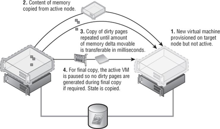
Figure 7.30 The complete Live Migration process
A Live Migration operation uses a large amount of network bandwidth, which meant in the 2008 R2 time frame a dedicated 1 Gbps network was advised for Live Migration. That then changed in the 2012 time frame to leverage converged networking and to use QoS to ensure that Live Migration received sufficient bandwidth.
When I talked about cluster networks, I mentioned that there was a metric used for the cluster networks to determine the prioritization of the networks to be used for cluster communications and the cluster network would use the lowest-cost network. The same prioritization is used for Live Migration, but to avoid conflicting with cluster traffic, Live Migration will automatically select the second-least-cost network. If you have a wish to use the same network for Live Migration as for cluster communications, you can override this using the graphical interface and using PowerShell.
In Windows Server 2008 R2, the network used for Live Migration was set on the virtual machine group properties via the Network For Live Migration tab. I have a write-up on the 2008 R2 method at the following location:
http://windowsitpro.com/windows/q-which-network-does-live-migration-traffic-use
This was changed in Windows Server 2012 to be a property of the cluster networks for the cluster. This can be set as follows:
1. Launch Failover Cluster Manager.
2. Right-click Networks and select Live Migration Settings.
3. A list of all cluster networks will be displayed. Check the networks that should be used for Live Migration and move them up and down to set their priority. As shown in Figure 7.31, I used the cluster network, which is a 10 Gbps network, and I leveraged QoS to ensure that Live Migration gets sufficient bandwidth. Click OK.
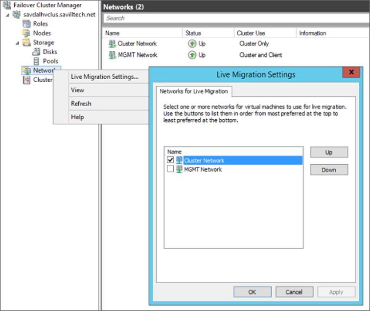
Figure 7.31 Setting the Live Migration network for a cluster
The Live Migration network can be changed using PowerShell, but it's the configuration to actually specify the name of the networks that should not be used for Live Migration. Therefore, if you have a specific network to be used for Live Migration, it should be placed in the following PowerShell command (in the example, my Live Migration network is named Migration Network):
Get-ClusterResourceType -Name "Virtual Machine" | Set-ClusterParameter ´
-Name MigrationExcludeNetworks -Value ([String]::Join(";",(Get-ClusterNetwork ´
| Where-Object {$_.Name -ne "Migration Network"}).ID))
In Windows Server 2008 R2, only one concurrent Live Migration could be performed between any two nodes in a cluster. For example, a Live Migration could be performed between node A and node B and a separate Live Migration could be performed between node C and node D, but it would not be possible to have two Live Migrations between A and B, nor would it be possible to have a Live Migration between node A and node B and between node A and node C. Failover Cluster Manager would also not allow the queuing of Live Migrations (although SCVMM did). The logic was that a single Live Migration would saturate a 1 Gbps network link and most datacenters were 1 Gbps. This has changed in Windows Server 2012 to allow multiple concurrent Live Migrations between hosts up to the limit you specify as part of the Live Migration configuration, which I will cover later in this chapter. Windows Server 2012 Failover Cluster Manager also introduces the concept of queuing Live Migrations that can not be actioned immediately.
In Windows Server 2012 and Windows Server 2012 R2 failover clusters, the Live Migration process remains the same. Virtual machines are always created on shared storage. However, instead of the virtual machines having to be stored on cluster storage, they can be stored on an SMB 3 file share that has been configured so each node in the cluster and the cluster account have full permissions. Note that if you are storing virtual machines in a cluster on a SMB 3 file share, it's important that the file share is not a single point of failure; it should be a scale-out file server, which itself is actually using Cluster Shared Volumes for the share storage. This also allows the use of Shared VHDX.
Windows Server 2012 Live Migration Enhancements
One of the key reasons that Live Migration was restricted to within a cluster in Windows Server 2008 R2 was that the storage between the source and the target must be available, which meant Cluster Shared Volumes had to be used. Windows Server 2012 introduces the ability to use a SMB file share to store virtual machines, enabling hosts outside of a cluster to view the same storage provided they had the right permissions. This enabled a new type of Live Migration in Windows Server 2012, where SMB is leveraged to store the virtual machine and then the Live Migration technology is leveraged to move the virtual machine state and memory before the handle of the virtual machine's resources on the SMB share switches to the target node.
In a cluster environment, the network used for Live Migration is configured as part of the cluster network configuration. For nonclustered hosts, Live Migration must be configured and enabled if it was not enabled when you enabled the Hyper-V role on the server. The configuration for Live Migration is part of the Hyper-V host's core configuration, which is as follows:
1. Launch Hyper-V Manager (this can also be configured using SCVMM in the Migration Settings area of the server's properties).
2. Select the Hyper-V host, and select the Hyper-V Settings action.
3. Select the Live Migrations area.
4. Check the Enable Incoming And Outgoing Live Migrations check box, as shown in Figure 7.32.
5. Note that the number of simultaneous Live Migrations allowed can be configured, and this number is the maximum allowed and not necessarily the number of simultaneous Live Migrations that will always be performed. The migration module examines the amount of available bandwidth and dynamically ascertains if an additional Live Migration could be supported by the amount of bandwidth available on the migration network. If not, the migration is queued.
6. The configuration allows any network that is available to be used for Live Migration. Or you can select a specific network or networks by checking Use These IP Addresses For Live Migration and then adding and ordering IP networks that should be used in CIDR notation—for example, xxx.xxx.xxx.xxx/n, where the n is the number of bits to use for the subnet mask, so 10.1.2.0/24 is the same as 10.1.2.0 with a subnet mask of 255.255.255.0. This would allow any IP address in the 10.1.2.0 network to be used for Live Migration.
To set this using PowerShell use the Add-VMMigrationNetwork and Set-VMMigrationNetwork cmdlets. Note that this setting is for the networks that can be used to receive incoming Live Migration. When a host is the source of a Live Migration, it will use whatever network it has available that can communicate with the Live Migration network configured to receive on the Live Migration target.
7. Click OK.
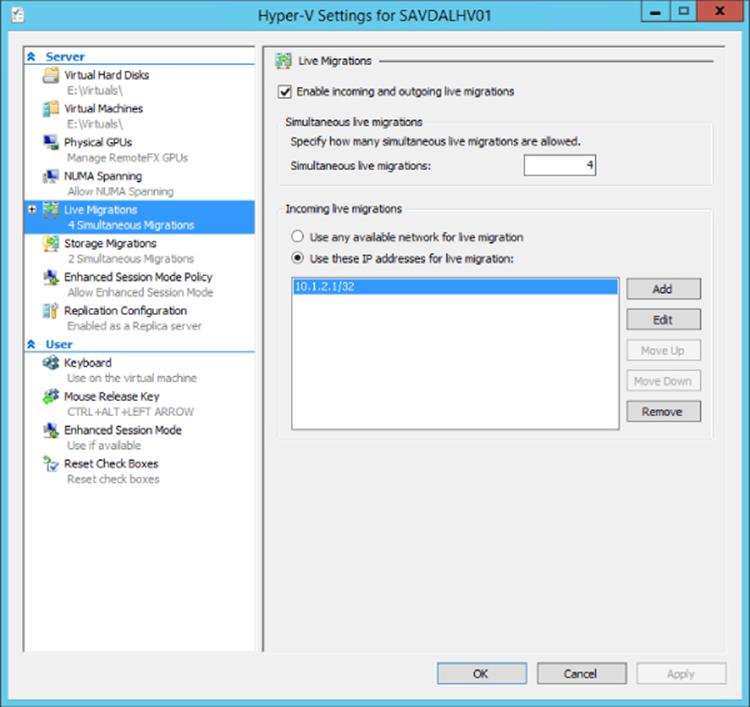
Figure 7.32 Enabling Live Migration for a stand-alone Hyper-V host
By default, CredSSP is used for the security between the source and target Hyper-V host, but there is another configuration option, known as constrained delegation, which I will cover later.
Live Storage Move
Windows Server 2012 introduced the ability to move the storage of a virtual machine without having to shut down the virtual machine first, sometimes call Live Storage Move or Storage Migration.
Windows Server 2012 supports three main types of storage for virtual machines: direct attached; SAN based, such as storage connected via Fibre Channel or iSCSI; and new to Windows Server 2012 is support for SMB 3.0 file shares such as those hosted on a Windows Server 2012 file server or any NAS/SAN that has SMB 3.0 support. Windows Server 2012 Storage Migration allows the storage used by a virtual machine, which includes its configuration and virtual hard disks, to be moved between any supported storage with zero downtime to the virtual machine. This could be migration just to a different folder on the same disk, between LUNs on the same SAN, from direct attached to a SAN, from a SAN to a SMB file share—it doesn't matter. If the storage is supported by Hyper-V, then virtual machines can be moved with no downtime. It should be noted that storage migration cannot move nonvirtualized storage, which means if a virtual machine is using pass-through storage, that cannot be moved. The good news is with the new VHDX format that allows 64 TB virtual disks, there really is no reason to use pass-through storage anymore from a size or performance perspective. It is also not possible to perform a storage migration for a Shared VHDX.
The ability to move the storage of a virtual machine at any time without impacting the availability of the virtual machine is vital in two key scenarios:
· The organization acquires some new storage, such as a new SAN, or is migrating to a new SMB 3.0–based appliance and needs to move virtual machines with no downtime as part of a planned migration effort.
· The storage in the environment was not planned out as well as hoped and now either it's run out of space or it can't keep up with the IOPS requirements and virtual machines need to be moved as a matter of urgency. In my experience, this is the most common scenario, but it is important to realize that performing a storage migration puts a large additional load on the storage because every block has to be read and written to. Therefore, if you are having a storage performance problem, the problem will be worse during a storage migration.
The mechanics behind the Windows Server 2012 storage migration are actually quite simple, but they provide the most optimal migration process. Remember that the virtual machine is not moving between hosts; it's only the storage moving from a source location to a target location.
Storage migration uses a one-pass copy of virtual hard drives that works as follows:
1. The storage migration is initiated from the GUI or PowerShell.
2. The copy of the source virtual hard disks, smart paging file, snapshots, and configuration files to the target location is initiated.
3. At the same time as the copy initiates, all writes are performed on the source and target virtual hard disks through a mirroring process in the virtual storage stack.
4. Once the copy of the virtual hard disks is complete, the virtual machine is switched to use the virtual hard disks on the target location (the target is up-to-date because all writes have been mirrored to it while the copy was in progress).
5. The virtual hard disks and configuration files are deleted from the source.
The storage migration process is managed by the VMMS process in the parent partition, but the heavy lifting of the actual storage migration is performed by the virtual machine's worker process and the storage virtualization service provider (VSP) in the parent partition. The mechanism for the copy of the storage is just a regular, unbuffered copy operation plus the additional IO on the target for the mirroring of writes occurring during the copy. However, in reality the additional IO for the ongoing writes is negligible compared to the main unbuffered file copy. The path used is whatever path exists to the target, which means if it's SAN, it will use iSCSI/Fibre Channel, and if it's SMB, it will use whichever network adapter or network adapters have a path to the share. Any underlying storage technologies that optimize performance are fully utilized. This means if you are copying over SMB (from or to) and you are using NIC Teaming, SMB direct, or SMB Multichannel, then those technologies will be used. If you are using a SAN and that SAN supports offloaded data transfer (ODX) and a virtual machine is being moved within a single LUN or between LUNs, ODX will be utilized, which will mean the move uses almost no load on the host and will complete very quickly.
The SAN ODX scenario is the best case, and for all the other cases, it is important to realize exactly what an unbuffered copy means to your system. The unbuffered copy is used because during the storage migration it would not be desirable on a virtualization host to use a large amount of system memory for caching of data. When a copy is performed, it can cause a significant amount of IO load on your system for both the reading of the source and writing to the target. To get an idea, try a manual unbuffered copy on your system using the xcopy command with the /J switch (which sets the copy to unbuffered). That is similar to the load a storage migration would inflict on your system (once again considering the ongoing mirrored writes as fairly negligible). Consider, therefore, moving a virtual machine between folders on a local disk, likely a worst-case scenario. The data would be read from and written to the same disk, causing a huge amount of disk thrashing. It would likely take a long time and would adversely affect any other virtual machines that use that disk. That is a worst-case scenario though. If the source and target were different storage devices, the additional load would not be as severe as a local move but would still need to be considered.
There is nothing Hyper-V specific about the disk IO caused by moving a VM. It would be the same for any data migration technology (except that other technologies may not have capabilities like ODX if a SAN is involved); ultimately the data has to be read and has to be written. This does not mean you should not use storage migration, but it does mean you should plan carefully when you use it. It's not something you would likely want to perform during normal working hours because of the possible adverse effect to other loads, and I suspect that's why at this time there is no automated storage migration process as part of the Dynamic Optimization in System Center Virtual Machine Manager that rebalances virtual machines within a cluster. If you detected a large IO load on a storage subsystem in the middle of the day, the last thing you would want to do is add a huge extra load on it by trying to move things around. The best option is to track IO over time and then at a quiet time move the virtual machines' storage, which would be easy to script with PowerShell or automate with technologies like System Center Orchestrator.
There is no specific configuration to enable storage migration. As previously stated, storage migration uses whatever path exists to communicate with the source and target storage and is enabled by default (in fact, you can't disable it). The only actual configuration is setting how many simultaneous storage migrations are allowed, and this is configured via the Hyper-V Settings action in the Storage Migrations area.
This can also be configured using PowerShell:
Set-VMHost -MaximumStorageMigrations <number to allow>
There is only one scenario where some extra configuration is required and that is if you are using SMB storage for the target of a storage migration and are initiating the migration remotely, either through Hyper-V Manager or PowerShell; that is, you are not running the tools on the actual Hyper-V host, which is the preferred management approach for Windows Server 2012 because all management should be done remotely using PowerShell or from a Windows 8/8/1 machine. When you configure SMB storage for use with Hyper-V, there are a number of specific permissions you set, including giving the administrators full control as the person creating a VM on SMB or moving to SMB as part of a storage migration as their credential are used. To enable the credential to be used on a remote SMB file server, constrained delegation must be used, which I mentioned earlier related to Live Migrations in nonclustered environments. I will cover constrained delegation in detail later.
Storage migrations can be triggered through Hyper-V Manager or through PowerShell, and there are two different options when performing a storage migration. Move everything to a single location or select different locations for each item stored as part of a virtual machine, that is, one location for the configuration file, one for the snapshots, one for smart paging, one for virtual hard disk 1, one for virtual hard disk 2, and so on, as shown in Figure 7.33.
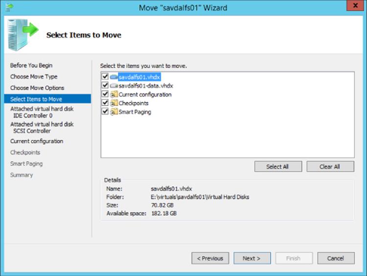
Figure 7.33 The different storage objects for a virtual machine
Start with performing the move using Hyper-V Manager, which will help you understand the options that are possible:
1. Launch Hyper-V Manager.
2. Select the virtual machine whose storage needs to be moved and select the Move action.
3. Click Next on the Before You Begin page of the wizard.
4. Since we are moving only the storage, select the Move The Virtual Machine's Storage option.
5. You can now choose to move all the virtual machine's data to a single location, which is the default, or you can select to move the virtual machine's data to a different location or move only the virtual hard disks for the virtual machine but none of its other data. Make your selection and click Next.
6. If you selected the default to move everything to a single location, you will be prompted for the new storage location. Just click next. If you selected either of the other two options, you will have a separate page to select the target location for each element of the virtual machine's data, so set the location for each item and click Next.
7. Review your options and click Finish to initiate the storage migration.
To perform the storage migration from PowerShell, the Move-VMStorage cmdlet is used. If you're moving everything to a single location, it's very easy; you just pass the virtual machine name and the new target location with the DestinationStoragePath parameter (note that a subfolder with the VM name is not created automatically, so if you want the VM in its own subfolder, you need to specify that as part of the target path), as in this example:
Move-VMStorage -DestinationStoragePath <target path> -VMName <vmname>
If, however, you want to move the parts to different locations, it's more complicated. Instead of DestinationStoragePath, the SmartPagingFilePath, SnapshotFilePath, and VirtualMachinePath parameters are used to pass the location for the smart paging file, snapshots, and virtual machine configuration, respectively, but this still leaves the virtual hard disks. For the VHDs, the Vhds parameter is used. You could have more than one VHD for a single virtual machine (in fact you could have hundreds), and PowerShell does not really like an arbitrary number of parameters, so to pass the virtual hard disk's new location, you actually have to create a hash value for the SourceFilePath and DestinationFilePath for each virtual hard disk and then place those into an array that is passed to the –Vhds parameter. Pleasant!
In the following example, a virtual machine is being moved with three hard disks and its smart paging file, configuration, and snapshots. You don't have to move all elements of a virtual machine; you only need to specify the pieces you wish to move. Other elements not specified would just stay in their current location. Note that in the following command, squiggly brackets {} are used for the hash values (value pairs) while regular brackets () are used for the array.
Move-VMStorage -VMName <vmname> -SmartPagingFilePath d<smart paging file path> ´
-SnapshotFilePath <snapshot path> -VirtualMachinePath <vm configuration path> ´
-Vhds @(@{ "SourceFilePath " = "C:\vm\vhd1.vhdx "; ´
"DestinationFilePath " = "D:\VHDs\vhd1.vhdx "},´
@{ "SourceFilePath " = "C:\vm\vhd2.vhdx ";´
"DestinationFilePath " = "E:\VHDs\vhd2..vhdx "}, ´
@{ "SourceFilePath " = "C:\vm\vhd3.vhdx ";´
"DestinationFilePath " = "F:\VHDs\vhd3.vhdx "})
Once the storage migration is initiated, it will run until its finished; it will never give up no matter how long it may take. As the administrator, you can cancel the storage migration manually through the Cancel move Storage action, or if you rebooted the Hyper-V host, this would also cause all storage migrations to be cancelled. The progress of storage migrations can be seen in the Hyper-V Manager tool or they can be queried through WMI, as shown here:
PS C:\ > Get-WmiObject -Namespace root\virtualization\v2 -Class Msvm_MigrationJob |´
ft Name, JobStatus, PercentComplete, VirtualSystemName
Name JobStatus PercentComplete VirtualSystemName
---- --------- --------------- -----------------
Moving Storage Job is running 14 6A7C0DEF-9805-…
Shared Nothing Live Migration
With the existing Live Migration technology and the new ability to move the storage of a virtual machine with no downtime, Windows Server 2012 introduced Shared Nothing Live Migration, which allows you to move virtual machines between any two Windows Server 2012 Hyper-V hosts with no downtime and no shared resource. This means no shared storage, no shared cluster membership; all that is needed is a gigabit network connection between the Windows Server 2012 Hyper-V hosts. With this network connection, a virtual machine can be moved between Hyper-V hosts, which includes moving the virtual machine's virtual hard disks, the virtual machine's memory content, and then the processor and device state with no downtime to the virtual machine. Do not think that the Shared Nothing Live Migration capability means Failover Clustering is no longer needed. Failover Clustering provides a high availability solution, while Shared Nothing Live Migration is a mobility solution but does give new flexibility in the planned movement of virtual machines between all Hyper-V hosts in your environment without downtime. It can supplement Failover Cluster usage. Think of now being able to move virtual machines into a cluster, out of a cluster, and between clusters with no downtime to the virtual machine in addition to moving them between stand-alone hosts. Any storage dependencies are removed with Shared Nothing Live Migration.
There is some assurance that the hosts in a failover cluster have a similar configuration, providing a confident migration of virtual machines between hosts without the fear of misconfigurations and therefore problems with virtual machines functioning if migrated. When Shared Nothing Live Migration is used to migrate virtual machines between unclustered Hyper-V hosts, there is no guarantee of common configuration, and therefore you need to ensure that the requirements for Shared Nothing Live Migration are met:
· At a minimum, there must be two Windows Server 2012 installations with the Hyper-V role enabled or the free Microsoft Hyper-V Server 2012 OS.
· Each server must have access to its own location to store virtual machines, which could be local storage, SAN attached, or an SMB share.
· Servers must have the same type of processor or at least the same family of processor (i.e., Intel or AMD) if the Processor Compatibility feature of the virtual machine is used.
· Servers must be part of the same Active Directory domain.
· Hosts must be connected by at least a 1 Gbps connection (although a separate private network for the Live Migration traffic is recommended but not necessary), which the two servers can communicate over. The network adapter used must have both the Client for Microsoft Networks and File and Printer Sharing for Microsoft Networks enabled because these services are used for any storage migrations.
· Each Hyper-V server should have the same virtual switches defined with the same name to avoid errors and manual steps when performing the migration. If a virtual switch has the same name as that used by a virtual machine being migrated, an error will be displayed and the administrator performing the migration will need to select which switch on the target Hyper-V server the VM's network adapter should connect to.
· Virtual machines being migrated must not use pass-through storage or shared VHDX (with Windows Server 2012 R2).
Earlier, in the section “Windows Server 2012 Live Migration Enhancements,” I described how to enable and configure Live Migration in the scenario of using Live Migration when using SMB as the storage. It is the same for Shared Nothing Live Migration; there is no additional configuration required.
To perform a Shared Nothing Live Migration, select the Move action for a virtual machine, and for the move type, select the Move The Virtual Machine option, type the name of the destination Hyper-V server, and finally choose how the virtual machine should be moved. For a Shared Nothing Live Migration, you need to select one of the first two options available: move the virtual machine's data to a single location or move the virtual machine's data by selecting where to move the items. The first option allows you to specify a single location where you want to store the virtual machine's configuration, hard disks, and snapshots on the target. The second option allows you to select a specific location for each of the virtual machine's items in addition to selecting which items should be moved. Make your choice and select the folder on the destination server. The move operation will start and will take a varying amount of time based on the size of the virtual hard disks and memory to move and also the rate of change. The move will be completed without any downtime or loss of connectivity to the virtual machine. This can be seen in a video at the following location:
www.savilltech.com/videos/sharednothinglivemigration/sharednothinglivemigration.wmv
The move can also be initiated using the Move-VM PowerShell cmdlet.
In my experience, the Shared Nothing Live Migration can be one of the most troublesome migrations to get working, so here are my top troubleshooting tips:
· First, make sure you have adhered to the requirements I listed previously.
· Check the Event Viewer for detailed messages. The location to check is Applications and Services Logs > Microsoft > Windows > Hyper-V-VMMW > Admin.
· Make sure the IP configuration is correct between the source and target. The servers must be able to communicate. Try pinging the target Live Migration IP address from the source server.
· Run the following PowerShell command in an elevated session to show the IP addresses being used for a server and the order in which they will be used:
·gwmi -n root\virtualization\v2 Msvm_VirtualSystemMigrationService |´
select MigrationServiceListenerIPAddressList
· Make sure the Hyper-V (MIG-TCP-In) firewall exception is enabled on the target.
· The target server must be resolvable by DNS. Try an nslookup of the target server. On the target server, run the command ipconfig /registerdns and then run ipconfig /flushdns on the source server.
· On the source server, flush the Address Resolution Protocol (ARP) cache with the command arp -d *.
· To test connectivity, try a remote WMI command to the target (the Windows Management Instrumentation (WMI-In) firewall exception must be enabled on the target), such as the following:
gwmi -computer <DestinationComputerName> -n root\virtualization\v2 Msvm_VirtualSystemMigrationService
· Try changing the IP address used for Live Migration; for example, if you're currently using 10.1.2.0/24, try changing to the specific IP address (e.g., 10.1.2.1/32). Also check any IPsec configurations or firewalls between the sources and target. Check for multiple NICs on the same subnet that could be causing problems, and if you find any, try disabling one of them.
· Try setting authentication to CredSSP and initiate locally from a Hyper-V server. If this works, the problem is the Kerberos delegation.
The most common problems I have seen are a misconfiguration of Kerberos and the IP configuration, but failing to resolve the target server via DNS will also cause problems.
Configuring Constrained Delegation
Performing a Live Migration within a cluster removed the need for any special security considerations when moving virtual machines because the cluster account was used throughout migration operations. However, with Shared Nothing Live Migration, Live Migration using SMB, and the ability to move storage to SMB shares introduce some additional security, specifically credential considerations.
Outside of a cluster, each Hyper-V host has its own computer account without a shared credential, and when operations are performed, the user account of the user performing the action is normally used. With a Live Migration, actions are being taken on the source and target Hyper-V servers (and also file servers if the VM is stored on an SMB share, but more on that later), which both require that the actions be authenticated. If the administrator performing the Live Migration is logged onto the source or the target Hyper-V server and initiates Shared Nothing Live Migration using the local Hyper-V Manager, then the administrator's credentials can be used both locally and to run commands on the other Hyper-V server. In this scenario, CredSSP works fine and allows the user's credentials to be used on the remote server from the client, basically a single authentication hop from the local machine of the user performing the action (which happens to be one of the Hyper-V servers) to a remote server.
Remember, however, the whole goal for Windows Server 2012 and management in general: remote management and automation. Having to actually log on to the source or target Hyper-V server every time a Live Migration outside of a cluster is required is a huge inconvenience for remote management. If a user was logged on to their local computer running Hyper-V Manager and tried to initiate a Live Migration between Hyper-V host A and B, it would fail. The user's credential would be used on Hyper-V host A (which is one hop from the client machine to Hyper-V host A) but Hyper-V host A would not be able to use that credential on Host B to complete the Live Migration because CredSSP does not allow a credential to be passed on to another system (more than one hop).
This is where the option to use Kerberos enables full remote management. Kerberos supports constrained delegation of authentication, which means when a user on their local machine performs an action on a remote server, that remote server can use that user's credentials for authentication on another remote server. This initially seems to be a troubling concept, that a server I remotely connect to can just take my credentials and use them on another server, potentially without my knowing. The constrained part of constrained delegation comes into play and requires some setup before Kerberos can be used as the authentication protocol for Live Migration. To avoid exactly the problem I just described, where a server could use a remote user's credentials on another server, delegation has to be configured for each computer account that is allowed to perform actions on another server on behalf of another user. This delegation is configured using the Active Directory Users and Computer management tool and the computer account properties of the server that will be allowed to delegate. Additionally, when leveraging SMB file shares for Shared Nothing Live Migration or part of a storage migration, constrained delegation must be configured for the cifs service to each SMB file server. Follow these steps:
1. Launch Active Directory Users and Computers.
2. Navigate to your Hyper-V servers, right-click on one, and select Properties.
3. Select the Delegation tab.
4. Make sure Trust This Computer For Delegation To Specified Services Only is selected and that Use Kerberos Only is selected.
5. Click Add.
6. Click Users or Computers and select your other Hyper-V servers or SMB file servers. Click OK.
7. In the list of available services, select Microsoft Virtual System Migration Service or cifs for each server, depending on if it's a Hyper-V host (Microsoft Virtual System Migration Service) or SMB file server (cifs). Click OK.
8. Repeat the steps for all the Hyper-V hosts or SMB file shares it will communicate with that need constrained delegation as shown in Figure 7.34.
9. Repeat the whole process for each other Hyper-V so every Hyper-V host has constrained delegation configured to the other Hyper-V hosts and SMB file shares.
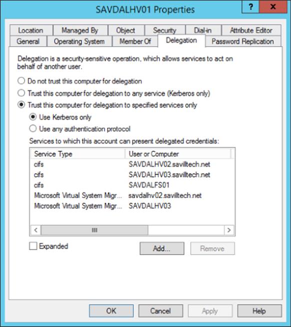
Figure 7.34 The different storage objects for a virtual machine
You must set authentication to Use Kerberos Only. It will not work if you select Use Any Authentication Protocol. It also won't work if you use the Trust This Computer For Delegation To Any Service (Kerberos Only) option. In my example configuration, I have a number of Hyper-V hosts, and in Figure 7.34, the configuration for savdalhv01 is shown. It has been configured for constrained delegation to the Hyper-V hosts savdalhv02 and savldalhv03 for cifs and migration in addition to the file server savdalfs01 for cifs only. I would repeat this configuration on savdalhv02 and savdalhv03 computer accounts, allowing delegation to the other hosts. The reason I have cifs enabled in addition to Microsoft Virtual System Migration Service for each Hyper-V host is in case virtual machines are using SMB storage that is being migrated, in which case cifs is required.
Once the Kerberos delegation is configured, the Live Migration will be able to be initiated from any remote Hyper-V Manager instance between trusted hosts. Remember also that all hosts that are participating in the Live Migration must have the same authentication configuration. While there is more work involved in the use of Kerberos authentication, the additional flexibility makes the additional work worthwhile and definitely recommended. To configure the authentication type to use from PowerShell, use the Set-VMHostcmdlet and set VirtualMachineMigrationAuthenticationType to either CredSSP or Kerberos.
Initiating Simultaneous Migrations Using PowerShell
The Move-VM PowerShell cmdlet can be used to trigger Live Migrations, and to trigger multiple Live Migrations, the following can be used:
Get-VM blank1,blank2,blank3 | Move-VM -DestinationHost savdalhv02
The problem is this would live migrate blank1, and once that is finished, it would live migrate blank2, then blank3, and so on. It is not performing a simultaneous Live Migration, which is possible in Windows Server 2012.
One solution is to use the -parallel option available in PowerShell v3 workflows to trigger the Live Migrations to occur in parallel, as in this example:
Workflow Invoke-ParallelLiveMigrate
{
$VMLIST = get-vm blank1,blank2,blank3
ForEach -Parallel ($VM in $VMLIST)
{
Move-VM -Name $VM.Name -DestinationHost savdalhv02
}
}
Invoke-ParallelLiveMigrate
The Live Migrations will now occur in parallel. Make sure your Hyper-V hosts are configured with the needed setting for the number of concurrent Live Migrations you wish to perform on both the source and destination Hyper-V hosts.
Windows Server 2012 R2 Live Migration Enhancements
Windows Server 2012 R2 introduced performance improvements to Live Migration by allowing the memory transferred between hosts to be compressed or sent using SMB. The option to use compression means less network bandwidth and therefore faster Live Migrations, but additional processor resources are used to compress and decompress the memory. The option to use SMB is targeted to environments that have network adapters that support Remote Direct Memory Access (RDMA), which gives the fastest possible transfer of data with almost no server resource usage (compression is not used; it's not needed). By selecting SMB when network adapters support RDMA, you leverage the SMB Direct capability, which gives the best possible performance. Do not select SMB if your network adapters do not support RDMA.
By default, the compression option is selected for Live Migration, but it can be changed as follows:
1. Launch Hyper-V Manager (this can also be configured using SCVMM using the Migration Settings area of the server's properties).
2. Select the Hyper-V host and select the Hyper-V Settings action.
3. Select the Live Migrations area.
4. Click the plus sign next to Live Migrations to enable access to the Advanced Features configuration area.
5. Select the desired Performance Options setting, as shown in Figure 7.35. Notice also that the authentication protocol (CredSSP or Kerberos) is also selected in this area.
6. Click OK.
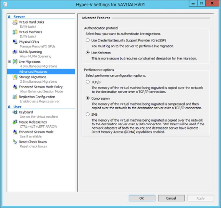
Figure 7.35 Setting the advanced configurations for Live Migration
Windows Server 2012 R2 also enables cross-version Live Migration. This allows a Live Migration from Windows Server 2012 to Windows Server 2012 R2 (but not the other way). This Live Migration enables an upgrade from Windows Server 2012 to Windows Server 2012 R2 Hyper-V hosts without requiring any downtime of the virtual machines.
Dynamic Optimization and Resource Balancing
When a virtual machine is created with SCVMM to a cluster, each node is given a star rating based upon its suitability to host the new virtual machine, and one of the criteria is the host's current utilization. Over time as new virtual machines are created, your cluster may become uneven with some hosts running many more virtual machines than others.
Dynamic Optimization (DO) is a new feature in SCVMM 2012 that is designed to ensure that the hosts within a cluster (Hyper-V, ESX, or XenServer) are spreading the virtual machine load as evenly as possible, avoiding certain hosts being heavily loaded (potentially affecting the performance of virtual machines) while other hosts are fairly lightly loaded. Dynamic Optimization is one of the most used features in almost all virtualized environments because of the dynamic balancing of virtual machines and because it removes a lot of the manual activities required of administrators around the placement of virtual machines. It is important to note that no amount of dynamic balancing can compensate for a poorly architected or overloaded environment, and it's still critical to perform accurate discovery and design of virtual environments.
DO is not considered a replacement for Performance Resource Optimization (PRO), which was present in SCVMM 2008 and leveraged System Center Operations Manager for detail on utilization of the environment. Instead, DO is considered a complementary technology that does not rely on Operations Manager and is seen very much as a reactive technology. DO works by periodically looking at the resource utilization of each host in a cluster, and if the utilization drops below defined levels, a rebalancing is performed of the virtual machines to better equalize host utilization throughout the cluster. As Figure 7.36 shows, thresholds for CPU, memory, disk, and network can be defined in addition to how aggressive the rebalancing will be. The more aggressive it is, the quicker DO will be to move virtual machines for even a small gain in performance, which means more Live Migrations.
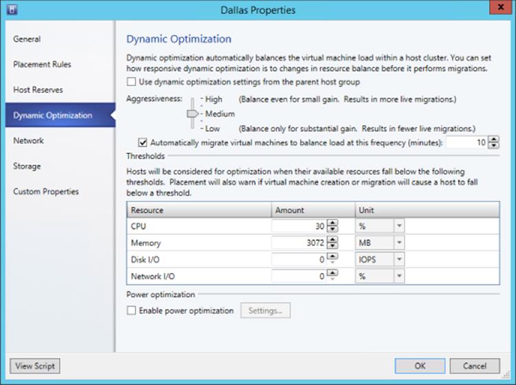
Figure 7.36 Dynamic Optimization options for a host group
While any host group can have the DO configurations set, the optimizations will be applied only to hosts that are in a cluster, plus that cluster must support zero downtime VM migrations such as Live Migration on Hyper-V, XenMotion, and vMotion on ESX. A manual DO can be initiated at any time by selecting a host cluster and running the Optimize Hosts action, which will display a list of recommended migrations. The great part is that this manual DO can be used even if DO is not configured on the actual host group, allowing one-off optimizations to be performed.
PRO is still present in SCVMM 2012. It leverages Operations Manager and is used as a more long-term placement technology, and it's also the only extensible placement technology. Third-party PRO packs can be installed to extend the placement logic.
Also in Figure 7.36 is an option to enable Power Optimization (PO, but I'm not going to refer to it as that). While Dynamic Optimization tries to spread load across all the hosts in a cluster evenly, Power Optimization aims to condense the number of hosts that need to be running in a cluster to run the virtual machine workload without negatively affecting the performance of the virtual machines and powering down those not required. Consider a typical IT infrastructure that during the workday is busy servicing employees and customers but during non-work hours is fairly idle. Power Optimization allows thresholds to be set to ensure that VMs can be consolidated and evacuated hosts can be powered down, provided the remaining running hosts don't have any CPU, memory, disk, or network resource drop below the configured thresholds.
This is similar to the configuration options we set for DO, but this time it's controlling how much consolidation can occur. Your Power Optimization thresholds should be set higher than those for Dynamic Optimization because the goal of Power Optimization is to consolidate in quiet times and if the Power Optimization thresholds were lower than the Dynamic Optimization thresholds, then hosts would be powered off and lots of Live Migrations would occur. VMs would be moved around and the hosts that were just powered off would be powered on again. The Power Optimization thresholds also need to be generous, leaving plenty of spare resource because resource utilization fluctuates even in quiet times and eventually it will pick up again during busy times. It will take time to power on and boot the servers that were powered down during Power Optimization times, so plenty of buffer capability is required to ensure no resource shortage.
Additionally, as Figure 7.37 shows, you can set the times Power Optimization can occur. In this example, I don't want Power Optimization to occur during business hours except for a few exceptions, however there is no reason to stop Power Optimization during working hours providing you set well-defined thresholds to ensure that hosts have sufficient spare resources and won't suddenly be overtaxed during the time it takes to power back on servers that were powered down.
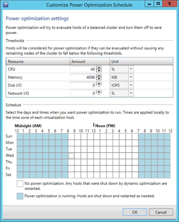
Figure 7.37 Power Optimization options for a host group
Waking servers is actually important because we don't want to power down servers that are not needed at a certain time and then be unable to start them up when they are needed again. A powered-down host is started using the host's Baseboard Management Controller (BMC), which needs to be configured on a per-host basis, and if the BMC is not present in a host or not configured, the host will not be able to be powered off as part of the Power Optimization process.
In partnership with the SCVMM placement logic and the Dynamic Optimization is the ability to create placement rules that can guide where virtual machines are placed. SCVMM contains 10 custom properties named Custom1 through Custom10. You can also create additional custom properties for the various types of SCVMM objects, such as a virtual machine (VM), a virtual machine template, hosts, host groups, clouds, and more.
You might create a custom property to store information, such as a VM's cost center, primary application function, desired physical location, or a contact email address—anything you can think of. These properties can then be used for administrators and business users to more easily understand information about assets in SCVMM and for reporting. The real power is realized when your custom properties are combined with custom placement rules that can utilize the custom properties to help control where VMs are placed.
For example, consider the scenario in which each business unit group has its own set of hosts. You could create a cost center property for VMs and hosts and then create a custom placement rule that says the cost center of the VM must match that of the host for placement.
These rules are used both for initial placement and as part of Dynamic Optimization. It's important to note when you create your custom placement rules that you have options if the rule should, must, or not match. Should means the placement will try to match but doesn't have to and if placement violates the rule, a warning is generated. If must is used, then placement isn't possible if the rule is violated. To create a custom property, use the following procedure:
1. Start the Virtual Machine Manager console.
2. Navigate to the VMs And Services workspace, select the VM you want to set a custom property for, and open its properties.
3. Select the Custom Properties area, and click the Manage Custom Properties button.
4. In the Manage Custom Properties dialog, click the Create button.
5. Enter a name and description for the custom property and click OK.
6. The new custom property will be available in the list of available properties. Select it and click the Add button so it becomes an assigned property, then click OK. Note that the View Script button is available to show Windows PowerShell script to perform the action you just performed in the GUI, such as, for example:
7. New-SCCustomProperty -Name "Cost Center" ´
-Description "Cost Center of the object" -AddMember @("VM")
8. You can now set a value for the custom property, and again the View Script button will show you the PowerShell script to perform the action.
9. Now select the properties of a host group, select the Custom Properties area, and click Manage Custom Properties. The custom property you already created is available. Add it to the assigned properties and enter a value.
10.In the same host group properties dialog is the Placement Rules page, which allows you to select custom properties. It also shows you how the custom property must/should relate to the host, as shown in Figure 7.38.
11.Click OK to all dialogs.
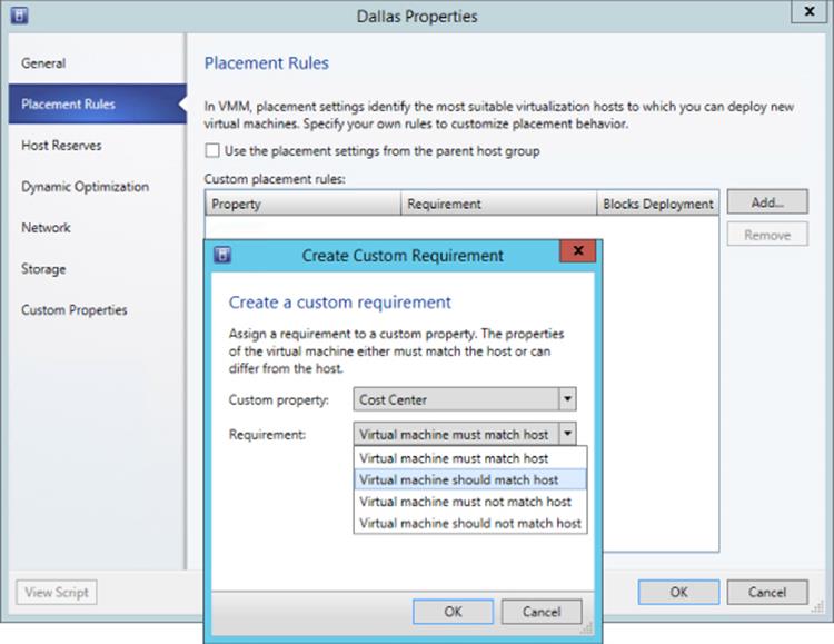
Figure 7.38 Setting a placement rule for a host group
The Bottom Line
1. Understand the quorum model used in Windows Server 2012 R12. Windows Server 2012 R2 removes all the previous different models that were based on how votes were allocated and the type of quorum resource. In Windows Server 2012 R2, each node has a vote and a witness is always configured, but it's only used when required. Windows Server 2012 introduced dynamic quorum, which helps ensure that clusters stay running for as long as possible as nodes' votes are removed from quorum because the nodes are unavailable. Windows Server 2012 R2 added dynamic witness to change the vote of the witness resource based on if there are an odd or even number of nodes in the cluster.
2. Identify the types of mobility available with Hyper-V.
Mobility focuses on the ability to move virtual machines between Hyper-V hosts. Virtual machines within a cluster can be live migrated between any node very efficiently since all nodes have access to the same storage, allowing only the memory and state to be copied between the nodes. Windows Server 2012 introduced the ability to move the storage of a virtual machine with no downtime, which when combined with Live Migration enables a Shared Nothing Live Migration capability that means a virtual machine can be moved between any two Hyper-V hosts without the need for shared storage or a cluster, with no downtime to the virtual machine.
Shared Nothing Live Migration does not remove the need for failover clustering but provides the maximum flexibility possible, enabling virtual machines to be moved between stand-alone hosts, between clusters, and between stand-alone hosts and clusters.
1. Master It Why is constrained delegation needed when using Shared Nothing Live Migration with remote management?
3. Understand the best way to patch a cluster with minimal impact to workloads. All virtual machines in a cluster can run on any of the member nodes. That means before you patch and reboot a node, all virtual machines should be moved to other nodes using Live Migration, which removes any impact on the availability of the virtual machines. While the migration of virtual machines between nodes can be performed manually, Windows Server 2012 failover clustering provides Cluster Aware Updating, giving you a single-click ability to patch the entire cluster without any impact to virtual machines' availability. For pre–Windows Server 2012 clusters, SCVMM 2012 also provides an automated patching capability.
All materials on the site are licensed Creative Commons Attribution-Sharealike 3.0 Unported CC BY-SA 3.0 & GNU Free Documentation License (GFDL)
If you are the copyright holder of any material contained on our site and intend to remove it, please contact our site administrator for approval.
© 2016-2026 All site design rights belong to S.Y.A.