Windows Internals, Sixth Edition, Part 1 (2012)
Chapter 4. Management Mechanisms
This chapter describes four fundamental mechanisms in the Microsoft Windows operating system that are critical to its management and configuration:
§ The registry
§ Services
§ Unified Background Process Manager
§ Windows Management Instrumentation
§ Windows Diagnostics Infrastructure
The Registry
The registry plays a key role in the configuration and control of Windows systems. It is the repository for both systemwide and per-user settings. Although most people think of the registry as static data stored on the hard disk, as you’ll see in this section, the registry is also a window into various in-memory structures maintained by the Windows executive and kernel.
We’ll start by providing you with an overview of the registry structure, a discussion of the data types it supports, and a brief tour of the key information Windows maintains in the registry. Then we’ll look inside the internals of the configuration manager, the executive component responsible for implementing the registry database. Among the topics we’ll cover are the internal on-disk structure of the registry, how Windows retrieves configuration information when an application requests it, and what measures are employed to protect this critical system database.
Viewing and Changing the Registry
In general, you should never have to edit the registry directly: application and system settings stored in the registry that might require manual changes should have a corresponding user interface to control their modification. However, as you’ve already seen a number of times in this book, some advanced and debug settings have no editing user interface. Therefore, both graphical user interface (GUI) and command-line tools are included with Windows to enable you to view and modify the registry.
Windows comes with one main GUI tool for editing the registry—Regedit.exe—and a number of command-line registry tools. Reg.exe, for instance, has the ability to import, export, back up, and restore keys, as well as to compare, modify, and delete keys and values. It can also set or query flags used in UAC virtualization. Regini.exe, on the other hand, allows you to import registry data based on text files that contain ASCII or Unicode configuration data.
The Windows Driver Kit (WDK) also supplies a redistributable component, Offreg.dll, which hosts the Offline Registry Library. This library allows loading registry hive files in their binary format and applying operations on the files themselves, bypassing the usual logical loading and mapping that Windows requires for registry operations. Its use is primarily to assist in offline registry access, such as for purposes of integrity checking and validation. It can also provide performance benefits if the underlying data is not meant to be visible by the system, because the access is done through local file I/O instead of registry system calls.
Registry Usage
There are four principal times at which configuration data is read:
§ During the initial boot process, the boot loader reads configuration data and the list of boot device drivers to load into memory before initializing the kernel. Because the Boot Configuration Database (BCD) is really stored in a registry hive, one could argue that registry access happens even earlier, when the Boot Manager displays the list of operating systems.
§ During the kernel boot process, the kernel reads settings that specify which device drivers to load and how various system elements—such as the memory manager and process manager—configure themselves and tune system behavior.
§ During logon, Explorer and other Windows components read per-user preferences from the registry, including network drive-letter mappings, desktop wallpaper, screen saver, menu behavior, icon placement, and perhaps most importantly, which startup programs to launch and which files were most recently accessed.
§ During their startup, applications read systemwide settings, such as a list of optionally installed components and licensing data, as well as per-user settings that might include menu and toolbar placement and a list of most-recently accessed documents.
However, the registry can be read at other times as well, such as in response to a modification of a registry value or key. Although the registry provides asynchronous callbacks that are the preferred way to receive change notifications, some applications constantly monitor their configuration settings in the registry through polling and automatically take updated settings into account. In general, however, on an idle system there should be no registry activity and such applications violate best practices. (Process Monitor, from Sysinternals, is a great tool for tracking down such activity and the application or applications at fault.)
The registry is commonly modified in the following cases:
§ Although not a modification, the registry’s initial structure and many default settings are defined by a prototype version of the registry that ships on the Windows setup media that is copied onto a new installation.
§ Application setup utilities create default application settings and settings that reflect installation configuration choices.
§ During the installation of a device driver, the Plug and Play system creates settings in the registry that tell the I/O manager how to start the driver and creates other settings that configure the driver’s operation. (See Chapter 8, “I/O System,” in Part 2 for more information on how device drivers are installed.)
§ When you change application or system settings through user interfaces, the changes are often stored in the registry.
Registry Data Types
The registry is a database whose structure is similar to that of a disk volume. The registry contains keys, which are similar to a disk’s directories, and values, which are comparable to files on a disk. A key is a container that can consist of other keys (subkeys) or values. Values, on the other hand, store data. Top-level keys are root keys. Throughout this section, we’ll use the words subkey and key interchangeably.
Both keys and values borrow their naming convention from the file system. Thus, you can uniquely identify a value with the name mark, which is stored in a key called trade, with the name trade\mark. One exception to this naming scheme is each key’s unnamed value. Regedit displays the unnamed value as (Default).
Values store different kinds of data and can be one of the 12 types listed in Table 4-1. The majority of registry values are REG_DWORD, REG_BINARY, or REG_SZ. Values of type REG_DWORD can store numbers or Booleans (on/off values); REG_BINARY values can store numbers larger than 32 bits or raw data such as encrypted passwords; REG_SZ values store strings (Unicode, of course) that can represent elements such as names, file names, paths, and types.
Table 4-1. Registry Value Types
|
Value Type |
Description |
|
REG_NONE |
No value type |
|
REG_SZ |
Fixed-length Unicode string |
|
REG_EXPAND_SZ |
Variable-length Unicode string that can have embedded environment variables |
|
REG_BINARY |
Arbitrary-length binary data |
|
REG_DWORD |
32-bit number |
|
REG_DWORD_BIG_ENDIAN |
32-bit number, with high byte first |
|
REG_LINK |
Unicode symbolic link |
|
REG_MULTI_SZ |
Array of Unicode NULL-terminated strings |
|
REG_RESOURCE_LIST |
Hardware resource description |
|
REG_FULL_RESOURCE_DESCRIPTOR |
Hardware resource description |
|
REG_RESOURCE_REQUIREMENTS_LIST |
Resource requirements |
|
REG_QWORD |
64-bit number |
The REG_LINK type is particularly interesting because it lets a key transparently point to another key. When you traverse the registry through a link, the path searching continues at the target of the link. For example, if \Root1\Link has a REG_LINK value of \Root2\RegKey and RegKey contains the value RegValue, two paths identify RegValue: \Root1\Link\RegValue and \Root2\RegKey\RegValue. As explained in the next section, Windows prominently uses registry links: three of the six registry root keys are links to subkeys within the three nonlink root keys.
Registry Logical Structure
You can chart the organization of the registry via the data stored within it. There are six root keys (and you can’t add new root keys or delete existing ones) that store information, as shown in Table 4-2.
Table 4-2. The Six Root Keys
|
Root Key |
Description |
|
HKEY_CURRENT_USER |
Stores data associated with the currently logged-on user |
|
HKEY_USERS |
Stores information about all the accounts on the machine |
|
HKEY_CLASSES_ROOT |
Stores file association and Component Object Model (COM) object registration information |
|
HKEY_LOCAL_MACHINE |
Stores system-related information |
|
HKEY_PERFORMANCE_DATA |
Stores performance information |
|
HKEY_CURRENT_CONFIG |
Stores some information about the current hardware profile |
Why do root-key names begin with an H? Because the root-key names represent Windows handles (H) to keys (KEY). As mentioned in Chapter 1, HKLM is an abbreviation used for HKEY_LOCAL_MACHINE. Table 4-3 lists all the root keys and their abbreviations. The following sections explain in detail the contents and purpose of each of these six root keys.
Table 4-3. Registry Root Keys
|
Root Key |
Abbreviation |
Description |
Link |
|
HKEY_CURRENT_USER |
HKCU |
Points to the user profile of the currently logged-on user |
Subkey under HKEY_USERS corresponding to currently logged-on user |
|
HKEY_USERS |
HKU |
Contains subkeys for all loaded user profiles |
Not a link |
|
HKEY_CLASSES_ROOT |
HKCR |
Contains file association and COM registration information |
Not a direct link; rather, a merged view of HKLM\SOFTWARE\Classes and HKEY_USERS\<SID>\SOFTWARE\Classes |
|
HKEY_LOCAL_MACHINE |
HKLM |
Global settings for the machine. |
Not a link |
|
HKEY_CURRENT_CONFIG |
HKCC |
Current hardware profile |
HKLM\SYSTEM\CurrentControlSet\Hardware Profiles\Current |
|
HKEY_PERFORMANCE_DATA |
HKPD |
Performance counters |
Not a link |
HKEY_CURRENT_USER
The HKCU root key contains data regarding the preferences and software configuration of the locally logged-on user. It points to the currently logged-on user’s user profile, located on the hard disk at \Users\<username>\Ntuser.dat. (See the section Registry Internals later in this chapter to find out how root keys are mapped to files on the hard disk.) Whenever a user profile is loaded (such as at logon time or when a service process runs under the context of a specific user name), HKCU is created to map to the user’s key under HKEY_USERS. Table 4-4 lists some of the subkeys under HKCU.
Table 4-4. HKEY_CURRENT_USER Subkeys
|
Subkey |
Description |
|
AppEvents |
Sound/event associations |
|
Console |
Command window settings (for example, width, height, and colors) |
|
Control Panel |
Screen saver, desktop scheme, keyboard, and mouse settings, as well as accessibility and regional settings |
|
Environment |
Environment variable definitions |
|
EUDC |
Information on end-user defined characters |
|
Identities |
Windows Mail account information |
|
Keyboard Layout |
Keyboard layout setting (for example, U.S. or U.K.) |
|
Network |
Network drive mappings and settings |
|
Printers |
Printer connection settings |
|
Software |
User-specific software preferences |
|
Volatile Environment |
Volatile environment variable definitions |
HKEY_USERS
HKU contains a subkey for each loaded user profile and user class registration database on the system. It also contains a subkey named HKU\.DEFAULT that is linked to the profile for the system (which is used by processes running under the local system account and is described in more detail in the section Services later in this chapter). This is the profile used by Winlogon, for example, so that changes to the desktop background settings in that profile will be implemented on the logon screen. When a user logs on to a system for the first time and her account does not depend on a roaming domain profile (that is, the user’s profile is obtained from a central network location at the direction of a domain controller), the system creates a profile for her account that’s based on the profile stored in %SystemDrive%\Users\Default.
The location under which the system stores profiles is defined by the registry value HKLM\Software\Microsoft\Windows NT\CurrentVersion\ProfileList\ProfilesDirectory, which is by default set to %SystemDrive%\Users. The ProfileList key also stores the list of profiles present on a system. Information for each profile resides under a subkey that has a name reflecting the security identifier (SID) of the account to which the profile corresponds. (See Chapter 6, for more information on SIDs.) Data stored in a profile’s key includes the time of the last load of the profile in the ProfileLoadTimeLow value, the binary representation of the account SID in the Sid value, and the path to the profile’s on-disk hive (which is described later in this chapter in the Hives section) in the ProfileImagePath directory. Windows shows the list of profiles stored on a system in the User Profiles management dialog box, shown in Figure 4-1, which you access by clicking Settings in the User Profiles section of the Advanced tab in the Advanced System Settings of the System Control Panel applet.
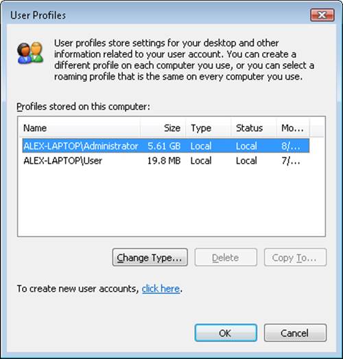
Figure 4-1. The User Profiles management dialog box
EXPERIMENT: WATCHING PROFILE LOADING AND UNLOADING
You can see a profile load into the registry and then unload by using the Runas command to launch a process in an account that’s not currently logged on to the machine. While the new process is running, run Regedit and note the loaded profile key under HKEY_USERS. After terminating the process, perform a refresh in Regedit by pressing the F5 key and the profile should no longer be present.
HKEY_CLASSES_ROOT
HKCR consists of three types of information: file extension associations, COM class registrations, and the virtualized registry root for User Account Control (UAC). (See Chapter 6 for more information on UAC.) A key exists for every registered file name extension. Most keys contain a REG_SZ value that points to another key in HKCR containing the association information for the class of files that extension represents.
For example, HKCR\.xls would point to information on Microsoft Office Excel files in a key such as HKCU\.xls\Excel.Sheet.8. Other keys contain configuration details for COM objects registered on the system. The UAC virtualized registry is located in the VirtualStore key, which is not related to the other kinds of data stored in HKCR.
The data under HKEY_CLASSES_ROOT comes from two sources:
§ The per-user class registration data in HKCU\SOFTWARE\Classes (mapped to the file on hard disk \Users\<username>\AppData\Local\Microsoft\Windows\Usrclass.dat)
§ Systemwide class registration data in HKLM\SOFTWARE\Classes
The reason that there is a separation of per-user registration data from systemwide registration data is so that roaming profiles can contain these customizations. It also closes a security hole: a nonprivileged user cannot change or delete keys in the systemwide version HKEY_CLASSES_ROOT, and thus cannot affect the operation of applications on the system. Nonprivileged users and applications can read systemwide data and can add new keys and values to systemwide data (which are mirrored in their per-user data), but they can modify existing keys and values in their private data only.
HKEY_LOCAL_MACHINE
HKLM is the root key that contains all the systemwide configuration subkeys: BCD00000000, COMPONENTS (loaded dynamically as needed), HARDWARE, SAM, SECURITY, SOFTWARE, and SYSTEM.
The HKLM\BCD00000000 subkey contains the Boot Configuration Database (BCD) information loaded as a registry hive. This database replaces the Boot.ini file that was used before Windows Vista and adds greater flexibility and isolation of per-installation boot configuration data. (For more information on the BCD, see Chapter 13, “Startup and Shutdown,” in Part 2.)
Each entry in the BCD, such as a Windows installation or the command-line settings for the installation, is stored in the Objects subkey, either as an object referenced by a GUID (in the case of a boot entry) or as a numeric subkey called an element. Most of these raw elements are documented in the BCD reference in the MSDN Library and define various command-line settings or boot parameters. The value associated with each element subkey corresponds to the value for its respective command-line flag or boot parameter.
The BCDEdit command-line utility allows you to modify the BCD using symbolic names for the elements and objects. It also provides extensive help for all the boot options available; unfortunately, it works only locally. Because the registry can be opened remotely as well as imported from a hive file, you can modify or read the BCD of a remote computer by using the Registry Editor. The following experiment shows you how to enable kernel debugging by using the Registry Editor.
EXPERIMENT: OFFLINE OR REMOTE BCD EDITING
In this experiment, you enable debugging through editing the BCD inside the registry. For the purposes of this example, you edit the local copy of the BCD, but the point of this technique is that it can be used on any machine’s BCD hive. Follow these steps to add the /DEBUG command-line flag:
1. Open the Registry Editor, and then navigate to the HKLM\BCD00000000 key. Expand every subkey so that the numerical identifiers of each Elements key are fully visible.
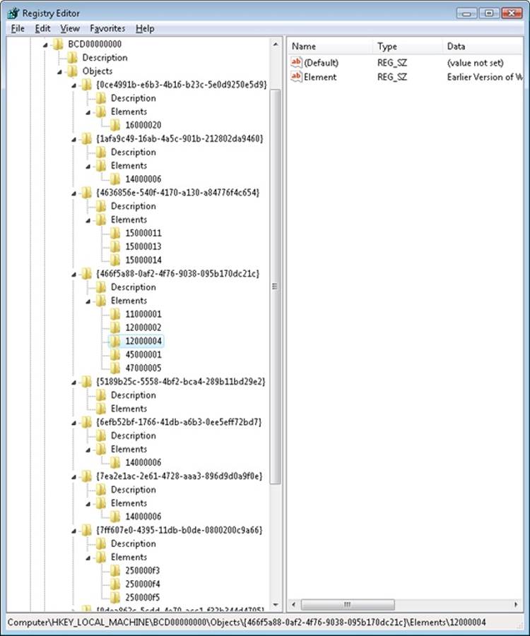
2. Identify the boot entry for your Windows installation by locating the Description with a Type value of 0x10200003, and then check ID 0x12000004 in the Elements tree. In the Element value of that subkey, you should find the name of your version of Windows, such as Windows 7. If you have more than one Windows installation on your machine, you may need to check the 0x22000002 Element, which contains the path, such as \Windows.
3. Now that you’ve found the correct GUID for your Windows installation, create a new subkey under the Elements subkey for that GUID and name it 0x260000a0. If this subkey already exists, simply navigate to it.
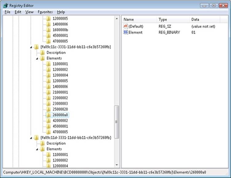
4. If you had to create the subkey, now create a binary value called Element inside it.
5. Edit the value and set it to 01. This will enable kernel-mode debugging. Here’s what these changes should look like:
NOTE
The 0x12000004 ID corresponds to BcdLibraryString_ApplicationPath, while the 0x22000002 ID corresponds to BcdOSLoaderString_SystemRoot. Finally, the ID you added, 0x260000a0, corresponds to BcdOSLoaderBoolean_KernelDebuggerEnabled. These values are documented in the BCD reference in the MSDN Library.
The HKLM\COMPONENTS subkey contains information pertinent to the Component Based Servicing (CBS) stack. This stack contains various files and resources that are part of a Windows installation image (used by the Automated Installation Kit or the OEM Preinstallation Kit) or an active installation. The CBS APIs that exist for servicing purposes use the information located in this key to identify installed components and their configuration information. This information is used whenever components are installed, updated, or removed either individually (called units) or in groups (called packages). To optimize system resources, because this key can get quite large, it is only dynamically loaded and unloaded as needed if the CBS stack is servicing a request.
The HKLM\HARDWARE subkey maintains descriptions of the system’s legacy hardware and some hardware device-to-driver mappings. On a modern system, only a few peripherals—such as keyboard, mouse, and ACPI BIOS data—are likely to be found here. The Device Manager tool (which is available by running System from Control Panel and then clicking Device Manager) lets you view registry hardware information that it obtains by simply reading values out of the HARDWARE key (although it primarily uses the HKLM\SYSTEM\CurrentControlSet\Enum tree).
HKLM\SAM holds local account and group information, such as user passwords, group definitions, and domain associations. Windows Server systems that are operating as domain controllers store domain accounts and groups in Active Directory, a database that stores domainwide settings and information. (Active Directory isn’t described in this book.) By default, the security descriptor on the SAM key is configured so that even the administrator account doesn’t have access.
HKLM\SECURITY stores systemwide security policies and user-rights assignments. HKLM\SAM is linked into the SECURITY subkey under HKLM\SECURITY\SAM. By default, you can’t view the contents of HKLM\SECURITY or HKLM\SAM\SAM because the security settings of those keys allow access only by the System account. (System accounts are discussed in greater detail later in this chapter.) You can change the security descriptor to allow read access to administrators, or you can use PsExec to run Regedit in the local system account if you want to peer inside. However, that glimpse won’t be very revealing because the data is undocumented and the passwords are encrypted with one-way mapping—that is, you can’t determine a password from its encrypted form.
HKLM\SOFTWARE is where Windows stores systemwide configuration information not needed to boot the system. Also, third-party applications store their systemwide settings here, such as paths to application files and directories and licensing and expiration date information.
HKLM\SYSTEM contains the systemwide configuration information needed to boot the system, such as which device drivers to load and which services to start. Because this information is critical to starting the system, Windows also maintains a copy of part of this information, called the last known good control set, under this key. The maintenance of a copy allows an administrator to select a previously working control set in the case that configuration changes made to the current control set prevent the system from booting. For details on when Windows declares the current control set “good,” see the section Accepting the Boot and Last Known Good later in this chapter.
HKEY_CURRENT_CONFIG
HKEY_CURRENT_CONFIG is just a link to the current hardware profile, stored under HKLM\SYSTEM\CurrentControlSet\Hardware Profiles\Current. Hardware profiles are no longer supported in Windows, but the key still exists to support legacy applications that might be depending on its presence.
HKEY_PERFORMANCE_DATA
The registry is the mechanism used to access performance counter values on Windows, whether those are from operating system components or server applications. One of the side benefits of providing access to the performance counters via the registry is that remote performance monitoring works “for free” because the registry is easily accessible remotely through the normal registry APIs.
You can access the registry performance counter information directly by opening a special key named HKEY_PERFORMANCE_DATA and querying values beneath it. You won’t find this key by looking in the Registry Editor; this key is available only programmatically through the Windows registry functions, such as RegQueryValueEx. Performance information isn’t actually stored in the registry; the registry functions use this key to locate the information from performance data providers.
You can also access performance counter information by using the Performance Data Helper (PDH) functions available through the Performance Data Helper API (Pdh.dll). Figure 4-2 shows the components involved in accessing performance counter information.
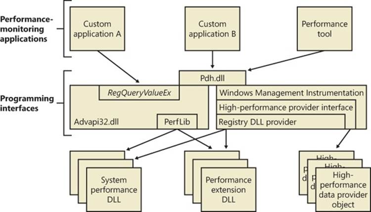
Figure 4-2. Registry performance counter architecture
Transactional Registry (TxR)
Thanks to the Kernel Transaction Manager (KTM; for more information see the section about the KTM in Chapter 3), developers have access to a straightforward API that allows them to implement robust error-recovery capabilities when performing registry operations, which can be linked with nonregistry operations, such as file or database operations.
Three APIs support transactional modification of the registry: RegCreateKeyTransacted, RegOpenKeyTransacted, and RegDeleteKeyTransacted. These new routines take the same parameters as their nontransacted analogs, except that a new transaction handle parameter is added. A developer supplies this handle after calling the KTM function CreateTransaction.
After a transacted create or open operation, all subsequent registry operations—such as creating, deleting, or modifying values inside the key—will also be transacted. However, operations on the subkeys of a transacted key will not be automatically transacted, which is why the third API, RegDeleteKeyTransacted exists. It allows the transacted deletion of subkeys, which RegDeleteKeyEx would not normally do.
Data for these transacted operations is written to log files using the common logging file system (CLFS) services, similar to other KTM operations. Until the transaction itself is committed or rolled back (both of which might happen programmatically or as a result of a power failure or system crash, depending on the state of the transaction), the keys, values, and other registry modifications performed with the transaction handle will not be visible to external applications through the nontransacted APIs. Also, transactions are isolated from each other; modifications made inside one transaction will not be visible from inside other transactions or outside the transaction until the transaction is committed.
NOTE
A nontransactional writer will abort a transaction in case of conflict—for example, if a value was created inside a transaction and later, while the transaction is still active, a nontransactional writer tries to create a value under the same key. The nontransactional operation will succeed, and all operations in the conflicting transaction will be aborted.
The isolation level (the “I” in ACID) implemented by TxR resource managers is read-commit, which means that changes become available to other readers (transacted or not) immediately after being committed. This mechanism is important for people who are familiar with transactions in databases, where the isolation level is predictable-reads (or cursor-stability, as it is called in database literature). With a predictable-reads isolation level, after you read a value inside a transaction, subsequent reads will give you back the same data. Read-commit does not make this guarantee. One of the consequences is that registry transactions can’t be used for “atomic” increment/decrement operations on a registry value.
To make permanent changes to the registry, the application that has been using the transaction handle must call the KTM function CommitTransaction. (If the application decides to undo the changes, such as during a failure path, it can call the RollbackTransaction API.) The changes will then be visible through the regular registry APIs as well.
NOTE
If a transaction handle created with CreateTransaction is closed before the transaction is committed (and there are no other handles open to that transaction), the system will roll back that transaction.
Apart from using the CLFS support provided by the KTM, TxR also stores its own internal log files in the %SystemRoot%\System32\Config\Txr folder on the system volume; these files have a .regtrans-ms extension and are hidden by default. Even if there are no third-party applications installed, your system likely will contain files in this directory because Windows Update and Component Based Servicing make use of TxR to atomically write data to the registry to avoid system failure or inconsistent component data in the case of an incomplete update. In fact, if you take a look at some of the transaction files, you should be able to see the key names on which the transaction was being performed.
There is a global registry resource manager (RM) that services all the hives that are mounted at boot time. For every hive that is mounted explicitly, an RM is created. For applications that use registry transactions, the creation of an RM is transparent because KTM ensures that all RMs taking part in the same transaction are coordinated in the two-phase commit/abort protocol. For the global registry RM, the CLFS log files are stored, as mentioned earlier, inside System32\Config\Txr. For other hives, they are stored alongside the hive (in the same directory). They are hidden and follow the same naming convention, ending in .regtrans-ms. The log file names are prefixed with the name of the hive to which they correspond.
Monitoring Registry Activity
Because the system and applications depend so heavily on configuration settings to guide their behavior, system and application failures can result from changing registry data or security. When the system or an application fails to read settings that it assumes it will always be able to access, it might not function properly, display error messages that hide the root cause, or even crash. It’s virtually impossible to know what registry keys or values are misconfigured without understanding how the system or the application that’s failing is accessing the registry. In such situations, the Process Monitor utility from Windows Sysinternals (http://technet.microsoft.com/sysinternals) might provide the answer.
Process Monitor lets you monitor registry activity as it occurs. For each registry access, Process Monitor shows you the process that performed the access; the time, type, and result of the access; and the stack of the thread at the moment of the access. This information is useful for seeing how applications and the system rely on the registry, discovering where applications and the system store configuration settings, and troubleshooting problems related to applications having missing registry keys or values. Process Monitor includes advanced filtering and highlighting so that you can zoom in on activity related to specific keys or values or to the activity of particular processes.
Process Monitor Internals
Process Monitor relies on a device driver that it extracts from its executable image at run time and then starts. Its first execution requires that the account running it have the Load Driver privilege as well as the Debug privilege; subsequent executions in the same boot session require only the Debug privilege because, once loaded, the driver remains resident.
EXPERIMENT: VIEWING REGISTRY ACTIVITY ON AN IDLE SYSTEM
Because the registry implements the RegNotifyChangeKey function that applications can use to request notification of registry changes without polling for them, when you launch Process Monitor on a system that’s idle you should not see repetitive accesses to the same registry keys or values. Any such activity identifies a poorly written application that unnecessarily negatively affects a system’s overall performance.
Run Process Monitor, and after several seconds examine the output log to see whether you can spot polling behavior. Right-click on an output line associated with polling, and then choose Process Properties from the context menu to view details about the process performing the activity.
EXPERIMENT: USING PROCESS MONITOR TO LOCATE APPLICATION REGISTRY SETTINGS
In some troubleshooting scenarios, you might need to determine where in the registry the system or an application stores particular settings. This experiment has you use Process Monitor to discover the location of Notepad’s settings. Notepad, like most Windows applications, saves user preferences—such as word-wrap mode, font and font size, and window position—across executions. By having Process Monitor watching when Notepad reads or writes its settings, you can identify the registry key in which the settings are stored. Here are the steps for doing this:
1. Have Notepad save a setting you can easily search for in a Process Monitor trace. You can do this by running Notepad, setting the font to Times New Roman, and then exiting Notepad.
2. Run Process Monitor. Open the filter dialog box and the Process Name filter, and type notepad.exe as the string to match. This step specifies that Process Monitor will log only activity by the notepad.exe process.
3. Run Notepad again, and after it has launched stop Process Monitor’s event capture by toggling Capture Events on the Process Monitor File menu.
4. Scroll to the top line of the resultant log and select it.
5. Press Ctrl+F to open a Find dialog box, and search for times new. Process Monitor should highlight a line like the one shown in the following screen that represents Notepad reading the font value from the registry. Other operations in the immediate vicinity should relate to other Notepad settings.
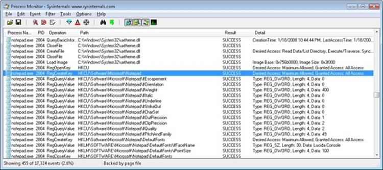
6. Finally, right-click the highlighted line and click Jump To. Process Monitor will execute Regedit (if it’s not already running) and cause it to navigate to and select the Notepad-referenced registry value.
Process Monitor Troubleshooting Techniques
Two basic Process Monitor troubleshooting techniques are effective for discovering the cause of registry-related application or system problems:
§ Look at the last thing in the Process Monitor trace that the application did before it failed. This action might point to the problem.
§ Compare a Process Monitor trace of the failing application with a trace from a working system.
To follow the first approach, run Process Monitor and then run the application. At the point the failure occurs, go back to Process Monitor and stop the logging (by pressing Ctrl+E). Then go to the end of the log and find the last operations performed by the application before it failed (or crashed, hung, or whatever). Starting with the last line, work your way backward, examining the files, registry keys, or both that were referenced—often this will help pinpoint the problem.
Use the second approach when the application fails on one system but works on another. Capture a Process Monitor trace of the application on the working and failing systems, and save the output to a log file. Then open the good and bad log files with Microsoft Excel (accepting the defaults in the Import wizard), and delete the first three columns. (If you don’t delete the first three columns, the comparison will show every line as different because the first three columns contain information that is different from run to run, such as the time and the process ID.) Finally, compare the resulting log files. (You can do this by using WinDiff, which is included in the Windows SDK).
Entries in a Process Monitor trace that have values of NAME NOT FOUND or ACCESS DENIED in the Result column are ones you should investigate. NAME NOT FOUND is reported when an application attempts to read from a registry key or value that doesn’t exist. In many cases, a missing key or value is innocuous because a process that fails to read a setting from the registry simply falls back on default values. In some cases, however, applications expect to find values for which there is no default and will fail if they are missing.
Access-denied errors are a common source of registry-related application failures and occur when an application doesn’t have permission to access a key the way that it wants. Applications that do not validate registry operation results or perform proper error recovery will fail.
A common result string that might appear suspicious is BUFFER OVERFLOW. It does not indicate a buffer-overflow exploit in the application that receives it. Instead, it’s used by the configuration manager to inform an application that the buffer it specified to store a registry value is too small to hold the value. Application developers often take advantage of this behavior to determine how large a buffer to allocate to store a value. They first perform a registry query with a zero-length buffer that returns a buffer-overflow error and the length of the data it attempted to read. The application then allocates a buffer of the indicated size and rereads the value. You should therefore see operations that return BUFFER OVERFLOW repeat with a successful result.
In one example of Process Monitor being used to troubleshoot a real problem, it saved a user from doing a complete reinstall of his Windows system. The symptom was that Internet Explorer would hang on startup if the user did not first manually dial the Internet connection. This Internet connection was set as the default connection for the system, so starting Internet Explorer should have caused an automatic dial-up to the Internet (because Internet Explorer was set to display a default home page upon startup).
An examination of a Process Monitor log of Internet Explorer startup activity, going backward from the point in the log where Internet Explorer hung, showed a query to a key under HKCU\Software\Microsoft\RAS Phonebook. The user reported that he had previously uninstalled the dialer program associated with the key and manually created the dial-up connection. Because the dial-up connection name did not match that of the uninstalled dialer program, it appeared that the key had not been deleted by the dialer’s uninstall program and that it was causing Internet Explorer to hang. After the key was deleted, Internet Explorer functioned as expected.
Logging Activity in Unprivileged Accounts or During Logon/Logoff
A common application-failure scenario is that an application works when run in an account that has Administrative group membership but not when run in the account of an unprivileged user. As described earlier, executing Process Monitor requires security privileges that are not normally assigned to standard user accounts, but you can capture a trace of applications executing in the logon session of an unprivileged user by using the Runas command to execute Process Monitor in an administrative account.
If a registry problem relates to account logon or logoff, you’ll also have to take special steps to be able to use Process Monitor to capture a trace of those phases of a logon session. Applications that are run in the local system account are not terminated when a user logs off, and you can take advantage of that fact to have Process Monitor run through a logoff and subsequent logon. You can launch Process Monitor in the local system account either by using the At command that’s built into Windows and specifying the /interactive flag, or by using the Sysinternals PsExec utility, like this:
§ psexec –i 0 –s –d c:\procmon.exe
The –i 0 switch directs PsExec to have Process Monitor’s window appear on the session 0 interactive window station’s default desktop, the –s switch has PsExec run Process Monitor in the local system account, and the –d switch has PsExec launch Process Monitor and exit without waiting for Process Monitor to terminate. When you execute this command, the instance of Process Monitor that executes will survive logoff and reappear on the desktop when you log back on, having captured the registry activity of both actions.
Another way to monitor registry activity during the logon, logoff, boot, or shutdown process is to use the Process Monitor log boot feature, which you can enable by selecting Log Boot on the Options menu. The next time you boot the system, the Process Monitor device driver logs registry activity from early in the boot to %SystemRoot%\Procmon.pml. It will continue logging to that file until disk space runs out, the system shuts down, or you run Process Monitor. A log file storing a registry trace of startup, logon, logoff, and shutdown on a Windows system will typically be between 50 and 150 MB in size.
Registry Internals
In this section, you’ll find out how the configuration manager—the executive subsystem that implements the registry—organizes the registry’s on-disk files. We’ll examine how the configuration manager manages the registry as applications and other operating system components read and change registry keys and values. We’ll also discuss the mechanisms by which the configuration manager tries to ensure that the registry is always in a recoverable state, even if the system crashes while the registry is being modified.
Hives
On disk, the registry isn’t simply one large file but rather a set of discrete files called hives. Each hive contains a registry tree, which has a key that serves as the root or starting point of the tree. Subkeys and their values reside beneath the root. You might think that the root keys displayed by the Registry Editor correlate to the root keys in the hives, but such is not the case. Table 4-5 lists registry hives and their on-disk file names. The path names of all hives except for user profiles are coded into the configuration manager. As the configuration manager loads hives, including system profiles, it notes each hive’s path in the values under the HKLM\SYSTEM\CurrentControlSet\Control\Hivelist subkey, removing the path if the hive is unloaded. It creates the root keys, linking these hives together to build the registry structure you’re familiar with and that the Registry Editor displays.
You’ll notice that some of the hives listed in Table 4-5 are volatile and don’t have associated files. The system creates and manages these hives entirely in memory; the hives are therefore temporary. The system creates volatile hives every time it boots. An example of a volatile hive is the HKLM\HARDWARE hive, which stores information about physical devices and the devices’ assigned resources. Resource assignment and hardware detection occur every time the system boots, so not storing this data on disk is logical.
Table 4-5. On-Disk Files Corresponding to Paths in the Registry
|
Hive Registry Path |
Hive File Path |
|
HKEY_LOCAL_MACHINE\BCD00000000 |
\Boot\BCD |
|
HKEY_LOCAL_MACHINE\COMPONENTS |
%SystemRoot%\System32\Config\Components |
|
HKEY_LOCAL_MACHINE\SYSTEM |
%SystemRoot%\System32\Config\System |
|
HKEY_LOCAL_MACHINE\SAM |
%SystemRoot%\System32\Config\Sam |
|
HKEY_LOCAL_MACHINE\SECURITY |
%SystemRoot%\System32\Config\Security |
|
HKEY_LOCAL_MACHINE\SOFTWARE |
%SystemRoot%\System32\Config\Software |
|
HKEY_LOCAL_MACHINE\HARDWARE |
Volatile hive |
|
HKEY_USERS\<SID of local service account> |
%SystemRoot%\ServiceProfiles\LocalService\Ntuser.dat |
|
HKEY_USERS\<SID of network service account> |
%SystemRoot%\ServiceProfiles\NetworkService\NtUser.dat |
|
HKEY_USERS\<SID of username> |
\Users\<username>\Ntuser.dat |
|
HKEY_USERS\<SID of username>_Classes |
\Users\<username>\AppData\Local\Microsoft\Windows\Usrclass.dat |
|
HKEY_USERS\.DEFAULT |
%SystemRoot%\System32\Config\Default |
EXPERIMENT: MANUALLY LOADING AND UNLOADING HIVES
Regedit has the ability to load hives that you can access through its File menu. This capability can be useful in troubleshooting scenarios where you want to view or edit a hive from an unbootable system or a backup medium. In this experiment, you’ll use Regedit to load a version of the HKLM\SYSTEM hive that Windows Setup creates during the install process.
1. Hives can be loaded only underneath HKLM or HKU, so open Regedit, select HKLM, and choose Load Hive from the Regedit File menu.
2. Navigate to the %SystemRoot%\System32\Config\RegBack directory in the Load Hive dialog box, select System and open it. When prompted, type Test as the name of the key under which it will load.
3. Open the newly created HKLM\Test key, and explore the contents of the hive.
4. Open HKLM\SYSTEM\CurrentControlSet\Control\Hivelist, and locate the entry \Registry\Machine\Test, which demonstrates how the configuration manager lists loaded hives in the Hivelist key.
5. Select HKLM\Test, and then choose Unload Hive from the Regedit File menu to unload the hive.
Hive Size Limits
In some cases, hive sizes are limited. For example, Windows places a limit on the size of the HKLM\SYSTEM hive. It does so because Winload reads the entire HKLM\SYSTEM hive into physical memory near the start of the boot process when virtual memory paging is not enabled. Winload also loads Ntoskrnl and boot device drivers into physical memory, so it must constrain the amount of physical memory assigned to HKLM\SYSTEM. (See Chapter 13 in Part 2 for more information on the role Winload plays during the startup process.) On 32-bit systems, Winload allows the hive to be as large as 400 MB or one-half the amount of physical memory on the system, whichever is lower. On x64 systems, the lower bound is 1.5 GB. On Itanium systems, it is 32 MB.
Registry Symbolic Links
A special type of key known as a registry symbolic link makes it possible for the configuration manager to link keys to organize the registry. A symbolic link is a key that redirects the configuration manager to another key. Thus, the key HKLM\SAM is a symbolic link to the key at the root of the SAM hive. Symbolic links are created by specifying the REG_CREATE_LINK parameter to RegCreateKey or RegCreateKeyEx. Internally, the configuration manager will create a REG_LINK value called SymbolicLinkValue, which will contain the path to the target key. Because this value is a REG_LINK instead of a REG_SZ, it will not be visible with Regedit—it is, however, part of the on-disk registry hive.
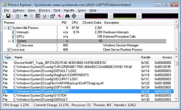
EXPERIMENT: LOOKING AT HIVE HANDLES
The configuration manager opens hives by using the kernel handle table (described in Chapter 3) so that it can access hives from any process context. Using the kernel handle table is an efficient alternative to approaches that involve using drivers or executive components to access from the System process only handles that must be protected from user processes. You can use Process Explorer to see the hive handles, which will be displayed as being opened in the System process. Select the System process, and then select Handles from the Lower Pane View menu entry on the View menu. Sort by handle type, and scroll until you see the hive files, as shown in the following screen.
Hive Structure
The configuration manager logically divides a hive into allocation units called blocks in much the same way that a file system divides a disk into clusters. By definition, the registry block size is 4096 bytes (4 KB). When new data expands a hive, the hive always expands in block-granular increments. The first block of a hive is the base block.
The base block includes global information about the hive, including a signature—regf—that identifies the file as a hive, updated sequence numbers, a time stamp that shows the last time a write operation was initiated on the hive, information on registry repair or recovery performed by Winload, the hive format version number, a checksum, and the hive file’s internal file name (for example, \Device\HarddiskVolume1\WINDOWS\SYSTEM32\CONFIG\SAM). We’ll clarify the significance of the updated sequence numbers and time stamp when we describe how data is written to a hive file.
The hive format version number specifies the data format within the hive. The configuration manager uses hive format version 1.3 (which improved searching by caching the first four characters of the name inside the cell index structure for quick lookups) for all hives except for System and Software for roaming profile compatibility with Windows 2000. For System and Software hives, it uses version 1.5 because of the later format’s optimizations for large values (values larger than 1 MB are supported) and searching (instead of caching the first four characters of a name, a hash of the entire name is used to reduce collisions).
Windows organizes the registry data that a hive stores in containers called cells. A cell can hold a key, a value, a security descriptor, a list of subkeys, or a list of key values. A 4-byte character tag at the beginning of a cell’s data describes the data’s type as a signature. Table 4-6describes each cell data type in detail. A cell’s header is a field that specifies the cell’s size as the 1’s complement (not present in the CM_ structures). When a cell joins a hive and the hive must expand to contain the cell, the system creates an allocation unit called a bin.
A bin is the size of the new cell rounded up to the next block or page boundary, whichever is higher. The system considers any space between the end of the cell and the end of the bin to be free space that it can allocate to other cells. Bins also have headers that contain a signature, hbin, and a field that records the offset into the hive file of the bin and the bin’s size.
Table 4-6. Cell Data Types
|
Data Type |
Structure Type |
Description |
|
Key cell |
CM_KEY_NODE |
A cell that contains a registry key, also called a key node. A key cell contains a signature (kn for a key, kl for a link node), the time stamp of the most recent update to the key, the cell index of the key’s parent key cell, the cell index of the subkey-list cell that identifies the key’s subkeys, a cell index for the key’s security descriptor cell, a cell index for a string key that specifies the class name of the key, and the name of the key (for example, CurrentControlSet). It also saves cached information such as the number of subkeys under the key, as well as the size of the largest key, value name, value data, and class name of the subkeys under this key. |
|
Value cell |
CM_KEY_VALUE |
A cell that contains information about a key’s value. This cell includes a signature (kv), the value’s type (for example, REG_ DWORD or REG_BINARY), and the value’s name (for example, Boot-Execute). A value cell also contains the cell index of the cell that contains the value’s data. |
|
Subkey-list cell |
CM_KEY_INDEX |
A cell composed of a list of cell indexes for key cells that are all subkeys of a common parent key. |
|
Value-list cell |
CM_KEY_INDEX |
A cell composed of a list of cell indexes for value cells that are all values of a common parent key. |
|
Security-descriptor cell |
CM_KEY_SECURITY |
A cell that contains a security descriptor. Security-descriptor cells include a signature (ks) at the head of the cell and a reference count that records the number of key nodes that share the security descriptor. Multiple key cells can share security-descriptor cells. |
By using bins, instead of cells, to track active parts of the registry, Windows minimizes some management chores. For example, the system usually allocates and deallocates bins less frequently than it does cells, which lets the configuration manager manage memory more efficiently. When the configuration manager reads a registry hive into memory, it reads the whole hive, including empty bins, but it can choose to discard them later. When the system adds and deletes cells in a hive, the hive can contain empty bins interspersed with active bins. This situation is similar to disk fragmentation, which occurs when the system creates and deletes files on the disk. When a bin becomes empty, the configuration manager joins to the empty bin any adjacent empty bins to form as large a contiguous empty bin as possible. The configuration manager also joins adjacent deleted cells to form larger free cells. (The configuration manager shrinks a hive only when bins at the end of the hive become free. You can compact the registry by backing it up and restoring it using the Windows RegSaveKey and RegReplaceKey functions, which are used by the Windows Backup utility.)
The links that create the structure of a hive are called cell indexes. A cell index is the offset of a cell into the hive file minus the size of the base block. Thus, a cell index is like a pointer from one cell to another cell that the configuration manager interprets relative to the start of a hive. For example, as you saw in Table 4-6, a cell that describes a key contains a field specifying the cell index of its parent key; a cell index for a subkey specifies the cell that describes the subkeys that are subordinate to the specified subkey. A subkey-list cell contains a list of cell indexes that refer to the subkey’s key cells. Therefore, if you want to locate, for example, the key cell of subkey A, whose parent is key B, you must first locate the cell containing key B’s subkey list using the subkey-list cell index in key B’s cell. Then you locate each of key B’s subkey cells by using the list of cell indexes in the subkey-list cell. For each subkey cell, you check to see whether the subkey’s name, which a key cell stores, matches the one you want to locate, in this case, subkey A.
The distinction between cells, bins, and blocks can be confusing, so let’s look at an example of a simple registry hive layout to help clarify the differences. The sample registry hive file in Figure 4-3 contains a base block and two bins. The first bin is empty, and the second bin contains several cells. Logically, the hive has only two keys: the root key Root, and a subkey of Root, Sub Key. Root has two values, Val 1 and Val 2. A subkey-list cell locates the root key’s subkey, and a value-list cell locates the root key’s values. The free spaces in the second bin are empty cells. Figure 4-3 doesn’t show the security cells for the two keys, which would be present in a hive.
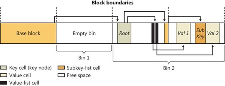
Figure 4-3. Internal structure of a registry hive
To optimize searches for both values and subkeys, the configuration manager sorts subkey-list cells alphabetically. The configuration manager can then perform a binary search when it looks for a subkey within a list of subkeys. The configuration manager examines the subkey in the middle of the list, and if the name of the subkey the configuration manager is looking for is alphabetically before the name of the middle subkey, the configuration manager knows that the subkey is in the first half of the subkey list; otherwise, the subkey is in the second half of the subkey list. This splitting process continues until the configuration manager locates the subkey or finds no match. Value-list cells aren’t sorted, however, so new values are always added to the end of the list.
Cell Maps
If hives never grew, the configuration manager could perform all its registry management on the in-memory version of a hive as if the hive were a file. Given a cell index, the configuration manager could calculate the location in memory of a cell simply by adding the cell index, which is a hive file offset, to the base of the in-memory hive image. Early in the system boot, this process is exactly what Winload does with the SYSTEM hive: Winload reads the entire SYSTEM hive into memory as a read-only hive and adds the cell indexes to the base of the in-memory hive image to locate cells. Unfortunately, hives grow as they take on new keys and values, which means the system must allocate paged pool memory to store the new bins that contain added keys and values. Thus, the paged pool that keeps the registry data in memory isn’t necessarily contiguous.
EXPERIMENT: VIEWING HIVE PAGED POOL USAGE
There are no administrative-level tools that show you the amount of paged pool that registry hives, including user profiles, are consuming on Windows. However, the !reg dumppool kernel debugger command shows you not only how many pages of the paged pool each loaded hive consumes but also how many of the pages store volatile and nonvolatile data. The command prints the total hive memory usage at the end of the output. (The command shows only the last 32 characters of a hive’s name.)
kd> !reg dumppool
dumping hive at e20d66a8 (a\Microsoft\Windows\UsrClass.dat)
Stable Length = 1000
1/1 pages present
Volatile Length = 0
dumping hive at e215ee88 (ettings\Administrator\ntuser.dat)
Stable Length = f2000
242/242 pages present
Volatile Length = 2000
2/2 pages present
dumping hive at e13fa188 (\SystemRoot\System32\Config\SAM)
Stable Length = 5000
5/5 pages present
Volatile Length = 0
...
To deal with noncontiguous memory addresses referencing hive data in memory, the configuration manager adopts a strategy similar to what the Windows memory manager uses to map virtual memory addresses to physical memory addresses. The configuration manager employs a two-level scheme, which Figure 4-4 illustrates, that takes as input a cell index (that is, a hive file offset) and returns as output both the address in memory of the block the cell index resides in and the address in memory of the block the cell resides in. Remember that a bin can contain one or more blocks and that hives grow in bins, so Windows always represents a bin with a contiguous region of memory. Therefore, all blocks within a bin occur within the same cache manager view.
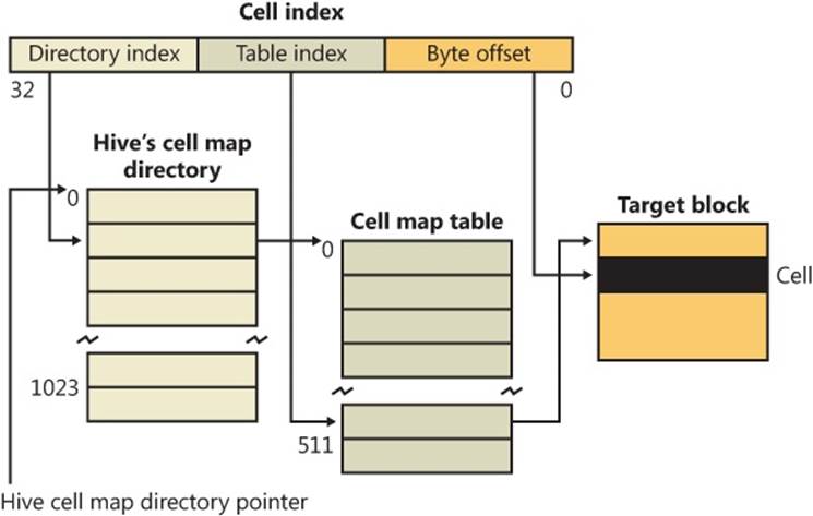
Figure 4-4. Structure of a cell index
To implement the mapping, the configuration manager divides a cell index logically into fields, in the same way that the memory manager divides a virtual address into fields. Windows interprets a cell index’s first field as an index into a hive’s cell map directory. The cell map directory contains 1024 entries, each of which refers to a cell map table that contains 512 map entries. An entry in this cell map table is specified by the second field in the cell index. That entry locates the bin and block memory addresses of the cell. Not all bins are necessarily mapped into memory, and if a cell lookup yields an address of 0, the configuration manager maps the bin into memory, unmapping another on the mapping LRU list it maintains, if necessary.
In the final step of the translation process, the configuration manager interprets the last field of the cell index as an offset into the identified block to precisely locate a cell in memory. When a hive initializes, the configuration manager dynamically creates the mapping tables, designating a map entry for each block in the hive, and it adds and deletes tables from the cell directory as the changing size of the hive requires.
The Registry Namespace and Operation
The configuration manager defines a key object type to integrate the registry’s namespace with the kernel’s general namespace. The configuration manager inserts a key object named Registry into the root of the Windows namespace, which serves as the entry point to the registry. Regedit shows key names in the form HKEY_LOCAL_MACHINE\SYSTEM\CurrentControlSet, but the Windows subsystem translates such names into their object namespace form (for example, \Registry\Machine\System\CurrentControlSet). When the Windows object manager parses this name, it encounters the key object by the name of Registry first and hands the rest of the name to the configuration manager. The configuration manager takes over the name parsing, looking through its internal hive tree to find the desired key or value. Before we describe the flow of control for a typical registry operation, we need to discuss key objects and key control blocks. Whenever an application opens or creates a registry key, the object manager gives a handle with which to reference the key to the application. The handle corresponds to a key object that the configuration manager allocates with the help of the object manager. By using the object manager’s object support, the configuration manager takes advantage of the security and reference-counting functionality that the object manager provides.
For each open registry key, the configuration manager also allocates a key control block. A key control block stores the name of the key, includes the cell index of the key node that the control block refers to, and contains a flag that notes whether the configuration manager needs to delete the key cell that the key control block refers to when the last handle for the key closes. Windows places all key control blocks into a hash table to enable quick searches for existing key control blocks by name. A key object points to its corresponding key control block, so if two applications open the same registry key, each will receive a key object, and both key objects will point to a common key control block.
When an application opens an existing registry key, the flow of control starts with the application specifying the name of the key in a registry API that invokes the object manager’s name-parsing routine. The object manager, upon encountering the configuration manager’s registry key object in the namespace, hands the path name to the configuration manager. The configuration manager performs a lookup on the key control block hash table. If the related key control block is found there, there’s no need for any further work; otherwise, the lookup provides the configuration manager with the closest key control block to the searched key, and the lookup continues by using the in-memory hive data structures to search through keys and subkeys to find the specified key. If the configuration manager finds the key cell, the configuration manager searches the key control block tree to determine whether the key is open (by the same application or another one). The search routine is optimized to always start from the closest ancestor with a key control block already opened. For example, if an application opens \Registry\Machine\Key1\Subkey2, and \Registry\Machine is already opened, the parse routine uses the key control block of \Registry\Machine as a starting point. If the key is open, the configuration manager increments the existing key control block’s reference count. If the key isn’t open, the configuration manager allocates a new key control block and inserts it into the tree. Then the configuration manager allocates a key object, points the key object at the key control block, and returns control to the object manager, which returns a handle to the application.
When an application creates a new registry key, the configuration manager first finds the key cell for the new key’s parent. The configuration manager then searches the list of free cells for the hive in which the new key will reside to determine whether cells exist that are large enough to hold the new key cell. If there aren’t any free cells large enough, the configuration manager allocates a new bin and uses it for the cell, placing any space at the end of the bin on the free cell list. The new key cell fills with pertinent information—including the key’s name—and the configuration manager adds the key cell to the subkey list of the parent key’s subkey-list cell. Finally, the system stores the cell index of the parent cell in the new subkey’s key cell.
The configuration manager uses a key control block’s reference count to determine when to delete the key control block. When all the handles that refer to a key in a key control block close, the reference count becomes 0, which denotes that the key control block is no longer necessary. If an application that calls an API to delete the key sets the delete flag, the configuration manager can delete the associated key from the key’s hive because it knows that no application is keeping the key open.
EXPERIMENT: VIEWING KEY CONTROL BLOCKS
You can use the kernel debugger to list all the key control blocks allocated on a system with the command !reg openkeys command. Alternatively, if you want to view the key control block for a particular open key, use !reg findkcb:
kd> !reg findkcb \registry\machine\software\microsoft
Found KCB = e1034d40 :: \REGISTRY\MACHINE\SOFTWARE\MICROSOFT
You can then examine a reported key control block with the !reg kcb command:
kd> !reg kcb e1034d40
Key : \REGISTRY\MACHINE\SOFTWARE\MICROSOFT
RefCount : 1f
Flags : CompressedName, Stable
ExtFlags :
Parent : 0xe1997368
KeyHive : 0xe1c8a768
KeyCell : 0x64e598 [cell index]
TotalLevels : 4
DelayedCloseIndex: 2048
MaxNameLen : 0x3c
MaxValueNameLen : 0x0
MaxValueDataLen : 0x0
LastWriteTime : 0x 1c42501:0x7eb6d470
KeyBodyListHead : 0xe1034d70 0xe1034d70
SubKeyCount : 137
ValueCache.Count : 0
KCBLock : 0xe1034d40
KeyLock : 0xe1034d40
The Flags field indicates that the name is stored in compressed form, and the SubKeyCount field shows that the key has 137 subkeys.
Stable Storage
To make sure that a nonvolatile registry hive (one with an on-disk file) is always in a recoverable state, the configuration manager uses log hives. Each nonvolatile hive has an associated log hive, which is a hidden file with the same base name as the hive and a logN extension. To ensure forward progress, the configuration manger uses a dual-logging scheme. There are potentially two log files: .log1 and .log2. If, for any reason, .log1 was written but a failure occurred while writing dirty data to the primary log file, the next time a flush happens, a switch to .log2 will occur with the cumulative dirty data. If that fails as well, the cumulative dirty data (the data in .log1 and the data that was dirtied in between) is saved in .log2. As a consequence, .log1 will be used again next time around, until a successful write operation is done to the primary log file. If no failure occurs, only .log1 is used.
For example, if you look in your %SystemRoot%\System32\Config directory (and you have the Show Hidden Files And Folders folder option selected), you’ll see System.log1, Sam.log1, and other .log1 and .log2 files. When a hive initializes, the configuration manager allocates a bit array in which each bit represents a 512-byte portion, or sector, of the hive. This array is called the dirty sector array because an on bit in the array means that the system has modified the corresponding sector in the hive in memory and must write the sector back to the hive file. (An off bit means that the corresponding sector is up to date with the in-memory hive’s contents.)
When the creation of a new key or value or the modification of an existing key or value takes place, the configuration manager notes the sectors of the hive that change in the hive’s dirty sector array. Then the configuration manager schedules a lazy write operation, or a hive sync. The hive lazy writer system thread wakes up five seconds after the request to synchronize the hive and writes dirty hive sectors for all hives from memory to the hive files on disk. Thus, the system flushes, at the same time, all the registry modifications that take place between the time a hive sync is requested and the time the hive sync occurs. When a hive sync takes place, the next hive sync will occur no sooner than five seconds later.
NOTE
The RegFlushKey API’s name implies that the function flushes only modified data for a specified key to disk, but it actually triggers a full registry flush, which has a major performance impact on the system. For that reason and the fact that the registry automatically makes sure that modified data is in stable storage within seconds, application programmers should avoid using it.
If the lazy writer simply wrote all a hive’s dirty sectors to the hive file and the system crashed in mid-operation, the hive file would be in an inconsistent (corrupted) and unrecoverable state. To prevent such an occurrence, the lazy writer first dumps the hive’s dirty sector array and all the dirty sectors to the hive’s log file, increasing the log file’s size if necessary. The lazy writer then updates a sequence number in the hive’s base block and writes the dirty sectors to the hive. When the lazy writer is finished, it updates a second sequence number in the base block. Thus, if the system crashes during the write operations to the hive, at the next reboot the configuration manager will notice that the two sequence numbers in the hive’s base block don’t match. The configuration manager can update the hive with the dirty sectors in the hive’s log file to roll the hive forward. The hive is then up to date and consistent.
The Windows Boot Loader also contains some code related to registry reliability. For example, it can parse the System.log file before the kernel is loaded and do repairs to fix consistency. Additionally, in certain cases of hive corruption (such as if a base block, bin, or cell contains data that fails consistency checks), the configuration manager can reinitialize corrupted data structures, possibly deleting subkeys in the process, and continue normal operation. If it has to resort to a self-healing operation, it pops up a system error dialog box notifying the user.
Registry Filtering
The configuration manager in the Windows kernel implements a powerful model of registry filtering, which allows for monitoring of registry activity by tools such as Process Monitor. When a driver uses the callback mechanism, it registers a callback function with the configuration manager. The configuration manager executes the driver’s callback function before and after the execution of registry system services so that the driver has full visibility and control over registry accesses. Antivirus products that scan registry data for viruses or prevent unauthorized processes from modifying the registry are other users of the callback mechanism.
Registry callbacks are also associated with the concept of altitudes. Altitudes are a way for different vendors to register a “height” on the registry filtering stack so that the order in which the system calls each callback routine can be deterministic and correct. This avoids a scenario in which an antivirus product would be scanning encrypted keys before an encryption product would run its own callback to decrypt them. With the Windows registry callback model, both types of tools are assigned a base altitude corresponding to the type of filtering they are doing—in this case, encryption versus scanning. Secondly, companies that create these types of tools must register with Microsoft so that within their own group, they will not collide with similar or competing products.
The filtering model also includes the ability to either completely take over the processing of the registry operation (bypassing the configuration manager and preventing it from handling the request) or redirect the operation to a different operation (such as Wow64’s registry redirection). Additionally, it is also possible to modify the output parameters as well as the return value of a registry operation.
Finally, drivers can assign and tag per-key or per-operation driver-defined information for their own purposes. A driver can create and assign this context data during a create or open operation, which the configuration manager will remember and return during each subsequent operation on the key.
Registry Optimizations
The configuration manager makes a few noteworthy performance optimizations. First, virtually every registry key has a security descriptor that protects access to the key. Storing a unique security-descriptor copy for every key in a hive would be highly inefficient, however, because the same security settings often apply to entire subtrees of the registry. When the system applies security to a key, the configuration manager checks a pool of the unique security descriptors used within the same hive as the key to which new security is being applied, and it shares any existing descriptor for the key, ensuring that there is at most one copy of every unique security descriptor in a hive.
The configuration manager also optimizes the way it stores key and value names in a hive. Although the registry is fully Unicode-capable and specifies all names using the Unicode convention, if a name contains only ASCII characters, the configuration manager stores the name in ASCII form in the hive. When the configuration manager reads the name (such as when performing name lookups), it converts the name into Unicode form in memory. Storing the name in ASCII form can significantly reduce the size of a hive.
To minimize memory usage, key control blocks don’t store full key registry path names. Instead, they reference only a key’s name. For example, a key control block that refers to \Registry\System\Control would refer to the name Control rather than to the full path. A further memory optimization is that the configuration manager uses key name control blocks to store key names, and all key control blocks for keys with the same name share the same key name control block. To optimize performance, the configuration manager stores the key control block names in a hash table for quick lookups.
To provide fast access to key control blocks, the configuration manager stores frequently accessed key control blocks in the cache table, which is configured as a hash table. When the configuration manager needs to look up a key control block, it first checks the cache table. Finally, the configuration manager has another cache, the delayed close table, that stores key control blocks that applications close so that an application can quickly reopen a key it has recently closed. To optimize lookups, these cache tables are stored for each hive. The configuration manager removes the oldest key control blocks from the delayed close table as it adds the most recently closed blocks to the table.
Services
Almost every operating system has a mechanism to start processes at system startup time that provide services not tied to an interactive user. In Windows, such processes are called services or Windows services, because they rely on the Windows API to interact with the system. Services are similar to UNIX daemon processes and often implement the server side of client/server applications. An example of a Windows service might be a web server, because it must be running regardless of whether anyone is logged on to the computer and it must start running when the system starts so that an administrator doesn’t have to remember, or even be present, to start it.
Windows services consist of three components: a service application, a service control program (SCP), and the service control manager (SCM). First, we’ll describe service applications, service accounts, and the operations of the SCM. Then we’ll explain how auto-start services are started during the system boot. We’ll also cover the steps the SCM takes when a service fails during its startup and the way the SCM shuts down services.
Service Applications
Service applications, such as web servers, consist of at least one executable that runs as a Windows service. A user wanting to start, stop, or configure a service uses an SCP. Although Windows supplies built-in SCPs that provide general start, stop, pause, and continue functionality, some service applications include their own SCP that allows administrators to specify configuration settings particular to the service they manage.
Service applications are simply Windows executables (GUI or console) with additional code to receive commands from the SCM as well as to communicate the application’s status back to the SCM. Because most services don’t have a user interface, they are built as console programs.
When you install an application that includes a service, the application’s setup program must register the service with the system. To register the service, the setup program calls the Windows CreateService function, a services-related function implemented in Advapi32.dll (%SystemRoot%\System32\Advapi32.dll). Advapi32, the “Advanced API” DLL, implements all the client-side SCM APIs.
When a setup program registers a service by calling CreateService, a message is sent to the SCM on the machine where the service will reside. The SCM then creates a registry key for the service under HKLM\SYSTEM\CurrentControlSet\Services. The Services key is the nonvolatile representation of the SCM’s database. The individual keys for each service define the path of the executable image that contains the service as well as parameters and configuration options.
After creating a service, an installation or management application can start the service via the StartService function. Because some service-based applications also must initialize during the boot process to function, it’s not unusual for a setup program to register a service as an auto-start service, ask the user to reboot the system to complete an installation, and let the SCM start the service as the system boots.
When a program calls CreateService, it must specify a number of parameters describing the service’s characteristics. The characteristics include the service’s type (whether it’s a service that runs in its own process rather than a service that shares a process with other services), the location of the service’s executable image file, an optional display name, an optional account name and password used to start the service in a particular account’s security context, a start type that indicates whether the service starts automatically when the system boots or manually under the direction of an SCP, an error code that indicates how the system should react if the service detects an error when starting, and, if the service starts automatically, optional information that specifies when the service starts relative to other services.
The SCM stores each characteristic as a value in the service’s registry key. Figure 4-5 shows an example of a service registry key.
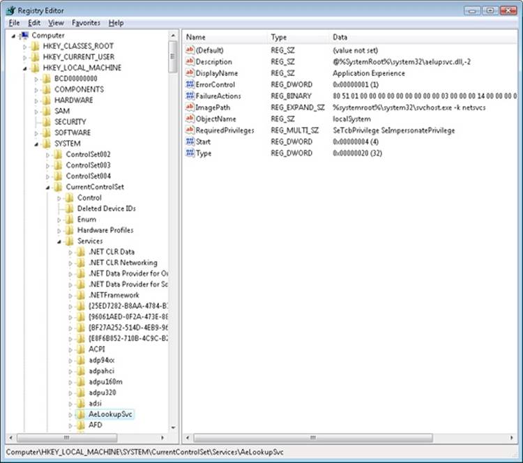
Figure 4-5. Example of a service registry key
Table 4-7 lists all the service characteristics, many of which also apply to device drivers. (Not every characteristic applies to every type of service or device driver.) If a service needs to store configuration information that is private to the service, the convention is to create a subkey named Parameters under its service key and then store the configuration information in values under that subkey. The service then can retrieve the values by using standard registry functions.
NOTE
The SCM does not access a service’s Parameters subkey until the service is deleted, at which time the SCM deletes the service’s entire key, including subkeys like Parameters.
Table 4-7. Service and Driver Registry Parameters
|
Value Setting |
Value Name |
Value Setting Description |
|
Start |
SERVICE_BOOT_START (0) |
Winload preloads the driver so that it is in memory during the boot. These drivers are initialized just prior to SERVICE_ SYSTEM_START drivers. |
|
SERVICE_SYSTEM_START (1) |
The driver loads and initializes during kernel initialization after SERVICE_ BOOT_START drivers have initialized. |
|
|
SERVICE_AUTO_START (2) |
The SCM starts the driver or service after the SCM process, Services.exe, starts. |
|
|
SERVICE_DEMAND_START (3) |
The SCM starts the driver or service on demand. |
|
|
SERVICE_DISABLED (4) |
The driver or service doesn’t load or initialize. |
|
|
ErrorControl |
SERVICE_ERROR_IGNORE (0) |
Any error the driver or service returns is ignored, and no warning is logged or displayed. |
|
SERVICE_ERROR_NORMAL (1) |
If the driver or service reports an error, an event log message is written. |
|
|
SERVICE_ERROR_SEVERE (2) |
If the driver or service returns an error and last known good isn’t being used, reboot into last known good; otherwise, continue the boot. |
|
|
SERVICE_ERROR_CRITICAL (3) |
If the driver or service returns an error and last known good isn’t being used, reboot into last known good; otherwise, stop the boot with a blue screen crash. |
|
|
Type |
SERVICE_KERNEL_DRIVER (1) |
Device driver. |
|
SERVICE_FILE_SYSTEM_DRIVER (2) |
Kernel-mode file system driver. |
|
|
SERVICE_ADAPTER (4) |
Obsolete. |
|
|
SERVICE_RECOGNIZER_DRIVER (8) |
File system recognizer driver. |
|
|
SERVICE_WIN32_OWN_PROCESS (16) |
The service runs in a process that hosts only one service. |
|
|
SERVICE_WIN32_SHARE_PROCESS (32) |
The service runs in a process that hosts multiple services. |
|
|
SERVICE_INTERACTIVE_PROCESS (256) |
The service is allowed to display windows on the console and receive user input, but only on the console session (0) to prevent interacting with user/console applications on other sessions. |
|
|
Group |
Group name |
The driver or service initializes when its group is initialized. |
|
Tag |
Tag number |
The specified location in a group initialization order. This parameter doesn’t apply to services. |
|
ImagePath |
Path to the service or driver executable file |
If ImagePath isn’t specified, the I/O manager looks for drivers in %SystemRoot%\System32\Drivers. Required for Windows services. |
|
DependOnGroup |
Group name |
The driver or service won’t load unless a driver or service from the specified group loads. |
|
DependOnService |
Service name |
The service won’t load until after the specified service loads. This parameter doesn’t apply to device drivers other than those with a start type of SERVICE_AUTO_START or SERVICE_DEMAND_START. |
|
ObjectName |
Usually LocalSystem, but it can be an account name, such as .\Administrator |
Specifies the account in which the service will run. If ObjectName isn’t specified, LocalSystem is the account used. This parameter doesn’t apply to device drivers. |
|
DisplayName |
Name of the service |
The service application shows services by this name. If no name is specified, the name of the service’s registry key becomes its name. |
|
Description |
Description of service |
Up to 32767-byte description of the service. |
|
FailureActions |
Description of actions the SCM should take when the service process exits unexpectedly |
Failure actions include restarting the service process, rebooting the system, and running a specified program. This value doesn’t apply to drivers. |
|
FailureCommand |
Program command line |
The SCM reads this value only if FailureActions specifies that a program should execute upon service failure. This value doesn’t apply to drivers. |
|
DelayedAutoStart |
0 or 1 (TRUE or FALSE) |
Tells the SCM to start this service after a certain delay has passed since the SCM was started. This reduces the number of services starting simultaneously during startup. |
|
PreshutdownTimeout |
Timeout in milliseconds |
This value allows services to override the default preshutdown notification timeout of 180 seconds. After this timeout, the SCM will perform shutdown actions on the service if it has not yet responded. |
|
ServiceSidType |
SERVICE_SID_TYPE_NONE (0) |
Backward-compatibility setting. |
|
SERVICE_SID_TYPE_UNRESTRICTED (1) |
The SCM will add the service SID as a group owner to the service process’ token when it is created. |
|
|
SERVICE_SID_TYPE_RESTRICTED (3) |
Same as above, but the SCM will also add the service SID to the restricted SID list of the service process, along with the world, logon, and write-restricted SIDs. |
|
|
RequiredPrivileges |
List of privileges |
This value contains the list of privileges that the service requires to function. The SCM will compute their union when creating the token for the shared process related to this service, if any. |
|
Security |
Security descriptor |
This value contains the optional security descriptor that defines who has what access to the service object created internally by the SCM. If this value is omitted, the SCM applies a default security descriptor. |
Notice that Type values include three that apply to device drivers: device driver, file system driver, and file system recognizer. These are used by Windows device drivers, which also store their parameters as registry data in the Services registry key. The SCM is responsible for starting drivers with a Start value of SERVICE_AUTO_START or SERVICE_DEMAND_START, so it’s natural for the SCM database to include drivers. Services use the other types, SERVICE_WIN32_OWN_PROCESS and SERVICE_WIN32_SHARE_PROCESS, which are mutually exclusive. An executable that hosts more than one service specifies the SERVICE_WIN32_SHARE_PROCESS type.
An advantage to having a process run more than one service is that the system resources that would otherwise be required to run them in distinct processes are saved. A potential disadvantage is that if one of the services of a collection running in the same process causes an error that terminates the process, all the services of that process terminate. Also, another limitation is that all the services must run under the same account (however, if a service takes advantage of service security hardening mechanisms, it can limit some of its exposure to malicious attacks).
When the SCM starts a service process, the process must immediately invoke the StartServiceCtrlDispatcher function. StartServiceCtrlDispatcher accepts a list of entry points into services, one entry point for each service in the process. Each entry point is identified by the name of the service the entry point corresponds to. After making a named-pipe communications connection to the SCM, StartServiceCtrlDispatcher waits for commands to come through the pipe from the SCM. The SCM sends a service-start command each time it starts a service the process owns. For each start command it receives, the StartServiceCtrlDispatcher function creates a thread, called a service thread, to invoke the starting service’s entry point and implement the command loop for the service. StartServiceCtrlDispatcher waits indefinitely for commands from the SCM and returns control to the process’ main function only when all the process’ services have stopped, allowing the service process to clean up resources before exiting.
A service entry point’s first action is to call the RegisterServiceCtrlHandler function. This function receives and stores a pointer to a function, called the control handler, which the service implements to handle various commands it receives from the SCM. RegisterServiceCtrlHandlerdoesn’t communicate with the SCM, but it stores the function in local process memory for the StartServiceCtrlDispatcher function. The service entry point continues initializing the service, which can include allocating memory, creating communications end points, and reading private configuration data from the registry. As explained earlier, a convention most services follow is to store their parameters under a subkey of their service registry key, named Parameters.
While the entry point is initializing the service, it must periodically send status messages, using the SetServiceStatus function, to the SCM indicating how the service’s startup is progressing. After the entry point finishes initialization, a service thread usually sits in a loop waiting for requests from client applications. For example, a Web server would initialize a TCP listen socket and wait for inbound HTTP connection requests.
A service process’ main thread, which executes in the StartServiceCtrlDispatcher function, receives SCM commands directed at services in the process and invokes the target service’s control handler function (stored by RegisterServiceCtrlHandler). SCM commands include stop, pause, resume, interrogate, and shutdown or application-defined commands. Figure 4-6 shows the internal organization of a service process. Pictured are the two threads that make up a process hosting one service: the main thread and the service thread.
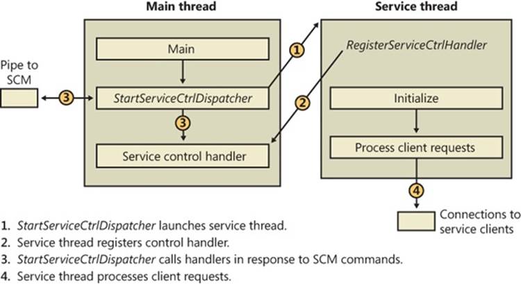
Figure 4-6. Inside a service process
Service Accounts
The security context of a service is an important consideration for service developers as well as for system administrators because it dictates what resources the process can access. Unless a service installation program or administrator specifies otherwise, most services run in the security context of the local system account (displayed sometimes as SYSTEM and other times as LocalSystem). Two other built-in accounts are the network service and local service accounts. These accounts have fewer capabilities than the local system account from a security standpoint, and any built-in Windows service that does not require the power of the local system account runs in the appropriate alternate service account. The following subsections describe the special characteristics of these accounts.
The Local System Account
The local system account is the same account in which core Windows user-mode operating system components run, including the Session Manager (%SystemRoot%\System32\Smss.exe), the Windows subsystem process (Csrss.exe), the Local Security Authority process (%SystemRoot%\System32\Lsass.exe), and the Logon process (%SystemRoot%\System32\Winlogon.exe). For more information on these latter two processes, see Chapter 6.
From a security perspective, the local system account is extremely powerful—more powerful than any local or domain account when it comes to security ability on a local system. This account has the following characteristics:
§ It is a member of the local administrators group. Table 4-8 shows the groups to which the local system account belongs. (See Chapter 6 for information on how group membership is used in object access checks.)
§ It has the right to enable virtually every privilege (even privileges not normally granted to the local administrator account, such as creating security tokens). See Table 4-9 for the list of privileges assigned to the local system account. (Chapter 6 describes the use of each privilege.)
§ Most files and registry keys grant full access to the local system account. (Even if they don’t grant full access, a process running under the local system account can exercise the take-ownership privilege to gain access.)
§ Processes running under the local system account run with the default user profile (HKU\.DEFAULT). Therefore, they can’t access configuration information stored in the user profiles of other accounts.
§ When a system is a member of a Windows domain, the local system account includes the machine security identifier (SID) for the computer on which a service process is running. Therefore, a service running in the local system account will be automatically authenticated on other machines in the same forest by using its computer account. (A forest is a grouping of domains.)
§ Unless the machine account is specifically granted access to resources (such as network shares, named pipes, and so on), a process can access network resources that allow null sessions—that is, connections that require no credentials. You can specify the shares and pipes on a particular computer that permit null sessions in the NullSessionPipes and NullSessionShares registry values under HKLM\SYSTEM\CurrentControlSet\Services\lanmanserver\parameters.
Table 4-8. Service Account Group Membership
|
Local System |
Network Service |
Local Service |
|
Everyone Authenticated Users Administrators |
Everyone Authenticated Users Users Local Network Service Service |
Everyone Authenticated Users Users Local Local Service Service |
Table 4-9. Service Account Privileges
|
Local System |
Network Service |
Local Service |
|
SeAssignPrimaryTokenPrivilege SeAuditPrivilege SeBackupPrivilege SeChangeNotifyPrivilege SeCreateGlobalPrivilege SeCreatePagefilePrivilege SeCreatePermanentPrivilege SeCreateTokenPrivilege SeDebugPrivilege SeImpersonatePrivilege SeIncreaseBasePriorityPrivilege SeIncreaseQuotaPrivilege SeLoadDriverPrivilege SeLockMemoryPrivilege SeManageVolumePrivilege SeProfileSingleProcessPrivilege SeRestorePrivilege SeSecurityPrivilege SeShutdownPrivilege SeSystemEnvironmentPrivilege SeSystemTimePrivilege SeTakeOwnershipPrivilege SeTcbPrivilege SeUndockPrivilege (client only) |
SeAssignPrimaryTokenPrivilege SeAuditPrivilege SeChangeNotifyPrivilege SeCreateGlobalPrivilege SeImpersonatePrivilege SeIncreaseQuotaPrivilege SeShutdownPrivilege SeUndockPrivilege (client only) Privileges assigned to the Everyone, Authenticated Users, and Users groups |
SeAssignPrimaryTokenPrivilege SeAuditPrivilege SeChangeNotifyPrivilege SeCreateGlobalPrivilege SeImpersonatePrivilege SeIncreaseQuotaPrivilege SeShutdownPrivilege SeUndockPrivilege (client only) Privileges assigned to the Everyone, Authenticated Users, and Users groups |
The Network Service Account
The network service account is intended for use by services that want to authenticate to other machines on the network using the computer account, as does the local system account, but do not have the need for membership in the Administrators group or the use of many of the privileges assigned to the local system account. Because the network service account does not belong to the Administrators group, services running in the network service account by default have access to far fewer registry keys and file system folders and files than the services running in the local system account. Further, the assignment of few privileges limits the scope of a compromised network service process. For example, a process running in the network service account cannot load a device driver or open arbitrary processes.
Another difference between the network service and local system accounts is that processes running in the network service account use the network service account’s profile. The registry component of the network service profile loads under HKU\S-1-5-20, and the files and directories that make up the component reside in %SystemRoot%\ServiceProfiles\NetworkService.
A service that runs in the network service account is the DNS client, which is responsible for resolving DNS names and for locating domain controllers.
The Local Service Account
The local service account is virtually identical to the network service account with the important difference that it can access only network resources that allow anonymous access. Table 4-9 shows that the network service account has the same privileges as the local service account, and Table 4-8 shows that it belongs to the same groups with the exception that it belongs to the Network Service group instead of the Local Service group. The profile used by processes running in the local service loads into HKU\S-1-5-19 and is stored in %SystemRoot%\ServiceProfiles\LocalService.
Examples of services that run in the local service account include the Remote Registry Service, which allows remote access to the local system’s registry, and the LmHosts service, which performs NetBIOS name resolution.
Running Services in Alternate Accounts
Because of the restrictions just outlined, some services need to run with the security credentials of a user account. You can configure a service to run in an alternate account when the service is created or by specifying an account and password that the service should run under with the Windows Services MMC snap-in. In the Services snap-in, right-click on a service and select Properties, click on the Log On tab, and select the This Account option, as shown in Figure 4-7.
Running with Least Privilege
Services typically are subject to an all-or-nothing model, meaning that all privileges available to the account the service process is running under are available to a service running in the process that might require only a subset of those privileges. To better conform to the principle of least privilege, in which Windows assigns services only the privileges they require, developers can specify the privileges their service requires, and the SCM creates a security token that contains only those privileges.
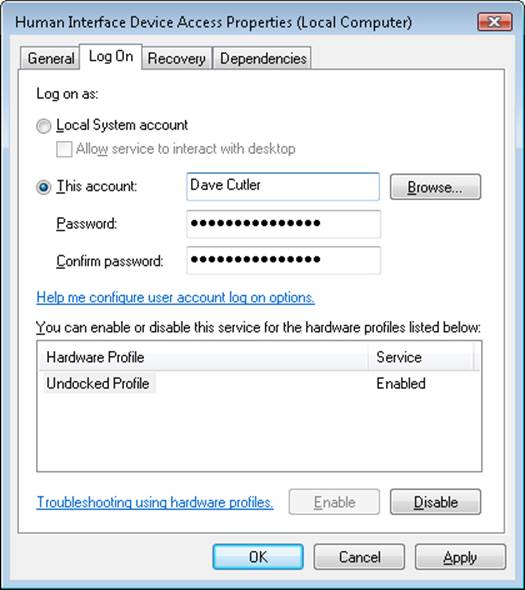
Figure 4-7. Service account settings
NOTE
The privileges a service specifies must be a subset of those that are available to the service account in which it runs.
Service developers use the ChangeServiceConfig2 API to indicate the list of privileges they desire. The API saves that information in the registry under the Parameters key for the service. When the service starts, the SCM reads the key and adds those privileges to the token of the process in which the service is running.
If there is a RequiredPrivileges value and the service is a stand-alone service (running as a dedicated process), the SCM creates a token containing only the privileges that the service needs. For services running as part of a multiservice service process (as are most services that are part of Windows) and specifying required privileges, the SCM computes the union of those privileges and combines them for the service-hosting process’ token. In other words, only the privileges not specified by any of the services that are part of that service group will be removed. In the case in which the registry value does not exist, the SCM has no choice but to assume that the service is either incompatible with least privileges or requires all privileges in order to function. In this case, the full token is created, containing all privileges, and no additional security is offered by this model. To strip almost all privileges, services can specify only the Change Notify privilege.
EXPERIMENT: VIEWING PRIVILEGES REQUIRED BY SERVICES
You can look at the privileges a service requires with the Service Control utility, Sc.exe, and the qprivs option. Additionally, Process Explorer can show you information about the security token of any service process on the system, so you can compare the information returned by Sc.exe with the privileges part of the token. The following steps show you how to do this for some of the best locked-down services on the system.
1. Use Sc.exe to take a look at the required privileges specified by Dhcp by typing the following into a command prompt:
o sc qprivs dhcp
You should see two privileges being requested: the SeCreateGlobalPrivilege and the SeChangeNotifyPrivilege.
2. Run Process Explorer, and take a look at the process list.
You should see a couple of Svchost.exe processes that are hosting the services on your machine. Process Explorer highlights these in pink.
3. Now locate the service hosting process in which the Dhcp service is running. It should be running alongside other services that are part of the LocalServiceNetworkRestricted service group, such as the Audiosrv service and Eventlog service. You can do this by hovering the mouse over each Svchost process and reading the tooltip, which contains the names of the services running inside the service host.
4. Once you’ve found the process, double-click to open the Properties dialog box and select the Security tab.
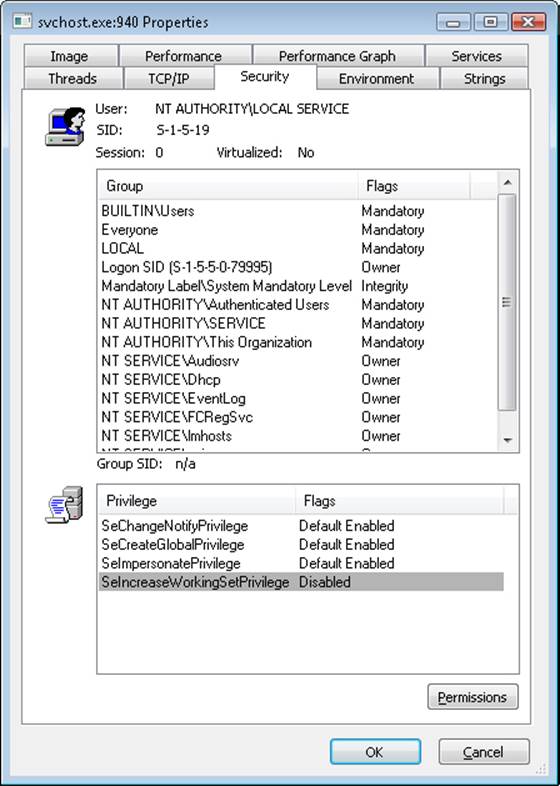
Note that although the service is running as part of the local service account, the list of privileges Windows assigned to it is much shorter than the list available to the local service account shown in Table 4-9.
Because for a service-hosting process the privileges part of the token is the union of the privileges requested by all the services running inside it, this must mean that services such as Audiosrv and Eventlog have not requested privileges other than the ones shown by Process Explorer. You can verify this by running the Sc.exe tool on those other services as well.
Service Isolation
Although restricting the privileges that a service has access to helps lessen the ability of a compromised service process to compromise other processes, it does nothing to isolate the service from resources that the account in which it is running has access to under normal conditions. As mentioned earlier, the local system account has complete access to critical system files, registry keys, and other securable objects on the system because the access control lists (ACLs) grant permissions to that account.
At times, access to some of these resources is indeed critical to a service’s operation, while other objects should be secured from the service. Previously, to avoid running in the local system account to obtain access to required resources, a service would be run under a standard user account and ACLs would be added on the system objects, which greatly increased the risk of malicious code attacking the system. Another solution was to create dedicated service accounts and set specific ACLs for each account (associated to a service), but this approach easily became an administrative hassle.
Windows now combines these two approaches into a much more manageable solution: it allows services to run in a nonprivileged account but still have access to specific privileged resources without lowering the security of those objects. In a manner similar to the second pre–Windows Vista solution, the ACLs on an object can now set permissions directly for a service, but not by requiring a dedicated account. Instead, the SCM generates a service SID to represent a service, and this SID can be used to set permissions on resources such as registry keys and files. Service SIDs are implemented in the group SIDs part of the token for any process hosting a service. They are generated by the SCM during system startup for each service that has requested one via the ChangeServiceConfig2 API. In the case of service-hosting processes (a process that contains more than one service), the process’ token will contain the service SIDs of all services that are part of the service group associated with the process, including services that are not started because there is no way to add new SIDs after a token has been created.
The usefulness of having a SID for each service extends beyond the mere ability to add ACL entries and permissions for various objects on the system as a way to have fine-grained control over their access. Our discussion initially covered the case in which certain objects on the system, accessible by a given account, must be protected from a service running within that same account. As we’ve described to this point, service SIDs prevent that problem only by requiring that Deny entries associated with the service SID be placed on every object that needs to be secured, a clearly unmanageable approach.
To avoid requiring Deny access control entries (ACEs) as a way to prevent services from having access to resources that the user account in which they run does have access, there are two types of service SIDs: the restricted service SID (SERVICE_SID_TYPE_RESTRICTED) and the unrestricted service SID (SERVICE_SID_TYPE_UNRESTRICTED), the latter being the default and the case we’ve looked at until now.
Unrestricted service SIDs are created as enabled-by-default, group owner SIDs, and the process token is also given a new ACE providing full permission to the service logon SID, which allows the service to continue communicating with the SCM. (A primary use of this would be to enable or disable service SIDs inside the process during service startup or shutdown.)
A restricted service SID, on the other hand, turns the service-hosting process’ token into a write-restricted token (see Chapter 6 for more information on tokens), which means that only objects granting explicit write access to the service SID will be writable by the service, regardless of the account it’s running as. Because of this, all services running inside that process (part of the same service group) must have the restricted SID type; otherwise, services with the restricted SID type will fail to start. Once the token becomes write-restricted, three more SIDs are added for compatibility reasons:
§ The world SID is added to allow write access to objects that are normally accessible by anyone anyway, most importantly certain DLLs in the load path.
§ The service logon SID is added to allow the service to communicate with the SCM.
§ The write-restricted SID is added to allow objects to explicitly allow any write-restricted service write access to them. For example, Event Tracing for Windows (ETW) uses this SID on its objects to allow any write-restricted service to generate events.
Figure 4-8 shows an example of a service-hosting process containing services that have been marked as having restricted service SIDs. For example, the Base Filtering Engine (BFE), which is responsible for applying Windows Firewall filtering rules, is part of this service because these rules are stored in registry keys that must be protected from malicious write access should a service be compromised. (This could allow a service exploit to disable the outgoing traffic firewall rules, enabling bidirectional communication with an attacker, for example.)
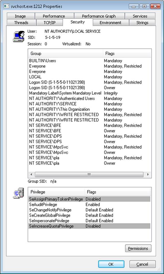
Figure 4-8. Service with restricted service SIDs
By blocking write access to objects that would otherwise be writable by the service (through inheriting the permissions of the account it is running as), restricted service SIDs solve the other side of the problem we initially presented because users do not need to do anything to prevent a service running in a privileged account from having write access to critical system files, registry keys, or other objects, limiting the attack exposure of any such service that might have been compromised.
Windows also allows for firewall rules that reference service SIDs linked to one of the three behaviors described in Table 4-10.
Table 4-10. Network Restriction Rules
|
Scenario |
Example |
Restrictions |
|
Network access blocked |
The shell hardware detection service (ShellHWDetection). |
All network communications are blocked (both incoming and outgoing). |
|
Network access statically port-restricted |
The RPC service (Rpcss) operates on port 135 (TCP and UDP). |
Network communications are restricted to specific TCP or UDP ports. |
|
Network access dynamically port-restricted |
The DNS service (Dns) listens on variable ports (UDP). |
Network communications are restricted to configurable TCP or UDP ports. |
Interactive Services and Session 0 Isolation
One restriction for services running under the local system, local service, and network service accounts that has always been present in Windows is that these services could not display (without using a special flag on the MessageBox function, discussed in a moment) dialog boxes or windows on the interactive user’s desktop. This limitation wasn’t the direct result of running under these accounts but rather a consequence of the way the Windows subsystem assigns service processes to window stations. This restriction is further enhanced by the use of sessions, in a model called Session Zero Isolation, a result of which is that services cannot directly interact with a user’s desktop.
The Windows subsystem associates every Windows process with a window station. A window station contains desktops, and desktops contain windows. Only one window station can be visible on a console and receive user mouse and keyboard input. In a Terminal Services environment, one window station per session is visible, but services all run as part of the console session. Windows names the visible window station WinSta0, and all interactive processes access WinSta0.
Unless otherwise directed, the Windows subsystem associates services running in the local system account with a nonvisible window station named Service-0x0-3e7$ that all noninteractive services share. The number in the name, 3e7, represents the logon session identifier that the Local Security Authority process (LSASS) assigns to the logon session the SCM uses for noninteractive services running in the local system account.
Services configured to run under a user account (that is, not the local system account) are run in a different nonvisible window station named with the LSASS logon identifier assigned for the service’s logon session. Figure 4-9 shows a sample display from the Sysinternals WinObj tool, viewing the object manager directory in which Windows places window station objects. Visible are the interactive window station (WinSta0) and the noninteractive system service window station (Service-0x0-3e7$).
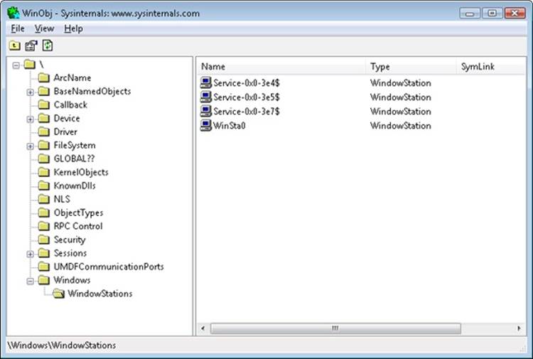
Figure 4-9. List of window stations
Regardless of whether services are running in a user account, the local system account, or the local or network service accounts, services that aren’t running on the visible window station can’t receive input from a user or display windows on the console. In fact, if a service were to pop up a normal dialog box on the window station, the service would appear hung because no user would be able to see the dialog box, which of course would prevent the user from providing keyboard or mouse input to dismiss it and allow the service to continue executing.
NOTE
In the past, it was possible to use the special MB_SERVICE_NOTIFICATION or MB_DEFAULT_DESKTOP_ONLY flags with the MessageBox API to display messages on the interactive window station even if the service was marked as noninteractive. Because of session isolation, any service using this flag will receive an immediate IDOK return value, and the message box will never be displayed.
In rare cases, a service can have a valid reason to interact with the user via dialog boxes or windows. To configure a service with the right to interact with the user, the SERVICE_INTERACTIVE_PROCESS modifier must be present in the service’s registry key’s Type parameter. (Note that services configured to run under a user account can’t be marked as interactive.) When the SCM starts a service marked as interactive, it launches the service’s process in the local system account’s security context but connects the service with WinSta0 instead of the noninteractive service window station.
Were user processes to run in the same session as services, this connection to WinSta0 would allow the service to display dialog boxes and windows on the console and enable those windows to respond to user input because they would share the window station with the interactive services. However, only processes owned by the system and Windows services run in session 0; all other logon sessions, including those of console users, run in different sessions. Any window displayed by processes in session 0 is therefore not visible to the user.
This additional boundary helps prevent shatter attacks, whereby a less privileged application sends window messages to a window visible on the same window station to exploit a bug in a more privileged process that owns the window, which permits it to execute code in the more privileged process.
To remain compatible with services that depend on user input, Windows includes a service that notifies users when a service has displayed a window. The Interactive Services Detection (UI0Detect) service looks for visible windows on the main desktop of the WinSta0 window station of session 0 and displays a notification dialog box on the console user’s desktop, allowing the user to switch to session 0 and view the service’s UI. (This is akin to connecting to a local Terminal Services session or switching users.)
NOTE
The Interactive Services Detection mechanism is purely for application compatibility, and developers are strongly recommended to move away from interactive services and use a secondary, nonprivileged helper application to communicate visually with the user. Local RPC or COM can be used between this helper application and the service for configuration purposes after UI input has been received.
The dialog box, an example of which is shown in Figure 4-10, includes the process name, the time when the UI message was displayed, and the title of the window being displayed. Once the user connects to session 0, a similar dialog box provides a portal back to the user’s session. In the figure, the service displaying a window is Microsoft Paint, which was explicitly started by the Sysinternals PsExec utility with options that caused PsExec to run Paint in session 0. You can try this yourself with the following command:
§ psexec –s –i 0 –d mspaint.exe
This tells PsExec to run Microsoft Paint as a system process (–s) running on session 0 (–i 0), and to return immediately instead of waiting for the process to finish (–d).
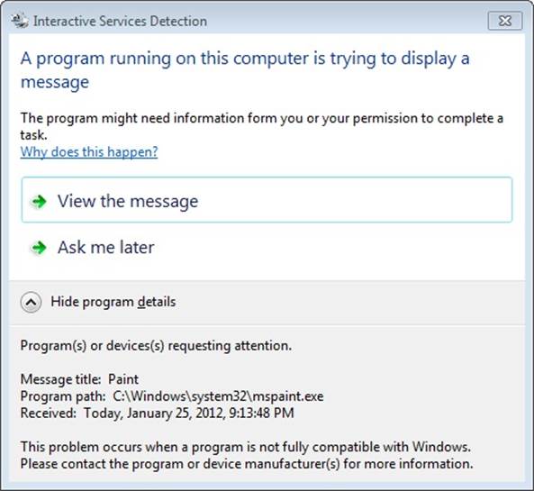
Figure 4-10. The Interactive Services Detection service at work
If you click View The Message, you can switch to the console for session 0 (and switch back again with a similar window on the console).
The Service Control Manager
The SCM’s executable file is %SystemRoot%\System32\Services.exe, and like most service processes, it runs as a Windows console program. The Wininit process starts the SCM early during the system boot. (Refer to Chapter 13 in Part 2 for details on the boot process.) The SCM’s startup function, SvcCtrlMain, orchestrates the launching of services that are configured for automatic startup.
SvcCtrlMain first creates a synchronization event named SvcctrlStartEvent_A3752DX that it initializes as nonsignaled. Only after the SCM completes steps necessary to prepare it to receive commands from SCPs does the SCM set the event to a signaled state. The function that an SCP uses to establish a dialog with the SCM is OpenSCManager. OpenSCManager prevents an SCP from trying to contact the SCM before the SCM has initialized by waiting for SvcctrlStartEvent_A3752DX to become signaled.
Next, SvcCtrlMain gets down to business and calls ScGenerateServiceDB, the function that builds the SCM’s internal service database. ScGenerateServiceDB reads and stores the contents of HKLM\SYSTEM\CurrentControlSet\Control\ServiceGroupOrder\List, a REG_MULTI_SZ value that lists the names and order of the defined service groups. A service’s registry key contains an optional Group value if that service or device driver needs to control its startup ordering with respect to services from other groups. For example, the Windows networking stack is built from the bottom up, so networking services must specify Group values that place them later in the startup sequence than networking device drivers. The SCM internally creates a group list that preserves the ordering of the groups it reads from the registry. Groups include (but are not limited to) NDIS, TDI, Primary Disk, Keyboard Port, and Keyboard Class. Add-on and third-party applications can even define their own groups and add them to the list. Microsoft Transaction Server, for example, adds a group named MS Transactions.
ScGenerateServiceDB then scans the contents of HKLM\SYSTEM\CurrentControlSet\Services, creating an entry in the service database for each key it encounters. A database entry includes all the service-related parameters defined for a service as well as fields that track the service’s status. The SCM adds entries for device drivers as well as for services because the SCM starts services and drivers marked as auto-start and detects startup failures for drivers marked boot-start and system-start. It also provides a means for applications to query the status of drivers. The I/O manager loads drivers marked boot-start and system-start before any user-mode processes execute, and therefore any drivers having these start types load before the SCM starts.
ScGenerateServiceDB reads a service’s Group value to determine its membership in a group and associates this value with the group’s entry in the group list created earlier. The function also reads and records in the database the service’s group and service dependencies by querying its DependOnGroup and DependOnService registry values. Figure 4-11 shows how the SCM organizes the service entry and group order lists. Notice that the service list is alphabetically sorted. The reason this list is sorted alphabetically is that the SCM creates the list from the Services registry key, and Windows stores registry keys alphabetically.
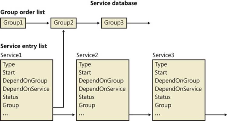
Figure 4-11. Organization of a service database
During service startup, the SCM calls on LSASS (for example, to log on a service in a non-local system account), so the SCM waits for LSASS to signal the LSA_RPC_SERVER_ACTIVE synchronization event, which it does when it finishes initializing. Wininit also starts the LSASS process, so the initialization of LSASS is concurrent with that of the SCM, and the order in which LSASS and the SCM complete initialization can vary. Then SvcCtrlMain calls ScGetBootAndSystemDriverState to scan the service database looking for boot-start and system-start device driver entries.
ScGetBootAndSystemDriverState determines whether or not a driver successfully started by looking up its name in the object manager namespace directory named \Driver. When a device driver successfully loads, the I/O manager inserts the driver’s object in the namespace under this directory, so if its name isn’t present, it hasn’t loaded. Figure 4-12 shows WinObj displaying the contents of the Driver directory. SvcCtrlMain notes the names of drivers that haven’t started and that are part of the current profile in a list named ScFailedDrivers.
Before starting the auto-start services, the SCM performs a few more steps. It creates its remote procedure call (RPC) named pipe, which is named \Pipe\Ntsvcs, and then RPC launches a thread to listen on the pipe for incoming messages from SCPs. The SCM then signals its initialization-complete event, SvcctrlStartEvent_A3752DX. Registering a console application shutdown event handler and registering with the Windows subsystem process via RegisterServiceProcess prepares the SCM for system shutdown.
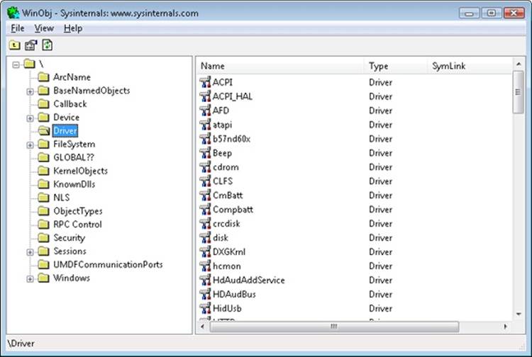
Figure 4-12. List of driver objects
NETWORK DRIVE LETTERS
In addition to its role as an interface to services, the SCM has another totally unrelated responsibility: it notifies GUI applications in a system whenever the system creates or deletes a network drive-letter connection. The SCM waits for the Multiple Provider Router (MPR) to signal a named event, \BaseNamedObjects\ScNetDrvMsg, which MPR signals whenever an application assigns a drive letter to a remote network share or deletes a remote-share drive-letter assignment. (See Chapter 7, for more information on MPR.) When MPR signals the event, the SCM calls the GetDriveType Windows function to query the list of connected network drive letters. If the list changes across the event signal, the SCM sends a Windows broadcast message of type WM_DEVICECHANGE. The SCM uses either DBT_DEVICEREMOVECOMPLETE or DBT_DEVICEARRIVAL as the message’s subtype. This message is primarily intended for Windows Explorer so that it can update any open Computer windows to show the presence or absence of a network drive letter.
Service Startup
SvcCtrlMain invokes the SCM function ScAutoStartServices to start all services that have a Start value designating auto-start (except delayed auto-start services). ScAutoStartServices also starts auto-start device drivers. To avoid confusion, you should assume that the term services means services and drivers unless indicated otherwise. The algorithm in ScAutoStartServices for starting services in the correct order proceeds in phases, whereby a phase corresponds to a group and phases proceed in the sequence defined by the group ordering stored in the HKLM\SYSTEM\CurrentControlSet\Control\ServiceGroupOrder\List registry value. The List value, shown in Figure 4-13, includes the names of groups in the order that the SCM should start them. Thus, assigning a service to a group has no effect other than to fine-tune its startup with respect to other services belonging to different groups.
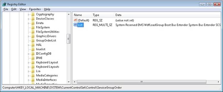
Figure 4-13. ServiceGroupOrder registry key
When a phase starts, ScAutoStartServices marks all the service entries belonging to the phase’s group for startup. Then ScAutoStartServices loops through the marked services seeing whether it can start each one. Part of this check includes seeing whether the service is marked as delayed auto-start, which causes the SCM to start it at a later stage. (Delayed auto-start services must also be ungrouped.) Another part of the check it makes consists of determining whether the service has a dependency on another group, as specified by the existence of the DependOnGroup value in the service’s registry key. If a dependency exists, the group on which the service is dependent must have already initialized, and at least one service of that group must have successfully started. If the service depends on a group that starts later than the service’s group in the group startup sequence, the SCM notes a “circular dependency” error for the service. If ScAutoStartServices is considering a Windows service or an auto-start device driver, it next checks to see whether the service depends on one or more other services, and if so, if those services have already started. Service dependencies are indicated with the DependOnService registry value in a service’s registry key. If a service depends on other services that belong to groups that come later in the ServiceGroupOrder\List, the SCM also generates a “circular dependency” error and doesn’t start the service. If the service depends on any services from the same group that haven’t yet started, the service is skipped.
When the dependencies of a service have been satisfied, ScAutoStartServices makes a final check to see whether the service is part of the current boot configuration before starting the service. When the system is booted in safe mode, the SCM ensures that the service is either identified by name or by group in the appropriate safe boot registry key. There are two safe boot keys, Minimal and Network, under HKLM\SYSTEM\CurrentControlSet\Control\SafeBoot, and the one that the SCM checks depends on what safe mode the user booted. If the user chose Safe Mode or Safe Mode With Command Prompt at the special boot menu (which you can access by pressing F8 early in the boot process), the SCM references the Minimal key; if the user chose Safe Mode With Networking, the SCM refers to Network. The existence of a string value named Option under the SafeBoot key indicates not only that the system booted in safe mode but also the type of safe mode the user selected. For more information about safe boots, see the section “Safe Mode” in Chapter 13 in Part 2.
Once the SCM decides to start a service, it calls ScStartService, which takes different steps for services than for device drivers. When ScStartService starts a Windows service, it first determines the name of the file that runs the service’s process by reading the ImagePath value from the service’s registry key. It then examines the service’s Type value, and if that value is SERVICE_WINDOWS_SHARE_PROCESS (0x20), the SCM ensures that the process the service runs in, if already started, is logged on using the same account as specified for the service being started. (This is to ensure that the service is not configured with the wrong account, such as a LocalService account, but with an image path pointing to a running Svchost, such as netsvcs, which runs as LocalSystem.) A service’s ObjectName registry value stores the user account in which the service should run. A service with no ObjectName or an ObjectName of LocalSystem runs in the local system account.
The SCM verifies that the service’s process hasn’t already been started in a different account by checking to see whether the service’s ImagePath value has an entry in an internal SCM database called the image database. If the image database doesn’t have an entry for the ImagePath value, the SCM creates one. When the SCM creates a new entry, it stores the logon account name used for the service and the data from the service’s ImagePath value. The SCM requires services to have an ImagePath value. If a service doesn’t have an ImagePath value, the SCM reports an error stating that it couldn’t find the service’s path and isn’t able to start the service. If the SCM locates an existing image database entry with matching ImagePath data, the SCM ensures that the user account information for the service it’s starting is the same as the information stored in the database entry—a process can be logged on as only one account, so the SCM reports an error when a service specifies a different account name than another service that has already started in the same process.
The SCM calls ScLogonAndStartImage to log on a service if the service’s configuration specifies and to start the service’s process. The SCM logs on services that don’t run in the System account by calling the LSASS function LogonUserEx. LogonUserEx normally requires a password, but the SCM indicates to LSASS that the password is stored as a service’s LSASS “secret” under the key HKLM\SECURITY\Policy\Secrets in the registry. (Keep in mind that the contents of SECURITY aren’t typically visible because its default security settings permit access only from the System account.) When the SCM calls LogonUserEx, it specifies a service logon as the logon type, so LSASS looks up the password in the Secrets subkey that has a name in the form _SC_<service name>.
The SCM directs LSASS to store a logon password as a secret using the LsaStorePrivateData function when an SCP configures a service’s logon information. When a logon is successful, LogonUserEx returns a handle to an access token to the caller. Windows uses access tokens to represent a user’s security context, and the SCM later associates the access token with the process that implements the service.
After a successful logon, the SCM loads the account’s profile information, if it’s not already loaded, by calling the UserEnv DLL’s (%SystemRoot%\System32\Userenv.dll) LoadUserProfile function. The value HKLM\SOFTWARE\Microsoft\Windows NT\CurrentVersion\ProfileList\<user profile key>\ProfileImagePath contains the location on disk of a registry hive that LoadUserProfile loads into the registry, making the information in the hive the HKEY_CURRENT_USER key for the service.
An interactive service must open the WinSta0 window station, but before ScLogonAndStartImage allows an interactive service to access WinSta0 it checks to see whether the value HKLM\SYSTEM\CurrentControlSet\Control\Windows\NoInteractiveServices is set. Administrators set this value to prevent services marked as interactive from displaying windows on the console. This option is desirable in unattended server environments in which no user is present to respond to the Session 0 UI Discovery notification from interactive services.
As its next step, ScLogonAndStartImage proceeds to launch the service’s process, if the process hasn’t already been started (for another service, for example). The SCM starts the process in a suspended state with the CreateProcessAsUser Windows function. The SCM next creates a named pipe through which it communicates with the service process, and it assigns the pipe the name \Pipe\Net\NtControlPipeX, where X is a number that increments each time the SCM creates a pipe. The SCM resumes the service process via the ResumeThread function and waits for the service to connect to its SCM pipe. If it exists, the registry value HKLM\SYSTEM\CurrentControlSet\Control\ServicesPipeTimeout determines the length of time that the SCM waits for a service to call StartServiceCtrlDispatcher and connect before it gives up, terminates the process, and concludes that the service failed to start. If ServicesPipeTimeout doesn’t exist, the SCM uses a default timeout of 30 seconds. The SCM uses the same timeout value for all its service communications.
When a service connects to the SCM through the pipe, the SCM sends the service a start command. If the service fails to respond positively to the start command within the timeout period, the SCM gives up and moves on to start the next service. When a service doesn’t respond to a start request, the SCM doesn’t terminate the process, as it does when a service doesn’t call StartServiceCtrlDispatcher within the timeout; instead, it notes an error in the system Event Log that indicates the service failed to start in a timely manner.
If the service the SCM starts with a call to ScStartService has a Type registry value of SERVICE_KERNEL_DRIVER or SERVICE_FILE_SYSTEM_DRIVER, the service is really a device driver, so ScStartService calls ScLoadDeviceDriver to load the driver. ScLoadDeviceDriverenables the load driver security privilege for the SCM process and then invokes the kernel service NtLoadDriver, passing in the data in the ImagePath value of the driver’s registry key. Unlike services, drivers don’t need to specify an ImagePath value, and if the value is absent, the SCM builds an image path by appending the driver’s name to the string %SystemRoot%\System32\Drivers\.
ScAutoStartServices continues looping through the services belonging to a group until all the services have either started or generated dependency errors. This looping is the SCM’s way of automatically ordering services within a group according to their DependOnService dependencies. The SCM will start the services that other services depend on in earlier loops, skipping the dependent services until subsequent loops. Note that the SCM ignores Tag values for Windows services, which you might come across in subkeys under the HKLM\SYSTEM\CurrentControlSet\Services key; the I/O manager honors Tag values to order device driver startup within a group for boot-start and system-start drivers. Once the SCM completes phases for all the groups listed in the ServiceGroupOrder\List value, it performs a phase for services belonging to groups not listed in the value and then executes a final phase for services without a group.
After handling auto-start services, the SCM calls ScInitDelayStart, which queues a delayed work item associated with a worker thread responsible for processing all the services that ScAutoStartServices skipped because they were marked delayed auto-start. This worker thread will execute after the delay. The default delay is 120 seconds, but it can be overridden by the creating an AutoStartDelay value in HKLM\SYSTEM\CurrentControlSet\Control. The SCM performs the same actions as those used during startup of nondelayed auto-start services.
DELAYED AUTO-START SERVICES
Delayed auto-start services enable Windows to cope with the growing number of services that are being started when a user logs on, bogging down the boot-up process and increasing the time before a user is able to get responsiveness from the desktop. The design of auto-start services was primarily intended for services required early in the boot process because other services depend on them, a good example being the RPC service, on which all other services depend. The other use was to allow unattended startup of a service, such as the Windows Update service. Because many auto-start services fall in this second category, marking them as delayed auto-start allows critical services to start faster and for the user’s desktop to be ready sooner when a user logs on immediately after booting. Additionally, these services run in background mode, which lowers their thread, I/O, and memory priority. Configuring a service for delayed auto-start requires calling the ChangeServiceConfig2 API. You can check the state of the flag for a service by using the qc bits option of sc.exe instead.
NOTE
If a nondelayed auto-start service has a delayed auto-start service as one of its dependencies, the delayed auto-start flag will be ignored and the service will be started immediately in order to satisfy the dependency.
When it’s finished starting all auto-start services and drivers, as well as setting up the delayed auto-start work item, the SCM signals the event \BaseNamedObjects\SC_AutoStartComplete. This event is used by the Windows Setup program to gauge startup progress during installation.
Startup Errors
If a driver or a service reports an error in response to the SCM’s startup command, the ErrorControl value of the service’s registry key determines how the SCM reacts. If the ErrorControl value is SERVICE_ERROR_IGNORE (0) or the ErrorControl value isn’t specified, the SCM simply ignores the error and continues processing service startups. If the ErrorControl value is SERVICE_ERROR_NORMAL (1), the SCM writes an event to the system Event Log that says, “The <service name> service failed to start due to the following error:”. The SCM includes the textual representation of the Windows error code that the service returned to the SCM as the reason for the startup failure in the Event Log record. Figure 4-14 shows the Event Log entry that reports a service startup error.
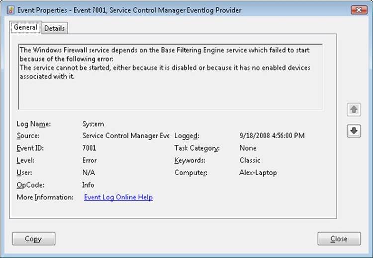
Figure 4-14. Service startup failure Event Log entry
If a service with an ErrorControl value of SERVICE_ERROR_SEVERE (2) or SERVICE_ERROR_CRITICAL (3) reports a startup error, the SCM logs a record to the Event Log and then calls the internal function ScRevertToLastKnownGood. This function switches the system’s registry configuration to a version, named last known good, with which the system last booted successfully. Then it restarts the system using the NtShutdownSystem system service, which is implemented in the executive. If the system is already booting with the last known good configuration, the system just reboots.
Accepting the Boot and Last Known Good
Besides starting services, the system charges the SCM with determining when the system’s registry configuration, HKLM\SYSTEM\CurrentControlSet, should be saved as the last known good control set. The CurrentControlSet key contains the Services key as a subkey, so CurrentControlSet includes the registry representation of the SCM database. It also contains the Control key, which stores many kernel-mode and user-mode subsystem configuration settings. By default, a successful boot consists of a successful startup of auto-start services and a successful user logon. A boot fails if the system halts because a device driver crashes the system during the boot or if an auto-start service with an ErrorControl value of SERVICE_ERROR_SEVERE or SERVICE_ERROR_CRITICAL reports a startup error.
The SCM obviously knows when it has completed a successful startup of the auto-start services, but Winlogon (%SystemRoot%\System32\Winlogon.exe) must notify it when there is a successful logon. Winlogon invokes the NotifyBootConfigStatus function when a user logs on, andNotifyBootConfigStatus sends a message to the SCM. Following the successful start of the auto-start services or the receipt of the message from NotifyBootConfigStatus (whichever comes last), the SCM calls the system function NtInitializeRegistry to save the current registry startup configuration.
Third-party software developers can supersede Winlogon’s definition of a successful logon with their own definition. For example, a system running Microsoft SQL Server might not consider a boot successful until after SQL Server is able to accept and process transactions. Developers impose their definition of a successful boot by writing a boot-verification program and installing the program by pointing to its location on disk with the value stored in the registry key HKLM\SYSTEM\CurrentControlSet\Control\BootVerificationProgram. In addition, a boot-verification program’s installation must disable Winlogon’s call to NotifyBootConfigStatus by setting HKLM\SOFTWARE\Microsoft\Windows NT\CurrentVersion\Winlogon\ReportBootOk to 0. When a boot-verification program is installed, the SCM launches it after finishing auto-start services and waits for the program’s call to NotifyBootConfigStatus before saving the last known good control set.
Windows maintains several copies of CurrentControlSet, and CurrentControlSet is really a symbolic registry link that points to one of the copies. The control sets have names in the form HKLM\SYSTEM\ControlSetnnn, where nnn is a number such as 001 or 002. The HKLM\SYSTEM\Select key contains values that identify the role of each control set. For example, if CurrentControlSet points to ControlSet001, the Current value under Select has a value of 1. The LastKnownGood value under Select contains the number of the last known good control set, which is the control set last used to boot successfully. Another value that might be on your system under the Select key is Failed, which points to the last control set for which the boot was deemed unsuccessful and aborted in favor of an attempt at booting with the last known good control set. Figure 4-15 displays a system’s control sets and Select values.
NtInitializeRegistry takes the contents of the last known good control set and synchronizes it with that of the CurrentControlSet key’s tree. If this was the system’s first successful boot, the last known good won’t exist and the system will create a new control set for it. If the last known good tree exists, the system simply updates it with differences between it and CurrentControlSet.
Last known good is helpful in situations in which a change to CurrentControlSet, such as the modification of a system performance-tuning value under HKLM\SYSTEM\Control or the addition of a service or device driver, causes the subsequent boot to fail. Users can press F8 early in the boot process to bring up a menu that lets them direct the boot to use the last known good control set, rolling the system’s registry configuration back to the way it was the last time the system booted successfully. Chapter 13 in Part 2 describes in more detail the use of last known good and other recovery mechanisms for troubleshooting system startup problems.
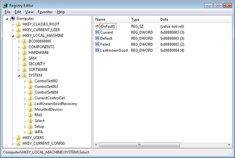
Figure 4-15. Control set selection key
Service Failures
A service can have optional FailureActions and FailureCommand values in its registry key that the SCM records during the service’s startup. The SCM registers with the system so that the system signals the SCM when a service process exits. When a service process terminates unexpectedly, the SCM determines which services ran in the process and takes the recovery steps specified by their failure-related registry values. Additionally, services are not only limited to requesting failure actions during crashes or unexpected service termination, since other problems, such as a memory leak, could also result in service failure.
If a service enters the SERVICE_STOPPED state and the error code returned to the SCM is not ERROR_SUCCESS, the SCM will check whether the service has the FailureActionsOnNonCrashFailures flag set and perform the same recovery as if the service had crashed. To use this functionality, the service must be configured via the ChangeServiceConfig2 API or the system administrator can use the Sc.exe utility with the Failureflag parameter to set FailureActionsOnNonCrashFailures to 1. The default value being 0, the SCM will continue to honor the same behavior as on earlier versions of Windows for all other services.
Actions that a service can configure for the SCM include restarting the service, running a program, and rebooting the computer. Furthermore, a service can specify the failure actions that take place the first time the service process fails, the second time, and subsequent times, and it can indicate a delay period that the SCM waits before restarting the service if the service asks to be restarted. The service failure action of the IIS Admin Service results in the SCM running the IISReset application, which performs cleanup work and then restarts the service. You can easily manage the recovery actions for a service using the Recovery tab of the service’s Properties dialog box in the Services MMC snap-in, as shown in Figure 4-16.
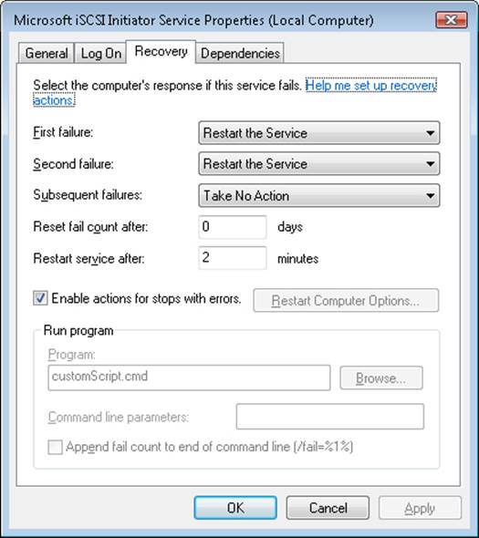
Figure 4-16. Service recovery options
Service Shutdown
When Winlogon calls the Windows ExitWindowsEx function, ExitWindowsEx sends a message to Csrss, the Windows subsystem process, to invoke Csrss’s shutdown routine. Csrss loops through the active processes and notifies them that the system is shutting down. For every system process except the SCM, Csrss waits up to the number of seconds specified by HKU\.DEFAULT\Control Panel\Desktop\WaitToKillAppTimeout (which defaults to 20 seconds) for the process to exit before moving on to the next process. When Csrss encounters the SCM process, it also notifies it that the system is shutting down but employs a timeout specific to the SCM. Csrss recognizes the SCM using the process ID Csrss saved when the SCM registered with Csrss using the RegisterServicesProcess function during system initialization. The SCM’s timeout differs from that of other processes because Csrss knows that the SCM communicates with services that need to perform cleanup when they shut down, so an administrator might need to tune only the SCM’s timeout. The SCM’s timeout value resides in the HKLM\SYSTEM\CurrentControlSet\Control\WaitToKillServiceTimeout registry value, and it defaults to 12 seconds.
The SCM’s shutdown handler is responsible for sending shutdown notifications to all the services that requested shutdown notification when they initialized with the SCM. The SCM function ScShutdownAllServices loops through the SCM services database searching for services desiring shutdown notification and sends each one a shutdown command. For each service to which it sends a shutdown command, the SCM records the value of the service’s wait hint, a value that a service also specifies when it registers with the SCM. The SCM keeps track of the largest wait hint it receives. After sending the shutdown messages, the SCM waits either until one of the services it notified of shutdown exits or until the time specified by the largest wait hint passes.
If the wait hint expires without a service exiting, the SCM determines whether one or more of the services it was waiting on to exit have sent a message to the SCM telling the SCM that the service is progressing in its shutdown process. If at least one service made progress, the SCM waits again for the duration of the wait hint. The SCM continues executing this wait loop until either all the services have exited or none of the services upon which it’s waiting has notified it of progress within the wait hint timeout period.
While the SCM is busy telling services to shut down and waiting for them to exit, Csrss waits for the SCM to exit. If Csrss’s wait ends without the SCM having exited (the WaitToKillServiceTimeout time expired), Csrss kills the SCM and continues the shutdown process. Thus, services that fail to shut down in a timely manner are killed. This logic lets the system shut down in the face of services that never complete a shutdown as a result of flawed design, but it also means that services that require more than 20 seconds will not complete their shutdown operations.
Additionally, because the shutdown order is not deterministic, services that might depend on other services to shut down first (called shutdown dependencies) have no way to report this to the SCM and might never have the chance to clean up either.
To address these needs, Windows implements preshutdown notifications and shutdown ordering to combat the problems caused by these two scenarios. Preshutdown notifications are sent, using the same mechanism as shutdown notifications, to services that have requested preshutdown notification via the SetServiceStatus API, and the SCM will wait for them to be acknowledged.
The idea behind these notifications is to flag services that might take a long time to clean up (such as database server services) and give them more time to complete their work. The SCM will send a progress query request and wait three minutes for a service to respond to this notification. If the service does not respond within this time, it will be killed during the shutdown procedure; otherwise, it can keep running as long as it needs, as long as it continues to respond to the SCM.
Services that participate in the preshutdown can also specify a shutdown order with respect to other preshutdown services. Services that depend on other services to shut down first (for example, the Group Policy service needs to wait for Windows Update to finish) can specify their shutdown dependencies in the HKLM\SYSTEM\CurrentControlSet\Control\PreshutdownOrder registry value.
Shared Service Processes
Running every service in its own process instead of having services share a process whenever possible wastes system resources. However, sharing processes means that if any of the services in the process has a bug that causes the process to exit, all the services in that process terminate.
Of the Windows built-in services, some run in their own process and some share a process with other services. For example, the LSASS process contains security-related services—such as the Security Accounts Manager (SamSs) service, the Net Logon (Netlogon) service, and the Crypto Next Generation (CNG) Key Isolation (KeyIso) service.
There is also a generic process named Service Host (SvcHost–%SystemRoot%\System32\Svchost.exe) to contain multiple services. Multiple instances of SvcHost can be running in different processes. Services that run in SvcHost processes include Telephony (TapiSrv), Remote Procedure Call (RpcSs), and Remote Access Connection Manager (RasMan). Windows implements services that run in SvcHost as DLLs and includes an ImagePath definition of the form “%SystemRoot%\System32\svchost.exe –k netsvcs” in the service’s registry key. The service’s registry key must also have a registry value named ServiceDll under a Parameters subkey that points to the service’s DLL file.
All services that share a common SvcHost process specify the same parameter (“–k netsvcs” in the example in the preceding paragraph) so that they have a single entry in the SCM’s image database. When the SCM encounters the first service that has a SvcHost ImagePath with a particular parameter during service startup, it creates a new image database entry and launches a SvcHost process with the parameter. The new SvcHost process takes the parameter and looks for a value having the same name as the parameter under HKLM\SOFTWARE\Microsoft\Windows NT\CurrentVersion\Svchost. SvcHost reads the contents of the value, interpreting it as a list of service names, and notifies the SCM that it’s hosting those services when SvcHost registers with the SCM.
When the SCM encounters a SvcHost service (by checking the service type value) during service startup with an ImagePath matching an entry it already has in the image database, it doesn’t launch a second process but instead just sends a start command for the service to the SvcHost it already started for that ImagePath value. The existing SvcHost process reads the ServiceDll parameter in the service’s registry key and loads the DLL into its process to start the service.
Table 4-11 lists all the default service groupings on Windows and some of the services that are registered for each of them.
Table 4-11. Major Service Groupings
|
Service Group |
Services |
Notes |
|
LocalService |
Network Store Interface, Windows Diagnostic Host, Windows Time, COM+ Event System, HTTP Auto-Proxy Service, Software Protection Platform UI Notification, Thread Order Service, LLDT Discovery, SSL, FDP Host, WebClient |
Services that run in the local service account and make use of the network on various ports or have no network usage at all (and hence no restrictions). |
|
LocalServiceAndNoImpersonation |
UPnP and SSDP, Smart Card, TPM, Font Cache, Function Discovery, AppID, qWAVE, Windows Connect Now, Media Center Extender, Adaptive Brightness |
Services that run in the local service account and make use of the network on a fixed set of ports. Services run with a write-restricted token. |
|
LocalServiceNetworkRestricted |
DHCP, Event Logger, Windows Audio, NetBIOS, Security Center, Parental Controls, HomeGroup Provider |
Services that run in the local service account and make use of the network on a fixed set of ports. |
|
LocalServiceNoNetwork |
Diagnostic Policy Engine, Base Filtering Engine, Performance Logging and Alerts, Windows Firewall, WWAN AutoConfig |
Services that run in the local service account but make no use of the network at all. Services run with a write-restricted token. |
|
LocalSystemNetworkRestricted |
DWM, WDI System Host, Network Connections, Distributed Link Tracking, Windows Audio Endpoint, Wired/WLAN AutoConfig, Pnp-X, HID Access, User-Mode Driver Framework Service, Superfetch, Portable Device Enumerator, HomeGroup Listener, Tablet Input, Program Compatibility, Offline Files |
Services that run in the local system account and make use of the network on a fixed set of ports. |
|
NetworkService |
Cryptographic Services, DHCP Client, Terminal Services, WorkStation, Network Access Protection, NLA, DNS Client, Telephony, Windows Event Collector, WinRM |
Services that run in the network service account and make use of the network on various ports (or have no enforced network restrictions). |
|
NetworkServiceAndNoImpersonation |
KTM for DTC |
Services that run in the network service account and make use of the network on a fixed set of ports. Services run with a write-restricted token. |
|
NetworkServiceNetworkRestricted |
IPSec Policy Agent |
Services that run in the network service account and make use of the network on a fixed set of ports. |
EXPERIMENT: VIEWING SERVICES RUNNING INSIDE PROCESSES
The Process Explorer utility shows detailed information about the services running within processes. Run Process Explorer, and view the Services tab in the Process Properties dialog box for the following processes: Services.exe, Lsass.exe, and Svchost.exe. Several instances of SvcHost will be running on your system, and you can see the account in which each is running by adding the Username column to the Process Explorer display or by looking at the Username field on the Image tab of a process’ Process Properties dialog box. The following screen shows the list of services running within a SvcHost executing in the local service account:
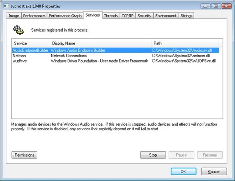
The information displayed includes the service’s name, display name, and description, if it has one, which Process Explorer shows beneath the service list when you select a service. Additionally, the path of the DLL containing the service is shown. This information is useful for mapping thread start addresses (shown on the Threads tab) to their respective services, which can help in cases of service-related problems such as troubleshooting high CPU usage.
You can also use the tlist.exe tool from the Debugging Tools for Windows or Tasklist, which ships with Windows, to view the list of services running within processes from a command prompt. The syntax to see services with Tlist is:
tlist /s
The syntax for tasklist is:
tasklist /svc
Note that these utilities do not show service display names or descriptions, only service names.
Service Tags
One of the disadvantages of using service-hosting processes is that accounting for CPU time and usage, as well as for the usage of resources, by a specific service is much harder because each service is sharing the memory address space, handle table, and per-process CPU accounting numbers with the other services that are part of the same service group. Although there is always a thread inside the service-hosting process that belongs to a certain service, this association might not always be easy to make. For example, the service might be using worker threads to perform its operation, or perhaps the start address and stack of the thread do not reveal the service’s DLL name, making it hard to figure out what kind of work a thread might exactly be doing and to which service it might belong.
Windows implements a service attribute called the service tag, which the SCM generates by calling ScGenerateServiceTag when a service is created or when the service database is generated during system boot. The attribute is simply an index identifying the service. The service tag is stored in the SubProcessTag field of the thread environment block (TEB) of each thread (see Chapter 5, for more information on the TEB) and is propagated across all threads that a main service thread creates (except threads created indirectly by thread-pool APIs).
Although the service tag is kept internal to the SCM, several Windows utilities, like Netstat.exe (a utility you can use for displaying which programs have opened which ports on the network), use undocumented APIs to query service tags and map them to service names. Because the TCP/IP stack saves the service tag of the threads that create TCP/IP end points, when you run Netstat with the –b parameter, Netstat can report the service name for end points created by services. Another tool you can use to look at service tags is ScTagQuery from Winsider Seminars & Solutions Inc. (www.winsiderss.com/tools/sctagquery/sctagquery.htm). It can query the SCM for the mappings of every service tag and display them either systemwide or per-process. It can also show you to which services all the threads inside a service-hosting process belong. (This is conditional on those threads having a proper service tag associated with them.) This way, if you have a runaway service consuming lots of CPU time, you can identify the culprit service in case the thread start address or stack does not have an obvious service DLL associated with it.
Unified Background Process Manager
Various Windows components have traditionally been in charge of managing hosted or background tasks as the operating system has increased in complexity in features, from the Service Control Manager described earlier to the Task Scheduler, the DCOM Server Launcher, and the WMI Provider—all of which are also responsible for the execution of out-of-process, hosted code. Today, Windows implements a Unified Background Process Manager (UBPM), which handles (at least, for now) two of these mechanisms—the SCM and Task Scheduler—providing the ability for these components to access UBPM functionality.
UBPM is implemented in Services.exe, in the same location as the SCM, but as a separate library providing its own interface over RPC (similarly to how the Plug and Play Manager also runs in Services.exe but is a separate component). It provides access to that interface through a public export DLL, Ubpm.dll, which is exposed to third-party service developers through new Trigger APIs that have been added to the SCM. The SCM then loads a custom SCM Extension DLL (Scext.dll), which calls into Ubpm.dll. This layer of indirection is needed for MinWin support, where Scext.dll is not loaded and the SCM provides only minimal functionality. Figure 4-17 describes this architecture.
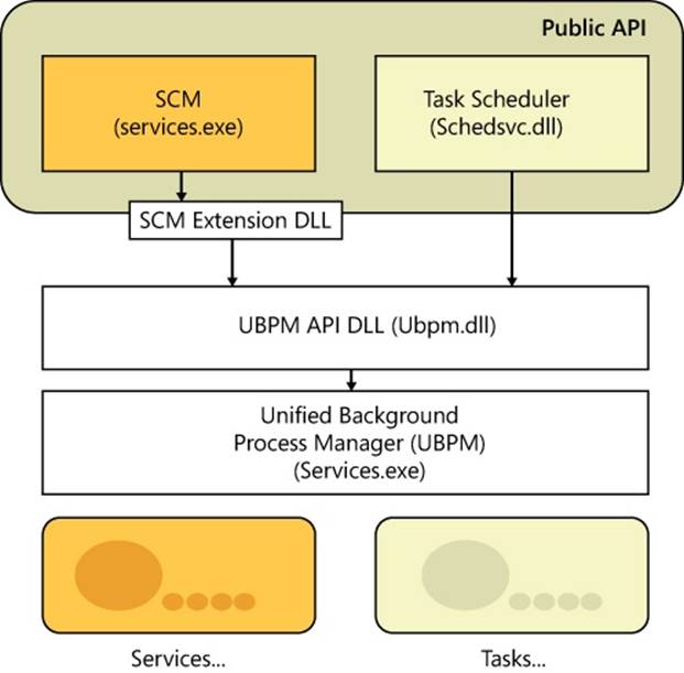
Figure 4-17. Overall UBPM architecture
Initialization
UBPM is initialized by the SCM when its UbpmInitialize export is called by ScExtInitializeTerminateUbpm in the SCM Extension DLL. As such, it is implemented as a DLL running within the context of the SCM, not as its own separate process.
UBPM first begins initialization by setting up its internal utility library. By leveraging many of the improvements in newer versions of Windows, UBPM uses a thread pool to process the many incoming events we will later see, which allows it to scale from having a single worker thread to having up to 1000 (based on a maximum processing of 10,000 consumers).
Next, UBPM initializes its internal tracing support, which can be configured in the HKLM\Software\Microsoft\Windows NT\CurrentVersion\Tracing\UBPM\Regular key using the Flags value. This is useful for debugging and monitoring the behavior of the UBPM using the WPP tracing mechanism described in the Windows Driver Kit.
Following that, the event manager is set up, which will be used by later components of UBPM to report internal event states. The event manager registers a TASKSCHED GUID on which ETW events can be consumed, and it logs its state to a TaskScheduler.log file.
The next step, critical to UBPM, is to initialize its own real-time ETW consumer, which is the central mechanism used by UBPM to perform its job, as almost all the data it receives comes over as ETW events. UBPM starts an ETW real-time session in secure mode, meaning that it will be the only process capable of receiving its events, and it names its session UBPM. It also enables the first built-in provider (owned by the kernel) in order to receive notifications related to time changes.
It then associates an event callback—UbpmpEventCallback—with incoming events and creates a consumer thread, UbpmpConsumeEvents, that waits for the SCM’s event used to signify that auto-start events have completed (which was named previously). Once this happens, the consumer thread calls ProcessTrace, which calls into ETW and blocks the thread until the ETW trace is completed (normally, only once UBPM exists). The event callback, on the other hand, consumes each ETW event as it arrives and processes it according to the algorithm we’ll see in the next section.
ETW automatically replays any events that were missed before ProcessTrace was called, which means that kernel events during the boot will all be incoming at once and processed appropriately. UBPM also waits on the SCM’s auto-start event, which makes sure that when these events do come in, there will at least have been a couple of services that registered for them; otherwise, starting the trace too early will result in events with no registered consumers, which will cause them to be lost.
Finally, UBPM sets up a local RPC interface to TaskHost—the second component of UBPM, which we’ll describe later—and it also sets up its own local RPC interface, which exposes the APIs that allows services to use UBPM functionality (such as registering trigger providers, generating triggers and notifications, and so forth). These APIs are implemented in the Ubpm.dll library and use RPC to communicate to the RPC interface in the UBPM code of Services.exe.
When UBPM exits, the opposite actions in the reverse order are performed to reset the system to its previous state.
UBPM API
UBPM enables the following mechanisms to be used by having services use the UBPM API:
§ Registering and unregistering a trigger provider, as well as opening and closing a handle to one
§ Generating a notification or a trigger
§ Setting and querying the configuration of a trigger provider
§ Sending a control command to a trigger provider
Provider Registration
Providers are registered through the SCM Extension DLL, which uses the ScExtpRegisterProvider function that is used by ScExtGenerateNotification. This opens a handle to UBPM and calls the UbpmRegisterTriggerProvider API. When a service registers a provider, it must define a unique name and GUID for the provider, as well as the necessary flags to define the provider (for example, by using the ETW provider flag). Additionally, providers can also have a friendly name as well as a description. Once registration is completed, the provider is inserted into UBPM’s provider list, the total count of providers is incremented, and, if this is an ETW provider that’s not being started with the disabled flag, the provider’s GUID is enabled in the real-time ETW trace that UBPM activated upon initialization. A provider block is created containing all the provider’s information that was captured from the registration.
Now that a provider is registered, the open and close API can be used to increment the reference count to the provider and return its provider block. Furthermore, if the provider was not registered in a disabled state, and this is the first reference to it, its GUID is enabled in the real-time ETW trace.
Similarly, unregistering a provider will disable its GUID and unlink it from the provider list, and as soon as all references are closed, the provider block will be deleted.
EXPERIMENT: VIEWING UBPM TRIGGER PROVIDERS
You can use the Performance Monitor to see UBPM actively monitoring all the ETW providers that have registered with it. Follow these instructions to do so:
1. Open the Performance Monitor by clicking on the Start button, and then choosing Run.
2. Type perfmon, and click OK.
3. When Performance Monitor launches, expand Data Collector Sets on the left sidebar by clicking the arrow.
4. Choose Event Trace Sessions from the list, and then double click on the UBPM entry.
The following screen shot displays the UBPM trigger providers on the author’s machine. You should see a similar display.
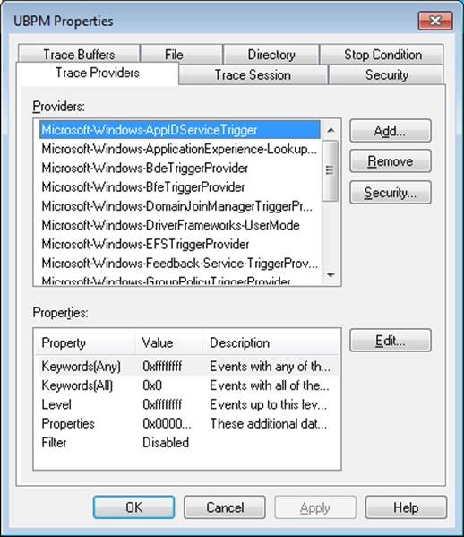
As you can see from the large list, dozens of providers are registered, each of them capable of generating individual events. For example, the BfeTriggerProvider handles Firewall events. In a later experiment, you will see a consumer of such an event.
Consumer Registration
Service consumer registration is initially exposed by the ScExtRegisterTriggerConsumer callback that the SCM Extension DLL provides. Its job is to receive all the SCM-formatted trigger information (which service developers provide according to the MSDN API documentation, “Service Trigger Events” available on MSDN) and convert that information into the raw data structures that UBPM internally uses. Once all the processing is finished, the SCM Extension DLL packages the trigger and associates it with two actions: UBPM Start Service and UBPM Stop Service.
The Scheduled Tasks service, which also leverages UBPM, provides similar functionality through an internal UBPM Singleton Class, which calls into Ubpm.dll. It allows its internal RegisterTask API to also register for trigger consumption, and it does similar processing of its input data, with the difference being that it uses the UBPM Start EXE action. Next, to actually perform the registration, both open a handle to UBPM, check if the consumer is already registered (changes to existing consumers are not allowed), and finally register the provider through theUbpmRegisterTriggerConsumer API.
Trigger consumer registration is done by UbpmTriggerProviderRegister, which validates the request, adds the provider’s GUID into the list of providers, and toggles it to enable the ETW trace to now receive events about this provider as well.
EXPERIMENT: VIEWING WHICH SERVICES REACT TO WHICH TRIGGERS
Certain Windows services are already preconfigured to consume the appropriate triggers to prevent them from staying resident even when they’re not needed, such as the Windows Time Service, the Tablet Input Service, and the Computer Browser service. The sc command lets you query information about a service’s triggers with the qtriggerinfo option.
1. Open a command prompt.
2. Type the following to see the triggers for the Windows Time Service:
3. sc qtriggerinfo w32time
4.
5. [SC] QueryServiceConfig2 SUCCESS
6. SERVICE_NAME: w32time
7.
8. START SERVICE
9. DOMAIN JOINED STATUS : 1ce20aba-9851-4421-9430-1ddeb766e809
10.[DOMAIN JOINED]
11. STOP SERVICE
12. DOMAIN JOINED STATUS : ddaf516e-58c2-4866-9574-c3b615d42ea1
[NOT DOMAIN JOINED]
13. Now look at the Tablet Input Service:
14.sc qtriggerinfo tabletinputservice
15.[SC] QueryServiceConfig2 SUCCESS
16.SERVICE_NAME: tabletinputservice
17.
18. START SERVICE
19. DEVICE INTERFACE ARRIVAL : 4d1e55b2-f16f-11cf-88cb-001111000030
20.[INTERFACE CLASS GUID]
21. DATA : HID_DEVICE_UP:000D_U:0001
22. DATA : HID_DEVICE_UP:000D_U:0002
23. DATA : HID_DEVICE_UP:000D_U:0003
DATA : HID_DEVICE_UP:000D_U:0004
24. Finally, here is the Computer Browser Service:
25.sc qtriggerinfo browser
26.[SC] QueryServiceConfig2 SUCCESS
27.
28.SERVICE_NAME: browser
29.
30. START SERVICE
31. FIREWALL PORT EVENT : b7569e07-8421-4ee0-ad10-86915afdad09
32.[PORT OPEN]
33. DATA : 139;TCP;System;
34. DATA : 137;UDP;System;
35. DATA : 138;UDP;System;
36. STOP SERVICE
37. FIREWALL PORT EVENT : a144ed38-8e12-4de4-9d96-e64740b1a524
38.[PORT CLOSE]
39. DATA : 139;TCP;System;
40. DATA : 137;UDP;System;
DATA : 138;UDP;System;
In these three cases, note how the Windows Time Service is waiting for domain join/exit in order to decide whether or not it should run, while the Tablet Input Service is waiting for a device with the HID Class ID matching Tablet Device. Finally, the Computer Browser Service will run only if the firewall policy allows access on ports 137, 138, and 139, which are SMB network ports that the browser needs.
Task Host
TaskHost receives commands from UBPM living in the SCM. At initialization time, it opens the local RPC interface that was created by UBPM during its initialization and loops forever, waiting for commands to come through the channel. Four commands are currently supported, which are sent over the TaskHostSendResponseReceiveCommand RPC API:
§ Stopping the host
§ Starting a task
§ Stopping a task
§ Terminating a task
Additionally, hosted tasks are supplied with a TaskHostReportTaskStatus RPC API, which enables them to notify UBPM of their current execution state whenever they call UbpmReportTaskStatus.
All task-based commands are actually internally implemented by a generic COM Task library, and they essentially result in the creation and destruction of COM components.
Service Control Programs
Service control programs are standard Windows applications that use SCM service management functions, including CreateService, OpenService, StartService, ControlService, QueryServiceStatus, and DeleteService. To use the SCM functions, an SCP must first open a communications channel to the SCM by calling the OpenSCManager function. At the time of the open call, the SCP must specify what types of actions it wants to perform. For example, if an SCP simply wants to enumerate and display the services present in the SCM’s database, it requests enumerate-service access in its call to OpenSCManager. During its initialization, the SCM creates an internal object that represents the SCM database and uses the Windows security functions to protect the object with a security descriptor that specifies what accounts can open the object with what access permissions. For example, the security descriptor indicates that the Authenticated Users group can open the SCM object with enumerate-service access. However, only administrators can open the object with the access required to create or delete a service.
As it does for the SCM database, the SCM implements security for services themselves. When an SCP creates a service by using the CreateService function, it specifies a security descriptor that the SCM associates internally with the service’s entry in the service database. The SCM stores the security descriptor in the service’s registry key as the Security value, and it reads that value when it scans the registry’s Services key during initialization so that the security settings persist across reboots. In the same way that an SCP must specify what types of access it wants to the SCM database in its call to OpenSCManager, an SCP must tell the SCM what access it wants to a service in a call to OpenService. Accesses that an SCP can request include the ability to query a service’s status and to configure, stop, and start a service.
The SCP you’re probably most familiar with is the Services MMC snap-in that’s included in Windows, which resides in %SystemRoot%\System32\Filemgmt.dll. Windows also includes Sc.exe (Service Controller tool), a command-line service control program that we’ve mentioned multiple times.
SCPs sometimes layer service policy on top of what the SCM implements. A good example is the timeout that the Services MMC snap-in implements when a service is started manually. The snap-in presents a progress bar that represents the progress of a service’s startup. Services indirectly interact with SCPs by setting their configuration status to reflect their progress as they respond to SCM commands such as the start command. SCPs query the status with the QueryServiceStatus function. They can tell when a service actively updates the status versus when a service appears to be hung, and the SCM can take appropriate actions in notifying a user about what the service is doing.
Windows Management Instrumentation
Windows Management Instrumentation (WMI) is an implementation of Web-Based Enterprise Management (WBEM), a standard that the Distributed Management Task Force (DMTF—an industry consortium) defines. The WBEM standard encompasses the design of an extensible enterprise data-collection and data-management facility that has the flexibility and extensibility required to manage local and remote systems that comprise arbitrary components.
WMI Architecture
WMI consists of four main components, as shown in Figure 4-18: management applications, WMI infrastructure, providers, and managed objects. Management applications are Windows applications that access and display or process data about managed objects. A simple example of a management application is a performance tool replacement that relies on WMI rather than the Performance API to obtain performance information. A more complex example is an enterprise-management tool that lets administrators perform automated inventories of the software and hardware configuration of every computer in their enterprise.
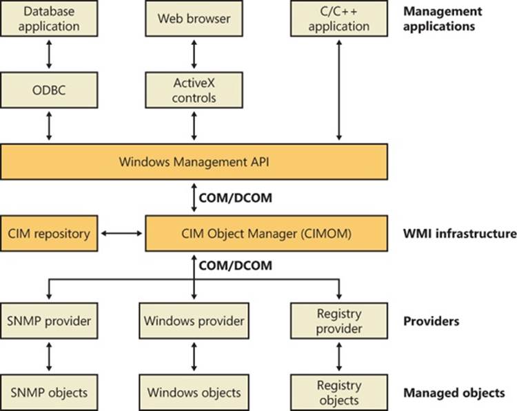
Figure 4-18. WMI architecture
Developers typically must target management applications to collect data from and manage specific objects. An object might represent one component, such as a network adapter device, or a collection of components, such as a computer. (The computer object might contain the network adapter object.) Providers need to define and export the representation of the objects that management applications are interested in. For example, the vendor of a network adapter might want to add adapter-specific properties to the network adapter WMI support that Windows includes, querying and setting the adapter’s state and behavior as the management applications direct. In some cases (for example, for device drivers), Microsoft supplies a provider that has its own API to help developers leverage the provider’s implementation for their own managed objects with minimal coding effort.
The WMI infrastructure, the heart of which is the Common Information Model (CIM) Object Manager (CIMOM), is the glue that binds management applications and providers. (CIM is described later in this chapter.) The infrastructure also serves as the object-class store and, in many cases, as the storage manager for persistent object properties. WMI implements the store, or repository, as an on-disk database named the CIMOM Object Repository. As part of its infrastructure, WMI supports several APIs through which management applications access object data and providers supply data and class definitions.
Windows programs and scripts (such as Windows PowerShell) use the WMI COM API, the primary management API, to directly interact with WMI. Other APIs layer on top of the COM API and include an Open Database Connectivity (ODBC) adapter for the Microsoft Access database application. A database developer uses the WMI ODBC adapter to embed references to object data in the developer’s database. Then the developer can easily generate reports with database queries that contain WMI-based data. WMI ActiveX controls support another layered API. Web developers use the ActiveX controls to construct web-based interfaces to WMI data. Another management API is the WMI scripting API, for use in script-based applications and Microsoft Visual Basic programs. WMI scripting support exists for all Microsoft programming language technologies.
As they are for management applications, WMI COM interfaces constitute the primary API for providers. However, unlike management applications, which are COM clients, providers are COM or Distributed COM (DCOM) servers (that is, the providers implement COM objects that WMI interacts with). Possible embodiments of a WMI provider include DLLs that load into WMI’s manager process or stand-alone Windows applications or Windows services. Microsoft includes a number of built-in providers that present data from well-known sources, such as the Performance API, the registry, the Event Manager, Active Directory, SNMP, and modern device drivers. The WMI SDK lets developers develop third-party WMI providers.
Providers
At the core of WBEM is the DMTF-designed CIM specification. The CIM specifies how management systems represent, from a systems management perspective, anything from a computer to an application or device on a computer. Provider developers use the CIM to represent the components that make up the parts of an application for which the developers want to enable management. Developers use the Managed Object Format (MOF) language to implement a CIM representation.
In addition to defining classes that represent objects, a provider must interface WMI to the objects. WMI classifies providers according to the interface features the providers supply. Table 4-12 lists WMI provider classifications. Note that a provider can implement one or more features; therefore, a provider can be, for example, both a class and an event provider. To clarify the feature definitions in Table 4-12, let’s look at a provider that implements several of those features. The Event Log provider supports several objects, including an Event Log Computer, an Event Log Record, and an Event Log File. The Event Log is an Instance provider because it can define multiple instances for several of its classes. One class for which the Event Log provider defines multiple instances is the Event Log File class (Win32_NTEventlogFile); the Event Log provider defines an instance of this class for each of the system’s event logs (that is, System Event Log, Application Event Log, and Security Event Log).
Table 4-12. Provider Classifications
|
Classification |
Description |
|
Class |
Can supply, modify, delete, and enumerate a provider-specific class. It can also support query processing. Active Directory is a rare example of a service that is a class provider. |
|
Instance |
Can supply, modify, delete, and enumerate instances of system and provider-specific classes. An instance represents a managed object. It can also support query processing. |
|
Property |
Can supply and modify individual object property values. |
|
Method |
Supplies methods for a provider-specific class. |
|
Event |
Generates event notifications. |
|
Event consumer |
Maps a physical consumer to a logical consumer to support event notification. |
The Event Log provider defines the instance data and lets management applications enumerate the records. To let management applications use WMI to back up and restore the Event Log files, the Event Log provider implements backup and restore methods for Event Log File objects. Doing so makes the Event Log provider a Method provider. Finally, a management application can register to receive notification whenever a new record writes to one of the Event Logs. Thus, the Event Log provider serves as an Event provider when it uses WMI event notification to tell WMI that Event Log records have arrived.
The Common Information Model and the Managed Object Format Language
The CIM follows in the steps of object-oriented languages such as C++ and C#, in which a modeler designs representations as classes. Working with classes lets developers use the powerful modeling techniques of inheritance and composition. Subclasses can inherit the attributes of a parent class, and they can add their own characteristics and override the characteristics they inherit from the parent class. A class that inherits properties from another class derives from that class. Classes also compose: a developer can build a class that includes other classes.
The DMTF provides multiple classes as part of the WBEM standard. These classes are CIM’s basic language and represent objects that apply to all areas of management. The classes are part of the CIM core model. An example of a core class is CIM_ManagedSystemElement. This class contains a few basic properties that identify physical components such as hardware devices and logical components such as processes and files. The properties include a caption, description, installation date, and status. Thus, the CIM_LogicalElement and CIM_PhysicalElement classes inherit the attributes of the CIM_ManagedSystemElement class. These two classes are also part of the CIM core model. The WBEM standard calls these classes abstract classes because they exist solely as classes that other classes inherit (that is, no object instances of an abstract class exist). You can therefore think of abstract classes as templates that define properties for use in other classes.
A second category of classes represents objects that are specific to management areas but independent of a particular implementation. These classes constitute the common model and are considered an extension of the core model. An example of a common-model class is the CIM_FileSystem class, which inherits the attributes of CIM_LogicalElement. Because virtually every operating system—including Windows, Linux, and other varieties of UNIX—rely on file-system-based structured storage, the CIM_FileSystem class is an appropriate constituent of the common model.
The final class category, the extended model, comprises technology-specific additions to the common model. Windows defines a large set of these classes to represent objects specific to the Windows environment. Because all operating systems store data in files, the CIM common model includes the CIM_LogicalFile class. The CIM_DataFile class inherits the CIM_LogicalFile class, and Windows adds the Win32_PageFile and Win32_ShortcutFile file classes for those Windows file types.
The Event Log provider makes extensive use of inheritance. Figure 4-19 shows a view of the WMI CIM Studio, a class browser that ships with the WMI Administrative Tools that you can obtain from the Microsoft download center at the Microsoft website. You can see where the Event Log provider relies on inheritance in the provider’s Win32_NTEventlogFile class, which derives from CIM_DataFile. Event Log files are data files that have additional Event Log–specific attributes such as a log file name (LogfileName) and a count of the number of records that the file contains (NumberOfRecords). The tree that the class browser shows reveals that Win32_NTEventlogFile is based on several levels of inheritance, in which CIM_DataFile derives from CIM_LogicalFile, which derives from CIM_LogicalElement, and CIM_LogicalElement derives from CIM_ManagedSystemElement.
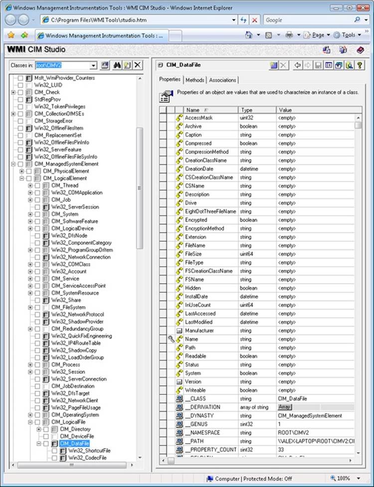
Figure 4-19. WMI CIM Studio
As stated earlier, WMI provider developers write their classes in the MOF language. The following output shows the definition of the Event Log provider’s Win32_NTEventlogFile, which is selected in Figure 4-19. Notice the correlation between the properties that the right panel inFigure 4-19 lists and those properties’ definitions in the MOF file that follows. CIM Studio uses yellow arrows to tag the properties that a class inherits. Thus, you don’t see those properties specified in Win32_NTEventlogFile’s definition.
dynamic: ToInstance, provider("MS_NT_EVENTLOG_PROVIDER"), Locale(1033), UUID("{8502C57B-5FBB-11D2-AAC1-006008C78BC7}")]
class Win32_NTEventlogFile : CIM_DataFile
{
[read] string LogfileName;
[read, write] uint32 MaxFileSize;
[read] uint32 NumberOfRecords;
[read, volatile, ValueMap{"0", "1..365", "4294967295"}] string OverWritePolicy;
[read, write, Units("Days"), Range("0-365 | 4294967295")] uint32 OverwriteOutDated;
[read] string Sources[];
[implemented, Privileges{"SeSecurityPrivilege", "SeBackupPrivilege"}] uint32 ClearEventlog([in]
string ArchiveFileName);
[implemented, Privileges{"SeSecurityPrivilege", "SeBackupPrivilege"}] uint32 BackupEventlog([in]
string ArchiveFileName);
};
One term worth reviewing is dynamic, which is a descriptive designator for the Win32_NTEventlogFile class that the MOF file in the preceding output shows. “Dynamic” means that the WMI infrastructure asks the WMI provider for the values of properties associated with an object of that class whenever a management application queries the object’s properties. A static class is one in the WMI repository; the WMI infrastructure refers to the repository to obtain the values instead of asking a provider for the values. Because updating the repository is a relatively expensive operation, dynamic providers are more efficient for objects that have properties that change frequently.
EXPERIMENT: VIEWING THE MOF DEFINITIONS OF WMI CLASSES
You can view the MOF definition for any WMI class by using the WbemTest tool that comes with Windows. In this experiment, we’ll look at the MOF definition for the Win32_NTEventLogFile class:
1. Run Wbemtest from the Start menu’s Run dialog box.
2. Click the Connect button, change the Namespace to root\cimv2, and connect.
3. Click the Enum Classes button, select the Recursive option button, and then click OK.
4. Find Win32_NTEventLogFile in the list of classes, and then double-click it to see its class properties.
5. Click the Show MOF button to open a window that displays the MOF text.
After constructing classes in MOF, WMI developers can supply the class definitions to WMI in several ways. WDM driver developers compile a MOF file into a binary MOF (BMF) file—a more compact binary representation than a MOF file—and can choose to dynamically give the BMF files to the WDM infrastructure or to statically include it in their binary. Another way is for the provider to compile the MOF and use WMI COM APIs to give the definitions to the WMI infrastructure. Finally, a provider can use the MOF Compiler (Mofcomp.exe) tool to give the WMI infrastructure a classes-compiled representation directly.
The WMI Namespace
Classes define the properties of objects, and objects are class instances on a system. WMI uses a namespace that contains several subnamespaces that WMI arranges hierarchically to organize objects. A management application must connect to a namespace before the application can access objects within the namespace.
WMI names the namespace root directory root. All WMI installations have four predefined namespaces that reside beneath root: CIMV2, Default, Security, and WMI. Some of these namespaces have other namespaces within them. For example, CIMV2 includes the Applications and ms_409 namespaces as subnamespaces. Providers sometimes define their own namespaces; you can see the WMI namespace (which the Windows device driver WMI provider defines) beneath root in Windows.
EXPERIMENT: VIEWING WMI NAMESPACES
You can see what namespaces are defined on a system with WMI CIM Studio. WMI CIM Studio presents a connection dialog box when you run it that includes a namespace browsing button to the right of the namespace edit box. Opening the browser and selecting a namespace has WMI CIM Studio connect to that namespace. Windows defines over a dozen namespaces beneath root, some of which are visible here:
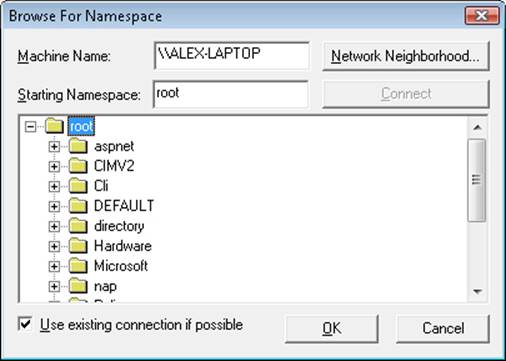
Unlike a file system namespace, which comprises a hierarchy of directories and files, a WMI namespace is only one level deep. Instead of using names as a file system does, WMI uses object properties that it defines as keys to identify the objects. Management applications specify class names with key names to locate specific objects within a namespace. Thus, each instance of a class must be uniquely identifiable by its key values. For example, the Event Log provider uses the Win32_NTLogEvent class to represent records in an Event Log. This class has two keys: Logfile, a string; and RecordNumber, an unsigned integer. A management application that queries WMI for instances of Event Log records obtains them from the provider key pairs that identify records. The application refers to a record using the syntax that you see in this sample object path name:
\\DARYL\root\CIMV2:Win32_NTLogEvent.Logfile="Application",
RecordNumber="1"
The first component in the name (\\DARYL) identifies the computer on which the object is located, and the second component (\root\CIMV2) is the namespace in which the object resides. The class name follows the colon, and key names and their associated values follow the period. A comma separates the key values.
WMI provides interfaces that let applications enumerate all the objects in a particular class or to make queries that return instances of a class that match a query criterion.
Class Association
Many object types are related to one another in some way. For example, a computer object has a processor, software, an operating system, active processes, and so on. WMI lets providers construct an association class to represent a logical connection between two different classes. Association classes associate one class with another, so the classes have only two properties: a class name and the Ref modifier. The following output shows an association in which the Event Log provider’s MOF file associates the Win32_NTLogEvent class with the Win32_ComputerSystem class. Given an object, a management application can query associated objects. In this way, a provider defines a hierarchy of objects.
[dynamic: ToInstance, provider("MS_NT_EVENTLOG_PROVIDER"): ToInstance, EnumPrivileges{"Se
SecurityPrivilege"}:
ToSubClass, Locale(1033): ToInstance, UUID("{8502C57F-5FBB-11D2-AAC1-006008C78BC7}"):
ToInstance, Association: DisableOverride ToInstance ToSubClass]
class Win32_NTLogEventComputer
{
[key, read: ToSubClass] Win32_ComputerSystem ref Computer;
[key, read: ToSubClass] Win32_NTLogEvent ref Record;
};
Figure 4-20 shows the WMI Object Browser (another tool that the WMI Administrative Tools includes) displaying the contents of the CIMV2 namespace. Windows system components typically place their objects within the CIMV2 namespace. The Object Browser first locates the Win32_ComputerSystem object instance ALEX-LAPTOP, which is the object that represents the computer. Then the Object Browser obtains the objects associated with Win32_ComputerSystem and displays them beneath ALEX-LAPTOP. The Object Browser user interface displays association objects with a double-arrow folder icon. The associated class type’s objects display beneath the folder.
You can see in the Object Browser that the Event Log provider’s association class Win32_NTLogEventComputer is beneath ALEX-LAPTOP and that numerous instances of the Win32_NTLogEvent class exist. Refer to the preceding output to verify that the MOF file defines the Win32_NTLogEventComputer class to associate the Win32_ComputerSystem class with the Win32_NTLogEvent class. Selecting an instance of Win32_NTLogEvent in the Object Browser reveals that class’ properties under the Properties tab in the right pane. Microsoft intended the Object Browser to help WMI developers examine their objects, but a management application would perform the same operations and display properties or collected information more intelligibly.
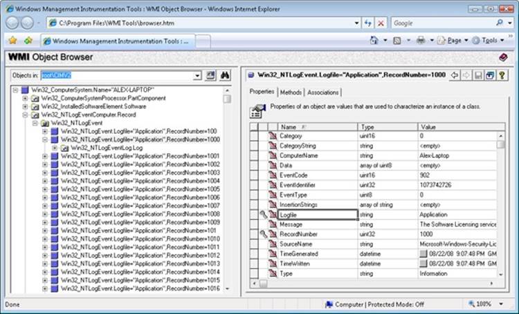
Figure 4-20. WMI Object Browser
EXPERIMENT: USING WMI SCRIPTS TO MANAGE SYSTEMS
A powerful aspect of WMI is its support for scripting languages. Microsoft has generated hundreds of scripts that perform common administrative tasks for managing user accounts, files, the registry, processes, and hardware devices. The Microsoft TechNet Scripting Center website serves as the central location for Microsoft scripts. Using a script from the scripting center is as easy as copying its text from your Internet browser, storing it in a file with a .vbs extension, and running it with the command cscript script.vbs, where script is the name you gave the script. Cscript is the command-line interface to Windows Script Host (WSH).
Here’s a sample TechNet script that registers to receive events when Win32_Process object instances are created, which occurs whenever a process starts, and prints a line with the name of the process that the object represents:
strComputer = "."
Set objWMIService = GetObject("winmgmts:" _
& "{impersonationLevel=impersonate}!\\" & strComputer & "\root\cimv2")
Set colMonitoredProcesses = objWMIService. _
ExecNotificationQuery("select * from __instancecreationevent " _
& " within 1 where TargetInstance isa 'Win32_Process'")
i = 0
Do While i = 0
Set objLatestProcess = colMonitoredProcesses.NextEvent
Wscript.Echo objLatestProcess.TargetInstance.Name
Loop
The line that invokes ExecNotificationQuery does so with a parameter that includes a “select” statement, which highlights WMI’s support for a read-only subset of the ANSI standard Structured Query Language (SQL), known as WQL, to provide a flexible way for WMI consumers to specify the information they want to extract from WMI providers. Running the sample script with Cscript and then starting Notepad results in the following output:
C:\>cscript monproc.vbs
Microsoft (R) Windows Script Host Version 5.7
Copyright (C) Microsoft Corporation. All rights reserved.
NOTEPAD.EXE
WMI Implementation
The WMI service runs in a shared Svchost process that executes in the local system account. It loads providers into the Wmiprvse.exe provider-hosting process, which launches as a child of the RPC service process. WMI executes Wmiprvse in the local system, local service, or network service account, depending on the value of the HostingModel property of the WMI Win32Provider object instance that represents the provider implementation. A Wmiprvse process exits after the provider is removed from the cache, one minute following the last provider request it receives.
EXPERIMENT: VIEWING WMIPRVSE CREATION
You can see Wmiprvse being created by running Process Explorer and executing Wmic. A Wmiprvse process will appear beneath the Svchost process that hosts the RPC service. If Process Explorer job highlighting is enabled, it will appear with the job highlight color because, to prevent a runaway provider from consuming all virtual memory resources on a system, Wmiprvse executes in a job object that limits the number of child processes it can create and the amount of virtual memory each process and all the processes of the job can allocate. (See Chapter 5 for more information on job objects.)
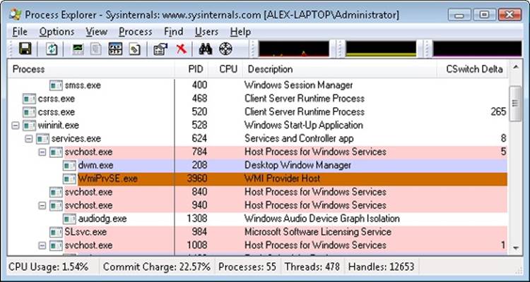
Most WMI components reside by default in %SystemRoot%\System32 and %SystemRoot%\System32\Wbem, including Windows MOF files, built-in provider DLLs, and management application WMI DLLs. Look in the %SystemRoot%\System32\Wbem directory, and you’ll find Ntevt.mof, the Event Log provider MOF file. You’ll also find Ntevt.dll, the Event Log provider’s DLL, which the WMI service uses.
Directories beneath %SystemRoot%\System32\Wbem store the repository, log files, and third-party MOF files. WMI implements the repository—named the CIMOM object repository—using a proprietary version of the Microsoft JET database engine. The database file, by default, resides in %SystemRoot%\System32\Wbem\Repository\.
WMI honors numerous registry settings that the service’s HKLM\SOFTWARE\Microsoft\WBEM\CIMOM registry key stores, such as thresholds and maximum values for certain parameters.
Device drivers use special interfaces to provide data to and accept commands—called the WMI System Control commands—from WMI. These interfaces are part of the WDM, which is explained in Chapter 8, “I/O System,” in Part 2. Because the interfaces are cross-platform, they fall under the \root \WMI namespace.
WMIC
Windows also includes Wmic.exe, a utility that allows you to interact with WMI from a WMI-aware command-line shell. All WMI objects and their properties, including their methods, are accessible through the shell, which makes WMIC an advanced systems management console.
WMI Security
WMI implements security at the namespace level. If a management application successfully connects to a namespace, the application can view and access the properties of all the objects in that namespace. An administrator can use the WMI Control application to control which users can access a namespace. Internally, this security model is implemented by using ACLs and Security Descriptors, part of the standard Windows security model that implements Access Checks. (See Chapter 6 for more information on access checks.)
To start the WMI Control application, from the Start menu, select Control Panel. From there, select System And Maintenance, Administrative Tools, Computer Management. Next, open the Services And Applications branch. Right-click WMI Control, and select Properties to launch the WMI Control Properties dialog box, which Figure 4-21 shows. To configure security for namespaces, click on the Security tab, select the namespace, and click Security. The other tabs in the WMI Control Properties dialog box let you modify the performance and backup settings that the registry stores.
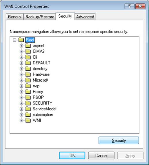
Figure 4-21. WMI security properties
Windows Diagnostic Infrastructure
The Windows Diagnostic Infrastructure (WDI) helps to detect, diagnose, and resolve common problem scenarios with minimal user intervention. Windows components implement triggers that cause WDI to launch scenario-specific troubleshooting modules to detect the occurrence of a problem scenario. A trigger can indicate that the system is approaching or has reached a problematic state. Once a troubleshooting module has identified a root cause, it can invoke a problem resolver to address it. A resolution might be as simple as changing a registry setting or interacting with the user to perform recovery steps or configuration changes. Ultimately, WDI’s main role is to provide a unified framework for Windows components to perform the tasks involved in automated problem detection, diagnosis, and resolution.
WDI Instrumentation
Windows or application components must add instrumentation to notify WDI when a problem scenario is occurring. Components can wait for the results of diagnosis synchronously or can continue operating and let diagnosis proceed asynchronously. WDI implements two different types of instrumentation APIs to support these models:
§ Event-based diagnosis, which can be used for minimally invasive diagnostics instrumentation, can be added to a component without requiring any changes to its implementation. WDI supports two kinds of event-based diagnosis: simple scenarios and start-stop scenarios. In a simple scenario, a single point in code is responsible for the failure and an event is raised to trigger diagnostics. In a start-stop scenario, an entire code path is deemed risky and is instrumented for diagnosis. One event is raised at the beginning of the scenario to a real-time Event Tracing for Windows (ETW) session named the DiagLog. At the same time, a kernel facility called the Scenario Event Mapper (SEM) enables a collection of additional ETW traces to the WDI context loggers. A second event is raised to signal the end of the diagnostic scenario, at which time the SEM disables the verbose tracing. This “just-in-time tracing” mechanism keeps the performance overhead of detailed tracing low while maintaining enough contextual information for WDI to find the root cause without a reproduction of the problem, if a failure should occur.
§ On-demand diagnosis, which allows applications to request diagnoses on their own, interact with the diagnostic, receive notifications when the diagnostic has completed, and modify its behavior based on the results of the diagnosis. On-demand instrumentation is particularly useful when diagnosis needs to be performed in a privileged security context. WDI facilitates the transfer of context across trust and process boundaries and also supports impersonation of the caller when necessary.
Diagnostic Policy Service
The Diagnostic Policy Service (DPS, %SystemRoot%\System32\Dps.dll) implements most of the WDI scenario back end. DPS is a multithreaded service (running in a Svchost) that accepts on-demand scenario requests and also monitors and watches for diagnostic events delivered via DiagLog. (See Figure 4-22, which shows the relationship of DPS to the other key WDI components.) In response to these requests, DPS launches the appropriate troubleshooting module, which encodes domain-specific knowledge, such as how to find the root cause of a network problem. In addition, DPS makes all the contextual information related to the scenario available to the modules in the form of captured traces. Troubleshooting modules perform an automated analysis of the data and can request DPS to launch a secondary module called a resolver, which is responsible for fixing the problem, silently if possible.
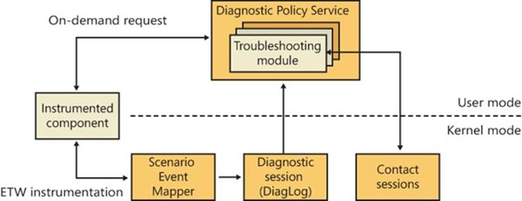
Figure 4-22. Windows Diagnostic Infrastructure architecture
DPS controls and enforces Group Policy settings for diagnostic scenarios. You can use the Group Policy Editor (%SystemRoot%\System32\Gpedit.msc) to configure the settings for the diagnostics and automatic recovery options. You can access these settings from Computer Configuration, Administrative Templates, System, Troubleshooting And Diagnostics, shown in Figure 4-23.
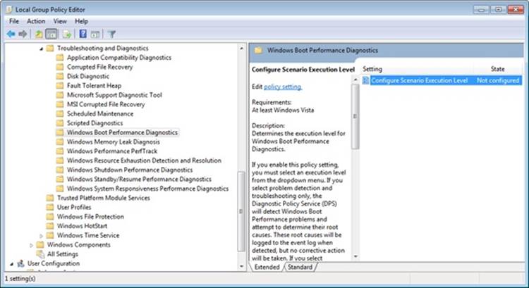
Figure 4-23. Configuring Diagnostic Policy Service settings
Diagnostic Functionality
Windows implements several built-in diagnostic scenarios and utilities. Some examples include:
§ Disk diagnostics, which include the presence of Self-Monitoring Analysis and Reporting Technology (SMART) code inside the storage class driver (%SystemRoot%\System32\Driver\Classspnp.sys) to monitor disk health. WDI notifies and guides the user through data backup after an impending disk failure is detected. In addition, Windows monitors application crashes caused by disk corruptions in critical system files. The diagnostic uses the Windows File Protection mechanism to automatically restore such damaged system files from a backup cache when possible. For more information on Windows storage management, see Chapter 9, “Storage Management,” in Part 2.
§ Network diagnostics and troubleshooting extends WDI to handle different classes of networking-related problems, such as file sharing, Internet access, wireless networks, third-party firewalls, and general network connectivity. For more information on networking, see Chapter 7.
§ Resource exhaustion prevention, which includes Windows memory leak diagnosis and Windows resource exhaustion detection and resolution. These diagnostics can detect when the commit limit is approaching its maximum and alert the user of the situation, including the top memory and resource consumers. The user can then choose to terminate these applications to attempt to free some resources. For more information on the commit limit and virtual memory, see Chapter 10, “Memory Management,” in Part 2.
§ Windows memory diagnostic tool, which can be manually executed by the user from the Boot Manager on startup or automatically recommended by Windows Error Reporting (WER) after a system crash that was analyzed as potentially the result of faulty RAM. For more information on the boot process, see Chapter 13 in Part 2.
§ Windows startup repair tool, which attempts to automatically fix certain classes of errors commonly responsible for users being unable to boot the system, such as incorrect BCD settings, damaged disk structures such as the MBR or boot sector, and faulty drivers. When system boot is unsuccessful, the Boot Manager automatically launches the startup repair tool, if it is installed, which also includes manual recovery options and access to a command prompt. For more information on the startup repair tool, see Chapter 13 in Part 2.
§ Windows performance diagnostics, which include Windows boot performance diagnostics, Windows shutdown performance diagnostics, Windows standby/resume performance diagnostics, and Windows system responsiveness performance diagnostics. Based on certain timing thresholds and the internal behavioral expectations of these mechanisms, Windows can detect problems caused by slow performance and log them to the Event Log, which in turn is used by WDI to provide resolutions and walkthroughs for the user to attempt to fix the problem.
§ Program Compatibility Assistant (PCA), which enables legacy applications to execute on newer Windows versions despite compatibility problems. PCA detects application installation failures caused by a mismatch during version checks and run-time failures caused by deprecated binaries and User Account Control (UAC) settings. PCA attempts to recover from these failures by applying the appropriate compatibility setting for the application, which takes effect during the next run. In addition, PCA maintains a database of programs with known compatibility issues and informs the users about potential problems at program startup.
Conclusion
So far, we’ve examined the overall structure of Windows, the core system mechanisms on which the structure is built, and core management mechanisms. With this foundation laid, we’re ready to explore the individual executive components in more detail, starting with processes and threads.
All materials on the site are licensed Creative Commons Attribution-Sharealike 3.0 Unported CC BY-SA 3.0 & GNU Free Documentation License (GFDL)
If you are the copyright holder of any material contained on our site and intend to remove it, please contact our site administrator for approval.
© 2016-2026 All site design rights belong to S.Y.A.