Windows Internals, Sixth Edition, Part 2 (2012)
Chapter 8. I/O System
The Windows I/O system consists of several executive components that together manage hardware devices and provide interfaces to hardware devices for applications and the system. In this chapter, we’ll first list the design goals of the I/O system, which have influenced its implementation. We’ll then cover the components that make up the I/O system, including the I/O manager, Plug and Play (PnP) manager, and power manager. Then we’ll examine the structure and components of the I/O system and the various types of device drivers. We’ll look at the key data structures that describe devices, device drivers, and I/O requests, after which we’ll describe the steps necessary to complete I/O requests as they move through the system. Finally, we’ll present the way device detection, driver installation, and power management work.
I/O System Components
The design goals for the Windows I/O system are to provide an abstraction of devices, both hardware (physical) and software (virtual or logical), to applications with the following features:
§ Uniform security and naming across devices to protect shareable resources. (See Chapter 6, “Security,” in Part 1 for a description of the Windows security model.)
§ High-performance asynchronous packet-based I/O to allow for the implementation of scalable applications.
§ Services that allow drivers to be written in a high-level language and easily ported between different machine architectures.
§ Layering and extensibility to allow for the addition of drivers that transparently modify the behavior of other drivers or devices, without requiring any changes to the driver whose behavior or device is modified.
§ Dynamic loading and unloading of device drivers so that drivers can be loaded on demand and not consume system resources when unneeded.
§ Support for Plug and Play, where the system locates and installs drivers for newly detected hardware, assigns them hardware resources they require, and also allows applications to discover and activate device interfaces.
§ Support for power management so that the system or individual devices can enter low power states.
§ Support for multiple installable file systems, including FAT, the CD-ROM file system (CDFS), the Universal Disk Format (UDF) file system, and the Windows file system (NTFS). (See Chapter 12, for more specific information on file system types and architecture.)
§ Windows Management Instrumentation (WMI) support and diagnosability so that drivers can be managed and monitored through WMI applications and scripts. (WMI is described in Chapter 4, “Management Mechanisms,” in Part 1.)
To implement these features the Windows I/O system consists of several executive components as well as device drivers, which are shown in Figure 8-1.
§ The I/O manager is the heart of the I/O system. It connects applications and system components to virtual, logical, and physical devices, and it defines the infrastructure that supports device drivers.
§ A device driver typically provides an I/O interface for a particular type of device. A driver is a software module that interprets high-level commands, such as read or write, and issues low-level, device-specific commands, such as writing to control registers. Device drivers receive commands routed to them by the I/O manager that are directed at the devices they manage, and they inform the I/O manager when those commands are complete. Device drivers often use the I/O manager to forward I/O commands to other device drivers that share in the implementation of a device’s interface or control.
§ The PnP manager works closely with the I/O manager and a type of device driver called a bus driver to guide the allocation of hardware resources as well as to detect and respond to the arrival and removal of hardware devices. The PnP manager and bus drivers are responsible for loading a device’s driver when the device is detected. When a device is added to a system that doesn’t have an appropriate device driver, the executive Plug and Play component calls on the device installation services of a user-mode PnP manager.
§ The power manager also works closely with the I/O manager and the PnP manager to guide the system, as well as individual device drivers, through power-state transitions.
§ Windows Management Instrumentation support routines, called the Windows Driver Model (WDM) WMI provider, allow device drivers to indirectly act as providers, using the WDM WMI provider as an intermediary to communicate with the WMI service in user mode. (For more information on WMI, see the section “Windows Management Instrumentation” in Chapter 4 in Part 1.)
§ The registry serves as a database that stores a description of basic hardware devices attached to the system as well as driver initialization and configuration settings. (See “The Registry” section in Chapter 4 in Part 1 for more information.)
§ INF files, which are designated by the .inf extension, are driver installation files. INF files are the link between a particular hardware device and the driver that assumes primary control of the device. They are made up of script-like instructions describing the device they correspond to, the source and target locations of driver files, required driver-installation registry modifications, and driver dependency information. Digital signatures that Windows uses to verify that a driver file has passed testing by the Microsoft Windows Hardware Quality Labs (WHQL) are stored in .cat files. Digital signatures are also used to prevent tampering of the driver or its INF file.
§ The hardware abstraction layer (HAL) insulates drivers from the specifics of the processor and interrupt controller by providing APIs that hide differences between platforms. In essence, the HAL is the bus driver for all the devices soldered onto the computer’s motherboard that aren’t controlled by other drivers.
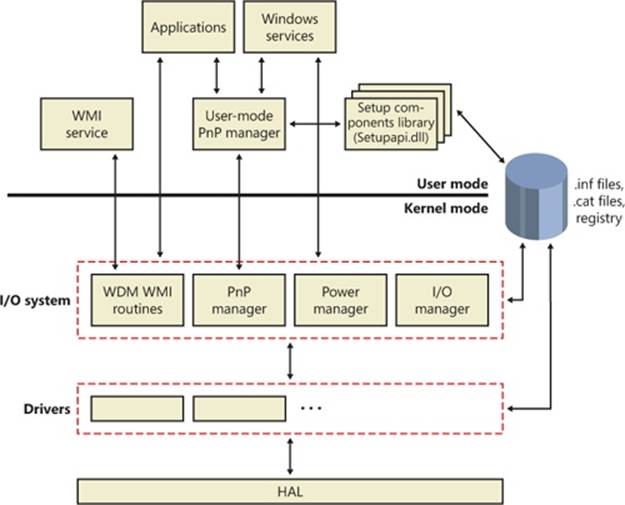
Figure 8-1. I/O system components
The I/O Manager
The I/O manager is the core of the I/O system because it defines the orderly framework, or model, within which I/O requests are delivered to device drivers. The I/O system is packet driven. Most I/O requests are represented by an I/O request packet (IRP), which travels from one I/O system component to another. (As you’ll discover in the section Fast I/O, fast I/O is the exception; it doesn’t use IRPs.) The design allows an individual application thread to manage multiple I/O requests concurrently. An IRP is a data structure that contains information completely describing an I/O request. (You’ll find more information about IRPs in the section I/O Request Packets later in the chapter.)
The I/O manager creates an IRP in memory to represent an I/O operation, passing a pointer to the IRP to the correct driver and disposing of the packet when the I/O operation is complete. In contrast, a driver receives an IRP, performs the operation the IRP specifies, and passes the IRP back to the I/O manager, either because the requested I/O operation has been completed, or because it must be passed on to another driver for further processing.
In addition to creating and disposing of IRPs, the I/O manager supplies code that is common to different drivers and that the drivers can call to carry out their I/O processing. By consolidating common tasks in the I/O manager, individual drivers become simpler and more compact. For example, the I/O manager provides a function that allows one driver to call other drivers. It also manages buffers for I/O requests, provides timeout support for drivers, and records which installable file systems are loaded into the operating system. There are close to one hundred different routines in the I/O manager that can be called by device drivers.
The I/O manager also provides flexible I/O services that allow environment subsystems, such as Windows and POSIX, to implement their respective I/O functions. These services include sophisticated services for asynchronous I/O that allow developers to build scalable, high-performance server applications.
The uniform, modular interface that drivers present allows the I/O manager to call any driver without requiring any special knowledge of its structure or internal details. The operating system treats all I/O requests as if they were directed at a file; the driver converts the requests from requests made to a virtual file to hardware-specific requests. Drivers can also call each other (using the I/O manager) to achieve layered, independent processing of an I/O request.
Besides providing the normal open, close, read, and write functions, the Windows I/O system provides several advanced features, such as asynchronous, direct, buffered, and scatter/gather I/O, which are described in the Types of I/O section later in this chapter.
Typical I/O Processing
Most I/O operations don’t involve all the components of the I/O system. A typical I/O request starts with an application executing an I/O-related function (for example, reading data from a device) that is processed by the I/O manager, one or more device drivers, and the HAL.
As just mentioned, in Windows, threads perform I/O on virtual files. A virtual file refers to any source or destination for I/O that is treated as if it were a file (such as files, directories, pipes, and mailslots). The operating system abstracts all I/O requests as operations on a virtual file, because the I/O manager has no knowledge of anything but files, therefore making it the responsibility of the driver to translate file-oriented comments (open, close, read, write) into device-specific commands. This abstraction thereby generalizes an application’s interface to devices.User-mode applications (whether Windows or POSIX) call documented functions, which in turn call internal I/O system functions to read from a file, write to a file, and perform other operations. The I/O manager dynamically directs these virtual file requests to the appropriate device driver. Figure 8-2 illustrates the basic structure of a typical I/O request flow.
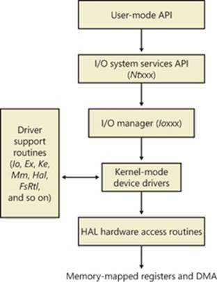
Figure 8-2. The flow of a typical I/O request
In the following sections, we’ll look at these components more closely, covering the various types of device drivers, how they are structured, how they load and initialize, and how they process I/O requests. Then we’ll cover the operation and roles of the PnP manager and the power manager.
Device Drivers
To integrate with the I/O manager and other I/O system components, a device driver must conform to implementation guidelines specific to the type of device it manages and the role it plays in managing the device. In this section, we’ll look at the types of device drivers Windows supports as well as the internal structure of a device driver.
Types of Device Drivers
Windows supports a wide range of device driver types and programming environments. Even within a type of device driver, programming environments can differ, depending on the specific type of device for which a driver is intended. The broadest classification of a driver is whether it is a user-mode or kernel-mode driver. Windows supports a couple of types of user-mode drivers:
§ Windows subsystem printer drivers translate device-independent graphics requests to printer-specific commands. These commands are then typically forwarded to a kernel-mode port driver such as the universal serial bus (USB) printer port driver (Usbprint.sys).
§ User-Mode Driver Framework (UMDF) drivers are hardware device drivers that run in user mode. They communicate to the kernel-mode UMDF support library through ALPC. See the User-Mode Driver Framework (UMDF) section later in this chapter for more information.
In this chapter, the focus is on kernel-mode device drivers. There are many types of kernel-mode drivers, which can be divided into the following basic categories:
§ File system drivers accept I/O requests to files and satisfy the requests by issuing their own, more explicit, requests to mass storage or network device drivers.
§ Plug and Play drivers work with hardware and integrate with the Windows power manager and PnP manager. They include drivers for mass storage devices, video adapters, input devices, and network adapters.
§ Non–Plug and Play drivers, which also include kernel extensions, are drivers or modules that extend the functionality of the system. They do not typically integrate with the PnP or power managers because they typically do not manage an actual piece of hardware. Examples include network API and protocol drivers. Process Monitor’s driver, described in Chapter 4 in Part 1, is also an example.
Within the category of kernel-mode drivers are further classifications based on the driver model that the driver adheres to and its role in servicing device requests.
WDM Drivers
WDM drivers are device drivers that adhere to the Windows Driver Model (WDM). WDM includes support for Windows power management, Plug and Play, and WMI, and most Plug and Play drivers adhere to WDM. There are three types of WDM drivers:
§ Bus drivers manage a logical or physical bus. Examples of buses include PCMCIA, PCI, USB, and IEEE 1394. A bus driver is responsible for detecting and informing the PnP manager of devices attached to the bus it controls as well as managing the power setting of the bus.
§ Function drivers manage a particular type of device. Bus drivers present devices to function drivers via the PnP manager. The function driver is the driver that exports the operational interface of the device to the operating system. In general, it’s the driver with the most knowledge about the operation of the device.
§ Filter drivers logically layer either above or below function drivers (these are called function filters) or above the bus driver (these are called bus filters), augmenting or changing the behavior of a device or another driver. For example, a keyboard capture utility could be implemented with a keyboard filter driver that layers above the keyboard function driver.
In WDM, no one driver is responsible for controlling all aspects of a particular device. The bus driver is responsible for detecting bus membership changes (device addition or removal), assisting the PnP manager in enumerating the devices on the bus, accessing bus-specific configuration registers, and, in some cases, controlling power to devices on the bus. The function driver is generally the only driver that accesses the device’s hardware.
Layered Drivers
Support for an individual piece of hardware is often divided among several drivers, each providing a part of the functionality required to make the device work properly. In addition to WDM bus drivers, function drivers, and filter drivers, hardware support might be split between the following components:
§ Class drivers implement the I/O processing for a particular class of devices, such as disk, keyboard, or CD-ROM, where the hardware interfaces have been standardized, so one driver can serve devices from a wide variety of manufacturers.
§ Miniclass drivers implement I/O processing that is vendor-defined for a particular class of devices. For example, although there is a standardized battery class driver written by Microsoft, both uninterruptible power supplies (UPS) and laptop batteries have highly specific interfaces that differ wildly between manufacturers, such that a miniclass is required from the vendor. Miniclass drivers are essentially kernel-mode DLLs and do not do IRP processing directly—the class driver calls into them, and they import functions from the class driver.
§ Port drivers implement the processing of an I/O request specific to a type of I/O port, such as SATA, and are implemented as kernel-mode libraries of functions rather than actual device drivers. Port drivers are almost always written by Microsoft because the interfaces are typically standardized in such a way that different vendors can still share the same port driver. However, in certain cases, third parties may need to write their own for specialized hardware. In some cases, the concept of “I/O port” extends to cover logical ports as well. For example, NDIS is the network “port” driver, and Dxgport/Videoprt are the DirectX/video “port” drivers.
§ Miniport drivers map a generic I/O request to a type of port into an adapter type, such as a specific network adapter. Miniport drivers are actual device drivers that import the functions supplied by a port driver. Miniport drivers are written by third parties, and they provide the interface for the port driver. Like miniclass drivers, they are kernel-mode DLLs and do not do IRP processing directly.
A simplified example for illustrative purposes will help demonstrate how device drivers work at a high level. A file system driver accepts a request to write data to a certain location within a particular file. It translates the request into a request to write a certain number of bytes to the disk at a particular (that is, the logical) location. It then passes this request (via the I/O manager) to a simple disk driver. The disk driver, in turn, translates the request into a physical location on the disk and communicates with the disk to write the data. This layering is illustrated inFigure 8-3.
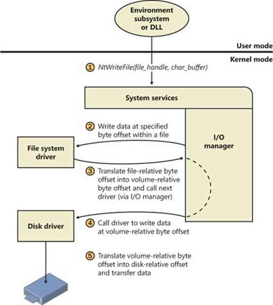
Figure 8-3. Layering of a file system driver and a disk driver
This figure illustrates the division of labor between two layered drivers. The I/O manager receives a write request that is relative to the beginning of a particular file. The I/O manager passes the request to the file system driver, which translates the write operation from a file-relative operation to a starting location (a sector boundary on the disk) and a number of bytes to write. The file system driver calls the I/O manager to pass the request to the disk driver, which translates the request to a physical disk location and transfers the data.
Because all drivers—both device drivers and file system drivers—present the same framework to the operating system, another driver can easily be inserted into the hierarchy without altering the existing drivers or the I/O system. For example, several disks can be made to seem like a very large single disk by adding a driver. This logical, volume manager driver is located between the file system and the disk drivers, as shown in the conceptual, simplified architectural diagram presented in Figure 8-4. (For the actual storage driver stack diagram, see Figure 9-3 inChapter 9). Volume manager drivers are described in more detail in Chapter 9.
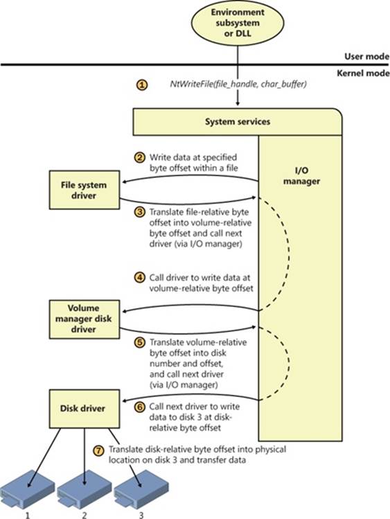
Figure 8-4. Adding a layered driver
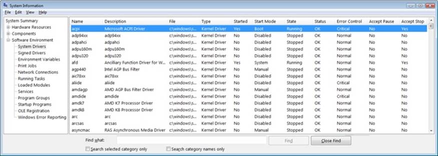
EXPERIMENT: VIEWING THE LOADED DRIVER LIST
You can see a list of registered drivers by executing the Msinfo32.exe utility from the Run dialog box of the Start menu. Select the System Drivers entry under Software Environment to see the list of drivers configured on the system. Those that are loaded have the text “Yes” in the Started column, as shown here:
You can also view the list of loaded kernel-mode drivers with Process Explorer from Windows Sysinternals (http://www.microsoft.com/technet/sysinternals). Run Process Explorer, select the System process, and select DLLs from the Lower Pane View menu entry in the View menu:
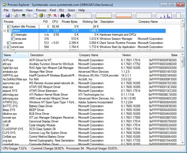
Process Explorer lists the loaded drivers, their names, version information (including company and description), and load address (assuming you have configured Process Explorer to display the corresponding columns).
Finally, if you’re looking at a crash dump (or live system) with the kernel debugger, you can get a similar display with the kernel debugger lm kv command:
lkd> lm kv
start end module name
82007000 823c0000 nt (pdb symbols)
c:\programming\symbols\ntkrpamp.pdb\37D328E3BAE5460F8E662756ED80951D2\ntkrpamp.pdb
Loaded symbol image file: ntkrpamp.exe
Image path: ntkrpamp.exe
Image name: ntkrpamp.exe
Timestamp: Fri Jan 18 21:30:58 2008 (47918B12)
CheckSum: 00372038
ImageSize: 003B9000
File version: 6.0.6001.18000
Product version: 6.0.6001.18000
File flags: 0 (Mask 3F)
File OS: 40004 NT Win32
File type: 1.0 App
File date: 00000000.00000000
Translations: 0409.04b0
CompanyName: Microsoft Corporation
ProductName: Microsoft® Windows® Operating System
InternalName: ntkrpamp.exe
OriginalFilename: ntkrpamp.exe
ProductVersion: 6.0.6001.18000
FileVersion: 6.0.6001.18000 (longhorn_rtm.080118-1840)
FileDescription: NT Kernel & System
LegalCopyright: © Microsoft Corporation. All rights reserved.
823c0000 823f3000 hal (deferred)
Image path: halmacpi.dll
Image name: halmacpi.dll
Timestamp: Fri Jan 18 21:27:20 2008 (47918A38)
CheckSum: 0003859F
ImageSize: 00033000
Translations: 0000.04b0 0000.04e0 0409.04b0 0409.04e0
82600000 82671000 ksecdd (deferred)
Image path: \SystemRoot\System32\Drivers\ksecdd.sys
Image name: ksecdd.sys
Timestamp: Fri Jan 18 21:41:20 2008 (47918D80)
CheckSum: 0006E742
ImageSize: 00071000
Translations: 0000.04b0 0000.04e0 0409.04b0 0409.04e0
Structure of a Driver
The I/O system drives the execution of device drivers. Device drivers consist of a set of routines that are called to process the various stages of an I/O request. Figure 8-5 illustrates the key driver-function routines.
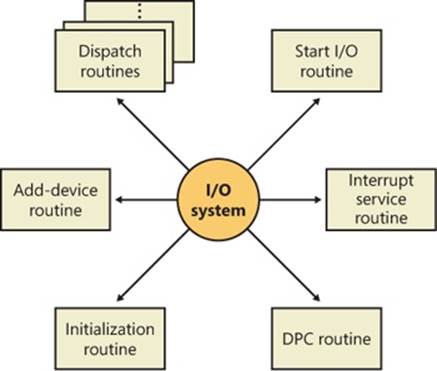
Figure 8-5. Primary device driver routines
§ An initialization routine The I/O manager executes a driver’s initialization routine, which is set by the WDK to GSDriverEntry, when it loads the driver into the operating system. GSDriverEntry initializes the compiler’s protection against stack-overflow errors (called a cookie) and then calls DriverEntry, which is what the driver writer must implement. The routine fills in system data structures to register the rest of the driver’s routines with the I/O manager and performs any global driver initialization that’s necessary.
§ An add-device routine A driver that supports Plug and Play implements an add-device routine. The PnP manager sends a notification to the driver via this routine whenever a device for which the driver is responsible is detected. In this routine, a driver typically creates a device object (described later in this chapter) to represent the device.
§ A set of dispatch routines Dispatch routines are the main entry points that a device driver provides. Some examples are open, close, read, and write and any other capabilities the device, file system, or network supports. When called on to perform an I/O operation, the I/O manager generates an IRP and calls a driver through one of the driver’s dispatch routines.
§ A start I/O routine A driver can use a start I/O routine to initiate a data transfer to or from a device. This routine is defined only in drivers that rely on the I/O manager to queue their incoming I/O requests. The I/O manager serializes IRPs for a driver by ensuring that the driver processes only one IRP at a time. Drivers can process multiple IRPs concurrently, but serialization is usually required for most devices because they cannot concurrently handle multiple I/O requests.
§ An interrupt service routine (ISR) When a device interrupts, the kernel’s interrupt dispatcher transfers control to this routine. In the Windows I/O model, ISRs run at device interrupt request level (DIRQL), so they perform as little work as possible to avoid blocking lower IRQL interrupts. (See Chapter 3, “System Mechanisms,” in Part 1 for more information on IRQLs.) An ISR usually queues a deferred procedure call (DPC), which runs at a lower IRQL (DPC/dispatch level), to execute the remainder of interrupt processing. (Only drivers for interrupt-driven devices have ISRs; a file system driver, for example, doesn’t have one.)
§ An interrupt-servicing DPC routine A DPC routine performs most of the work involved in handling a device interrupt after the ISR executes. The DPC routine executes at a lower IRQL (DPC/dispatch level) than that of the ISR, which runs at device level, to avoid blocking other interrupts. A DPC routine initiates I/O completion and starts the next queued I/O operation on a device.
Although the following routines aren’t shown in Figure 8-5, they’re found in many types of device drivers:
§ One or more I/O completion routines A layered driver might have I/O completion routines that will notify it when a lower-level driver finishes processing an IRP. For example, the I/O manager calls a file system driver’s I/O completion routine after a device driver finishes transferring data to or from a file. The completion routine notifies the file system driver about the operation’s success, failure, or cancellation, and it allows the file system driver to perform cleanup operations.
§ A cancel I/O routine If an I/O operation can be canceled, a driver can define one or more cancel I/O routines. When the driver receives an IRP for an I/O request that can be canceled, it assigns a cancel routine to the IRP, and as the IRP goes through various stages of processing, this routine can change, or outright disappear, if the current operation is not cancellable. If a thread that issues an I/O request exits before the request is completed or cancels the operation (with the CancelIo Windows function, for example), the I/O manager executes the IRP’s cancel routine if one is assigned to it. A cancel routine is responsible for performing whatever steps are necessary to release any resources acquired during the processing that has already taken place for the IRP as well as for completing the IRP with a canceled status.
§ Fast dispatch routines Drivers that make use of the cache manager in Windows (see Chapter 11, for more information on the cache manager), such as file system drivers, typically provide these routines to allow the kernel to bypass typical I/O processing when accessing the driver. For example, operations such as reading or writing can be quickly performed by accessing the cached data directly, instead of taking the I/O manager’s usual path that generates discrete I/O operations. Fast dispatch routines are also used as a mechanism for callbacks from the memory manager and cache manager to file system drivers. For instance, when creating a section, the memory manager calls back into the file system driver to acquire the file exclusively.
§ An unload routine An unload routine releases any system resources a driver is using so that the I/O manager can remove the driver from memory. Any resources acquired in the initialization routine (DriverEntry) are usually released in the unload routine. A driver can be loaded and unloaded while the system is running if the driver supports it, but the unload routine will be called only after all file handles to the device are closed.
§ A system shutdown notification routine This routine allows driver cleanup on system shutdown.
§ Error-logging routines When unexpected errors occur (for example, when a disk block goes bad), a driver’s error-logging routines note the occurrence and notify the I/O manager. The I/O manager writes this information to an error log file.
NOTE
Most kernel-mode device drivers are written in C. Starting with the Windows Driver Kit 8.0, drivers can also be safely written in C++ due to specific support for kernel-mode C++ in the new compilers. Use of assembly language is highly discouraged because of the complexity it introduces and its effect of making a driver difficult to port between hardware architectures such as the x86, x64, and IA64.
Driver Objects and Device Objects
When a thread opens a handle to a file object (described in the I/O Processing section later in this chapter), the I/O manager must determine from the file object’s name which driver it should call to process the request. Furthermore, the I/O manager must be able to locate this information the next time a thread uses the same file handle. The following system objects fill this need:
§ A driver object represents an individual driver in the system. The I/O manager obtains the address of each of the driver’s dispatch routines (entry points) from the driver object.
§ A device object represents a physical or logical device on the system and describes its characteristics, such as the alignment it requires for buffers and the location of its device queue to hold incoming IRPs. It is the target for all I/O operations because this object is what the handle communicates with.
The I/O manager creates a driver object when a driver is loaded into the system, and it then calls the driver’s initialization routine (DriverEntry), which fills in the object attributes with the driver’s entry points.
At any time after loading, a driver creates device objects to represent logical or physical devices, or even a logical interface or endpoint to the driver, by calling IoCreateDevice or IoCreateDeviceSecure. However, most Plug and Play drivers create devices with their add-device routine when the PnP manager informs them of the presence of a device for them to manage. Non–Plug and Play drivers, on the other hand, usually create device objects when the I/O manager invokes their initialization routine. The I/O manager unloads a driver when the driver’s last device object has been deleted and no references to the driver remain.
When a driver creates a device object, the driver can optionally assign the device a name. A name places the device object in the object manager namespace, and a driver can either explicitly define a name or let the I/O manager autogenerate one. (The object manager namespace is described in Chapter 3 in Part 1.) By convention, device objects are placed in the \Device directory in the namespace, which is inaccessible by applications using the Windows API.
NOTE
Some drivers place device objects in directories other than \Device. For example, the IDE driver creates the device objects that represent IDE ports and channels in the \Device\Ide directory. See Chapter 9 for a description of storage architecture, including the way storage drivers use device objects.
If a driver needs to make it possible for applications to open the device object, it must create a symbolic link in the \Global?? directory to the device object’s name in the \Device directory. (See Chapter 3 in Part 1 for more information on \??.) Non–Plug and Play and file system drivers typically create a symbolic link with a well-known name (for example, \Device\Hardware2). Because well-known names don’t work well in an environment in which hardware appears and disappears dynamically, PnP drivers expose one or more interfaces by calling theIoRegisterDeviceInterface function, specifying a GUID (globally unique identifier) that represents the type of functionality exposed. GUIDs are 128-bit values that you can generate by using a tool called Uuidgen, which is included with the WDK and the Windows SDK. Given the range of values that 128 bits represents, it’s statistically almost certain that each GUID that Uuidgen creates will be forever and globally unique.
IoRegisterDeviceInterface generates the symbolic link associated with a device instance; however, a driver must call IoSetDeviceInterfaceState to enable the interface to the device before the I/O manager actually creates the link. Drivers usually do this when the PnP manager starts the device by sending the driver a start-device IRP—in this case, IRP_MJ_PNP, IRP_MN_START_DEVICE.
An application wanting to open a device object whose interfaces are represented with a GUID can call Plug and Play setup functions in user space, such as SetupDiEnumDeviceInterfaces, to enumerate the interfaces present for a particular GUID and to obtain the names of the symbolic links it can use to open the device objects. For each device reported by SetupDiEnumDeviceInterfaces, an application executes SetupDiGetDeviceInterfaceDetail to obtain additional information about the device, such as its autogenerated name. After obtaining a device’s name from SetupDiGetDeviceInterfaceDetail, the application can execute the Windows function CreateFile to open the device and obtain a handle.
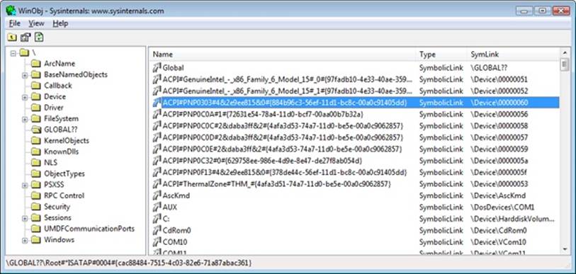
EXPERIMENT: LOOKING AT DEVICE OBJECTS
You can use the WinObj tool from Sysinternals or the !object kernel debugger command to view the device names under \Device in the object manager namespace. The following screen shot shows an I/O manager–assigned symbolic link that points to a device object in \Device with an autogenerated name:
When you run the !object kernel debugger command and specify the \Device directory, you should see output similar to the following:
lkd> !object \Device
Object: 8b611b88 Type: (84d10d40) Directory
ObjectHeader: 8b611b70 (old version)
HandleCount: 0 PointerCount: 365
Directory Object: 8b602470 Name: Device
Hash Address Type Name
---- ------- ---- ----
00 85557a00 Device KsecDD
855589d8 Device Ndis
8b6151b0 SymbolicLink {941D252A-0BDA-4772-B3CB-30697579BD4A}
86859030 Device 0000009b
88c92da8 Device SrvNet
886723f0 Device Beep
8b71fb90 SymbolicLink ScsiPort2
84d17a98 Device 00000032
84d15f00 Device 00000025
84d13030 Device 00000019
01 86d44030 Device NDMP10
8d291eb0 SymbolicLink {E85EEE75-32E3-4A94-8905-52709C2C9BCC}
886da3c8 Device Netbios
86862030 Device 0000009c
84d177c8 Device 00000033
84d15c70 Device 00000026
02 86de9030 Device NDMP11
84d19320 Device 00000040
88633ca0 Device NetBT_Tcpip_{033C65A4-C1D6-4824-B420-DDAEADFF873E}
8b7dcdd0 SymbolicLink Ip
84d17500 Device 00000034
84d159a8 Device 00000027
03 86df3380 Device NDMP12
8515ede0 Device WMIAdminDevice
84d1a030 Device 00000041
8862e040 Device Video0
86eaec28 Device KeyboardClass0
84d03b00 Device KMDF0
84d17230 Device 00000035
84d156e0 Device 00000028
04 86e0d030 Device NDMP13
86e65030 Device NDMP20
85541030 Device VolMgrControl
86e6c358 Device Tun0
84d1ad68 Device 00000042
8862ec48 Device Video1
88e15158 Device 0000009f
9badd848 SymbolicLink MailslotRedirector
86e1d488 Device KeyboardClass1
...
When you enter the !object command and specify an object manager directory object, the kernel debugger dumps the contents of the directory according to the way the object manager organizes it internally. For fast lookups, a directory stores objects in a hash table based on a hash of the object names, so the output shows the objects stored in each bucket of the directory’s hash table.
As Figure 8-6 illustrates, a device object points back to its driver object, which is how the I/O manager knows which driver routine to call when it receives an I/O request. It uses the device object to find the driver object representing the driver that services the device. It then indexes into the driver object by using the function code supplied in the original request; each function code corresponds to a driver entry point. (The function codes shown in Figure 8-6 are described in the section IRP Stack Locations later in this chapter.)
A driver object often has multiple device objects associated with it. The list of device objects represents the physical or logical devices that the driver controls. For example, each partition of a hard disk has a separate device object that contains partition-specific information. However, the same hard disk driver is used to access all partitions. When a driver is unloaded from the system, the I/O manager uses the queue of device objects to determine which devices will be affected by the removal of the driver.
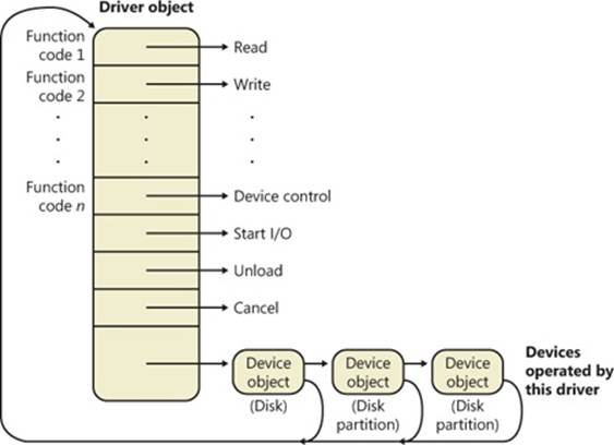
Figure 8-6. The driver object
EXPERIMENT: DISPLAYING DRIVER AND DEVICE OBJECTS
You can display driver and device objects with the kernel debugger !drvobj and !devobj commands, respectively. In the following example, the driver object for the keyboard class driver is examined, and its lone device object viewed:
lkd> !drvobj kbdclass
Driver object (86e379a0) is for:
\Driver\kbdclass
Driver Extension List: (id , addr)
Device Object list:
86e1d488 86eaec28
lkd> !devobj 86eaec28
Device object (86eaec28) is for:
KeyboardClass0 \Driver\kbdclass DriverObject 86e379a0
Current Irp 00000000 RefCount 0 Type 0000000b Flags 00002044
DevExt 86eaece0 DevObjExt 86eaedc0
ExtensionFlags (0x00000800)
Unknown flags 0x00000800
AttachedDevice (Upper) 86e15a40 \Driver\ctrl2cap
AttachedTo (Lower) 86e15020 \Driver\i8042prt
Device queue is not busy
Notice that the !devobj command also shows you the addresses and names of any device objects that the object you’re viewing is layered over (the AttachedTo line) as well as the device objects layered on top of the object specified (the AttachedDevice line).
Using objects to record information about drivers means that the I/O manager doesn’t need to know details about individual drivers. The I/O manager merely follows a pointer to locate a driver, thereby providing a layer of portability and allowing new drivers to be loaded easily.
Opening Devices
A file object is a kernel-mode data structure that represents a handle to a device. File objects clearly fit the criteria for objects in Windows: they are system resources that two or more user-mode processes can share, they can have names, they are protected by object-based security, and they support synchronization. Shared resources in the I/O system, like those in other components of the Windows executive, are manipulated as objects. (See Chapter 3 in Part 1 for a description of the object manager and Chapter 6 in Part 1 for information on object security.)
File objects provide a memory-based representation of resources that conform to an I/O-centric interface, in which they can be read from or written to. Table 8-1 lists some of the file object’s attributes. For specific field declarations and sizes, see the structure definition for FILE_OBJECT in WDM.h.
Table 8-1. File Object Attributes
|
Attribute |
Purpose |
|
File name |
Identifies the physical file that the file object refers to, which was passed in to the CreateFile API. |
|
Current byte offset |
Identifies the current location in the file (valid only for synchronous I/O). |
|
Share modes |
Indicate whether other callers can open the file for read, write, or delete operations while the current caller is using it. |
|
Open mode flags |
Indicate whether I/O will be synchronous or asynchronous, cached or noncached, sequential or random, and so on. |
|
Pointer to device object |
Indicates the type of device the file resides on. |
|
Pointer to the volume parameter block (VPB) |
Indicates the volume, or partition, that the file resides on. |
|
Pointer to section object pointers |
Indicates a root structure that describes a mapped/cached file. This structure also contains the shared cache map, which identifies which parts of the file are cached (or rather mapped) by the cache manager and where they reside in the cache. |
|
Pointer to private cache map |
Used to store per-handle caching information such as the read patterns for this handle or the page priority for the process. See Chapter 10, for more information on page priority. |
|
List of I/O request packets (IRPs) |
If thread-agnostic I/O is used (to be described later) and the file object is associated with a completion port (also described later), this is a list of all the I/O operations that are associated with this file object. |
|
I/O completion context |
Context information for the current I/O completion port, if one is active. |
|
File object extension |
Stores the I/O priority (explained later in this chapter) for the file and whether share-access checks should be performed on the file object, and contains optional file object extensions that store context-specific information. |
To maintain some level of opacity toward driver code that uses the file object, as well as to enable extending the file object functionality without enlarging the structure, the file object also contains an extension field, which allows for up to six different kinds of additional attributes. These are described in Table 8-2.
Table 8-2. File Object Extensions
|
Extension |
Purpose |
|
Transaction parameters |
Contains the transaction parameter block, which contains information about a transacted file operation. Returned by IoGetTransactionParameterBlock. |
|
Device object hint |
Identifies the device object of the filter driver with which this file should be associated. Set with IoCreateFileEx or IoCreateFileSpecifyDeviceObjectHint. |
|
I/O status block range |
Allows applications to lock a user-mode buffer into kernel-mode memory to optimize asynchronous I/Os. See the section on I/O completion port optimizations later in this chapter. Set with SetFileIoOverlappedRange. |
|
Generic |
Contains filter-driver-specific information, as well as extended create parameters (ECP) that were added by the caller. Set with IoCreateFileEx. |
|
Scheduled file I/O |
Stores a file’s bandwidth reservation information, which is used by the storage system to optimize and guarantee throughput for multimedia applications. See the section on bandwidth reservation later in this chapter. Set with SetFileBandwidthReservation. |
|
Symbolic link |
Added to the file object upon creation, when a mount point or directory junction is traversed (or a filter explicitly reparses the path). It stores the caller-supplied path, including information about any intermediate junctions, so that if a relative symbolic link is hit, it can walk back through the junctions. See Chapter 12 for more information on NTFS symbolic links, mount points, and directory junctions. |
When a caller opens a file or a simple device, the I/O manager returns a handle to a file object. Figure 8-7 illustrates what occurs when a file is opened.
In this example, (1) a C program calls the run-time library function fopen, which in turn (2) calls the Windows CreateFile function. The Windows subsystem DLL (in this case, Kernel32.dll) then (3) calls the native NtCreateFile function in Ntdll.dll. The routine in Ntdll.dll contains the appropriate instruction to cause a transition into kernel mode to the system service dispatcher, which then (4) calls the real NtCreateFile routine in Ntoskrnl.exe. (See Chapter 3 in Part 1 for more information about system service dispatching.) Finally, this routine wraps the parameters and flags in such a way that the I/O manager function IoCreateFile can actually perform the operation.
NOTE
File objects represent open instances of files, not files themselves. Unlike UNIX systems, which use vnodes, Windows does not define the representation of a file; Windows file system drivers define their own representations.
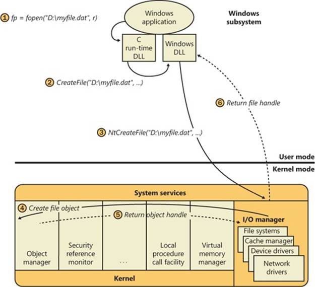
Figure 8-7. Opening a file object
Similar to executive objects, files are protected by a security descriptor that contains an access control list (ACL). The I/O manager consults the security subsystem to determine whether a file’s ACL allows the process to access the file in the way its thread is requesting. If it does (5, 6), the object manager grants the access and associates the granted access rights with the file handle that it returns. If this thread or another thread in the process needs to perform additional operations not specified in the original request, the thread must open the same file again with a different request to get another handle, which prompts another security check. (See Chapter 6 in Part 1 for more information about object protection.)
EXPERIMENT: VIEWING DEVICE HANDLES
Any process that has an open handle to a device will have a file object in its handle table corresponding to the open instance. You can view these handles with Process Explorer by selecting a process and checking Handles in the Lower Pane View submenu of the View menu. Sort by the Type column and scroll to where you see the handles that represent file objects, which are labeled as File.
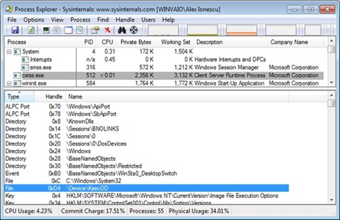
In this example, the Csrss process has a handle open to a device created by the kernel security device driver (Ksecdd.sys). You can look at the specific file object in the kernel debugger by first identifying the address of the object. The following command reports information on the highlighted handle (handle value 0xD4) in the preceding screen shot, which is in the Csrss.exe process that has a process ID of 512 (0x200):
lkd> !handle d4 f 200
Searching for Process with Cid == 200
PROCESS fffffa800bf35b30
SessionId: 0 Cid: 0200 Peb: 7fffffd8000 ParentCid: 0188
DirBase: 1dba50000 ObjectTable: fffff8a000f28d80 HandleCount: 630.
Image: csrss.exe
Handle table at fffff8a000f28d80 with 630 entries in use
00d4: Object: fffffa800c9cc9f0 GrantedAccess: 00100001 Entry: fffff8a001409350
Object: fffffa800c9cc9f0 Type: (fffffa800737a080) File
ObjectHeader: fffffa800c9cc9c0 (new version)
HandleCount: 1 PointerCount: 1
Because the object is a file object, you can get information about it with the !fileobj command:
lkd> !fileobj fffffa800c9cc9f0
Device Object: 0xfffffa8007da1550 \Driver\KSecDD
Vpb is NULL
Event signalled
Flags: 0x40002
Synchronous IO
Handle Created
CurrentByteOffset: 0
Because a file object is a memory-based representation of a shareable resource and not the resource itself, it’s different from other executive objects. A file object contains only data that is unique to an object handle, whereas the file itself contains the data or text to be shared. Each time a thread opens a file, a new file object is created with a new set of handle-specific attributes. For example, for files opened synchronously, the current byte offset attribute refers to the location in the file at which the next read or write operation using that handle will occur. Each handle to a file has a private byte offset even though the underlying file is shared. A file object is also unique to a process, except when a process duplicates a file handle to another process (by using the Windows DuplicateHandle function) or when a child process inherits a file handle from a parent process. In these situations, the two processes have separate handles that refer to the same file object.
Although a file handle is unique to a process, the underlying physical resource is not. Therefore, as with any shared resource, threads must synchronize their access to shareable resources such as files, file directories, and devices. If a thread is writing to a file, for example, it should specify exclusive write access when opening the file to prevent other threads from writing to the file at the same time. Alternatively, by using the Windows LockFile function, the thread could lock a portion of the file while writing to it when exclusive access is required.
When a file is opened, the file name includes the name of the device object on which the file resides. For example, the name \Device\HarddiskVolume1\Myfile.dat refers to the file Myfile.dat on the C: volume. The substring \Device\HarddiskVolume1 is the name of the internal Windows device object representing that volume. When opening Myfile.dat, the I/O manager creates a file object and stores a pointer to the HarddiskVolume1 device object in the file object and then returns a file handle to the caller. Thereafter, when the caller uses the file handle, the I/O manager can find the HarddiskVolume1 device object directly. Keep in mind that internal Windows device names can’t be used in Windows applications—instead, the device name must appear in a special directory in the object manager’s namespace, which is \Global??. This directory contains symbolic links to the real, internal Windows device names. As was described earlier, device drivers are responsible for creating links in this directory so that their devices will be accessible to Windows applications. You can examine or even change these links programmatically with the Windows QueryDosDevice and DefineDosDevice functions.
EXPERIMENT: VIEWING WINDOWS DEVICE NAME TO WINDOWS DEVICE NAME MAPPINGS
You can examine the symbolic links that define the Windows device namespace with the WinObj utility from Sysinternals. Run WinObj, and click on the \Global?? directory, as shown here:
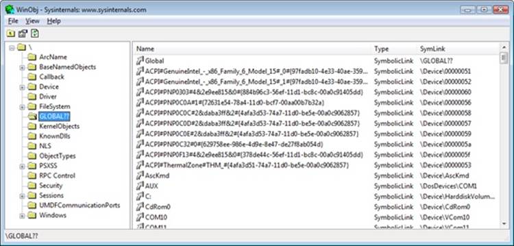
Notice the symbolic links on the right. Try right-clicking on the device C: and selecting Properties. You should see something like this:
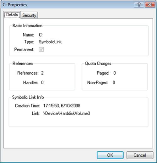
C: is a symbolic link to the internal device named \Device\HarddiskVolume3, or the first volume on the first hard drive in the system. The COM1 entry in WinObj is a symbolic link to \Device\Serial0, and so forth. Try creating your own links with the subst command at a command prompt.
I/O Processing
Now that we’ve covered the structure and types of drivers and the data structures that support them, let’s look at how I/O requests flow through the system. I/O requests pass through several predictable stages of processing. The stages vary depending on whether the request is destined for a device operated by a single-layered driver or for a device reached through a multilayered driver. Processing varies further depending on whether the caller specified synchronous or asynchronous I/O, so we’ll begin our discussion of I/O types with these two and then move on to others.
Types of I/O
Applications have several options for the I/O requests they issue. Furthermore, the I/O manager gives drivers the choice of implementing a shortcut I/O interface that can often mitigate IRP allocation for I/O processing. In this section, we’ll explain these options for I/O requests.
Synchronous and Asynchronous I/O
Most I/O operations that applications issue are synchronous (which is the default); that is, the application thread waits while the device performs the data operation and returns a status code when the I/O is complete. The program can then continue and access the transferred data immediately. When used in their simplest form, the Windows ReadFile and WriteFile functions are executed synchronously. They complete the I/O operation before returning control to the caller.
Asynchronous I/O allows an application to issue multiple I/O requests and continue executing while the device performs the I/O operation. This type of I/O can improve an application’s throughput because it allows the application thread to continue with other work while an I/O operation is in progress. To use asynchronous I/O, you must specify the FILE_FLAG_OVERLAPPED flag when you call the Windows CreateFile function. Of course, after issuing an asynchronous I/O operation, the thread must be careful not to access any data from the I/O operation until the device driver has finished the data operation. The thread must synchronize its execution with the completion of the I/O request by monitoring a handle of a synchronization object (whether that’s an event object, an I/O completion port, or the file object itself) that will be signaled when the I/O is complete.
Regardless of the type of I/O request, internally I/O operations issued to a driver on behalf of the application are performed asynchronously; that is, once an I/O request has been initiated, the device driver returns to the I/O system. Whether or not the I/O system returns immediately to the caller depends on whether the handle was opened for synchronous or asynchronous I/O. Figure 8-8 illustrates the flow of control when a read operation is initiated. Notice that if a wait is done, which depends on the overlapped flag in the file object, it is done in kernel mode by theNtReadFile function.
You can test the status of a pending asynchronous I/O operation with the Windows HasOverlappedIoCompleted macro. If you’re using I/O completion ports (described in the I/O Completion Ports section later in this chapter), you can use the GetQueuedCompletionStatus(Ex)function(s).
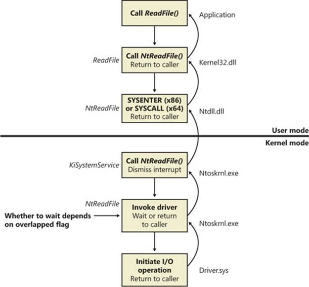
Figure 8-8. Control flow for an I/O operation
Fast I/O
Fast I/O is a special mechanism that allows the I/O system to bypass generating an IRP and instead go directly to the driver stack to complete an I/O request. (Fast I/O is described in detail in Chapters Chapter 11 and Chapter 12.) A driver registers its fast I/O entry points by entering them in a structure pointed to by the PFAST_IO_DISPATCH pointer in its driver object.
EXPERIMENT: LOOKING AT A DRIVER’S REGISTERED FAST I/O ROUTINES
The !drvobj kernel debugger command can list the fast I/O routines that a driver registers in its driver object. However, typically only file system drivers have any use for fast I/O routines, although there are exceptions, such as network protocol drivers and bus filter drivers. The following output shows the fast I/O table for the NTFS file system driver object:
lkd> !drvobj \FileSystem\Ntfs 2
Driver object (fffffa8007d9fbe0) is for:
\FileSystem\Ntfs
DriverEntry: fffff880017d406c Ntfs!GsDriverEntry
DriverStartIo: 00000000
DriverUnload: 00000000
AddDevice: 00000000
Dispatch routines:
...
Fast I/O routines:
FastIoCheckIfPossible fffff88001782230 Ntfs!NtfsFastIoCheckIfPossible
FastIoRead fffff880016efd60 Ntfs!NtfsCopyReadA
FastIoWrite fffff880016f2a10 Ntfs!NtfsCopyWriteA
FastIoQueryBasicInfo fffff880016e42e8 Ntfs!NtfsFastQueryBasicInfo
...
ReleaseForModWrite fffff8800166fee4 Ntfs!NtfsReleaseFileForModWrite
AcquireForCcFlush fffff8800167133c Ntfs!NtfsAcquireFileForCcFlush
ReleaseForCcFlush fffff880016713a0 Ntfs!NtfsReleaseFileForCcFlush
The output shows that NTFS has registered its NtfsCopyReadA routine as the fast I/O table’s FastIoRead entry. As the name of this fast I/O entry implies, the I/O manager calls this function when issuing a read I/O request if the file is cached. If the call doesn’t succeed, the standard IRP path is selected.
Mapped File I/O and File Caching
Mapped file I/O is an important feature of the I/O system, one that the I/O system and the memory manager produce jointly. (See Chapter 10 for details on how mapped files are implemented.) Mapped file I/O refers to the ability to view a file residing on disk as part of a process’s virtual memory. A program can access the file as a large array without buffering data or performing disk I/O. The program accesses memory, and the memory manager uses its paging mechanism to load the correct page from the disk file. If the application writes to its virtual address space, the memory manager writes the changes back to the file as part of normal paging.
Mapped file I/O is available in user mode through the Windows CreateFileMapping and MapViewOfFile functions. Within the operating system, mapped file I/O is used for important operations such as file caching and image activation (loading and running executable programs). The other major consumer of mapped file I/O is the cache manager. File systems use the cache manager to map file data in virtual memory to provide better response time for I/O-bound programs. As the caller uses the file, the memory manager brings accessed pages into memory. Whereas most caching systems allocate a fixed number of bytes for caching files in memory, the Windows cache grows or shrinks depending on how much memory is available. This size variability is possible because the cache manager relies on the memory manager to automatically expand (or shrink) the size of the cache, using the normal working set mechanisms explained in Chapter 10, in this case applied to the system working set. By taking advantage of the memory manager’s paging system, the cache manager avoids duplicating the work that the memory manager already performs. (The workings of the cache manager are explained in detail in Chapter 11.)
Scatter/Gather I/O
Windows also supports a special kind of high-performance I/O that is called scatter/gather, available via the Windows ReadFileScatter and WriteFileGather functions. These functions allow an application to issue a single read or write from more than one buffer in virtual memory to a contiguous area of a file on disk instead of issuing a separate I/O request for each buffer. To use scatter/gather I/O, the file must be opened for noncached I/O, the user buffers being used have to be page-aligned, and the I/Os must be asynchronous (overlapped). Furthermore, if the I/O is directed at a mass storage device, the I/O must be aligned on a device sector boundary and have a length that is a multiple of the sector size.
I/O Request Packets
The I/O request packet (IRP) is where the I/O system stores information it needs to process an I/O request. When a thread calls an I/O API, the I/O manager constructs an IRP to represent the operation as it progresses through the I/O system. If possible, the I/O manager allocates IRPs from one of three per-processor IRP nonpaged look-aside lists: the small-IRP look-aside list stores IRPs with one stack location (IRP stack locations are described shortly), the medium-IRP look-aside list contains IRPs with 4 stack locations (which can also be used for IRPs that require only 2 or 3 stack locations), and the large-IRP look-aside list contains IRPs with more than 4 stack locations—by default, the system stores IRPs with 10 stack locations on the large-IRP look-aside list, but once per minute the system adjusts the number of stack locations allocated and can increase it up to a maximum of 20, based on how many stack locations have been recently required. Additionally, these lists are backed by global look-aside lists as well, allowing efficient cross-CPU IRP flow. If an IRP requires more stack locations than are contained in the IRPs on the large-IRP look-aside list, the I/O manager allocates IRPs from nonpaged pool. After allocating and initializing an IRP, the I/O manager stores a pointer to the caller’s file object in the IRP.
NOTE
If defined, the DWORD registry value HKLM\System\CurrentControlSet\Session Manager\I/O System\LargeIrpStackLocations specifies how many stack locations are contained in IRPs stored on the large-IRP look-aside list.
Figure 8-9 shows a sample I/O request that demonstrates the relationship between an IRP and the file, device, and driver objects described in the preceding sections. Although this example shows an I/O request to a single-layered device driver, most I/O operations aren’t this direct; they involve one or more layered drivers. (This case will be shown later in this section.)
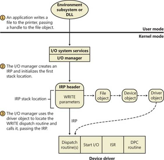
Figure 8-9. Data structures involved in a single-layered driver I/O request
IRP Stack Locations
An IRP consists of two parts: a fixed header (often referred to as the IRP’s body) and one or more stack locations. The fixed portion contains information such as the type and size of the request, whether the request is synchronous or asynchronous, a pointer to a buffer for buffered I/O, and state information that changes as the request progresses. An IRP stack location contains a function code (consisting of a major code and a minor code), function-specific parameters, and a pointer to the caller’s file object. The major function code identifies which of a driver’sdispatch routines the I/O manager invokes when passing an IRP to a driver. An optional minor function code sometimes serves as a modifier of the major function code. Power and Plug and Play commands always have minor function codes.
Most drivers specify dispatch routines to handle only a subset of possible major function codes, including create (open), read, write, device I/O control, power, Plug and Play, system control (for WMI commands), cleanup, and close. (See the following experiment for a complete listing of major function codes.) File system drivers are an example of a driver type that often fills in most or all of its dispatch entry points with functions. In contrast, a driver for a simple USB device would probably fill in only the routines needed for open, close, read, write, and sending I/O control codes. The I/O manager sets any dispatch entry points that a driver doesn’t fill to point to its own IopInvalidDeviceRequest, which completes the IRP with an error status indicating that the major function specified in the IRP is invalid for that device.
EXPERIMENT: LOOKING AT DRIVER DISPATCH ROUTINES
You can obtain a listing of the functions a driver has defined for its dispatch routines by entering a 7 after the driver object’s name (or address) in the !drvobj kernel debugger command. The following output shows that drivers support 28 IRP types.
lkd> !drvobj \Driver\kbdclass 7
Driver object (fffffa800adc2e70) is for:
\Driver\kbdclass
Driver Extension List: (id , addr)
Device Object list:
fffffa800b04fce0 fffffa800abde560
DriverEntry: fffff880071c8ecc kbdclass!GsDriverEntry
DriverStartIo: 00000000
DriverUnload: 00000000
AddDevice: fffff880071c53b4 kbdclass!KeyboardAddDevice
Dispatch routines:
[00] IRP_MJ_CREATE fffff880071bedd4 kbdclass!KeyboardClassCreate
[01] IRP_MJ_CREATE_NAMED_PIPE fffff800036abc0c nt!IopInvalidDeviceRequest
[02] IRP_MJ_CLOSE fffff880071bf17c kbdclass!KeyboardClassClose
[03] IRP_MJ_READ fffff880071bf804 kbdclass!KeyboardClassRead
...
[19] IRP_MJ_QUERY_QUOTA fffff800036abc0c nt!IopInvalidDeviceRequest
[1a] IRP_MJ_SET_QUOTA fffff800036abc0c nt!IopInvalidDeviceRequest
[1b] IRP_MJ_PNP fffff880071c0368 kbdclass!KeyboardPnP
While active, each IRP is usually queued in an IRP list associated with the thread that requested the I/O. (Otherwise, it is stored in the file object when performing thread-agnostic I/O, which is described earlier in this chapter.) This allows the I/O system to find and cancel any outstanding IRPs if a thread terminates with I/O requests that have not been completed. Additionally, paging I/O IRPs are also associated with the faulting thread (although they are not cancellable). This allows Windows to use the thread-agnostic I/O optimization —when an APC is not used to complete I/O if the current thread is the initiating thread. This means that page faults occur inline, instead of requiring APC delivery.
EXPERIMENT: LOOKING AT A THREAD’S OUTSTANDING IRPS
When you use the !thread command, it prints any IRPs associated with the thread. Run the kernel debugger with live debugging, and locate the service control manager process (Services.exe) in the output generated by the !process command:
lkd> !process 0 0
**** NT ACTIVE PROCESS DUMP ****
...
PROCESS 8623b840 SessionId: 0 Cid: 0270 Peb: 7ffd6000 ParentCid: 0210
DirBase: ce21e080 ObjectTable: 964c06a0 HandleCount: 198.
Image: services.exe
...
Then dump the threads for the process by executing the !process command on the process object. You should see many threads, with most of them having IRPs reported in the IRP List area of the thread information (note that the debugger will show only the first 17 IRPs for a thread that has more than 17 outstanding I/O requests):
lkd> !process 8623b840
PROCESS 8623b840 SessionId: 0 Cid: 0270 Peb: 7ffd6000 ParentCid: 0210
DirBase: ce21e080 ObjectTable: 964c06a0 HandleCount: 198.
Image: services.exe
VadRoot 862b1358 Vads 71 Clone 0 Private 466. Modified 14. Locked 2.
DeviceMap 8b0087d8
...
THREAD 86a1d248 Cid 0270.053c Teb: 7ffdc000 Win32Thread: 00000000
WAIT: (UserRequest) UserMode Alertable
86a40ca0 NotificationEvent
86a40490 NotificationEvent
IRP List:
86a81190: (0006,0094) Flags: 00060900 Mdl: 00000000
...
Choose an IRP, and examine it with the !irp command:
lkd> !irp 86a81190
Irp is active with 1 stacks 1 is current (= 0x86a81200)
No Mdl: No System Buffer: Thread 86a1d248: Irp stack trace.
cmd flg cl Device File Completion-Context
>[ 3, 0] 0 1 86156328 86a4e7a0 00000000-00000000 pending
\FileSystem\Npfs
Args: 00000800 00000000 00000000 00000000
This IRP has a major function of 3, which corresponds to IRP_MJ_READ, which can be found in WDM.h. It has one stack location and is targeted at a device owned by the Npfs driver (the Named Pipe File System driver). (Npfs is described in Chapter 7, “Networking,” in Part 1.)
IRP Buffer Management
When an application or a device driver indirectly creates an IRP by using the NtReadFile, NtWriteFile, or NtDeviceIoControlFile system services (or the Windows API functions corresponding to these services, which are ReadFile, WriteFile, and DeviceIoControl), the I/O manager determines whether it needs to participate in the management of the caller’s input or output buffers. The I/O manager performs three types of buffer management:
§ Buffered I/O The I/O manager allocates a buffer in nonpaged pool of equal size to the caller’s buffer. For write operations, the I/O manager copies the caller’s buffer data into the allocated buffer when creating the IRP. For read operations, the I/O manager copies data from the allocated buffer to the user’s buffer when the IRP completes and then frees the allocated buffer. The nonpaged pool buffer is pointed to by the IRP’s AssociatedIrp.SystemBuffer field.
§ Direct I/O When the I/O manager creates the IRP, it locks the user’s buffer into memory (that is, makes it nonpaged). When the I/O manager has finished using the IRP, it unlocks the buffer. The I/O manager stores a description of the memory in the form of a memory descriptor list (MDL). An MDL specifies the physical memory occupied by a buffer. (See the WDK for more information on MDLs.) Devices that perform direct memory access (DMA) require only physical descriptions of buffers, so an MDL is sufficient for the operation of such devices. (Devices that support DMA transfer data directly between the device and the computer’s memory by using a DMA controller, not the CPU.) If a driver must access the contents of a buffer, however, it can map the buffer into the system’s address space.
§ Neither I/O The I/O manager doesn’t perform any buffer management. Instead, buffer management is left to the discretion of the device driver, which can choose to manually perform the steps the I/O manager performs with the other buffer management types.
For each type of buffer management, the I/O manager places applicable references in the IRP to the locations of the input and output buffers. The type of buffer management the I/O manager performs depends on the type of buffer management a driver requests for each type of operation. A driver registers the type of buffer management it desires for read and write operations in the device object that represents the device. Device I/O control operations (those requested by calling NtDeviceIoControlFile) are specified with driver-defined I/O control codes, and a control code contains bits specifying the buffer management the I/O manager should use when issuing IRPs that contain that code.
Drivers commonly use buffered I/O when callers transfer requests smaller than one page (4 KB on x86 processors) or when the device does not support DMA. They use direct I/O for larger requests on DMA-aware devices. File system drivers commonly use neither I/O because no buffer management overhead is incurred when data can be copied from the file system cache into the caller’s original buffer. The reason that most drivers don’t use neither I/O is that a pointer to a caller’s buffer is valid only while a thread of the caller’s process is executing.
Drivers that use neither I/O to access buffers that might be located in user space must take special care to ensure that buffer addresses are both valid and do not reference kernel-mode memory. Scalar values, however, are perfectly safe to pass, although a few drivers have only a scalar value to pass around. Failure to do so could result in crashes or in security vulnerabilities, where applications have access to kernel-mode memory or can inject code into the kernel. The ProbeForRead and ProbeForWrite functions that the kernel makes available to drivers verify that a buffer resides entirely in the user-mode portion of the address space. To avoid a crash from referencing an invalid user-mode address, drivers can access user-mode buffers from within exception-handling code (called try/except blocks in C) that catch any invalid memory faults and translate them into error codes to return to the application. Additionally, drivers should also capture all input data into a kernel buffer instead of relying on user-mode addresses, since the caller could always modify the data behind the driver’s back, even if the memory address itself is still valid.
I/O Request to a Single-Layered Driver
This section traces a synchronous I/O request to a single-layered kernel-mode device driver. In its most simplified form, handling a synchronous I/O to a single-layered driver consists of seven steps:
1. The I/O request passes through a subsystem DLL.
2. The subsystem DLL calls the I/O manager’s NtWriteFile service.
3. The I/O manager allocates an IRP describing the request and sends it to the driver (a device driver in this case) by calling its own IoCallDriver function.
4. The driver transfers the data in the IRP to the device and starts the I/O operation.
5. The device signals I/O completion by interrupting the CPU.
6. The device driver services the interrupt.
7. The driver calls the I/O manager’s IoCompleteRequest function to inform it that it has finished processing the IRP’s request, and the I/O manager completes the I/O request.
These seven steps are illustrated in Figure 8-10.
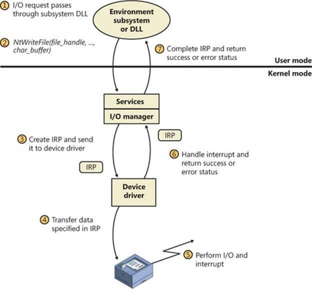
Figure 8-10. Issuing and completing a synchronous I/O request
Now that we’ve seen how an I/O is initiated, let’s take a closer look at interrupt processing and I/O completion.
Servicing an Interrupt
After an I/O device completes a data transfer, it interrupts for service, and the Windows kernel, I/O manager, and device driver are called into action. Figure 8-11 illustrates the first phase of the process. (Chapter 3 in Part 1 describes the interrupt dispatching mechanism, including DPCs. We’ve included a brief recap here because DPCs are key to I/O processing on interrupt-driven devices.)
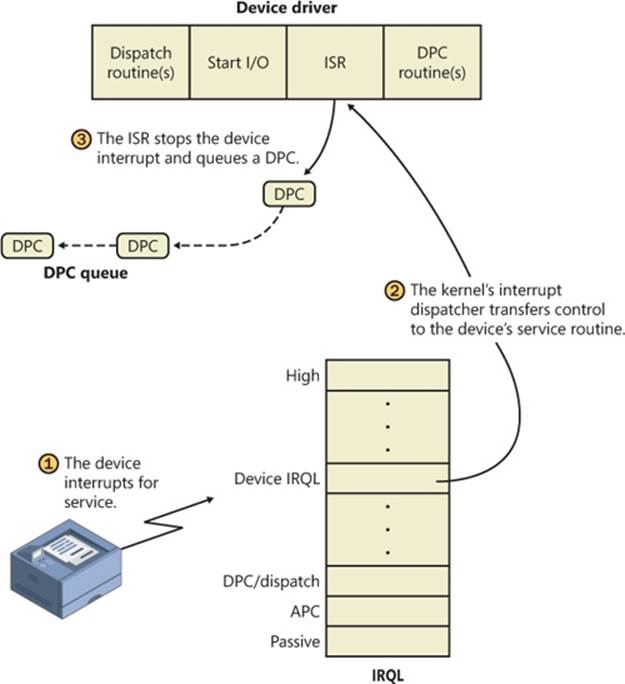
Figure 8-11. Servicing a device interrupt (phase 1)
When a device interrupt occurs, the processor transfers control to the kernel trap handler, which indexes into its interrupt dispatch table to locate the ISR for the device. ISRs in Windows typically handle device interrupts in two steps. When an ISR is first invoked, it usually remains atdevice IRQL only long enough to capture the device status and then stop the device’s interrupt. It then queues a DPC and exits, dismissing the interrupt. Later, when the DPC routine is called at IRQL 2, the device finishes processing the interrupt. When that’s done, the device calls the I/O manager to complete the I/O and dispose of the IRP. It will also start the next I/O request that is waiting in the device queue.
The advantage of using a DPC to perform most of the device servicing is that any blocked interrupt whose IRQL lies between the device IRQL and the DPC/dispatch IRQL (2) is allowed to occur before the lower-priority DPC processing occurs. Intermediate-level interrupts are thus serviced more promptly than they otherwise would be, and this reduces latency on the system. This second phase of an I/O (the DPC processing) is illustrated in Figure 8-12.
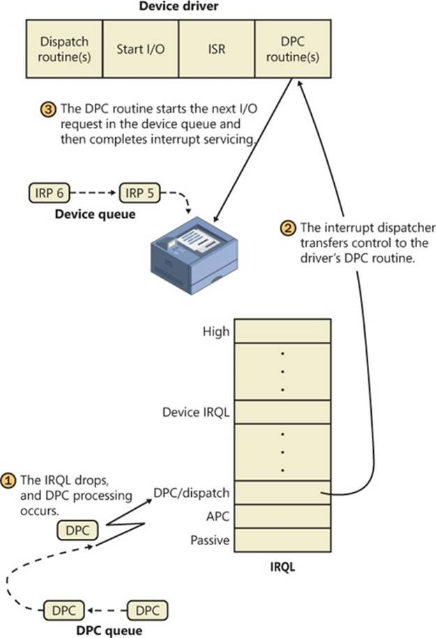
Figure 8-12. Servicing a device interrupt (phase 2)
Completing an I/O Request
After a device driver’s DPC routine has executed, some work still remains before the I/O request can be considered finished. This third stage of I/O processing is called I/O completion and is initiated when a driver calls IoCompleteRequest to inform the I/O manager that it has completed processing the request specified in the IRP (and the stack location that it owns). The steps I/O completion entails vary with different I/O operations. For example, all the I/O drivers record the outcome of the operation in an I/O status block, a data structure stored in the IRP and then copied back into a caller-supplied buffer during I/O completion. Similarly, some drivers that perform buffered I/O require the I/O system to return data to the calling thread.
In both cases, the I/O system must copy data that is stored in system memory into the caller’s virtual address space. If the IRP completed synchronously, the caller’s address space is current and directly accessible, but if the IRP completed asynchronously, the I/O manager must delay IRP completion until it can access the caller’s address space. To gain access to the caller’s virtual address space, the I/O manager must transfer the data “in the context of the caller’s thread”—that is, while the caller’s thread is executing (which implies that the caller’s process is the current process and its address space is mapped on the processor). It does so by queuing a special kernel-mode asynchronous procedure call (APC) to the thread. This process is illustrated in Figure 8-13.
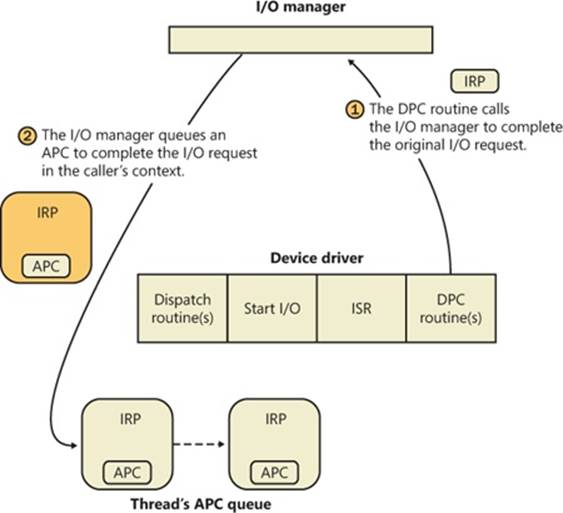
Figure 8-13. Completing an I/O request (phase 1)
As explained in Chapter 3 in Part 1, APCs execute in the context of a particular thread, whereas a DPC executes in arbitrary thread context, meaning that the DPC routine can’t touch the user-mode process address space. Remember too that DPCs have a higher IRQL than APCs.
The next time that the thread begins to execute at low IRQL (below DISPATCH_LEVEL), the pending APC is delivered. The kernel transfers control to the I/O manager’s APC routine, which copies the data (for a read request) and the return status into the original caller’s address space, frees the IRP representing the I/O operation, and either sets the caller’s file handle (and any caller-supplied event) to the signaled state for synchronous I/O or queues an entry to the caller’s I/O completion port. The I/O is now considered complete. The original caller or any other threads that are waiting on the file (or other object) handle are released from their waiting state and readied for execution. Figure 8-14 illustrates the second stage of I/O completion.
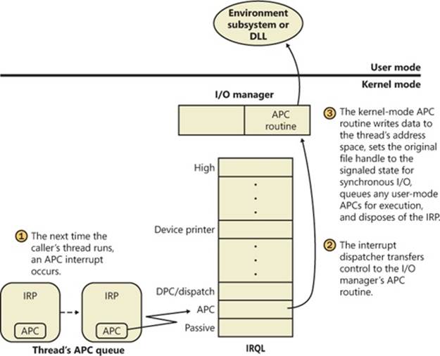
Figure 8-14. Completing an I/O request (phase 2)
Although this is the normal path through which I/O completion occurs, Windows can take a shortcut if the I/O happens to be completed in the same thread that issued the I/O request. In this situation, as long as APC delivery was not disabled (in order to maintain compatibility with legacy versions of Windows, which always used an APC, even in this situation), the phase 2 I/O completion mechanism is called inline.
A final note about I/O completion: the asynchronous I/O functions ReadFileEx and WriteFileEx allow a caller to supply a user-mode APC as a parameter. If the caller does so, the I/O manager queues this APC to the caller’s thread APC queue as the last step of I/O completion. This feature allows a caller to specify a subroutine to be called when an I/O request is completed or canceled. User-mode APC completion routines execute in the context of the requesting thread and are delivered only when the thread enters an alertable wait state (such as calling the Windows SleepEx, WaitForSingleObjectEx, or WaitForMultipleObjectsEx function).
Synchronization
Drivers must synchronize their access to global driver data and hardware registers for two reasons:
§ The execution of a driver can be preempted by higher-priority threads and time-slice (or quantum) expiration or can be interrupted by higher IRQL interrupts.
§ On multiprocessor systems, Windows can run driver code simultaneously on more than one processor.
Without synchronization, corruption could occur—for example, because device driver code running at passive IRQL (0) when a caller initiates an I/O operation can be interrupted by a device interrupt, causing the device driver’s ISR to execute while its own device driver is already running. If the device driver was modifying data that its ISR also modifies, such as device registers, heap storage, or static data, the data can become corrupted when the ISR executes. Figure 8-15 illustrates this problem.
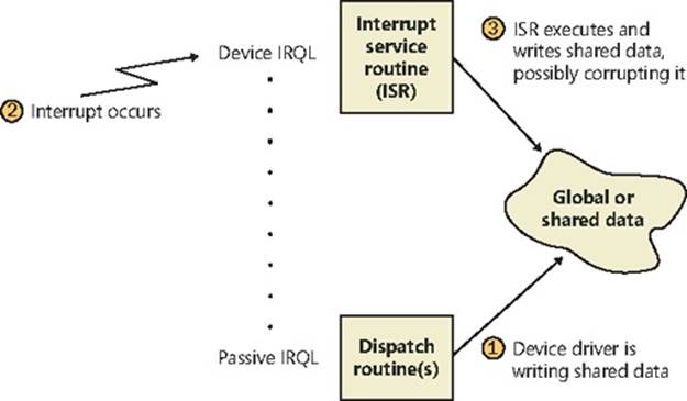
Figure 8-15. Concurrent access to shared data by a device driver dispatch routine and ISR
To avoid this situation, a device driver written for Windows must synchronize its access to any data that can be accessed at more than one IRQL. Before attempting to update shared data, the device driver must lock out all other threads (or CPUs, in the case of a multiprocessor system) to prevent them from updating the same data structure.
The Windows kernel provides a special synchronization routine called KeSynchronizeExecution that device drivers call when they access data that their ISRs also access. This kernel synchronization routine keeps the ISR from executing while the shared data is being accessed. A driver can also use KeAcquireInterruptSpinLock to access an interrupt object’s spinlock directly, although drivers can generally behave better by relying on KeSynchronizeExecution for synchronization with an ISR because calling this function at PASSIVE_LEVEL will synchronize with a KEVENT in the interrupt object structure instead of raising IRQL.
By now, you should realize that although ISRs require special attention, any data that a device driver uses is subject to being accessed by the same device driver running on another processor. Therefore, it’s critical for device driver code to synchronize its use of any global or shared data (or any accesses to the physical device itself). If the ISR uses that data, the device driver must use KeSynchronizeExecution or KeAcquireInterruptSpinLock; otherwise, the device driver can use standard kernel spinlocks (which are acquired at DISPATCH_LEVEL (IRQL 2).
I/O Requests to Layered Drivers
The preceding section showed how an I/O request to a simple device controlled by a single device driver is handled. I/O processing for file-based devices or for requests to other layered drivers happens in much the same way. The major difference is, obviously, that one or more additional layers of processing are added to the model.
Figure 8-16 shows a very simplified, illustrative example of how an asynchronous I/O request might travel through layered drivers. It uses as an example a disk controlled by a file system.
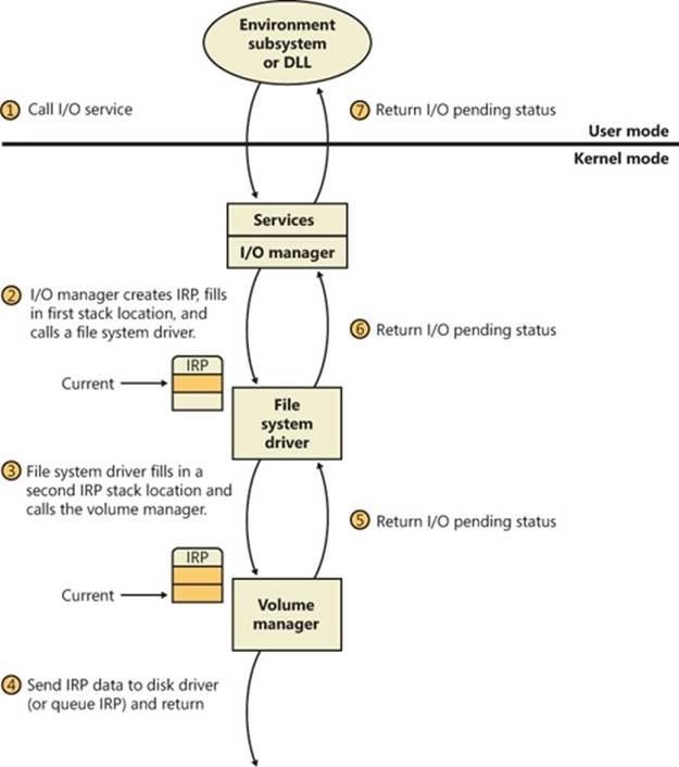
Figure 8-16. Queuing an asynchronous request to layered drivers
Once again, the I/O manager receives the request and creates an I/O request packet to represent it. This time, however, it delivers the packet to a file system driver. The file system driver exercises great control over the I/O operation at that point. Depending on the type of request the caller made, the file system can send the same IRP to the disk driver or it can generate additional IRPs and send them separately to the disk driver.
EXPERIMENT: VIEWING A DEVICE STACK
The kernel debugger command !devstack shows you the device stack of layered device objects associated with a specified device object. This example shows the device stack associated with a device object, \device\keyboardclass0, which is owned by the keyboard class driver:
lkd> !devstack keyboardclass0
!DevObj !DrvObj !DevExt ObjectName
fffffa800a5e2040 \Driver\Ctrl2cap fffffa800a5e2190
> fffffa800a612ce0 \Driver\kbdclass fffffa800a612e30 KeyboardClass0
fffffa800a612040 \Driver\i8042prt fffffa800a612190
fffffa80076e0a00 \Driver\ACPI fffffa80076f3a90 0000005c
!DevNode fffffa800770f750 :
DeviceInst is "ACPI\PNP0303\4&b0a2531&0"
ServiceName is "i8042prt"
The output highlights the entry associated with KeyboardClass0 with the “>” character in column one. The entries above that line are drivers layered above the keyboard class driver, and those below are layered beneath it. In general, IRPs flow from the top of the stack to the bottom.
The file system is most likely to reuse an IRP if the request it receives translates into a single straightforward request to a device. For example, if an application issues a read request for the first 512 bytes in a file stored on a volume, the NTFS file system would simply call the volume manager driver, asking it to read one sector from the volume, beginning at the file’s starting location.
To accommodate its reuse by multiple drivers in a request to layered drivers, an IRP contains a series of IRP stack locations (not to be confused with the CPU stack used by threads to store function parameters and return addresses). These data areas, one for every driver that will be called, contain the information that each driver needs to execute its part of the request—for example, function code, parameters, and driver context information. As Figure 8-16 illustrates, additional stack locations are filled in as the IRP passes from one driver to the next. You can think of an IRP as being similar to a stack in the way data is added to it and removed from it during its lifetime. However, an IRP isn’t associated with any particular process, and its allocated size doesn’t grow or shrink. The I/O manager allocates an IRP from one of its IRP look-aside lists or nonpaged system memory at the beginning of the I/O operation.
NOTE
Since the number of devices on a given stack is known in advance, the I/O manager allocates one stack location per device driver on the stack. However, there are situations in which an IRP might be directed into a new driver stack, as can happen in scenarios involving the Filter Manager, which allows one filter to redirect an IRP to another filter (going from a local file system to a network file system, for example). The I/O manager exposes an API, IoAdjustStackSizeForRedirection, that enables this functionality by adding the required stack locations because of devices present on the redirected stack.
EXPERIMENT: EXAMINING IRPS
In this experiment, you’ll find an uncompleted IRP on the system, and you’ll determine the IRP type, the device at which it’s directed, the driver that manages the device, the thread that issued the IRP, and what process the thread belongs to.
At any point in time, there are at least a few uncompleted IRPs on a system. This occurs because there are many devices to which applications can issue IRPs that a driver will complete only when a particular event occurs, such as data becoming available. One example is a blocking read from a network endpoint. You can see the outstanding IRPs on a system with the !irpfind kernel debugger command:
lkd> !irpfind
Scanning large pool allocation table for Tag: Irp? (86c16000 : 86d16000)
Searching NonPaged pool (80000000 : ffc00000) for Tag: Irp?
Irp [ Thread ] irpStack: (Mj,Mn) DevObj [Driver] MDL Process
862d2380 [8666dc68] irpStack: ( c, 2) 84a6f020 [ \FileSystem\Ntfs]
862d2bb0 [864e3d78] irpStack: ( e,20) 86171348 [ \Driver\AFD] 0x864dbd90
862d4518 [865f7600] irpStack: ( d, 0) 86156328 [ \FileSystem\Npfs]
862d4688 [867133f0] irpStack: ( 3, 0) 86156328 [ \FileSystem\Npfs]
862dd008 [00000000] Irp is complete (CurrentLocation 4 > StackCount 3) 0x00420000
862dee28 [864fc030] irpStack: ( 3, 0) 84baf030 [ \Driver\kbdclass]
The entry in bold in the output describes an IRP that is directed at the Kbdclass driver, so it is likely that the IRP was issued by the Windows subsystem raw input thread that reads keyboard input. Examining the IRP with the !irp command reveals the following:
lkd> !irp 862dee28
Irp is active with 3 stacks 3 is current (= 0x862deee0)
No Mdl: System buffer=864f5108: Thread 864fc030: Irp stack trace.
cmd flg cl Device File Completion-Context
[ 0, 0] 0 0 00000000 00000000 00000000-00000000
Args: 00000000 00000000 00000000 00000000
[ 0, 0] 0 0 00000000 00000000 00000000-00000000
Args: 00000000 00000000 00000000 00000000
>[ 3, 0] 0 1 84baf030 864f52f8 00000000-00000000 pending
\Driver\kbdclass
Args: 00000078 00000000 00000000 00000000
The active stack location is at the bottom. (The debugger shows the active location with a “>” character in column one.) It has a major function of 3, which corresponds to IRP_MJ_READ.
The next step is to see what device object the IRP is targeting by executing the !devobj command on the device object address in the active stack location.
lkd> !devobj 84baf030
Device object (84baf030) is for:
KeyboardClass1 \Driver\kbdclass DriverObject 84b706b8
Current Irp 00000000 RefCount 0 Type 0000000b Flags 00002044
Dacl 8b0538b8 DevExt 84baf0e8 DevObjExt 84baf1c8
ExtensionFlags (0x00000800)
Unknown flags 0x00000800
AttachedTo (Lower) 84badaa0 \Driver\TermDD
Device queue is not busy.
The device at which the IRP is targeted is KeyboardClass1. The presence of a device object owned by the Termdd driver attached beneath it reveals that it is the device that represents keyboard input from a Terminal Server client, not the physical keyboard.
We can see details about the thread and process that issued the IRP by using the !thread and !process commands:
lkd> !thread 864fc030
THREAD 864fc030 Cid 01d4.0234 Teb: 7ffd9000 Win32Thread: ffac4008
WAIT: (WrUserRequest) KernelMode Alertable
8623c620 SynchronizationEvent
864fc3a8 NotificationTimer
864fc378 SynchronizationTimer
864fc360 SynchronizationEvent
IRP List:
86af0e28: (0006,01d8) Flags: 00060970 Mdl: 00000000
86503958: (0006,0268) Flags: 00060970 Mdl: 00000000
862dee28: (0006,01d8) Flags: 00060970 Mdl: 00000000
Not impersonating
DeviceMap 8b0087d8
Owning Process 0 Image: <Unknown>
Attached Process 864d2d90 Image: csrss.exe
Wait Start TickCount 171909 Ticks: 29 (0:00:00:00.452)
Context Switch Count 121222
UserTime 00:00:00.000
KernelTime 00:00:00.717
Win32 Start Address 0x764d9a30
Stack Init 96f46000 Current 96f45c28 Base 96f46000 Limit 96f43000 Call 0
Priority 15 BasePriority 13 PriorityDecrement 0 IoPriority 2 PagePriority 5
lkd> !process 864d2d90
PROCESS 864d2d90 SessionId: 1 Cid: 0208 Peb: 7ffdf000 ParentCid: 0200
DirBase: ce21e0a0 ObjectTable: 964a6e68 HandleCount: 284.
Image: csrss.exe
Locating the thread in Process Explorer by opening the Properties dialog box for Csrss.exe and going to the Threads tab confirms, through the names of the functions on its stack, the role of the thread as a raw input thread for the Windows subsystem:
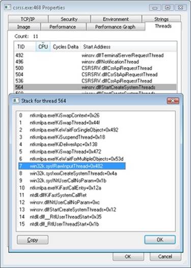
After the disk controller’s DMA adapter finishes a data transfer, the disk controller interrupts the host, causing the ISR for the disk controller to run, which requests a DPC callback completing the IRP, as shown in Figure 8-17.
As an alternative to reusing a single IRP, a file system can establish a group of associated IRPs that work in parallel on a single I/O request. For example, if the data to be read from a file is dispersed across the disk, the file system driver might create several IRPs, each of which reads some portion of the request from a different sector. This queuing is illustrated in Figure 8-18.
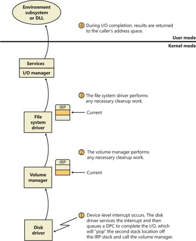
Figure 8-17. Completing a layered I/O request
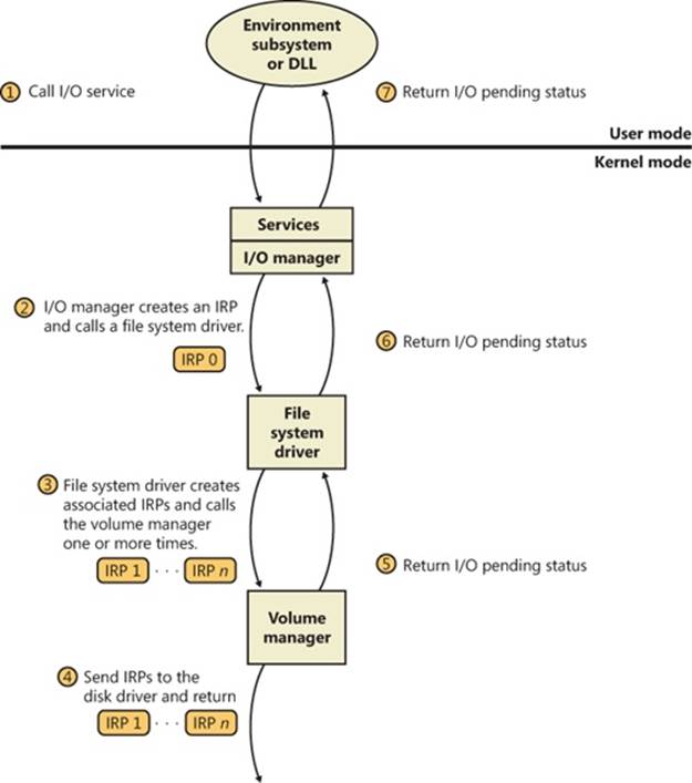
Figure 8-18. Queuing associated IRPs
The file system driver delivers the associated IRPs to the volume manager, which in turn sends them to the disk device driver, which queues them to the disk device. They are processed one at a time, and the file system driver keeps track of the returned data. When all the associated IRPs complete, the I/O system completes the original IRP and returns to the caller, as shown in Figure 8-19.
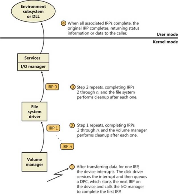
Figure 8-19. Completing associated IRPs
NOTE
All Windows file system drivers that manage disk-based file systems are part of a stack of drivers that is at least three layers deep: the file system driver sits at the top, a volume manager in the middle, and a disk driver at the bottom. In addition, any number of filter drivers can be interspersed above and below these drivers. For clarity, the preceding example of layered I/O requests includes only a file system driver and the volume manager driver. See Chapter 9, on storage management, for more information.
Thread Agnostic I/O
In the I/O models described thus far, IRPs are queued to the thread that initiated the I/O and are completed by the I/O manager issuing an APC to that thread so that process-specific and thread-specific context is accessible by completion processing. Thread-specific I/O processing is usually sufficient for the performance and scalability needs of most applications, but Windows also includes support for thread agnostic I/O via two mechanisms:
§ I/O completion ports, which are described at length later in this chapter
§ Locking the user buffer into memory and mapping it into the system address space
With I/O completion ports, the application decides when it wants to check for the completion of I/O, so the thread that happens to have issued an I/O request is not necessarily relevant because any other thread can perform the completion request. As such, instead of completing the IRP inside the specific thread’s context, it can be completed in the context of any thread that has access to the completion port.
Likewise, with a locked and kernel-mapped version of the user buffer, there’s no need to be in the same memory address space as the issuing thread because the kernel can access the memory from arbitrary contexts. Applications can enable this mechanism by usingSetFileIoOverlappedRange as long as they have the SE_LOCK_MEMORY privilege.
With both completion port I/O and I/O on file buffers set by SetFileIoOverlappedRange, the I/O manager associates the IRPs with the file object to which they have been issued instead of with the issuing thread. The !fileobj extension in WinDbg will show an IRP list for file objects that are used with these mechanisms.
In the next sections, we’ll see how thread agnostic I/O increases the reliability and performance of applications on Windows.
I/O Cancellation
While there are many ways in which IRP processing occurs and various methods to complete an I/O request, a great many I/O processing operations actually end in cancellation rather than completion. For example, a device may require removal while IRPs are still active, or the user might cancel a long-running operation to a device—for example, a network operation. Another situation requiring I/O cancellation support is thread and process termination. When a thread exits, the I/Os associated with the thread must be cancelled because the I/O operations are no longer relevant, and the thread cannot be deleted until the outstanding I/Os have completed.
The Windows I/O manager, working with drivers, must deal with these requests efficiently and reliably to provide a smooth user experience. Drivers manage this need by registering a cancel routine for their cancellable I/O operations (typically, those operations that are still enqueued and not yet in progress), which is invoked by the I/O manager to cancel an I/O operation. When drivers fail to play their role in these scenarios, users may experience unkillable processes, which have disappeared visually but linger and still appear in Task Manager or Process Explorer. (See Chapter 5, “Processes, Threads, and Jobs” in Part 1 for more information on processes and threads.)
User-Initiated I/O Cancellation
Most software uses one thread to handle user interface (UI) input and one or more threads to perform work, including I/O. In some cases, when a user wants to abort an operation that was initiated in the UI, an application might need to cancel outstanding I/O operations. Operations that complete quickly might not require cancellation, but for operations that take arbitrary amounts of time—like large data transfers or network operations—Windows provides support for cancelling both synchronous operations and asynchronous operations. A thread can cancel its own outstanding asynchronous I/Os by calling CancelIo. It can cancel all asynchronous I/Os issued to a specific file handle, regardless of by which thread, in the same process with CancelIoEx. CancelIoEx also works on operations associated with I/O completion ports through the thread-agnostic support in Windows that was mentioned earlier because the I/O system keeps track of a completion port’s outstanding I/Os by linking them with the completion port.
For cancelling synchronous I/Os, a thread can call CancelSynchronousIo. CancelSynchronousIo enables even create (open) operations to be cancelled when supported by a device driver, and several drivers in Windows support this functionality, including the drivers that managenetwork file systems (for example, MUP, DFS, and SMB), which can cancel open operations to network paths. Figures Figure 8-20 and Figure 8-21 show synchronous and asynchronous I/O cancellation. (To a driver, all cancel processing looks the same.)
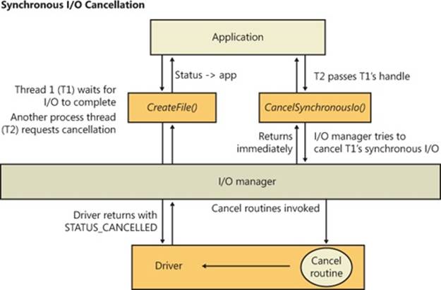
Figure 8-20. Synchronous I/O cancellation
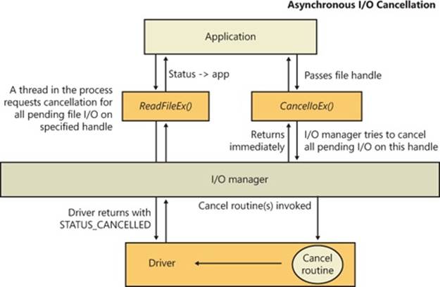
Figure 8-21. Asynchronous I/O cancellation
I/O Cancellation for Thread Termination
The other scenario in which I/Os must be cancelled is when a thread exits, either directly or as the result of its process terminating (which causes the threads of the process to terminate). Because every thread has a list of IRPs associated with it, the I/O manager can walk this list, look for cancellable IRPs, and cancel them. Unlike CancelIoEx, which does not wait for an IRP to be cancelled before returning, the process manager will not allow thread termination to proceed until all I/Os have been cancelled. As a result, if a driver fails to cancel an IRP, the process and thread object will remain allocated until the system shuts down. Figure 8-22 illustrates the process termination scenario.
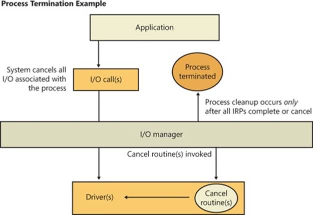
Figure 8-22. Cancellation during process termination
NOTE
Only IRPs for which a driver sets a cancel routine are cancellable. The process manager waits until all I/Os associated with a thread are either cancelled or completed before deleting the thread.
EXPERIMENT: DEBUGGING AN UNKILLABLE PROCESS
In this experiment, we’ll use Notmyfault from Sysinternals (we’ll cover Notmyfault heavily in the “Crash Dump Analysis” section in Chapter 14) to force the unkillable process problem to exhibit itself by causing the Myfault.sys driver (which Notmyfault.exe uses) to indefinitely hold an IRP without having registered a cancel routine for it.
To start, run Notmyfault.exe, select Hang With IRP from the list of options on the Hang tab, and then click the Hang button. The dialog box should look like the following when properly configured.
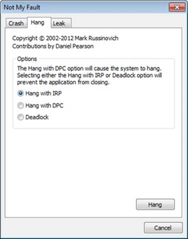
You shouldn’t see anything happen, and you should be able to click the Cancel button to quit the application. However, you should still see the Notmyfault process in Task Manager or Process Explorer. Attempts to terminate the process will fail because Windows will wait forever for the IRP to complete given that the Myfault driver doesn’t register a cancel routine.
To debug an issue such as this, you can use WinDbg to look at what the thread is currently doing. Open a local kernel debugger session, and start by listing the information about the Notmyfault.exe process with the !process command:
lkd> !process 0 7 notmyfault.exe
PROCESS 86843ab0 SessionId: 1 Cid: 0594 Peb: 7ffd8000 ParentCid: 05c8
DirBase: ce21f380 ObjectTable: 9cfb5070 HandleCount: 33.
Image: NotMyfault.exe
VadRoot 86658138 Vads 44 Clone 0 Private 210. Modified 5. Locked 0.
DeviceMap 987545a8
...
THREAD 868139b8 Cid 0594.0230 Teb: 7ffde000 Win32Thread: 00000000
WAIT: (Executive) KernelMode Non-Alertable
86797c64 NotificationEvent
IRP List:
86a51228: (0006,0094) Flags: 00060000 Mdl: 00000000
...
ChildEBP RetAddr Args to Child
88ae4b78 81cf23bf 868139b8 86813a40 00000000 nt!KiSwapContext+0x26
88ae4bbc 81c8fcf8 868139b8 86797c08 86797c64 nt!KiSwapThread+0x44f
88ae4c14 81e8a356 86797c64 00000000 00000000 nt!KeWaitForSingleObject+0x492
88ae4c40 81e875a3 86a51228 86797c08 86a51228 nt!IopCancelAlertedRequest+0x6d
88ae4c64 81e87cba 00000103 86797c08 00000000 nt!IopSynchronousServiceTail+0x267
88ae4d00 81e7198e 86727920 86a51228 00000000 nt!IopXxxControlFile+0x6b7
88ae4d34 81c92a7a 0000007c 00000000 00000000 nt!NtDeviceIoControlFile+0x2a
88ae4d34 77139a94 0000007c 00000000 00000000 nt!KiFastCallEntry+0x12a
01d5fecc 00000000 00000000 00000000 00000000 ntdll!KiFastSystemCallRet
...
From the stack trace, you can see that the thread that initiated the I/O realized that the IRP had been cancelled (IopSynchronousServiceTail called IopCancelAlertedRequest) and is now waiting for the cancellation or completion. The next step is to use the same debugger extension command used in the previous experiments, !irp, and attempt to analyze the problem. Copy the IRP pointer, and examine it with !irp:
lkd> !irp 86a51228
Irp is active with 1 stacks 1 is current (= 0x86a51298)
No Mdl: No System Buffer: Thread 868139b8: Irp stack trace.
cmd flg cl Device File Completion-Context
>[ e, 0] 5 0 86727920 86797c08 00000000-00000000
\Driver\MYFAULT
Args: 00000000 00000000 83360020 00000000
From this output, it is obvious who the culprit driver is: \Driver\MYFAULT, or Myfault.sys. The name of the driver emphasizes that the only way this situation can happen is through a driver problem and not a buggy application. Unfortunately, now that you know which driver caused this issue, there isn’t much you can do—a system reboot is necessary because Windows can never safely assume it is okay to ignore the fact that cancellation hasn’t occurred yet. The IRP could return at any time and cause corruption of system memory. If you encounter this situation in practice, you should check for a newer version of the driver, which might include a fix for the bug.
I/O Completion Ports
Writing a high-performance server application requires implementing an efficient threading model. Having either too few or too many server threads to process client requests can lead to performance problems. For example, if a server creates a single thread to handle all requests, clients can become starved because the server will be tied up processing one request at a time. A single thread could simultaneously process multiple requests, switching from one to another as I/O operations are started, but this architecture introduces significant complexity and can’t take advantage of systems with more than one logical processor. At the other extreme, a server could create a big pool of threads so that virtually every client request is processed by a dedicated thread. This scenario usually leads to thread-thrashing, in which lots of threads wake up, perform some CPU processing, block while waiting for I/O, and then, after request processing is completed, block again waiting for a new request. If nothing else, having too many threads results in excessive context switching, caused by the scheduler having to divide processor time among multiple active threads.
The goal of a server is to incur as few context switches as possible by having its threads avoid unnecessary blocking, while at the same time maximizing parallelism by using multiple threads. The ideal is for there to be a thread actively servicing a client request on every processor and for those threads not to block when they complete a request if additional requests are waiting. For this optimal process to work correctly, however, the application must have a way to activate another thread when a thread processing a client request blocks on I/O (such as when it reads from a file as part of the processing).
The IoCompletion Object
Applications use the IoCompletion executive object, which is exported to the Windows API as a completion port, as the focal point for the completion of I/O associated with multiple file handles. Once a file is associated with a completion port, any asynchronous I/O operations that complete on the file result in a completion packet being queued to the completion port. A thread can wait for any outstanding I/Os to complete on multiple files simply by waiting for a completion packet to be queued to the completion port. The Windows API provides similar functionality with the WaitForMultipleObjects API function, but the advantage that completion ports have is that concurrency, or the number of threads that an application has actively servicing client requests, is controlled with the aid of the system.
When an application creates a completion port, it specifies a concurrency value. This value indicates the maximum number of threads associated with the port that should be running at any given time. As stated earlier, the ideal is to have one thread active at any given time for every processor in the system. Windows uses the concurrency value associated with a port to control how many threads an application has active. If the number of active threads associated with a port equals the concurrency value, a thread that is waiting on the completion port won’t be allowed to run. Instead, it is expected that one of the active threads will finish processing its current request and check to see whether another packet is waiting at the port. If one is, the thread simply grabs the packet and goes off to process it. When this happens, there is no context switch, and the CPUs are utilized nearly to their full capacity.
Using Completion Ports
Figure 8-23 shows a high-level illustration of completion port operation. A completion port is created with a call to the Windows API function CreateIoCompletionPort. Threads that block on a completion port become associated with the port and are awakened in last in, first out (LIFO) order so that the thread that blocked most recently is the one that is given the next packet. Threads that block for long periods of time can have their stacks swapped out to disk, so if there are more threads associated with a port than there is work to process, the in-memory footprints of threads blocked the longest are minimized.
A server application will usually receive client requests via network endpoints that are identified by file handles. Examples include Windows Sockets 2 (Winsock2) sockets or named pipes. As the server creates its communications endpoints, it associates them with a completion port and its threads wait for incoming requests by calling GetQueuedCompletionStatus on the port. When a thread is given a packet from the completion port, it will go off and start processing the request, becoming an active thread. A thread will block many times during its processing, such as when it needs to read or write data to a file on disk or when it synchronizes with other threads. Windows detects this activity and recognizes that the completion port has one less active thread. Therefore, when a thread becomes inactive because it blocks, a thread waiting on thecompletion port will be awakened if there is a packet in the queue.
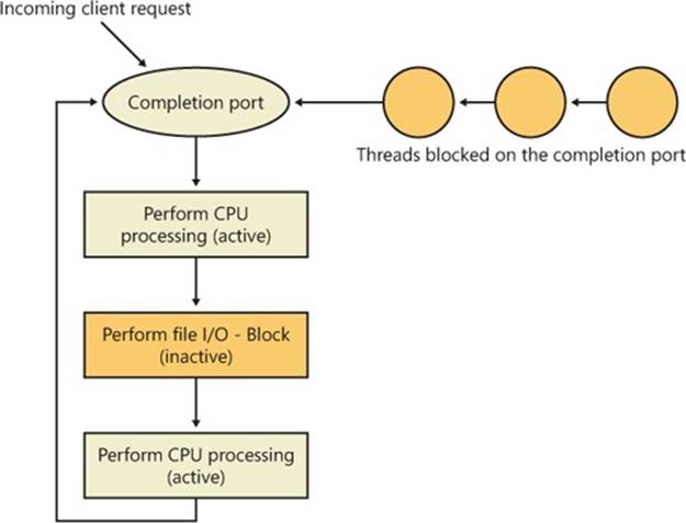
Figure 8-23. I/O completion port operation
Microsoft’s guidelines are to set the concurrency value roughly equal to the number of processors in a system. Keep in mind that it’s possible for the number of active threads for a completion port to exceed the concurrency limit. Consider a case in which the limit is specified as 1. A client request comes in, and a thread is dispatched to process the request, becoming active. A second request arrives, but a second thread waiting on the port isn’t allowed to proceed because the concurrency limit has been reached. Then the first thread blocks waiting for a file I/O, so it becomes inactive. The second thread is then released, and while it’s still active, the first thread’s file I/O is completed, making it active again. At that point—and until one of the threads blocks—the concurrency value is 2, which is higher than the limit of 1. Most of the time, the count of active threads will remain at or just above the concurrency limit.
The completion port API also makes it possible for a server application to queue privately defined completion packets to a completion port by using the PostQueuedCompletionStatus function. A server typically uses this function to inform its threads of external events, such as the need to shut down gracefully.
Applications can use thread agnostic I/O, described earlier, with I/O completion ports to avoid associating threads with their own I/Os and associating them with a completion port object instead. In addition to the other scalability benefits of I/O completion ports, their use can minimize context switches. Standard I/O completions must be executed by the thread that initiated the I/O, but when an I/O associated with an I/O completion port completes, the I/O manager uses any waiting thread to perform the completion operation.
I/O Completion Port Operation
Windows applications create completion ports by calling the Windows API CreateIoCompletionPort and specifying a NULL completion port handle. This results in the execution of the NtCreateIoCompletion system service. The executive’s IoCompletion object contains a kernel synchronization object called a kernel queue. Thus, the system service creates a completion port object and initializes a queue object in the port’s allocated memory. (A pointer to the port also points to the queue object because the queue is at the start of the port memory.) A kernel queue object has a concurrency value that is specified when a thread initializes it, and in this case the value that is used is the one that was passed to CreateIoCompletionPort. KeInitializeQueue is the function that NtCreateIoCompletion calls to initialize a port’s queue object.
When an application calls CreateIoCompletionPort to associate a file handle with a port, the NtSetInformationFile system service is executed with the file handle as the primary parameter. The information class that is set is FileCompletionInformation, and the completion port’s handle and the CompletionKey parameter from CreateIoCompletionPort are the data values. NtSetInformationFile dereferences the file handle to obtain the file object and allocates a completion context data structure.
Finally, NtSetInformationFile sets the CompletionContext field in the file object to point at the context structure. When an asynchronous I/O operation completes on a file object, the I/O manager checks to see whether the CompletionContext field in the file object is non-NULL. If it is, the I/O manager allocates a completion packet and queues it to the completion port by calling KeInsertQueue with the port as the queue on which to insert the packet. (Remember that the completion port object and queue object have the same address.)
When a server thread invokes GetQueuedCompletionStatus, the system service NtRemoveIoCompletion is executed. After validating parameters and translating the completion port handle to a pointer to the port, NtRemoveIoCompletion calls IoRemoveIoCompletion, which eventually calls KeRemoveQueueEx. For high-performance scenarios, it’s possible that multiple I/Os may have been completed, and although the thread will not block, it will still call into the kernel each time to get one item. The GetQueuedCompletionStatus or GetQueuedCompletionStatusExAPI allows applications to retrieve more than one I/O completion status at the same time, reducing the number of user-to-kernel roundtrips and maintaining peak efficiency. Internally, this is implemented through the NtRemoveIoCompletionEx function, which callsIoRemoveIoCompletion with a count of queued items, which is passed on to KeRemoveQueueEx.
As you can see, KeRemoveQueueEx and KeInsertQueue are the engines behind completion ports. They are the functions that determine whether a thread waiting for an I/O completion packet should be activated. Internally, a queue object maintains a count of the current number of active threads and the maximum number of active threads. If the current number equals or exceeds the maximum when a thread calls KeRemoveQueueEx, the thread will be put (in LIFO order) onto a list of threads waiting for a turn to process a completion packet. The list of threads hangs off the queue object. A thread’s control block data structure (KTHREAD) has a pointer in it that references the queue object of a queue that it’s associated with; if the pointer is NULL, the thread isn’t associated with a queue.
Windows keeps track of threads that become inactive because they block on something other than the completion port by relying on the queue pointer in a thread’s control block. The scheduler routines that possibly result in a thread blocking (such as KeWaitForSingleObject, KeDelayExecution-Thread, and so on) check the thread’s queue pointer. If the pointer isn’t NULL, the functions call KiActivateWaiterQueue, a queue-related function that decrements the count of active threads associated with the queue. If the resultant number is less than the maximum and at least one completion packet is in the queue, the thread at the front of the queue’s thread list is awakened and given the oldest packet. Conversely, whenever a thread that is associated with a queue wakes up after blocking, the scheduler executes the functionKiUnwaitThread, which increments the queue’s active count.
Finally, the PostQueuedCompletionStatus Windows API function results in the execution of the NtSetIoCompletion system service. This function simply inserts the specified packet onto the completion port’s queue by using KeInsertQueue.
Figure 8-24 shows an example of a completion port object in operation. Even though two threads are ready to process completion packets, the concurrency value of 1 allows only one thread associated with the completion port to be active, and so the two threads are blocked on the completion port.
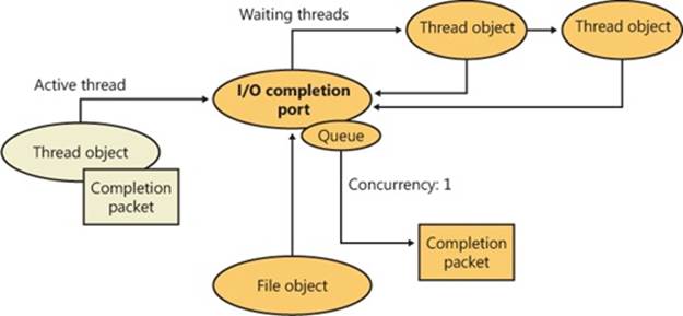
Figure 8-24. I/O completion port operation
Finally, the exact notification model of the I/O completion port can be fine-tuned through the SetFileCompletionNotificationModes API, which allows application developers to take advantage of additional, specific improvements that usually require code changes but can offer even more throughput. Three notification-mode optimizations are supported, which are listed in Table 8-3. Note that these modes are per file handle and permanent.
Table 8-3. I/O Completion Port Notification Modes
|
Notification Mode |
Meaning |
|
Skip completion port onsuccess |
If the following three conditions are true, the I/O manager does not queue a completion entry to the port when it would ordinarily do so. First, a completion port must be associated with the file handle; second, the file must be opened for asynchronous I/O; third, the request must return success immediately without returning ERROR_PENDING. |
|
Skip set event on handle |
The I/O manager does not set the event for the file object if a request returns with a success code or the error returned is ERROR_PENDING and the function that is called is not a synchronous function. If an explicit event is provided for the request, it is still signaled. |
|
Skip set user event on fast I/O |
The I/O manager does not set the explicit event provided for the request if a request takes the fast I/O path and returns with a success code or the error returned is ERROR_PENDING and the function that is called is not a synchronous function. |
I/O Prioritization
Without I/O priority, background activities like search indexing, virus scanning, and disk defragmenting can severely impact the responsiveness of foreground operations. A user launching an application or opening a document while another process is performing disk I/O, for example, experiences delays as the foreground task waits for disk access. The same interference also affects the streaming playback of multimedia content like music from a disk.
Windows includes two types of I/O prioritization to help foreground I/O operations get preference: priority on individual I/O operations and I/O bandwidth reservations.
I/O Priorities
The Windows I/O manager internally includes support for five I/O priorities, as shown in Table 8-4, but only three of the priorities are used. (Future versions of Windows may support High and Low.)
Table 8-4. I/O Priorities
|
I/O Priority |
Usage |
|
Critical |
Memory manager |
|
High |
Not used |
|
Normal |
Normal application I/O |
|
Low |
Not used |
|
Very Low |
Scheduled tasks, Superfetch, defragmenting, content indexing, background activities |
I/O has a default priority of Normal, and the memory manager uses Critical when it wants to write dirty memory data out to disk under low-memory situations to make room in RAM for other data and code. The Windows Task Scheduler sets the I/O priority for tasks that have the default task priority to Very Low. The priority specified by applications that perform background processing is Very Low. All of the Windows background operations, including Windows Defender scanning and desktop search indexing, use Very Low I/O priority.
Prioritization Strategies
Internally, these five I/O priorities are divided into two I/O prioritization modes, called strategies. These are the hierarchy prioritization and the idle prioritization strategies. Hierarchy prioritization deals with all the I/O priorities except Very Low. It implements the following strategy:
§ All critical-priority I/O must be processed before any high-priority I/O.
§ All high-priority I/O must be processed before any normal-priority I/O.
§ All normal-priority I/O must be processed before any low-priority I/O.
§ All low-priority I/O is processed after any higher-priority I/O.
As each application generates I/Os, IRPs are put on different I/O queues based on their priority, and the hierarchy strategy decides the ordering of the operations.
The idle prioritization strategy, on the other hand, uses a separate queue for non-idle priority I/O. Because the system processes all hierarchy prioritized I/O before idle I/O, it’s possible for the I/Os in this queue to be starved, as long as there’s even a single non-idle I/O on the system in the hierarchy priority strategy queue.
To avoid this situation, as well as to control backoff (the sending rate of I/O transfers), the idle strategy uses a timer to monitor the queue and guarantee that at least one I/O is processed per unit of time (typically, half a second). Data written using non-idle I/O priority also causes the cache manager to write modifications to disk immediately instead of doing it later and to bypass its read-ahead logic for read operations that would otherwise preemptively read from the file being accessed. The prioritization strategy also waits for 50 milliseconds after the completion of the last non-idle I/O in order to issue the next idle I/O. Otherwise, idle I/Os would occur in the middle of non-idle streams, causing costly seeks.
Combining these strategies into a virtual global I/O queue for demonstration purposes, a snapshot of this queue might look similar to Figure 8-25. Note that within each queue, the ordering is first-in, first-out (FIFO). The order in the figure is shown only as an example.

Figure 8-25. Sample entries in a global I/O queue
User-mode applications can set I/O priority on three different objects. SetPriorityClass and SetThreadPriority set the priority for all the I/Os that either the entire process or specific threads will generate (the priority is stored in the IRP of each request). SetFileInformationByHandlecan set the priority for a specific file object (the priority is stored in the file object). Drivers can also set I/O priority directly on an IRP by using the IoSetIoPriorityHint API.
NOTE
The I/O priority field in the IRP and/or file object is a hint. There is no guarantee that the I/O priority will be respected or even supported by the different drivers that are part of the storage stack.
The two prioritization strategies are implemented by two different types of drivers. The hierarchy strategy is implemented by the storage port drivers, which are responsible for all I/Os on a specific port, such as ATA, SCSI, or USB. Only the ATA port driver (%SystemRoot%\System32\Ataport.sys) and USB port driver (%SystemRoot%\System32\Usbstor.sys) implement this strategy, while the SCSI and storage port drivers (%SystemRoot%\System32\Scsiport.sys and %SystemRoot%\System32\Stor port.sys) do not.
NOTE
All port drivers check specifically for Critical priority I/Os and move them ahead of their queues, even if they do not support the full hierarchy mechanism. This mechanism is in place to support critical memory manager paging I/Os to ensure system reliability.
This means that consumer mass storage devices such as IDE or SATA hard drives and USB flash disks will take advantage of I/O prioritization, while devices based on SCSI, Fibre Channel, and iSCSI will not.
On the other hand, it is the system storage class device driver (%SystemRoot%\System32\Class pnp.sys) that enforces the idle strategy, so it automatically applies to I/Os directed at all storage devices, including SCSI drives. This separation ensures that idle I/Os will be subject to back-off algorithms to ensure a reliable system during operation under high idle I/O usage and so that applications that use them can make forward progress. Placing support for this strategy in the Microsoft-provided class driver avoids performance problems that would have been caused by lack of support for it in legacy third-party port drivers.
Figure 8-26 displays a simplified view of the storage stack and where each strategy is implemented. See Chapter 9 for more information on the storage stack.
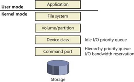
Figure 8-26. Implementation of I/O prioritization across the storage stack
I/O Priority Inversion Avoidance (I/O Priority Inheritance)
To avoid I/O priority inversion (in which a high-I/O-priority thread can be starved by a low-I/O-priority thread), the executive resource (ERESOURCE) locking functionality utilizes several strategies. The ERESOURCE was picked for the implementation of I/O priority inheritance particularly because of its heavy use in file system and storage drivers, where most I/O priority inversion issues can appear.
If an ERESOURCE is being acquired by a thread with low I/O priority, and there are currently waiters on the ERESOURCE with normal or higher priority, the current thread is temporarily boosted to normal I/O priority by using the PsBoostThreadIo API, which increments theIoBoostCount in the ETHREAD structure.
It then calls the IoBoostThreadIoPriority API, which enumerates all the IRPs queued to the target thread (recall that each thread has a list of pending IRPs) and checks which ones have a lower priority than the target priority (normal in this case), thus identifying pending idle I/O priority IRPs. In turn, the device object responsible for each of those IRPs is identified, and the I/O manager checks whether a priority callback has been registered, which driver developers can do through the IoRegisterPriorityCallback API and by setting theDO_PRIORITY_CALLBACK_ENABLED flag on their device object. Depending on whether the IRP was a paging I/O, this mechanism is called the threaded boost or the paging boost.
Finally, if no matching IRPs were found, but the thread has at least some pending IRPs, all are boosted regardless of device object or priority, which is called blanket boosting.
I/O Priority Boosts and Bumps
A few other subtle modifications to normal I/O paths are used by Windows to avoid starvation, inversion, or otherwise unwanted scenarios when I/O priority is being used. Typically, these modifications are done by boosting I/O priority when needed. The following scenarios exhibit this behavior.
§ When a driver is being called with an IRP targeted to a particular file object, Windows makes sure that if the request comes from kernel mode, the IRP uses normal priority even if the file object has a lower I/O priority hint. This is called the kernel bump.
§ When reads or writes to the paging file are occurring (through IoPageRead and IoPageWrite), Windows checks whether the request comes from kernel mode and is not being performed on behalf of Superfetch (which always uses idle I/O). In this case, the IRP uses normal priority even if the current thread has a lower I/O priority. This is called the paging bump.
The following experiment will show you an example of Very Low I/O priority and how you can use Process Monitor to look at I/O priorities on different requests.
EXPERIMENT: VERY LOW VS. NORMAL I/O THROUGHPUT
You can use the IO Priority sample application (included in the book’s utilities) to look at the throughput difference between two threads with different I/O priorities. Launch IoPriority.exe, make sure Thread 1 is checked to use Low priority, and then click the Start IO button. You should notice a significant difference in speed between the two threads, as shown in the following screen.
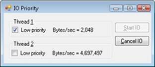
You should also notice that Thread 1’s throughput remains fairly constant, around 2 KB/s. This can easily be explained by the fact that IO Priority performs its I/Os at 2 KB/s, which means that the idle prioritization strategy is kicking in and guaranteeing at least one I/O each half-second. Otherwise, Thread 2 would starve any I/O that Thread 1 is attempting to make.
Note that if both threads run at low priority and the system is relatively idle, their throughput will be roughly equal to the throughput of a single normal I/O priority in the example. This is because low priority I/Os are not artificially throttled or otherwise hindered if there isn’t any competition from higher priority I/O.
You can also use Process Monitor to trace IO Priority’s I/Os and look at their I/O priority hint. Launch Process Monitor, configure a filter for IoPriority.exe, and repeat the experiment. In this application, Thread 1 writes to File_1, and Thread 2 writes to File_2. Scroll down until you see a write to File_1, and you should see output similar to that shown next.
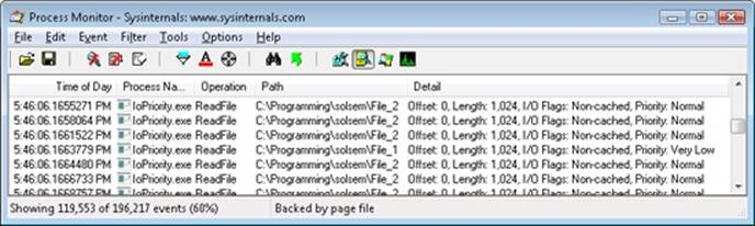
You can see that I/Os directed at File_1 have a priority of Very Low. By looking at the Time Of Day column, you’ll also notice that the I/Os are spaced 0.5 second from each other—another sign of the idle strategy in action.
Finally, by using Process Explorer, you can identify Thread 1 in the IoPriority process by looking at the I/O priority for each of its threads on the Threads tab of its process Properties dialog box. You can also see that the priority for the thread is lower than the default of 8 (normal), which indicates that the thread is probably running in background priority mode. The following screen shot shows what you should expect to see.
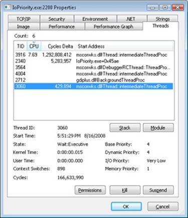
Note that if IO Priority sets the priority on File_1 instead of on the issuing thread, both threads would look the same. Only Process Monitor could show you the difference in I/O priorities.
EXPERIMENT: PERFORMANCE ANALYSIS OF I/O PRIORITY BOOSTING/BUMPING
The kernel exposes several internal variables that can be queried through the undocumented SystemLowPriorityIoInformation system class available in NtQuerySystemInformation. However, even without writing or relying on such an application, you can use the local kernel debugger for viewing these numbers on your system. The following variables are available:
§ IoLowPriorityReadOperationCount and IoLowPriorityWriteOperationCount
§ IoKernelIssuedIoBoostedCount
§ IoPagingReadLowPriorityCount and IoPagingWriteLowPriorityCount
§ IoPagingReadLowPriorityBumpedCount and IoPagingWriteHighPriorityBumpedCount
§ IoBoostedThreadedIrpCount and IoBoostedPagingIrpCount
§ IoBlanketBoostCount
You can use the dd memory-dumping command in the kernel debugger to see the values of these variables.
Bandwidth Reservation (Scheduled File I/O)
Windows I/O bandwidth reservation support is useful for applications that desire consistent I/O throughput. Using the SetFileBandwidthReservation call, a media player application asks the I/O system to guarantee it the ability to read data from a device at a specified rate. If the device can deliver data at the requested rate and existing reservations allow it, the I/O system gives the application guidance as to how fast it should issue I/Os and how large the I/Os should be.
The I/O system won’t service other I/Os unless it can satisfy the requirements of applications that have made reservations on the target storage device. Figure 8-27 shows a conceptual timeline of I/Os issued on the same file. The shaded regions are the only ones that will be available to other applications. If I/O bandwidth is already taken, new I/Os will have to wait until the next cycle.
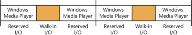
Figure 8-27. Effect of I/O requests during bandwidth reservation
Like the hierarchy prioritization strategy, bandwidth reservation is implemented at the port driver level, which means it is available only for IDE, SATA, or USB-based mass-storage devices.
Container Notifications
Container notifications are specific classes of events that drivers can register for through an asynchronous callback mechanism by using the IoRegisterContainerNotification API and selecting the notification class that interests them. Thus far, one class is implemented in Windows, which is the IoSessionStateNotification class. This class allows drivers to have their registered callback invoked whenever a change in the state of a given session is registered. The following changes are supported:
§ A session is created or terminated
§ A user connects to or disconnects from a session
§ A user logs on to or logs off from a session
By specifying a device object that belongs to a specific session, the driver callback will be active only for that session, while by specifying a global device object (or no device object at all), the driver will receive notifications for all events on a system. This feature is particularly useful for devices that participate in the Plug and Play device redirection functionality that is provided through Terminal Services, which allows a remote device to be visible on the connecting host’s Plug and Play manager bus as well (such as audio or printer device redirection). Once the user disconnects from a session with audio playback, for example, the device driver needs a notification in order to stop redirecting the source audio stream.
Driver Verifier
Driver Verifier is a mechanism that can be used to help find and isolate common bugs in device drivers or other kernel-mode system code. Microsoft uses Driver Verifier to check its own device drivers as well as all device drivers that vendors submit for Windows Hardware Quality Labs (WHQL) testing. Doing so ensures that the drivers submitted are compatible with Windows and free from common driver errors. (Although not described in this book, there is also a corresponding Application Verifier tool that has resulted in quality improvements for user-mode code in Windows.)
Also, although Driver Verifier serves primarily as a tool to help device driver developers discover bugs in their code, it is also a powerful tool for system administrators experiencing crashes. Chapter 14 describes its role in crash analysis troubleshooting.
Driver Verifier consists of support in several system components: the memory manager, I/O manager, and HAL all have driver verification options that can be enabled. These options are configured using the Driver Verifier Manager (%SystemRoot%\System32\Verifier.exe). When you run Driver Verifier with no command-line arguments, it presents a wizard-style interface, as shown in Figure 8-28.
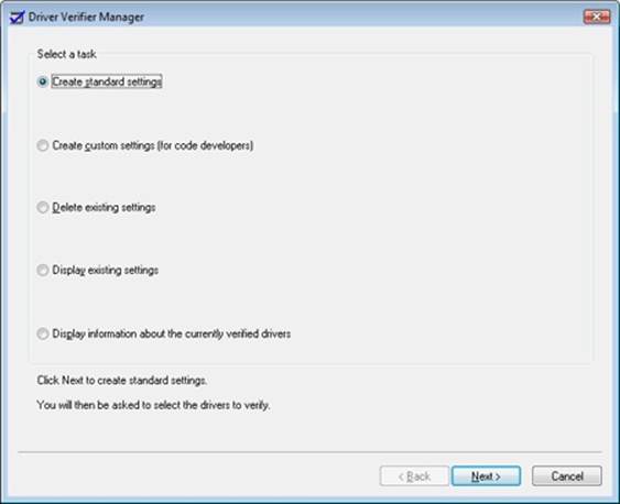
Figure 8-28. Driver Verifier Manager
You can also enable and disable Driver Verifier, as well as display current settings, by using its command-line interface. From a command prompt, type verifier /? to see the switches.
Even when you don’t select any options, Driver Verifier monitors drivers selected for verification, looking for a number of illegal and boundary operations, including calling kernel-memory pool functions at invalid IRQL, double-freeing memory, allocating synchronization objects from NonPagedPoolSession memory, referencing a freed object, delaying shutdown for longer than 20 minutes, and requesting a zero-size memory allocation.
What follows is a description of the I/O-related verification options (shown in Figure 8-29). The options related to memory management are described in Chapter 10, along with how the memory manager redirects a driver’s operating system calls to special verifier versions.
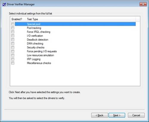
Figure 8-29. Driver Verifier I/O-related options
These options have the following effects:
§ I/O Verification When this option is selected, the I/O manager allocates IRPs for verified drivers from a special pool and their usage is tracked. In addition, the Verifier crashes the system when an IRP is completed that contains an invalid status or when an invalid device object is passed to the I/O manager. This option also monitors all IRPs to ensure that drivers mark them correctly when completing them asynchronously, that they manage device-stack locations correctly, and that they delete device objects only once. In addition, the Verifier randomly stresses drivers by sending them fake power management and WMI IRPs, changing the order in which devices are enumerated, and adjusting the status of PnP and power IRPs when they complete to test for drivers that return incorrect status from their dispatch routines. Finally, Verifier also detects incorrect re-initialization of remove locks while they are still being held due to pending device removal.
§ DMA Checking DMA (direct access memory) is a hardware-supported mechanism that allows devices to transfer data to or from physical memory without involving the CPU. The I/O manager provides a number of functions that drivers use to initiate and control DMA operations, and this option enables checks for correct use of the functions and buffers that the I/O manager supplies for DMA operations.
§ Force Pending I/O Requests For many devices, asynchronous I/Os complete immediately, so drivers may not be coded to properly handle the occasional asynchronous I/O. When this option is enabled, the I/O manager will randomly return STATUS_PENDING in response to a driver’s calls to IoCallDriver, which simulates the asynchronous completion of an I/O.
§ IRP Logging This option monitors a driver’s use of IRPs and makes a record of IRP usage, which is stored as WMI information. You can then use the Dc2wmiparser.exe utility in the WDK to convert these WMI records to a text file. Note that only 20 IRPs for each device will be recorded—each subsequent IRP will overwrite the entry added least recently. After a reboot, this information is discarded, so Dc2wmiparser.exe should be run if the contents of the trace are to be analyzed later.
Kernel-Mode Driver Framework (KMDF)
We’ve already discussed some details about the Windows Driver Foundation (WDF) in Chapter 2, “System Architecture,” in Part 1. In this section, we’ll take a deeper look at the components and functionality provided by the kernel-mode part of the framework, KMDF. Note that this section will only briefly touch on some of the core architecture of KMDF. For a much more complete overview on the subject, please refer to http://msdn.microsoft.com/en-us/library/windows/hardware/gg463370.aspx.
Structure and Operation of a KMDF Driver
First, let’s take a look at which kinds of drivers or devices are supported by KMDF. In general, any WDM-conformant driver should be supported by KMDF, as long as it performs standard I/O processing and IRP manipulation. KMDF is not suitable for drivers that don’t use theWindows kernel API directly but instead perform library calls into existing port and class drivers. These types of drivers cannot use KMDF because they only provide callbacks for the actual WDM drivers that do the I/O processing. Additionally, if a driver provides its own dispatch functions instead of relying on a port or class driver, IEEE 1394 and ISA, PCI, PCMCIA, and SD Client (for Secure Digital storage devices) drivers can also make use of KMDF.
Although KMDF provides an abstraction on top of WDM, the basic driver structure shown earlier also generally applies to KMDF drivers. At their core, KMDF drivers must have the following functions:
§ An initialization routine Just like any other driver, a KMDF driver has a DriverEntry function that initializes the driver. KMDF drivers will initiate the framework at this point and perform any configuration and initialization steps that are part of the driver or part of describing the driver to the framework. For non–Plug and Play drivers, this is where the first device object should be created.
§ An add-device routine KMDF driver operation is based on events and callbacks (described shortly), and the EvtDriverDeviceAdd callback is the single most important one for PnP devices because it receives notifications when the PnP manager in the kernel enumerates one of thedriver’s devices.
§ One or more EvtIo* routines Just like a WDM driver’s dispatch routines, these callback routines handle specific types of I/O requests from a particular device queue. A driver typically creates one or more queues in which KMDF places I/O requests for the driver’s devices. These queues can be configured by request type and dispatching type.
The simplest KMDF driver might need to have only an initialization and add-device routine because the framework will provide the default, generic functionality that’s required for most types of I/O processing, including power and Plug and Play events. In the KMDF model, eventsrefer to run-time states to which a driver can respond or during which a driver can participate. These events are not related to the synchronization primitives (synchronization is discussed in Chapter 3 in Part 1), but are internal to the framework.
For events that are critical to a driver’s operation, or which need specialized processing, the driver registers a given callback routine to handle this event. In other cases, a driver can allow KMDF to perform a default, generic action instead. For example, during an eject event (EvtDeviceEject), a driver can choose to support ejection and supply a callback or to fall back to the default KMDF code that will tell the user that the device is not ejectable. Not all events have a default behavior, however, and callbacks must be provided by the driver. One notable example is the EvtDriverDeviceAdd event that is at the core of any Plug and Play driver.
EXPERIMENT: DISPLAYING KMDF DRIVERS
The Wdfkd.dll extension that ships with the Debugging Tools for Windows package provides many commands that can be used to debug and analyze KMDF drivers and devices (instead of using the built-in WDM-style debugging extension that may not offer the same kind of WDF-specific information). You can display installed KMDF drivers with the !wdfkd.wdfldr debugger command. In the following example, the output from a typical Windows computer is shown, displaying the built-in drivers that are installed.
lkd> !wdfkd.wdfldr
LoadedModuleList 0xfffff880010682d8
----------------------------------
LIBRARY_MODULE fffffa8002776120
Version v1.9 build(7600)
Service \Registry\Machine\System\CurrentControlSet\Services\Wdf01000
ImageName Wdf01000.sys
ImageAddress 0xfffff88000c00000
ImageSize 0xa4000
Associated Clients: 16
ImageName Version WdfGlobals FxGlobals ImageAddress
ImageSize
peauth.sys v1.7(6001) 0xfffffa8004754210 0xfffffa80047540c0 0xfffff880074cc000
0x000a6000
scfilter.sys v1.5(6000) 0xfffffa8002ef34e0 0xfffffa8002ef3390 0xfffff880040b3000
0x0000e000
WinUSB.sys v1.9(7600) 0xfffffa8002eefd20 0xfffffa8002eefbd0 0xfffff88004000000
0x00011000
monitor.sys v1.9(7600) 0xfffffa8004854a10 0xfffffa80048548c0 0xfffff8800412a000
0x0000e000
vmswitch.sys v1.5(6000) 0xfffffa8002de5d60 0xfffffa8002de5c10 0xfffff88003e9b000
0x00068000
vmbus.sys v1.5(6000) 0xfffffa8002d7fcf0 0xfffffa8002d7fba0 0xfffff88003e5f000
0x0003c000
Vid.sys v1.5(6000) 0xfffffa8002ddacf0 0xfffffa8002ddaba0 0xfffff88002a00000
0x00033000
umbus.sys v1.9(7600) 0xfffffa8002e57e70 0xfffffa8002e57d20 0xfffff880035db000
0x00012000
storvsp.sys v1.5(6000) 0xfffffa8002e48b10 0xfffffa8002e489c0 0xfffff88003575000
0x00023000
CompositeBus.sys v1.9(7600) 0xfffffa8002d79160 0xfffffa8002d79010 0xfffff88002936000
0x00010000
HDAudBus.sys v1.7(6001) 0xfffffa8002e357f0 0xfffffa8002e356a0 0xfffff880037a9000
0x00024000
intelppm.sys v1.9(7600) 0xfffffa8002c518f0 0xfffffa8002c517a0 0xfffff880027e7000
0x00016000
cdrom.sys v1.9(7600) 0xfffffa80028bf8f0 0xfffffa80028bf7a0 0xfffff880011c4000
0x0002a000
vmstorfl.sys v1.5(6000) 0xfffffa8002b2cdd0 0xfffffa8002b2cc80 0xfffff8800144a000
0x00010000
vdrvroot.sys v1.9(7600) 0xfffffa80027887c0 0xfffffa8002788670 0xfffff8800139c000
0x0000d000
msisadrv.sys v1.9(7600) 0xfffffa80029c5430 0xfffffa80029c52e0 0xfffff8800135f000
0x0000a000
----------------------------------
Total: 1 library loaded
KMDF Data Model
The KMDF data model is object-based, much like the model for the kernel, but it does not make use of the object manager. Instead, KMDF manages its own objects internally, exposing them as handles to drivers and keeping the actual data structures opaque. For each object type, the framework provides routines to perform operations on the object, such as WdfDeviceCreate, which creates a device. Additionally, objects can have specific data fields or members that can be accessed by Get/Set (used for modifications that should never fail) or Assign/Retrieve APIs (used for modifications that can fail). For example, the WdfInterruptGetInfo function returns information on a given interrupt object (WDFINTERRUPT).
Also unlike the implementation of kernel objects, which all refer to distinct and isolated object types, KMDF objects are all part of a hierarchy—most object types are bound to a parent. The root object is the WDFDRIVER structure, which describes the actual driver. The structure and meaning is analogous to the DRIVER_OBJECT structure provided by the I/O manager, and all other KMDF structures are children of it. The next most important object is WDFDEVICE, which refers to a given instance of a detected device on the system, which must have been created with WdfDeviceCreate. Again, this is analogous to the DEVICE_OBJECT structure that’s used in the WDM model and by the I/O manager. Table 8-5 lists the object types supported by KMDF.
Table 8-5. KMDF Object Types
|
Object |
Type |
Description |
|
Child List |
WDFCHILDLIST |
List of child WDFDEVICE objects associated with the device. Only used by bus drivers. |
|
Collection |
WDFCOLLECTION |
List of objects of a similar type, such as a group of WDFDEVICE objects being filtered. |
|
Deferred Procedure Call |
WDFDPC |
Instance of a DPC object (see Chapter 3 in Part 1 for more information on DPCs). |
|
Device |
WDFDEVICE |
Instance of a device. |
|
DMA Common Buffer |
WDFCOMMONBUFFER |
Region of memory that a device and driver can access for direct memory access (DMA). |
|
DMA Enabler |
WDFDMAENABLER |
Enables DMA on a given channel for a driver. |
|
DMA Transaction |
WDFDMATRANSACTION |
Instance of a DMA transaction. |
|
Driver |
WDFDRIVER |
Root object for the driver; represents the driver, its parameters, and its callbacks, among other items. |
|
File |
WDFFILEOBJECT |
Instance of a file object that can be used as a channel for communication between an application and the driver. |
|
Generic Object |
WDFOBJECT |
Allows driver-defined custom data to be wrapped inside the framework’s object data model as an object. |
|
Interrupt |
WDFINTERRUPT |
Instance of an interrupt that the driver must handle. |
|
I/O Queue |
WDFQUEUE |
Represents a given I/O queue. |
|
I/O Request |
WDFREQUEST |
Represents a given request on a WDFQUEUE. |
|
I/O Target |
WDFIOTARGET |
Represents the device stack being targeted by a given WDFREQUEST. |
|
Look-Aside List |
WDFLOOKASIDE |
Describes an executive look-aside list. |
|
Memory |
WDFMEMORY |
Describes a region of paged or nonpaged pool. |
|
Registry Key |
WDFKEY |
Describes a registry key. |
|
Resource List |
WDFCMRESLIST |
Identifies the hardware resources assigned to a WDFDEVICE. |
|
Resource Range List |
WDFIORESLIST |
Identifies a given possible hardware resource range for a WDFDEVICE. |
|
Resource Requirements List |
WDFIORESREQLIST |
Contains an array of WDFIORESLIST objects describing all possible resource ranges for a WDFDEVICE. |
|
Spinlock |
WDFSPINLOCK |
Describes a spinlock (see Chapter 3 in Part 1 for more information). |
|
String |
WDFSTRING |
Describes a Unicode string structure. |
|
Timer |
WDFTIMER |
Describes an executive timer (see Chapter 3 in Part 1 for more information). |
|
USB Device |
WDFUSBDEVICE |
Identifies the one instance of a USB device. |
|
USB Interface |
WDFUSBINTERFACE |
Identifies one interface on the given WDFUSBDEVICE. |
|
USB Pipe |
WDFUSBPIPE |
Identifies a pipe to an endpoint on a given WDFUSBINTERFACE. |
|
Wait Lock |
WDFWAITLOCK |
Represents a kernel dispatcher event object. |
|
WMI Instance |
WDFWMIINSTANCE |
Represents a WMI data block for a given WDFWMIPROVIDER. |
|
WMI Provider |
WDFWMIPROVIDER |
Describes the WMI schema for all the WDFWMIINSTANCE objects supported by the driver. |
|
Work Item |
WDFWORKITEM |
Describes an executive work item. |
For each of these objects, other KMDF objects can be attached as children—some objects have only one or two valid parents, while other objects can be attached to any parent. For example, a WDFINTERRUPT object must be associated with a given WDFDEVICE, but a WDFSPINLOCK or WDFSTRING can have any object as a parent, allowing fine-grained control over their validity and usage and reducing global state variables. Figure 8-30 shows the entire KMDF object hierarchy.
Note that the associations mentioned earlier and shown in the figure are not necessarily immediate. The parent must simply be on the hierarchy chain, meaning one of the ancestor nodes must be of this type. This relationship is useful to implement because object hierarchies affect not only the objects’ locality but also their lifetime. Each time a child object is created, a reference count is added to it by its link to its parent. Therefore, when a parent object is destroyed, all the child objects are also destroyed, which is why associating objects such as WDFSTRING or WDFMEMORY with a given object, instead of the default WDFDRIVER object, can automatically free up memory and state information when the parent object is destroyed.
Closely related to the concept hierarchy is KMDF’s notion of object context. Because KMDF objects are opaque, as discussed, and are associated with a parent object for locality, it becomes important to allow drivers to attach their own data to an object in order to track certain specific information outside the framework’s capabilities or support.
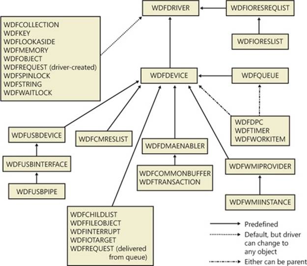
Figure 8-30. KMDF object hierarchy
Object contexts allow all KMDF objects to contain such information, and they additionally allow multiple object context areas, which permit multiple layers of code inside the same driver to interact with the same object in different ways. In the WDM model, the device extension datastructure allows such information to be associated with a given device, but with KMDF even a spinlock or string can contain context areas. This extensibility allows each library or layer of code responsible for processing an I/O to interact independently of other code, based on the context area that it works with, and allows a mechanism similar to inheritance.
Finally, KMDF objects are also associated with a set of attributes that are shown in Table 8-6. These attributes are usually configured to their defaults, but the values can be overridden by the driver when creating the object by specifying a WDF_OBJECT_ATTRIBUTES structure (similar to the object manager’s OBJECT_ATTRIBUTES structure that’s used when creating a kernel object).
Table 8-6. KMDF Object Attributes
|
Attribute |
Description |
|
ContextSizeOverride |
Size of the object context area. |
|
ContextTypeInfo |
Type of the object context area. |
|
EvtCleanupCallback |
Callback to notify the driver of the object’s cleanup before deletion (references may still exist). |
|
EvtDestroyCallback |
Callback to notify the driver of the object’s imminent deletion (reference count will be 0). |
|
ExecutionLevel |
Describes the maximum IRQL at which the callbacks may be invoked by KMDF. |
|
ParentObject |
Identifies the parent of this object. |
|
Size |
Size of the object. |
|
SynchronizationScope |
Specifies whether callbacks should be synchronized with the parent, a queue or device, or nothing. |
KMDF I/O Model
The KMDF I/O model follows the WDM mechanisms discussed earlier in the chapter. In fact, one can even think of the framework itself as a WDM driver, since it uses kernel APIs and WDM behavior to abstract KMDF and make it functional. Under KMDF, the framework driver sets its own WDM-style IRP dispatch routines and takes control over all IRPs sent to the driver. After being handled by one of three KMDF I/O handlers (which we’ll describe shortly), it then packages these requests in the appropriate KMDF objects, inserts them in the appropriate queues if required, and performs driver callback if the driver is interested in those events. Figure 8-31 describes the flow of I/O in the framework.
Based on the IRP processing discussed for WDM drivers earlier, KMDF performs one of the following three actions:
§ Sends the IRP to the I/O handler, which processes standard device operations
§ Sends the IRP to the PnP and power handler that processes these kinds of events and notifies other drivers if the state has changed
§ Sends the IRP to the WMI handler, which handles tracing and logging.
These components will then notify the driver of any events it registered for, potentially forward the request to another handler for further processing, and then complete the request based on an internal handler action or as the result of a driver call. If KMDF has finished processing the IRP but the request itself has still not been fully processed, KMDF will take one of the following actions:
§ For bus drivers and function drivers, complete the IRP with STATUS_INVALID_DEVICE_REQUEST
§ For filter drivers, forward the request to the next lower driver
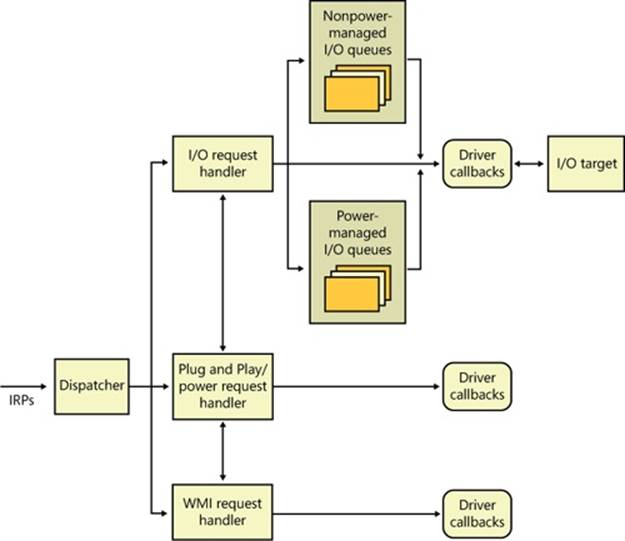
Figure 8-31. KMDF I/O flow and IRP processing
I/O processing by KMDF is based on the mechanism of queues (WDFQUEUE, not the KQUEUE object discussed in the earlier section on I/O completion and in Chapter 3 in Part 1). KMDF queues are highly scalable containers of I/O requests (packaged as WDFREQUEST objects) and provide a rich feature set beyond merely sorting the pending I/Os for a given device. For example, queues also track currently active requests and support I/O cancellation, I/O concurrency (the ability to perform and complete more than one I/O request at a time), and I/Osynchronization (as noted in the list of object attributes in Table 8-6). A typical KMDF driver creates at least one queue (if not more) and associates one or more events with each queue, as well as some of the following options:
§ The callbacks registered with the events associated with this queue.
§ The power management state for the queue. KMDF supports both power-managed and nonpower-managed queues. For the former, the I/O handler will handle waking up the device when required (and when possible), arm the idle timer when the device has no I/Os queued up, and call the driver’s I/O cancellation routines when the system is switching away from a working state.
§ The dispatch method for the queue. KMDF can deliver I/Os from a queue either in a sequential, parallel, or manual mode. Sequential I/Os are delivered one at a time (KMDF waits for the driver to complete the previous request), while parallel I/Os are delivered to the driver as soon as possible. In manual mode, the driver must manually retrieve I/Os from the queue.
§ Whether or not the queue can accept zero-length buffers, such as incoming requests that don’t actually contain any data.
NOTE
The dispatch method affects solely the number of requests that are allowed to be active inside a driver’s queue at one time. It does not determine whether the event callbacks themselves will be called concurrently or serially. That behavior is determined through the synchronization scope object attribute described earlier. Therefore, it is possible for a parallel queue to have concurrency disabled but still have multiple incoming requests.
Based on the mechanism of queues, the KMDF I/O handler can perform several possible tasks upon receiving either a create, close, cleanup, write, read, or device control (IOCTL) request:
§ For create requests, the driver can request to be immediately notified through EvtDeviceFileCreate, or it can create a nonmanual queue to receive create requests. It must then register an EvtIoDefault callback to receive the notifications. Finally, if none of these methods are used, KMDF will simply complete the request with a success code, meaning that by default, applications will be able to open handles to KMDF drivers that don’t supply their own code.
§ For cleanup and close requests, the driver will be immediately notified through EvtFileCleanup and EvtFileClose callbacks, if registered. Otherwise, the framework will simply complete with a success code.
§ Finally, Figure 8-32 illustrates the flow of an I/O request to a KMDF driver for the most common driver operations (read, write, and I/O control codes).
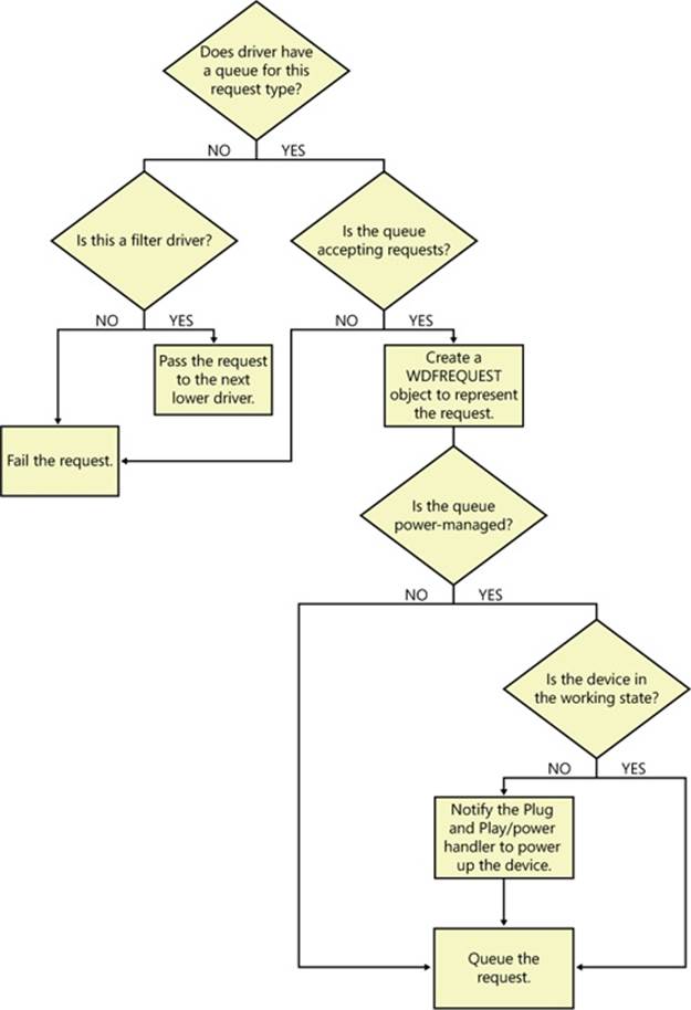
Figure 8-32. Handling read, write, and IOCTL I/O requests by KMDF
User-Mode Driver Framework (UMDF)
Although this chapter focuses on kernel-mode drivers, Windows includes a growing number of drivers that actually run in user mode, as previously described, using the User-Mode Driver Framework (UMDF) that is part of the WDF. Before finishing our discussion on drivers, we’ll take a quick look at the architecture of UMDF and what it offers. Once again, for a much more complete overview on the subject, please refer to http://msdn.microsoft.com/en-us/library/windows/hardware/gg463370.aspx.
UMDF is designed specifically to support what are called protocol device classes, which refers to devices that all use the same standardized, generic protocol and offer specialized functionality on top of it. These protocols currently include IEEE 1394 (FireWire), USB, Bluetooth, andTCP/IP. Any device running on top of these buses (or connected to a network) is a potential candidate for UMDF—examples include portable music players, PDAs, cell phones, cameras and webcams, and so on. Two other large users of UMDF are SideShow-compatible devices (auxiliary displays) and the Windows Portable Device (WPD) Framework, which supports USB removable storage (USB bulk transfer devices). Finally, as with KMDF, it’s possible to implement software-only drivers, such as for a virtual device, in UMDF.
To make porting code easier from kernel mode to user mode, and to keep a consistent architecture, UMDF uses the same conceptual driver programming model as KMDF, but it uses different components, interfaces, and data structures. For example, KMDF includes objects unique to kernel mode, while UMDF includes some objects unique to user mode. Objects and functionality that can’t be accessed through UMDF include direct handling of interrupts, DMA, nonpaged pool, and strict timing requirements. Furthermore, a UMDF driver can’t be on any kernel driver stack or be a client of another driver or the kernel itself.
Unlike KMDF drivers, which run as driver objects representing a .sys image file, UMDF drivers run in a driver host process, similar to a service-hosting process. The host process contains the driver itself (which is implemented as an in-process COM component), the user-mode driver framework (implemented as a DLL containing COM-like components for each UMDF object), and a run-time environment (responsible for I/O dispatching, driver loading, device-stack management, communication with the kernel, and a thread pool).
Just like in the kernel, each UMDF driver runs as part of a stack, which can contain multiple drivers that are responsible for managing a device. Naturally, since user-mode code can’t access the kernel address space, UMDF also includes some components that allow this access to occur through a specialized interface to the kernel. This is implemented by a kernel-mode side of UMDF that uses ALPC (see Chapter 3 in Part 1 for more information on advanced local procedure call) to talk to the run-time environment in the user-mode driver host processes.Figure 8-33 displays the architecture of the UMDF driver model.
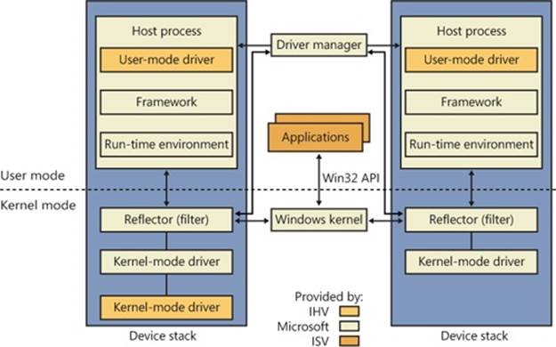
Figure 8-33. UMDF architecture
Figure 8-33 shows two different device stacks that manage two different hardware devices, each with a UMDF driver running inside its own driver host process. From the diagram, you can see that the following components take part in the architecture:
§ Applications Applications are the clients of the drivers. These are standard Windows applications that use the same APIs to perform I/Os as they would with a KMDF-managed or a WDM-managed device. Applications don’t know that they’re talking to a UMDF-based device, and the calls are still sent to the kernel’s I/O manager.
§ Windows kernel (I/O manager) Based on the application I/O APIs, the I/O manager builds the IRPs for the operations, just like for any other standard device.
§ Reflector The reflector is what makes UMDF “tick.” It is a standard WDM filter driver that sits at the top of the device stack of each device that is being managed by a UMDF driver. The reflector is responsible for managing the communication between the kernel and the user-mode driver host process. IRPs related to power management, Plug and Play, and standard I/O are redirected to the host process through ALPC. This lets the UMDF driver respond to the I/Os and perform work, as well as be involved in the Plug and Play model, by providing enumeration, installation, and management of its devices. The reflector is also responsible for keeping an eye on the driver host processes by making sure that they remain responsive to requests within an adequate time to prevent drivers and applications from hanging.
§ Driver manager The driver manager is responsible for starting and quitting the driver host processes, based on which UMDF-managed devices are present, and also for managing information on them. It is also responsible for responding to messages coming from the reflector and applying them to the appropriate host process (such as reacting to device installation). The driver manager runs as a standard Windows service and is configured for automatic startup as soon as the first UMDF driver for a device is installed. Only one instance of the driver manager runs for all driver host processes, and it must always be running to allow UMDF drivers to work.
§ Host process The host process provides the address space and run-time environment for the actual driver. Although it runs in the local service account, it is not actually a Windows service and is not managed by the SCM—only by the driver manager. The host process is also responsible for providing the user-mode device stack for the actual hardware, which is visible to all applications on the system. In the current UMDF release, each device instance has its own device stack, which runs in a separate host process. In the future, multiple instances may share the same host process. Host processes are child processes of the driver manager.
§ Kernel-mode drivers If specific kernel support for a device that is managed by a UMDF driver is needed, it is also possible to write a companion kernel-mode driver that fills that role. In this way, it is possible for a device to be managed both by a UMDF and a KMDF (or WDM) driver.
You can easily see UMDF in action on your system by inserting a USB flash drive with some content on it. Run Process Explorer, and you should see a WUDFHost.exe process that corresponds to a driver host process. Switch to DLL view and scroll down until you see DLLs similar to the ones shown in Figure 8-34.
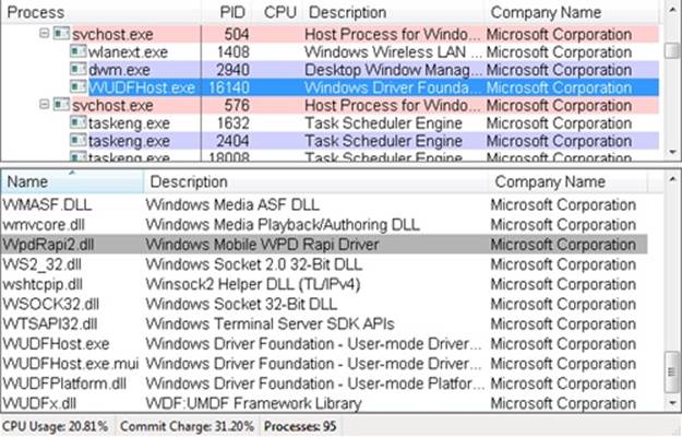
Figure 8-34. DLL in UMDF host process
You can identify three main components, which match the architectural overview described earlier:
§ WUDFx.dll, the framework itself
§ WUDFPlatform.dll, the run-time environment
§ WpdRapi2.dll, the COM component representing the WPD driver, exposing contents of USB storage devices to Windows shell and media applications
The Plug and Play (PnP) Manager
The PnP manager is the primary component involved in supporting the ability of Windows to recognize and adapt to changing hardware configurations. A user doesn’t need to understand the intricacies of hardware or manual configuration to install and remove devices. For example, it’s the PnP manager that enables a running Windows laptop that is placed on a docking station to automatically detect additional devices located in the docking station and make them available to the user.
Plug and Play support requires cooperation at the hardware, device driver, and operating system levels. Industry standards for the enumeration and identification of devices attached to buses are the foundation of Windows Plug and Play support. For example, the USB standard defines the way that devices on a USB bus identify themselves. With this foundation in place, Windows Plug and Play support provides the following capabilities:
§ The PnP manager automatically recognizes installed devices, a process that includes enumerating devices attached to the system during a boot and detecting the addition and removal of devices as the system executes.
§ Hardware resource allocation is a role the PnP manager fills by gathering the hardware resource requirements (interrupts, I/O memory, I/O registers, or bus-specific resources) of the devices attached to a system and, in a process called resource arbitration, optimally assigning resources so that each device meets the requirements necessary for its operation. Because hardware devices can be added to the system after boot-time resource assignment, the PnP manager must also be able to reassign resources to accommodate the needs of dynamically added devices.
§ Loading appropriate drivers is another responsibility of the PnP manager. The PnP manager determines, based on the identification of a device, whether a driver capable of managing the device is installed on the system, and if one is, it instructs the I/O manager to load it. If a suitable driver isn’t installed, the kernel-mode PnP manager communicates with the user-mode PnP manager to install the device, possibly requesting the user’s assistance in locating a suitable set of drivers.
§ The PnP manager also implements application and driver mechanisms for the detection of hardware configuration changes. Applications or drivers sometimes require a specific hardware device to function, so Windows includes a means for them to request notification of the presence, addition, or removal of devices.
§ It also provides a place for storage device state, and it participates in system setup, upgrade, migration, and offline image management.
§ In addition, it supports network connected devices, such as network projectors and printers, by allowing specialized bus drivers to detect the network as a bus and create device nodes for the devices running on it.
Level of Plug and Play Support
Windows aims to provide full support for Plug and Play, but the level of support possible depends on the attached devices and installed drivers. If a single device or driver doesn’t support Plug and Play, the extent of Plug and Play support for the system can be compromised. In addition, a driver that doesn’t support Plug and Play might prevent other devices from being usable by the system. Table 8-7 shows the outcome of various combinations of devices and drivers that can and can’t support Plug and Play.
Table 8-7. Device and Driver Plug and Play Capability
|
Type of Driver |
||
|
Type of Device |
Plug and Play |
Non–Plug and Play |
|
Plug and Play |
Full Plug and Play |
No Plug and Play |
|
Non–Plug and Play |
Possible partial Plug and Play |
No Plug and Play |
A device that isn’t Plug and Play–compatible is one that doesn’t support automatic detection, such as a legacy ISA sound card. Because the operating system doesn’t know where the hardware physically lies, certain operations—such as laptop undocking, sleep, and hibernation—are disallowed. However, if a Plug and Play driver is manually installed for the device, the driver can at least implement PnP manager–directed resource assignment for the device.
Drivers that aren’t Plug and Play–compatible include legacy drivers, such as those that ran on Windows NT 4. Although these drivers might continue to function on later versions of Windows, the PnP manager can’t reconfigure the resources assigned to such devices in the event that resource reallocation is necessary to accommodate the needs of a dynamically added device. For example, a device might be able to use I/O memory ranges A and B, and during the boot the PnP manager assigns it range A. If a device that can use only A is attached to the system later, the PnP manager can’t direct the first device’s driver to reconfigure itself to use range B. This prevents the second device from obtaining required resources, which results in the device being unavailable for use by the system. Legacy drivers also impair a machine’s ability to sleep or hibernate. (See the section The Power Manager later in this chapter for more details.)
Driver Support for Plug and Play
To support Plug and Play, a driver must implement a Plug and Play dispatch routine, a power management dispatch routine (described in the section The Power Manager later in this chapter), and an add-device routine. Bus drivers must support different types of Plug and Play requests than function or filter drivers do, however. For example, when the PnP manager is guiding device enumeration during the system boot (described in detail later in this chapter), it asks bus drivers for a description of the devices that they find on their respective buses. The description includes data that uniquely identifies each device as well as the resource requirements of the devices. The PnP manager takes this information and loads any function or filter drivers that have been installed for the detected devices. It then calls the add-device routine of each driver for every installed device the drivers are responsible for.
Function and filter drivers prepare to begin managing their devices in their add-device routines, but they don’t actually communicate with the device hardware. Instead, they wait for the PnP manager to send a start-device command for the device to their Plug and Play dispatch routine. Prior to sending the start-device command the PnP manager performs resource arbitration to decide what resources to assign the device. The start-device command includes the resource assignment that the PnP manager determines during resource arbitration. When a driver receives a start-device command, it can configure its device to use the specified resources. If an application tries to open a device that hasn’t finished starting, it receives an error indicating that the device does not exist.
After a device has started, the PnP manager can send the driver additional Plug and Play commands, including ones related to a device’s removal from the system or to resource reassignment. For example, when the user invokes the remove/eject device utility, shown in Figure 8-35(accessible by right-clicking on the USB connector icon in the taskbar and selecting Eject USB Mass Storage Device), to tell Windows to eject a USB flash drive, the PnP manager sends a query-remove notification to any applications that have registered for Plug and Play notifications for the device. Applications typically register for notification on their handles, which they close during a query-remove notification. If no applications veto the query-remove request, the PnP manager sends a query-remove command to the driver that owns the device being ejected. At that point, the driver has a chance to deny the removal or to ensure that any pending I/O operations involving the device have completed and to begin rejecting further I/O requests aimed at the device. If the driver agrees to the remove request and no open handles to the device remain, the PnP manager next sends a remove command to the driver to request that the driver discontinue accessing the device and release any resources the driver has allocated on behalf of the device.
Figure 8-35. Remove/eject utility
When the PnP manager needs to reassign a device’s resources, it first asks the driver whether it can temporarily suspend further activity on the device by sending the driver a query-stop command. The driver either agrees to the request, if doing so wouldn’t cause data loss or corruption, or denies the request. As with a query-remove command, if the driver agrees to the request, the driver completes pending I/O operations and won’t initiate further I/O requests for the device that can’t be aborted and subsequently restarted. The driver typically queues new I/O requests so that the resource reshuffling is transparent to applications currently accessing the device. The PnP manager then sends the driver a stop command. At that point, the PnP manager can direct the driver to assign different resources to the device and once again send the driver a start-device command for the device.
The various Plug and Play commands essentially guide a device through an assortment of operational states, forming a well-defined state-transition table, which is shown in simplified form in Figure 8-36. (Several possible transitions and Plug and Play commands have been omitted for clarity. Also, the state diagram depicted is that implemented by function drivers. Bus drivers implement a more complex state diagram.) A state shown in the figure that we haven’t discussed is the one that results from the PnP manager’s surprise-remove command. This command results when either a user removes a device without warning, as when the user ejects a PCMCIA card without using the remove/eject utility, or the device fails. The surprise-remove command tells the driver to immediately cease all interaction with the device because the device is no longer attached to the system and to cancel any pending I/O requests.
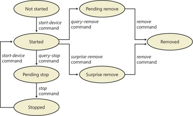
Figure 8-36. Device Plug and Play state transitions
Driver Loading, Initialization, and Installation
Driver loading and initialization on Windows consists of two types of loading: explicit loading and enumeration-based loading. Explicit loading is guided by the HKLM\SYSTEM\CurrentControlSet\Services branch of the registry, as described in the section “Service Applications” in Chapter 4 in Part 1. Enumeration-based loading results when the PnP manager dynamically loads drivers for the devices that a bus driver reports during bus enumeration.
The Start Value
In Chapter 4 in Part 1, we explained that every driver and Windows service has a registry key under the Services branch of the current control set. The key includes values that specify the type of the image (for example, Windows service, driver, and file system), the path to the driver or service’s image file, and values that control the driver or service’s load ordering. There are two main differences between explicit device driver loading and Windows service loading:
§ Only device drivers can specify Start values of boot-start (0) or system-start (1).
§ Device drivers can use the Group and Tag values to control the order of loading within a phase of the boot, but unlike services, they can’t specify DependOnGroup or DependOnService values.
Chapter 13, describes the phases of the boot process and explains that a driver Start value of 0 means that the operating system loader loads the driver. A Start value of 1 means that the I/O manager loads the driver after the executive subsystems have finished initializing. The I/O manager calls driver initialization routines in the order that the drivers load within a boot phase. Like Windows services, drivers use the Group value in their registry key to specify which group they belong to; the registry value HKLM\SYSTEM\CurrentControlSet\Control\ServiceGroupOrder\List determines the order that groups are loaded within a boot phase.
A driver can further refine its load order by including a Tag value to control its order within a group. The I/O manager sorts the drivers within each group according to the Tag values defined in the drivers’ registry keys. Drivers without a tag go to the end of the list in their group. You might assume that the I/O manager initializes drivers with lower-number tags before it initializes drivers with higher-number tags, but such isn’t necessarily the case. The registry key HKLM\SYSTEM\CurrentControlSet\Control\GroupOrderList defines tag precedence within a group; with this key, Microsoft and device driver developers can take liberties with redefining the integer number system.
Here are the guidelines by which drivers set their Start value:
§ Non–Plug and Play drivers set their Start value to reflect the boot phase they want to load in.
§ Drivers, including both Plug and Play and non–Plug and Play drivers, that must be loaded by the boot loader during the system boot specify a Start value of boot-start (0). Examples include system bus drivers and the boot file system driver.
§ A driver that isn’t required for booting the system and that detects a device that a system bus driver can’t enumerate specifies a Start value of system-start (1). An example is the serial port driver, which informs the PnP manager of the presence of standard PC serial ports that were detected by Setup and recorded in the registry.
§ A non–Plug and Play driver or file system driver that doesn’t have to be present when the system boots specifies a Start value of auto-start (2). An example is the Multiple Universal Naming Convention (UNC) Provider (MUP) driver, which provides support for UNC-based path names to remote resources (for example, \\REMOTECOMPUTERNAME\SHARE).
§ Plug and Play drivers that aren’t required to boot the system specify a Start value of demand-start (3). Examples include network adapter drivers.
The only purpose that the Start values for Plug and Play drivers and drivers for enumerable devices have is to ensure that the operating system loader loads the driver—if the driver is required for the system to boot successfully. Beyond that, the PnP manager’s device enumeration process, described next, determines the load order for Plug and Play drivers.
Device Enumeration
The PnP manager begins device enumeration with a virtual bus driver called Root, which represents the entire computer system and acts as the bus driver for non–Plug and Play drivers and for the HAL. The HAL acts as a bus driver that enumerates devices directly attached to themotherboard as well as system components such as batteries. Instead of actually enumerating, the HAL relies on the hardware description the Setup process recorded in the registry to detect the primary bus (a PCI bus in most cases) and devices such as batteries and fans.
The primary bus driver enumerates the devices on its bus, possibly finding other buses, for which the PnP manager initializes drivers. Those drivers in turn can detect other devices, including other subsidiary buses. This recursive process of enumeration, driver loading (if the driver isn’t already loaded), and further enumeration proceeds until all the devices on the system have been detected and configured.
As the bus drivers report detected devices to the PnP manager, the PnP manager creates an internal tree called the device tree that represents the relationships between devices. Nodes in the tree are called devnodes, and a devnode contains information about the device objects that represent the device as well as other Plug and Play–related information stored in the devnode by the PnP manager. Figure 8-37 shows an example of a simplified device tree. This system is ACPI-compliant, so an ACPI-compliant HAL serves as the primary bus enumerator. A PCI bus serves as the system’s primary bus, which USB, ISA, and SCSI buses are connected to.
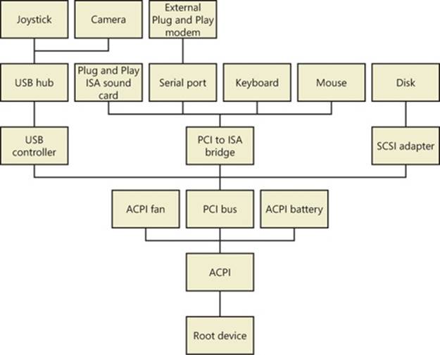
Figure 8-37. Example device tree
The Device Manager utility, which is accessible from the Computer Management snap-in in the Programs/Administrative Tools folder of the Start menu (and also from the Device Manager link of the System utility in Control Panel), shows a simple list of devices present on a system in its default configuration. You can also select the Devices By Connection option from the Device Manager’s View menu to see the devices as they relate to the device tree. Figure 8-38 shows an example of the Device Manager’s Devices By Connection view.
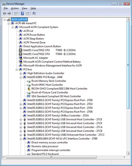
Figure 8-38. Device Manager showing the device tree
Taking device enumeration into account, the load and initialization order of drivers is as follows:
1. The I/O manager invokes the driver entry routine of each boot-start driver. If a boot driver has child devices, the I/O manager enumerates those devices, reporting their presence to the PnP manager. The child devices are configured and started if their drivers are boot-start drivers. If a device has a driver that isn’t a boot-start driver, the PnP manager creates a devnode for the device but doesn’t start it or load its driver.
2. After the boot-start drivers are initialized, the PnP manager walks the device tree, loading the drivers for devnodes that weren’t loaded in step 1 and starting their devices. As each device starts, the PnP manager enumerates related child devices, if a device has any, starting those devices’ drivers and performing enumeration of their children as required. The PnP manager loads the drivers for detected devices in this step regardless of the driver’s Start value. (The one exception is if the Start value is set to disabled.) At the end of this step, all Plug and Play devices have their drivers loaded and are started, except devices that aren’t enumerable and the children of those devices.
3. The PnP manager loads any drivers with a Start value of system-start that aren’t yet loaded. Those drivers detect and report their nonenumerable devices. The PnP manager loads drivers for those devices until all enumerated devices are configured and started.
4. The service control manager loads drivers marked as auto-start.
The device tree serves to guide both the PnP manager and the power manager as they issue Plug and Play and power IRPs to devices. In general, IRPs flow from the top of a devnode to the bottom, and in some cases a driver in one devnode creates new IRPs to send to other devnodes, always moving toward the root. The flow of Plug and Play and power IRPs is further described later in this chapter.
EXPERIMENT: DUMPING THE DEVICE TREE
A more detailed way to view the device tree than using Device Manager is to use the !devnode kernel debugger command. Specifying 0 1 as command options dumps the internal device tree devnode structures, indenting entries to show their hierarchical relationships, as shown here:
lkd> !devnode 0 1
Dumping IopRootDeviceNode (= 0x85161a98)
DevNode 0x85161a98 for PDO 0x84d10390
InstancePath is "HTREE\ROOT\0"
State = DeviceNodeStarted (0x308)
Previous State = DeviceNodeEnumerateCompletion (0x30d)
DevNode 0x8515bea8 for PDO 0x8515b030
DevNode 0x8515c698 for PDO 0x8515c820
InstancePath is "Root\ACPI_HAL\0000"
State = DeviceNodeStarted (0x308)
Previous State = DeviceNodeEnumerateCompletion (0x30d)
DevNode 0x84d1c5b0 for PDO 0x84d1c738
InstancePath is "ACPI_HAL\PNP0C08\0"
ServiceName is "ACPI"
State = DeviceNodeStarted (0x308)
Previous State = DeviceNodeEnumerateCompletion (0x30d)
DevNode 0x85ebf1b0 for PDO 0x85ec0210
InstancePath is "ACPI\GenuineIntel_-_x86_Family_6_Model_15\_0"
ServiceName is "intelppm"
State = DeviceNodeStarted (0x308)
Previous State = DeviceNodeEnumerateCompletion (0x30d)
DevNode 0x85ed6970 for PDO 0x8515e618
InstancePath is "ACPI\GenuineIntel_-_x86_Family_6_Model_15\_1"
ServiceName is "intelppm"
State = DeviceNodeStarted (0x308)
Previous State = DeviceNodeEnumerateCompletion (0x30d)
DevNode 0x85ed75c8 for PDO 0x85ed79e8
InstancePath is "ACPI\ThermalZone\THM_"
State = DeviceNodeStarted (0x308)
Previous State = DeviceNodeEnumerateCompletion (0x30d)
DevNode 0x85ed6cd8 for PDO 0x85ed6858
InstancePath is "ACPI\pnp0c14\0"
ServiceName is "WmiAcpi"
State = DeviceNodeStarted (0x308)
Previous State = DeviceNodeEnumerateCompletion (0x30d)
DevNode 0x85ed7008 for PDO 0x85ed6730
InstancePath is "ACPI\ACPI0003\2&daba3ff&2"
ServiceName is "CmBatt"
State = DeviceNodeStarted (0x308)
Previous State = DeviceNodeEnumerateCompletion (0x30d)
DevNode 0x85ed7e60 for PDO 0x84d2e030
InstancePath is "ACPI\PNP0C0A\1"
ServiceName is "CmBatt"
...
Information shown for each devnode includes the InstancePath, which is the name of the device’s enumeration registry key stored under HKLM\SYSTEM\CurrentControlSet\Enum, and the ServiceName, which corresponds to the device’s driver registry key under HKLM\SYSTEM\CurrentControlSet\Services. To see the resources, such as interrupts, ports, and memory, assigned to each devnode, specify 0 3 as the command options for the !devnode command.
A record of all the devices detected since the system was installed is recorded under the HKLM\SYSTEM\CurrentControlSet\Enum registry key. Subkeys are in the form <Enumerator>\<Device ID>\<Instance ID>, where the enumerator is a bus driver, the device ID is a unique identifier for a type of device, and the instance ID uniquely identifies different instances of the same hardware.
Device Stacks
As the devnodes are created by the PnP manager, driver objects and device objects are created to manage and logically represent the linkage between the devnodes. This linkage is called a device stack, and it can be thought of as an ordered list of device object/driver pairs. Each device stack has a bottom and top, and Figure 8-39 shows that a device stack is made up of at least two, and sometimes more, device objects:
§ A physical device object (PDO) that the PnP manager instructs a bus driver to create when the bus driver reports the presence of a device on its bus during enumeration. The PDO represents the physical interface to the device and is always on the bottom of the device stack.
§ One or more optional filter device objects (FiDOs) that layer between the PDO and the functional device object (FDO; described later in this list) and that are created by bus filter drivers.
§ One or more optional FiDOs that layer between the PDO and the FDO (and that layer above any FiDOs created by bus filter drivers) that are created by lower-level filter drivers.
§ One (and only one) functional device object (FDO) that is created by the driver, which is called a function driver, that the PnP manager loads to manage a detected device. An FDO represents the logical interface to a device. A function driver can also act as a bus driver if devices are attached to the device represented by the FDO. The function driver often creates an interface (described earlier) to the FDO’s corresponding PDO so that applications and other drivers can open the device and interact with it. Sometimes function drivers are divided into a separate class/port driver and miniport driver that work together to manage I/O for the FDO.
§ One or more optional FiDOs that layer above the FDO and that are created by upper-level filter drivers.
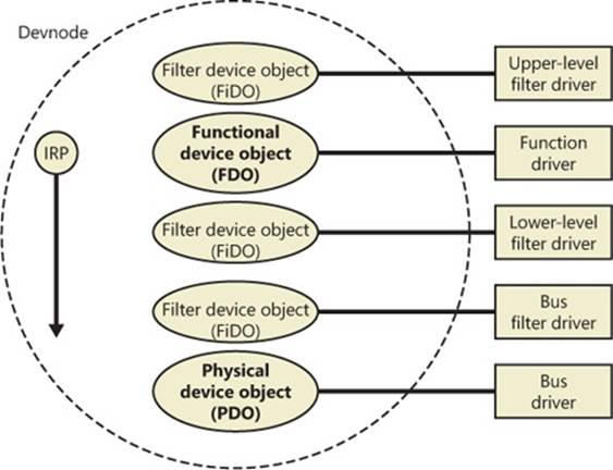
Figure 8-39. Device stack internals
Device stacks are built from the bottom up and rely on the I/O manager’s layering functionality, so IRPs flow from the top of a device stack toward the bottom. However, any level in the device stack can choose to complete an IRP. For example, the function driver can handle a read request without passing the IRP to the bus driver. Only when the function driver requires the help of a bus driver to perform bus-specific processing does the IRP flow all the way to the bottom and then into the device stack containing the bus driver.
Device Stack Driver Loading
So far, we’ve avoided answering two important questions: “How does the PnP manager determine what function driver to load for a particular device?” and “How do filter drivers register their presence so that they are loaded at appropriate times in the creation of a device stack?”
The answer to both these questions lies in the registry. When a bus driver performs device enumeration, it reports device identifiers for the devices it detects back to the PnP manager. The identifiers are bus-specific; for a USB bus, an identifier consists of a vendor ID (VID) for the hardware vendor that made the device and a product ID (PID) that the vendor assigned to the device. (See the WDK for more information on device ID formats.) Together these IDs form what Plug and Play calls a device ID. The PnP manager also queries the bus driver for an instance ID to help it distinguish different instances of the same hardware. The instance ID can describe either a bus-relative location (for example, the USB port) or a globally unique descriptor (for example, a serial number).
The device ID and instance ID are combined to form a device instance ID (DIID), which the PnP manager uses to locate the device’s key in the enumeration branch of the registry (HKLM\SYSTEM\CurrentControlSet\Enum). Figure 8-40 presents an example of a keyboard’s enumeration subkey. The device’s key contains descriptive data and includes values named Service and ClassGUID (which are obtained from a driver’s INF file) that help the PnP manager locate the device’s drivers.
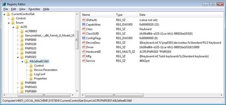
Figure 8-40. Keyboard enumeration key
To deal with multifunction devices (such as all-in-one printers or cell phones with integrated camera and music player functionalities), Windows also supports a container ID property that can be associated with a devnode. The container ID is a globally unique identifier (GUID) that is unique to a single instance of a physical device and shared between all the function devnodes that belong to it, as shown in Figure 8-41.
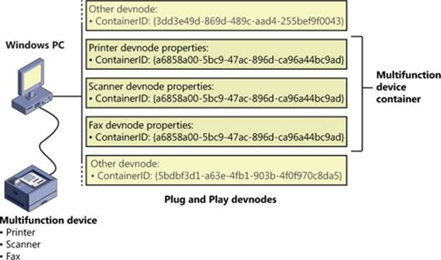
Figure 8-41. All-in-one printer with a unique ID as seen by the PnP manager
The container ID is a property that, similar to the instance ID, is reported back by the bus driver of the corresponding hardware. Then, when the device is being enumerated, all devnodes associated with the same PDO share the container ID. Because Windows already supports many buses out of the box—such as PnP-X, Bluetooth, and USB—most device drivers can simply return the bus-specific ID, from which Windows will generate the corresponding container ID. For other kinds of devices or buses, the driver can generate its own unique ID through software.
Finally, when device drivers do not supply a container ID, Windows can make educated guesses by querying the topology for the bus, when that’s available, through mechanisms such as ACPI. By understanding whether a certain device is a child of another, and whether it is removable, hot-pluggable, or user-reachable (as opposed to an internal motherboard component), Windows is able to assign container IDs to device nodes that reflect multifunction devices correctly.
The final end-user benefit of grouping devices by container IDs is visible in the Devices And Printers UI present in modern versions of Windows. This feature is able to display the scanner, printer, and faxing components of an all-in-one printer as a single graphical element instead of as three distinct devices. For example, in Figure 8-42, the HP PSC 1500 series is identified as a single device.
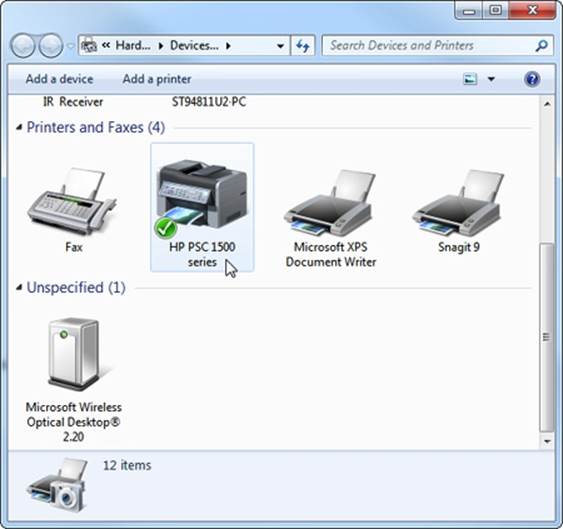
Figure 8-42. Devices And Printers
EXPERIMENT: VIEWING DETAILED DEVNODE INFORMATION IN DEVICE MANAGER
The Device Manager applet that you can access from the Hardware link of the System Control Panel application shows detailed information about a device node on its Details tab. The tab allows you to view an assortment of fields, including the devnode’s device instance ID, hardware ID, service name, filters, and power capabilities.
The following screen shows the selection combo box of the Details tab expanded to reveal the types of information you can access:
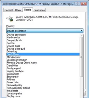
Using the ClassGUID value, the PnP manager locates the device’s class key under HKLM\SYSTEM\CurrentControlSet\Control\Class. The keyboard class key is shown in Figure 8-43. The enumeration key and class key supply the PnP manager with the information it needs to load the drivers necessary for the device’s devnode. Drivers are loaded in the following order:
1. Any lower-level filter drivers specified in the LowerFilters value of the device’s enumeration key.
2. Any lower-level filter drivers specified in the LowerFilters value of the device’s class key.
3. The function driver specified by the Service value in the device’s enumeration key. This value is interpreted as the driver’s key under HKLM\SYSTEM\CurrentControlSet\Services.
4. Any upper-level filter drivers specified in the UpperFilters value of the device’s enumeration key.
5. Any upper-level filter drivers specified in the UpperFilters value of the device’s class key.
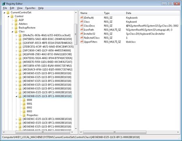
Figure 8-43. Keyboard class key
In all cases, drivers are referenced by the name of their key under HKLM\SYSTEM\CurrentControlSet\Services.
NOTE
The WDK refers to a device’s enumeration key as its hardware key and to the class key as the software key.
The keyboard device shown in Figure 8-40 and Figure 8-43 has no lower-level filter drivers. The function driver is the i8042prt driver, and there are two upper-level filter drivers specified in the keyboard’s class key: kbdclass and vmkbd2.
Driver Installation
If the PnP manager encounters a device for which no driver is installed, it relies on the user-mode PnP manager to guide the installation process. If the device is detected during the system boot, a devnode is defined for the device, but the loading process is postponed until the user-mode PnP manager starts. (The user-mode PnP manager is implemented in %SystemRoot%\System32\Umpnpmgr.dll and runs in a service hosting process (Svchost.exe).)
The components involved in a driver’s installation are shown in Figure 8-44. Dark-shaded objects in the figure correspond to components generally supplied by the system, whereas lighter-shaded objects are those included in a driver’s installation files. First, a bus driver informs thePnP manager of a device it enumerates using a DIID (1). The PnP manager checks the registry for the presence of a corresponding function driver, and when it doesn’t find one, it informs the user-mode PnP manager (2) of the new device by its DIID. The user-mode PnP manager first tries to perform an automatic install without user intervention. If the installation process involves the posting of dialog boxes that require user interaction and the currently logged-on user has administrator privileges, (3) the user-mode PnP manager launches the Rundll32.exe application (the same application that hosts Control Panel utilities) to execute the Hardware Installation Wizard (%SystemRoot%\System32\Newdev.dll). If the currently logged-on user doesn’t have administrator privileges (or if no user is logged on) and the installation of the device requires user interaction, the user-mode PnP manager defers the installation until a privileged user logs on. The Hardware Installation Wizard uses Setupapi.dll and CfgMgr32.dll (configuration manager) API functions to locate INF files that correspond to drivers that are compatible with the detected device. This process might involve having the user insert installation media containing a vendor’s INF files, or the wizard might locate a suitable INF file in the driver store (%SystemRoot%\System32\DriverStore) that contains drivers that ship with Windows or others that are downloaded through Windows Update. Installation is performed in two steps. In the first, the third-party driver developer imports the driver package into the driver store, and in the second step, the system performs the actual installation, which is always done through the %SystemRoot%\System32\Drvinst.exe process.
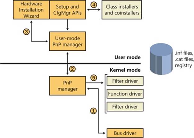
Figure 8-44. Driver installation components
To find drivers for the new device, the installation process gets a list of hardware IDs and compatible IDs from the bus driver. These IDs describe all the various ways the hardware might be identified in a driver installation file (.inf). The lists are ordered so that the most specific description of the hardware is listed first. If matches are found in multiple INFs, more precise matches are preferred over less precise matches, digitally signed INFs are preferred over unsigned ones, and newer signed INFs are preferred over older signed ones. If a match is found based on a compatible ID, the Hardware Installation Wizard can choose to prompt for media in case a more up-to-date driver came with the hardware.
The INF file locates the function driver’s files and contains commands that fill in the driver’s enumeration and class keys, and the INF file might direct the Hardware Installation Wizard to (4) launch class or device coinstaller DLLs that perform class-specific or device-specific installation steps, such as displaying configuration dialog boxes that let the user specify settings for a device.
EXPERIMENT: LOOKING AT A DRIVER’S INF FILE
When a driver or other software that has an INF file is installed, the system copies its INF file to the %SystemRoot%\Inf directory. One file that will always be there is Keyboard.inf because it’s the INF file for the keyboard class driver. View its contents by opening it in Notepad and you should see something like this:
; Copyright (c) Microsoft Corporation. All rights reserved.
[Version]
Signature="$Windows NT$"
Class=Keyboard
ClassGUID={4D36E96B-E325-11CE-BFC1-08002BE10318}
Provider=%MS%
DriverVer=06/21/2006,6.1.7601.17514
[SourceDisksNames]
3426=windows cd
...
If you search the file for “.sys”, you’ll come across the entry that directs the user-mode PnP manager to install the i8042prt.sys and kbdclass.sys drivers:
...
[STANDARD_CopyFiles]
i8042prt.sys,,,0x100
kbdclass.sys,,,0x100
...
Before actually installing a driver, the user-mode PnP manager checks the system’s driver-signing policy. If the settings specify that the system should block or warn of the installation of unsigned drivers, the user-mode PnP manager checks the driver’s INF file for an entry that locates a catalog (a file that ends with the .cat extension) containing the driver’s digital signature.
Microsoft’s WHQL tests the drivers included with Windows and those submitted by hardware vendors. When a driver passes the WHQL tests, it is “signed” by Microsoft. This means that WHQL obtains a hash, or unique value representing the driver’s files, including its image file, and then cryptographically signs it with Microsoft’s private driver-signing key. The signed hash is stored in a catalog file and included on the Windows installation media or returned to the vendor that submitted the driver for inclusion with its driver.
EXPERIMENT: VIEWING CATALOG FILES
When you install a component such as a driver that includes a catalog file, Windows copies the catalog file to a directory under %SystemRoot%\System32\Catroot. Navigate to that directory in Explorer and you find the subdirectory that contains .cat files. Nt5.cat and Nt5ph.cat store the signatures and page hashes for Windows system files, for example.
If you open one of the catalog files, a dialog box appears with two pages. The page labeled General shows information about the signature on the catalog file, and the Security Catalog page has the hashes of the components that are signed with the catalog file. This screen shot of a catalog file for NVIDIA video drivers shows the hash for the video adapter’s kernel miniport driver. Other hashes in the catalog are associated with the various support DLLs that ship with the driver.
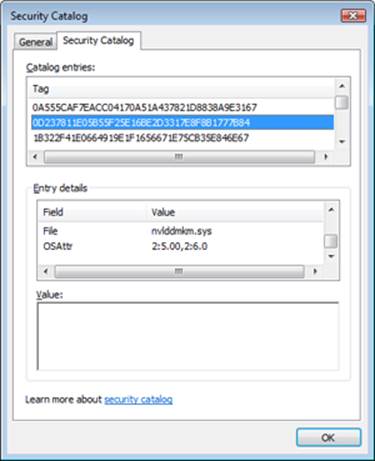
As it is installing a driver, the user-mode PnP manager extracts the driver’s signature from its catalog file, decrypts the signature using the public half of Microsoft’s driver-signing private/public key pair, and compares the resulting hash with a hash of the driver file it’s about to install. If the hashes match, the driver is verified as having passed WHQL testing. If a driver fails the signature verification, the user-mode PnP manager acts according to the settings of the system driver-signing policy, either failing the installation attempt, warning the user that the driver isunsigned, or silently installing the driver.
NOTE
Drivers installed using setup programs that manually configure the registry and copy driver files to a system and driver files that are dynamically loaded by applications aren’t checked for signatures by the PnP manager’s signing policy. Instead, they are checked by the Kernel Mode Code Signing policy described in Chapter 3 in Part 1. Only drivers installed using INF files are validated against the PnP manager’s driver-signing policy.
After a driver is installed, the kernel-mode PnP manager (step 5 in Figure 8-44) starts the driver and calls its add-device routine to inform the driver of the presence of the device it was loaded for. The construction of the device stack then continues as described earlier.
NOTE
The user-mode PnP manager also checks to see whether the driver it’s about to install is on the protected driver list maintained by Windows Update and, if so, blocks the installation with a warning to the user. Drivers that are known to have incompatibilities or bugs are added to the list and blocked from installation.
The Power Manager
Just as Windows Plug and Play features require support from a system’s hardware, its power-management capabilities require hardware that complies with the Advanced Configuration and Power Interface (ACPI) specification (available at http://www.acpi.info).
The ACPI standard defines various power levels for a system and for devices. The six system power states are described in Table 8-8. They are referred to as S0 (fully on or working) through S5 (fully off). Each state has the following characteristics:
§ Power consumption The amount of power the computer consumes
§ Software resumption The software state from which the computer resumes when moving to a “more on” state
§ Hardware latency The length of time it takes to return the computer to the fully on state
States S1 through S4 are sleeping states, in which the computer appears to be off because of reduced power consumption. However, the computer retains enough information, either in memory or on disk, to move to S0. For states S1 through S3, enough power is required to preserve the contents of the computer’s memory so that when the transition is made to S0 (when the user or a device wakes up the computer), the power manager continues executing where it left off before the suspend.
Table 8-8. System Power-State Definitions
|
State |
Power Consumption |
Software Resumption |
Hardware Latency |
|
S0 (fully on) |
Maximum |
Not applicable |
None |
|
S1 (sleeping) |
Less than S0, more than S2 |
System resumes where it left off (returns to S0) |
Less than 2 seconds |
|
S2 (sleeping) |
Less than S1, more than S3 |
System resumes where it left off (returns to S0) |
2 or more seconds |
|
S3 (sleeping) |
Less than S2; processor is off |
System resumes where it left off (returns to S0) |
Same as S2 |
|
S4 (hibernating) |
Trickle current to power button and wake circuitry |
System restarts from saved hibernatation file and resumes where it left off prior to hibernation (returns to S0) |
Long and undefined |
|
S5 (fully off) |
Trickle current to power button |
System boot |
Long and undefined |
When the system moves to S4, the power manager saves the compressed contents of memory to a hibernation file named Hiberfil.sys, which is large enough to hold the uncompressed contents of memory, in the root directory of the system volume. (Compression is used to minimize disk I/O and to improve hibernation and resume-from-hibernation performance.) After it finishes saving memory, the power manager shuts off the computer. When a user subsequently turns on the computer, a normal boot process occurs, except that Bootmgr checks for and detects a valid memory image stored in the hibernation file. If the hibernation file contains saved system state, Bootmgr launches Winresume, which reads the contents of the file into memory, and then resumes execution at the point in memory that is recorded in the hibernation file.
On systems with hybrid sleep enabled (by default, only desktop computers), a user request to put the computer to sleep will actually be a combination of both the S3 state and the S4 state: while the computer is put to sleep, an emergency hibernation file will also be written to disk. Unlike typical hibernation files, which contain almost all active memory, the emergency hibernation file includes only data that could not be paged in at a later time, making the suspend operation faster than a typical hibernation (because less data is written to disk). Drivers will then be notified that an S4 transition is occurring, allowing them to configure themselves and save state just as if an actual hibernation request had been initiated. After this point, the system is put in the normal sleep state just like during a standard sleep transition. However, if the power goes out, the system is now essentially in an S4 state—the user can power on the machine, and Windows will resume from the emergency hibernation file.
The computer never directly transitions between states S1 and S4; instead, it must move to state S0 first. As illustrated in Figure 8-45, when the system is moving from any of states S1 through S5 to state S0, it’s said to be waking, and when it’s transitioning from state S0 to any of states S1 through S5, it’s said to be sleeping.
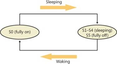
Figure 8-45. System power-state transitions
Although the system can be in one of six power states, ACPI defines devices as being in one of four power states, D0 through D3. State D0 is fully on, and state D3 is fully off. The ACPI standard leaves it to individual drivers and devices to define the meanings of states D1 and D2, except that state D1 must consume an amount of power less than or equal to that consumed in state D0, and when the device is in state D2, it must consume power less than or equal to that consumed in D1. Microsoft, in conjunction with the major hardware OEMs, has defined a series of power management reference specifications that specify the device power states that are required for all devices in a particular class (for the major device classes: display, network, SCSI, and so on). For some devices, there’s no intermediate power state between fully on and fully off, which results in these states being undefined.
Power Manager Operation
Power management policy in Windows is split between the power manager and the individual device drivers. The power manager is the owner of the system power policy. This ownership means that the power manager decides which system power state is appropriate at any given point, and when a sleep, hibernation, or shutdown is required, the power manager instructs the power-capable devices in the system to perform appropriate system power-state transitions. The power manager decides when a system power-state transition is necessary by considering a number of factors:
§ System activity level
§ System battery level
§ Shutdown, hibernate, or sleep requests from applications
§ User actions, such as pressing the power button
§ Control Panel power settings
When the PnP manager performs device enumeration, part of the information it receives about a device is its power-management capabilities. A driver reports whether or not its devices support device states D1 and D2 and, optionally, the latencies, or times required, to move from states D1 through D3 to D0. To help the power manager determine when to make system power-state transitions, bus drivers also return a table that implements a mapping between each of the system power states (S0 through S5) and the device power states that a device supports.
The table lists the lowest possible device power state for each system state and directly reflects the state of various power planes when the machine sleeps or hibernates. For example, a bus that supports all four device power states might return the mapping table shown in Table 8-9. Most device drivers turn their devices completely off (D3) when leaving S0 to minimize power consumption when the machine isn’t in use. Some devices, however, such as network adapter cards, support the ability to wake up the system from a sleeping state. This ability, along with the lowest device power state in which the capability is present, is also reported during device enumeration.
Table 8-9. Example System-to-Device Power Mappings
|
System Power State |
Device Power State |
|
S0 (fully on) |
D0 (fully on) |
|
S1 (sleeping) |
D1 |
|
S2 (sleeping) |
D2 |
|
S3 (sleeping) |
D2 |
|
S4 (hibernating) |
D3 (fully off) |
|
S5 (fully off) |
D3 (fully off) |
Driver Power Operation
When the power manager decides to make a transition between system power states, it sends power commands to a driver’s power dispatch routine. More than one driver can be responsible for managing a device, but only one of the drivers is designated as the device power-policy owner. This driver determines, based on the system state, a device’s power state. For example, if the system transitions between state S0 and S1, a driver might decide to move a device’s power state from D0 to D1.
Instead of directly informing the other drivers that share the management of the device of its decision, the device power-policy owner asks the power manager, via the PoRequestPowerIrp function, to tell the other drivers by issuing a device power command to their power dispatch routines. This behavior allows the power manager to control the number of power commands that are active on a system at any given time. For example, some devices in the system might require a significant amount of current to power up. The power manager ensures that such devices aren’t powered up simultaneously.
EXPERIMENT: VIEWING A DRIVER’S POWER MAPPINGS
You can see a driver’s system power state to driver power state mappings with Device Manager. Open the Properties dialog box for a device, and choose the Power Data entry in the drop-down list on the Details tab to see the mappings.
The dialog box also displays the current power state of the device, the device-specific power capabilities that it provides, and the power states from which it is able to wake the system.
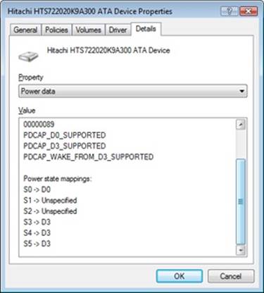
Many power commands have corresponding query commands. For example, when the system is moving to a sleep state, the power manager will first ask the devices on the system whether the transition is acceptable. A device that is busy performing time-critical operations or interacting with device hardware might reject the command, which results in the system maintaining its current system power-state setting.
EXPERIMENT: VIEWING THE SYSTEM POWER CAPABILITIES AND POLICY
You can view a computer’s system power capabilities by using the !pocaps kernel debugger command. Here’s the output of the command when run on an ACPI-compliant laptop:
lkd> !pocaps
PopCapabilities @ 0x82114d80
Misc Supported Features: PwrButton SlpButton Lid S3 S4 S5 HiberFile FullWake
VideoDim
Processor Features: Thermal
Disk Features: SpinDown
Battery Features: BatteriesPresent
Battery 0 - Capacity: 0 Granularity: 0
Battery 1 - Capacity: 0 Granularity: 0
Battery 2 - Capacity: 0 Granularity: 0
Wake Caps
Ac OnLine Wake: Sx
Soft Lid Wake: Sx
RTC Wake: S4
Min Device Wake: Sx
Default Wake: Sx
The Misc Supported Features line reports that, in addition to S0 (fully on), the system supports system power states S1, S3, S4, and S5 (it doesn’t implement S2) and has a valid hibernation file to which it can save system memory when it hibernates (state S4).
The Power Options page, shown here (available by selecting Power Options in Control Panel), lets you configure various aspects of the system’s power policy. The exact properties you can configure depend on the system’s power capabilities, which we just examined.
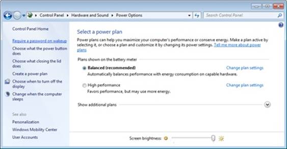
By changing any of the preconfigured plan settings, you can set the idle detection timeouts that control when the system turns off the monitor, spins down hard disks, goes to standby mode (moves to system power state S1), and hibernates (moves the system to power state S4). In addition, selecting the Change Plan Settings option lets you specify the power-related behavior of the system when you press the power or sleep buttons or close a laptop’s lid.
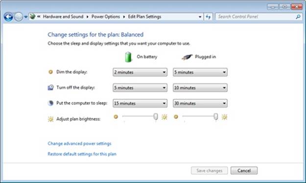
The settings you configure by clicking the Change Advanced Power Settings link directly affect values in the system’s power policy, which you can display with the !popolicy debugger command. Here’s the output of the command on the same system:
lkd> !popolicy
SYSTEM_POWER_POLICY (R.1) @ 0x82107994
PowerButton: Sleep Flags: 00000000 Event: 00000000
SleepButton: Sleep Flags: 00000000 Event: 00000000
LidClose: Sleep Flags: 00000000 Event: 00000000
Idle: Sleep Flags: 00000000 Event: 00000000
OverThrottled: None Flags: 00000000 Event: 00000000
IdleTimeout: 384 IdleSensitivity: 90%
MinSleep: S3 MaxSleep: S3
LidOpenWake: S0 FastSleep: S0
WinLogonFlags: 1 S4Timeout: fd20
VideoTimeout: 300 VideoDim: 0
SpinTimeout: 258 OptForPower: 0
FanTolerance: 0% ForcedThrottle: 0%
SpinTimeout: 258 OptForPower: 0
MinThrottle: 0% DyanmicThrottle: None
The first lines of the display correspond to the button behaviors specified on the Advanced Settings tab of Power Options, and on this system both the power and the sleep buttons put the computer in a sleep state, just as closing the lid does.
The timeout values shown at the end of the output are expressed in seconds and displayed in hexadecimal notation. The values reported here directly correspond to the settings you can see configured on the Power Options page. (The laptop is on battery.) For example, the video timeout is 300, meaning the monitor turns off after 300 seconds, or 5 minutes, and the hard disk spin-down timeout is 0x258, which corresponds to 600 seconds, or 10 minutes.
Driver and Application Control of Device Power
Besides responding to power manager commands related to system power-state transitions, a driver can unilaterally control the device power state of its devices. In some cases, a driver might want to reduce the power consumption of a device it controls when the device is left inactive for a period of time. Examples include monitors that support a dimmed mode and disks that support spin-down. A driver can either detect an idle device itself or use facilities provided by the power manager. If the device uses the power manager, it registers the device with the power manager by calling the PoRegisterDeviceForIdleDetection function.
This function informs the power manager of the timeout values to use to detect a device as idle and of the device power state that the power manager should apply when it detects the device as being idle. The driver specifies two timeouts: one to use when the user has configured the computer to conserve energy and the other to use when the user has configured the computer for optimum performance. After calling PoRegisterDeviceForIdleDetection, the driver must inform the power manager, by calling the PoSetDeviceBusy or PoSetDeviceBusyEx functions, whenever the device is active, and then register for idle detection again to disable and re-enable it as needed. The PoStartDeviceBusy and PoEndDeviceBusy APIs are available in newer versions of Windows as well, which simplify the programming logic required to achieve the behavior that’s desired.
Although a device has control over its own power state, it does not have the ability to manipulate the system power state or to prevent system power transitions from occurring. For example, if a badly designed driver doesn’t support any low-power states, it can choose to remain on or turn itself completely off without hindering the system’s overall ability to enter a low-power state—this is because the power manager only notifies the driver of a transition and doesn’t ask for consent.
Although drivers and the kernel are chiefly responsible for power management, applications are also allowed to provide their input. User-mode processes can register for a variety of power notifications, such as when the battery is low or critically low, when the laptop has switched from DC (battery) to AC (adapter/charger) power, or when the system is initiating a power transition. Just like drivers, however, applications cannot veto these operations, and they can have up to two seconds to clean up any state necessary before a sleep transition.
Power Availability Requests
Even though applications and drivers cannot veto sleep transitions that are already initiated, certain scenarios demand a mechanism for disabling the ability to initiate sleep transitions when a user is interacting with the system in certain ways. For example, if the user is currently watching a movie and the machine would normally go idle (based on a lack of mouse or keyboard input after 15 minutes), the media player application should have the capability to temporarily disable idle transitions as long as the movie is playing. You can probably imagine other power-saving measures that the system would normally undertake, such as turning off or even just dimming the screen, that would also limit your enjoyment of visual media. In legacy versions of Windows, SetThreadExecutionState was a user-mode API capable of controlling system and display idle transitions by informing the power manager that a user was still present on the machine, but this API did not provide any sort of diagnostic capabilities, nor did it allow sufficient granularity for defining the availability request. Also, drivers were not able to issue their own requests, and even user applications had to correctly manage their threading model, because these requests were at the thread level, not at the process or system level.
Windows now supports power request objects, which are implemented by the kernel and are bona-fide object manager–defined objects. You can use the WinObj utility that was introduced in Chapter 3 in Part 1 and see the PowerRequest object type in the \ObjectTypes directory, or use the !object kernel debugger command on the \ObjectTypes\PowerRequest object type, to validate this. Power availability requests are generated by user-mode applications through the PowerCreateRequest API and then enabled or disabled with the PowerSetRequest andPowerClearRequest APIs, respectively. In the kernel, drivers use PoCreatePowerRequest, PoSetPowerRequest, and PoClearPowerRequest. Because no handles are used, PoDeletePowerRequest is implemented to remove the reference on the object (while user mode can simply useCloseHandle).
There are three kinds of requests that can be used through the Power Request API: a system request, a display request, and an “away-mode” request. The first type requests that the system not automatically go to sleep due to the idle timer (although the user can still close the lid to enter sleep, for example), while the second does the same for the display. “Away-mode” is a modification to the normal sleep (S3 state) behavior of Windows, which is used to keep the computer in full powered-on mode but with the display and sound card turned off, making it appear to the user as though the machine is really sleeping. This behavior is normally used only by specialized set-top boxes or media center devices when media delivery must continue even though the user has pressed a physical sleep button, for example. In the future, Windows may support other requests as well.
EXPERIMENT: VIEWING A POWER AVAILABILITY REQUEST IN THE DEBUGGER
Because power availability requests are objects managed by the object manager, applications have handles open to them when calling the PowerCreateRequest API, and Process Explorer is able to find these handles by using the Search DLL/Handle functionality that was introduced in previous chapters.
You can search for “PowerRequest” and find certain services and applications on your machine that have made availability requests. (Drivers will not show up because the kernel API does not use handles.) For example, the Print Spooler (Spoolsvc.exe) and Windows Media Player Network Sharing Service (Wmpntwk.exe) are two Windows services that have availability request objects.
By launching the Poavltst.exe test utility from the Book Tools and searching with Process Explorer, you will also find that it too has a handle open. Use the handle lower-pane view to obtain the kernel address of the object, in this case 0x8544ABF8.
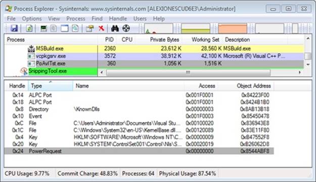
You can then use local kernel debugging to dump the power request object as shown next. Unfortunately, the underlying kernel data structure is not present in the symbol files, so only a hex dump is possible. Nevertheless, the layout of the object is easy to understand: a doubly linked list (the first two pointers), some flags, and then a pointer to the actual request information that the test application supplied, which is highlighted in bold.
kd> dc 8544ABF8
855d01a8 819586c0 85448ea0 00000001 00000007 ......D.........
855d01b8 00000000 00000000 00000000 00000000 ................
855d01c8 b13e9b50
By using the same dump command on the pointer, the power request’s diagnostic reason is visible: “Computation in progress.”
kd> dc b13e9b50
b13e9b50 00000001 8556b030 00000000 00000044 ....0.V.....D...
b13e9b60 00000001 00000014 00000000 80080001 ................
b13e9b70 00000000 006f0043 0070006d 00740075 ....C.o.m.p.u.t.
b13e9b80 00740061 006f0069 0020006e 006e0069 a.t.i.o.n. .i.n.
b13e9b90 00700020 006f0072 00720067 00730065 .p.r.o.g.r.e.s
You can also use the dl (dump list) command on the first pointer in the object’s dump to dump a list of all the power requests on the system, which are linked by the PopPowerRequestObjectList symbol in the kernel. This will let you see power requests that Process Explorer cannot locate, such as those created by drivers.
EXPERIMENT: VIEWING POWER AVAILABILITY REQUESTS WITH POWERCFG
As you saw, dumping power availability requests requires quite a bit of kernel spelunking. Thankfully, the Powercfg utility provides much of the same capabilities in an easier-to-use command-line version. Here’s the output of the utility while browsing a Windows laptop’s share from another machine, while at the same time playing an MP3 file and launching the Poavltst.exe application:
C:\Users\Administrator>powercfg -requests
DISPLAY:
[PROCESS] \Device\HarddiskVolume1\Users\Administrator\PoAvlTst.exe
Computation in progress
[PROCESS] \Device\HarddiskVolume1\Program Files\Windows Media Player\wmplayer.exe
SYSTEM:
[DRIVER] Parallels Audio Controller (x32) (PCI\VEN_8086&DEV_2445&SUBSYS_04001AB8&REV_02\3&
11583659&0&FC)
An audio stream is currently in use.
[DRIVER] \FileSystem\srvnet
An active remote client has recently sent requests to this machine.
[PROCESS] \Device\HarddiskVolume1\Program Files\Windows Media Player\wmplayer.exe
AWAYMODE:
None.
Note the same “Computation in progress” string, as well as the fact that the SMB driver and the audio driver are also requesting power availability and have indicated their reason for doing so. Windows Media Player, on the other hand, continues to use the legacy API, so no information about the reason is available.
Processor Power Management (PPM)
So far, this section has only described the power manager’s control over device (D) and system (S) states, but another important state management must also be performed on a modern operating system: that of the processor (P and C states). Windows implements a processor power manager (PPM) that is responsible for controlling both C states (the idle states of the processor) and P states (the package states of the processor) and for interacting with ACPI firmware as well as a vendor-supplied power management driver, as needed (Intelppm.sys for Intel CPUs, for example). Which states are chosen is usually determined by a combination of internal algorithms and settings that ship in the Windows registry, most of which are tunable by OEMs and administrators. We will show all these tunable policy values later in this section.
Although the exact specifics of PPM are outside the scope of this book and are often hardware-specific, it is worth going into detail about one particular technology that is unique to Windows: core parking. At its essence, core parking is a load-based engine running inside the PPM that makes two sets of decisions:
§ Which particular P states should be entered for a given processor, and how power should be managed across a power domain. A domain is the set of functional units associated with a given processor core (including the core itself), which are all sharing the same clock generator crystal with the same divider, and thus the same frequency. This could be an entire package, half a package, or even just one SMT core with multiple logical processors.
§ Which particular cores should be made unavailable to the scheduler engine (see Chapter 5 in Part 1 for more information on scheduling) in order to reduce attempts to make those selected cores busy again. These selected cores are called parked cores. Note that hard affinity settings will still force the scheduler to pick one of these “unavailable” cores, as described later.
NOTE
In its current implementation, core parking does not rebalance interrupts or shift software timers away from parked cores, but it may do so in the future.
To summarize, core parking aggressively puts processors in their deepest idle (C) states (not necessarily P states) and tries to keep them that way.
Core Parking Policies
Because the power requirements and usage models of desktop machines vary from those of server machines, core parking implements two internal policies for managing processor cores. The first policy, called core parking override, is used by default on client systems. This policy has lower idle thresholds for when to begin parking (that is, it parks more aggressively) and, most importantly, always leaves one thread in an SMT package unparked—in other words, it is responsible for essentially disabling the Hyper-Threading feature found on Intel CPUs until load warrants it. This effect is shown in Figure 8-46: CPU 1 and CPU 3 are parked because they correspond to the second thread of CPU 0’s and CPU 2’s SMT sets.
The second core parking policy is the default behavior, which is to say that it does not make any special considerations for SMT cores. This policy is also paired with less aggressive threshold parameters that are more suitable for server workloads, in which load is usually low during the majority of the time but all processors should be readily available when peaks are hit.
Additionally, the engine is tuned to avoid coalescing processing too much to a single node or subset of nodes. Although consolidating work has energy benefits because less power is distributed or wasted across the system, it now adds significant contention to the memory controller(s), which on a distributed NUMA system would have been less busy because of the scheduler’s ideal node and process-seed selection algorithms. (See Chapter 5 in Part 1 for more information.) Therefore, core parking has to walk an interesting tightrope between reducing power, increasing cache and memory access effectiveness, and reducing contention on node-local resources. An example of this balancing act is that the core parking engine will always keep at least one core available per NUMA node to keep the scheduler’s spreading efforts useful and to help support applications that specifically partition their workloads across nodes through NUMA-aware thread affinity and memory allocation.
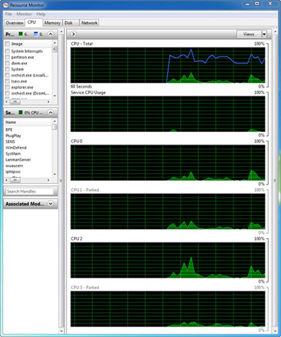
Figure 8-46. Resource Monitor showing core parking effects on SMT systems
Utility Function
Decisions taken by the PPM engine as to whether to modify the power state of a core, as well as which cores to park or unpark, are gated by one primal metric: utility. The utility of a processor represents, in the engine’s view, the load of a given core and is computed by multiplying the average frequency of a core (expressed as a percentage of its maximum) by the busy period of the core (expressed as a percentage of non-idle time). Because two percentages are being multiplied, the maximum utility is 10,000, and almost all the engine’s calculations are done by comparing utility (actually, as we show later, a value derived from utility) with some threshold or average.
NOTE
On modern processors, the average frequency is obtained by invoking the feedback handler associated with the current power domain, which is managed by the vendor-supplied power management driver (such as Intelppm.sys). If a feedback mechanism is not available, the current domain’s frequency is used instead.
Because the utility of a processor can, obviously, change rapidly over time, the engine builds a history of the utilities of each core, as well as a core’s average frequency. It also keeps a running sum of the utilities added up over time, such that the final averaged utility is calculated as the running sum divided by the number of history entries.
EXPERIMENT: VIEWING UTILITY AND FREQUENCY INFORMATION
As with most other PPM-related information, the KPRCB stores information on the current utility as well as the utility history. Furthermore, a few debugger extensions are also available to easily visualize PPM utility information.
When you run the !ppm kernel debugger command, you should see output similar to the following, which shows information for LP 0:
lkd> !ppm
Processor 0
Idle States (3)
0: C1 - intelppm
1: C2 - intelppm
2: C3 - intelppm
Last Used Idle State: 2
Current Frequency: 100%
HardwareFeedback: 55%
Maximum Policy: 100%
Platform Cap: 100%
Minimum Policy: 5%
Minimum Performace: 44%
Minimum Throttle: 5%
Utility: 5400
Highlighted in bold are the three values that were described earlier. The utility of this processor is 5400, and it is currently running at 100 percent of its maximum frequency. The hardware feedback is the average frequency from the feedback handler described previously, which the Intelppm.sys vendor-supplied PPM driver has calculated as 55 percent on this processor.
You can also look at the PPM information for other processors while in a remote debugging session by using the ~ (tilde) command to switch processors. When using the local kernel debugger, you have to dump the KPRCB structure manually and list the .PowerState substructure, as shown in the following output. In this example, the PPM state for LP 1 is dumped.
lkd> !running -i
System Processors: (0000000f)
Idle Processors: (0000000a)
Prcbs Current (pri) Next (pri) Idle
0 8376cd20 87f0b030 (12) 83776380 ................
1 8b404120 8b409800 ( 0) 8b409800 ................
2 8b43a120 86e6ed48 (11) 8b43f800 ................
3 8b470120 8b475800 ( 0) 8b475800 ................
lkd> dt nt!_KPRCB 8b404120 PowerState.
+0x33a0 PowerState :
+0x000 IdleStates : 0x877ff890 _PPM_IDLE_STATES
+0x008 IdleTimeLast : 0xed
+0x010 IdleTimeTotal : 0xadae7baa
...
EXPERIMENT: VIEWING UTILITY AND FREQUENCY HISTORY
If the current core parking policy enables history tracking (which is normally disabled on client systems), you can also see the utility function over time, as well as the frequency. To do so, a different kernel extension has to used, !ppmstate.
Here’s the output of !ppmstate on a server system with core parking enabled:
lkd> !ppmstate
Prcb.PowerState - 0x837700c0
IdleStates: 0x877fe1b0
IdleTimeLast: 0.000.006us (0x860 )
IdleTimeTotal: 11:35.968.474us (0x6bc4ae5f )
IdleAccounting: 0x874d8008
Hypervisor State: 0x0
LastPerfCheck: 13:20.311.497us (0x7becdf55)
PerfDomain: 0x874d9c50
PerfConstraint: 0x874d9cc8
Utility: 0xf6c
PerfHistory: 0x88604300
PerfHistory contents (3 slots, oldest to newest)
Slot Utility Frequency
0 3435 82%
1 10800 108%
2 10900 109%
ThermalConstraint: 100%
PerfActionDPC: 0x83770120
PerfActionMask: 0x0
WmiDispatchPtr: nt!PpmWmiDispatch
WmiInterfaceEnabled: 0x1
CurrentKernelUserTime: 0xc59e
CurrentIdleThreadKTime: 0xb556
Unlike with !ppm, you can also easily use !ppmstate during local kernel debugging because the extension accepts the address of the PowerState field of any KPRCB as a parameter.
When parking and unparking cores, the engine also uses a secondary metric called generic utility. Generic utility is the sum of all the utility functions across all the processors involved in the core parking algorithm. This value is used to gauge the overall activity level of the system and is later converted into a percentage (this will be described later in the algorithm section). Thus, because administrators and users set power policies on a systemwide basis and not on a processor basis (while core parking works at the processor level), generic utility is needed to convert the per-processor utility function into a systemwide representation of utility.
Algorithm Overrides
Since core parking is decoupled from the scheduler (which is what developers have some control over), there are a few scenarios in which the scheduler’s goals must override those of the core parking engine. The first scenario is forced affinitization. When discussing the scheduler’s algorithms in Chapter 5 in Part 1, we noted that the scheduler will sometimes forcefully pick a parked core if it is the ideal processor of a thread and when no unparked cores are available. When this happens, the core parking engine is made aware because the affinity count in the KPRCB’s power state is incremented. Over time, the engine builds a weighted history (as configured by policy) of cores that are repeatedly targeted by hard-affinitized policy and, past a certain threshold, also configured by policy, will cause the engine to react appropriately (this will be described in the algorithm outlined later in this section).
A second override occurs whenever a core is parked (which means that a low, or zero, utility function is expected), yet the calculated utility is past the configured threshold. This override is not controllable through scheduling—in fact, it means that software timer expirations, DPCs, interrupts, and other similar scenarios have caused a parked core to run code outside the scheduler’s purview. When such a situation is detected, the engine reacts differently, as described by the algorithm. Additionally, a history of such “overutilization” is kept, weighted according to the current policy, and it too will cause changes in the algorithm if it reaches a certain policy-configurable threshold.
Look back at Figure 8-46, which showed the Resource Monitor, and notice how CPU 1 and 3, even though parked, still had accumulated some CPU time. Depending on the current policy, one or more of those CPUs could have been considered overutilized.
Increase/Decrease Actions
Whenever the PPM engine is in a situation in which it must increase or decrease the amount of parked cores, or increase or decrease a given core’s performance state, it can apply one of three different actions:
§ Ideal In the ideal model, the engine tries to achieve a performance (frequency) midpoint between the decrease and increase thresholds when choosing a performance state (PERFSTATE_POLICY_CHANGE_IDEAL). When parking or unparking cores, it modifies the parked state of as many cores as needed until the generic utility distribution across unparked cores reaches a value that is just below or above the increase or decrease threshold, respectively (CORE_PARKING_POLICY_CHANGE_IDEAL).
§ Step In the step model, the engine increases or decreases performance (frequency) by one frequency step (if specific frequency steps are exposed through ACPI) or by 5 percent as needed (PERFSTATE_POLICY_CHANGE_STEP). When parking or unparking cores, it always picks just one more core to park or unpark (CORE_PARKING_POLICY_CHANGE_STEP).
§ Rocket In the rocket model, the engine sets the core to its maximum or minimum performance (frequency) state (PERFSTATE_POLICY_CHANGE_ROCKET). When parking, it parks all cores (except one per node, or whatever the current policy specifies), and when unparking, it unparks all cores (CORE_PARKING_POLICY_CHANGE_ROCKET).
Later in this section, when we look at the actual core parking algorithm, we’ll see when these increase and decrease actions are taken.
Thresholds and Policy Settings
Ultimately, what determines whether performance states will be pushed up or down and whether cores will be parked or unparked depends on the thresholds and policy settings that have been set in the registry, configured in particular for each processor vendor and type as well as across client and server systems, AC versus DC power, and different power plans (for example, High Performance, Balanced, or Low Power). Core parking uses the policy settings and thresholds shown in Table 8-10 through Table 8-14.
Table 8-10. Processor Performance Policies (GUID_PROCESSOR_PERF)
|
Policy GUID |
Policy Meaning |
|
INCREASE/DECREASE_THRESHOLD |
Specifies the busy threshold that must be met before changing the processor’s performance state |
|
INCREASE/DECREASE_POLICY |
Specifies the algorithm used to select a new performance state when the ideal performance state does not match the current performance state |
|
INCREASE/DECREASE_TIME |
Specifies the minimum number of performance check intervals since the last performance state change before the performance state can be changed |
|
TIME_CHECK |
Specifies the amount of time that must expire before processor performance states and parked cores may be reevaluated (in milliseconds) |
|
BOOST_POLICY |
Specifies how much processors may opportunistically increase frequency above maximum when allowed by current operating conditions |
|
ALLOW_THROTTLING |
Allows processors to use throttle states (T states) in addition to performance states. |
|
HISTORY |
Specifies the number of processor-performance time-check intervals to use when calculating the average utility |
Table 8-11. Idle State Management Policies (GUID_PROCESSOR_IDLE)
|
Policy GUID |
Policy Meaning |
|
ALLOW_SCALING |
Specifies whether the idle state promotion and demotion values should be scaled based on the current performance state |
|
DISABLE |
Specifies whether idle states should be disabled |
|
TIME_CHECK |
Specifies the time that must elapse since the last idle state promotion or demotion before idle states may be promoted or demoted again (in microseconds) |
|
DEMOTE/PROMOTE_THRESHOLD |
Specifies the busy threshold that must be met before changing the idle state of the processor |
Table 8-12. Core Parking Policies (GUID_PROCESSOR_CORE_PARKING)
|
Policy GUID |
Policy Meaning |
|
INCREASE/DECREASE_THRESHOLD |
Specifies the busy threshold that must be met before changing the number of cores that are unparked |
|
INCREASE/DECREASE_POLICY |
Specifies the algorithm used to select the number of cores to park or unpark when required |
|
MAX/MIN_CORES |
Specifies the number of unparked cores allowed (in a percentage) |
|
INCREASE/DECREASE_TIME |
Specifies the minimum number of performance-check intervals that must elapse before more cores can be parked or unparked |
|
CORE_OVERRIDE |
Ensures that at least one processor remains unparked per core |
|
PERF_STATE |
Specifies what performance state a processor enters when parked |
Table 8-13. Affinity History Policies (GUID_PROCESSOR_CORE_PARKING_AFFINITY_HISTORY)
|
Policy GUID |
Policy Meaning |
|
DECREASE_FACTOR |
Specifies the factor by which to decrease affinity history on each core after the current performance check |
|
THRESHOLD |
Specifies the threshold above which a core is considered to have had significant affinitized work scheduled to it while parked |
|
WEIGHTING |
Specifies the weighting given to each occurrence where affinitized work was scheduled to a parked core |
Table 8-14. Overutilization Policies (GUID_PROCESSOR_CORE_PARKING_OVER_UTILIZATION)
|
Policy GUID |
Policy Meaning |
|
HISTORY_DECREASE_FACTOR |
Specifies the factor by which to decrease the overutilization history on each core after the current performance check |
|
HISTORY_THRESHOLD |
Specifies the threshold above which a core is considered to have been recently overutilized while parked |
|
WEIGHTING |
Specifies the weighting given to each occurrence when a parked core is found to be overutilized |
|
THRESHOLD |
Specifies the busy threshold that must be met before a parked core is considered overutilized |
EXPERIMENT: VIEWING CURRENT CORE PARKING POLICY
When the !popolicy experiment was used in an earlier part of this chapter, it showed you only the system power policy, not the entire policy, which also covers PPM. By using the dt command with the correct structure type, you are also able to see the PPM policy, which covers the policy GUIDs that were shown in the preceding tables. Because the system power policy starts at offset 4, simply subtract 4 from the pointer returned by !popolicy.
lkd> !popolicy
SYSTEM_POWER_POLICY (R.1) @ 0x8377a6c4
lkd> dt nt!_POP_POWER_SETTING_VALUES 8377a6c0
...
+0x10c AllowThrottling : 0 ''
+0x10d PerfHistoryCount : 0x20 ' '
+0x110 PerfTimeCheck : 0xf
+0x114 PerfIncreaseTime : 1
+0x118 PerfDecreaseTime : 1
+0x11c PerfIncreaseThreshold : 0x1e ''
+0x11d PerfDecreaseThreshold : 0xa ''
+0x11e PerfIncreasePolicy : 0x2 ''
+0x11f PerfDecreasePolicy : 0x1 ''
+0x120 PerfMinPolicy : 0x5 ''
+0x121 PerfMaxPolicy : 0x64 'd'
+0x124 PerfBoostPolicy : 0x64
+0x128 CoreParkingIncreaseThreshold : 0x55 'U'
+0x129 CoreParkingDecreaseThreshold : 0x32 '2'
+0x12a CoreParkingMaxCores : 0x64 'd'
+0x12b CoreParkingMinCores : 0xa ''
+0x12c CoreParkingIncreasePolicy : 0 ''
+0x12d CoreParkingDecreasePolicy : 0 ''
+0x130 CoreParkingIncreaseTime : 7
+0x134 CoreParkingDecreaseTime : 0x14
+0x138 CoreParkingAffinityHistoryDecreaseFactor : 0x2 ''
+0x13a CoreParkingAffinityHistoryThreshold : 0x96
+0x13c CoreParkingAffinityWeighting : 0x64
+0x13e CoreParkingOverUtilizationHistoryDecreaseFactor : 0x2 ''
+0x140 CoreParkingOverUtilizationHistoryThreshold : 0x28
+0x142 CoreParkingOverUtilizationWeighting : 0x64
+0x144 CoreParkingOverUtilizationThreshold : 0x3c '<'
+0x145 ParkingCoreOverride : 0x1 ''
+0x146 ParkingPerfState : 0 ''
Another way to see a more limited set of the current policy is to use the !ppmperfpolicy extension, which displays a few of the core policy settings:
lkd> !ppmperfpolicy
MaxPerf: 100%
MinPerf: 5%
TimeCheck: 15 ms
IncreaseTime: 1 time check period(s)
DecreaseTime: 1 time check period(s)
IncreaseThreshold: 30%
DecreaseThreshold: 10%
IncreasePolicy: 2
DecreasePolicy: 1
HistoryCount: 1
BoostPolicy: 100
Performance Check
The algorithm that powers the PPM engine is called the performance check. It is executed by the PpmCheckStart timer callback, which runs periodically based on the current policy’s performance-check interval. The callback acquires the policy lock and sets the initial phase toPpmCheckPhaseInitiate. It calls PpmCheckRun, which runs the algorithm illustrated in the following diagram.
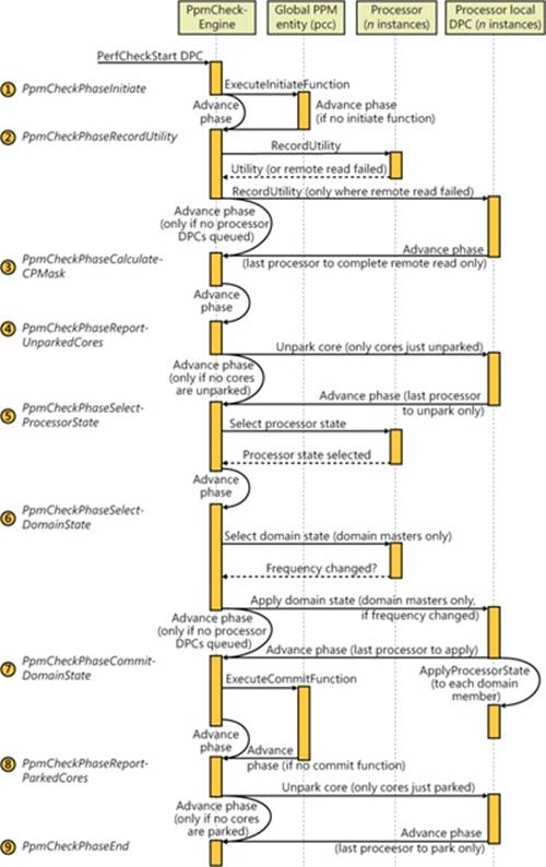
The steps shown in the diagram line up with the PPM_CHECK_PHASE enumeration described in Table 8-15.
Table 8-15. PPM Check Phases
|
Phase Name |
Phase Meaning |
|
PpmCheckPhaseInitiate |
Notifies the vendor-supplied processor power driver that the core parking engine is about to start its performance check |
|
PpmCheckPhaseRecordUtility |
Runs on each processor to calculate the utility function for each core |
|
PpmCheckPhaseCalculateCoreParkingMask |
Using the utility function, current core parking status, affinitization, and overutilization history, organizes all the cores in different sets that are used to determine the best cores to unpark or park. It then performs the unparking of cores |
|
PpmCheckPhaseReportUnparkedCores |
Runs on each unparked processor to notify the scheduler that the core has been unparked |
|
PpmCheckPhaseSelectProcessorState |
Computes the new performance state (target frequency) for each processor based on its parking state and utility |
|
PpmCheckPhaseSelectDomainState |
Selects the best performance state for all the processors in a given domain based on the constraints, and switches to the new processor performance state |
|
PpmCheckPhaseCommitDomainState |
Calls the vendor-supplied processor power driver to commit the new processor performance states |
|
PpmCheckPhaseReportParkedCores |
Runs on each parked processor to notify the scheduler that the core has been unparked. Any ongoing or queued thread activity is moved off the core. |
|
PpmCheckPhaseEnd |
Releases the policy lock and switches the phase to the not-running phase |
|
PpmCheckPhaseNotRunning |
Indicates that the performance check is not running |
Some of the steps in Table 8-15 require a bit more discussion than just a single line. Here are extended details.
Step 2: Recording utility PpmCheckRecordAllUtility enumerates all processors that are part of the core parking engine’s current registered set and determines which ones it will query for utility remotely (that is, from the current core running the check algorithm) or whether it will force a targeted DPC to query utility locally. This determination is made by calling PpmPerfRecordUtility and hinges on the idleness of the core and its current utility value. Because these numbers end up multiplied together, the busier a core becomes (higher utility), the greater the inaccuracy of not having precise frequency measurements becomes, the latter being a side effect of running the check on a remote instead of a local core.
Additionally, while running locally, the function can also check whether the CPU was throttled outside the PPM’s purview, usually indicating broken firmware or drivers (or the existence of a power management strategy that is outside the OS’s view and/or control).
Other than those checks, recording the utility is ultimately about computing the value described earlier in the Utility Function section and keeping track of its history, if the policy enables it.
Step 4: Choosing which cores to unpark The work in this step is done by two functions. The first, PpmPerfCalculateCoreParkingMask, computes how many cores should be unparked and builds a variety of sets that can be used to prioritize unparking:
§ Overutilized cores Those whose utility is higher than the policy threshold, as described in the Algorithm Overrides section.
§ Previously overutilized cores Cores that were overutilized during the previous performance check, as described in the Algorithm Overrides section.
§ Affinitized cores Cores that have been forcefully chosen by the scheduler because of affinitization overrides, also described in the Algorithm Overrides section.
§ Unparked cores Cores that are already unparked.
§ Highly utilized unparked codes Unparked cores with a high utility function.
The function then computes the generic utility (described in the Utility Function section) and determines whether the generic utility percentage (defined as the generic utility divided by the sum of busy frequencies across all cores) is above or below the thresholds specified in the policy. Based on which threshold is crossed, if any, the policy-defined increase/decrease action (described in the Increase/Decrease Actions section earlier) is performed, which results in a count of cores to unpark.
This number, the generic utility, and the sets described earlier are sent to PpmPerfChooseCoresToUnpark, which is responsible for picking which processors should be unparked based on how to spread the generic utility. The algorithm first checks whether the target count is already covered by the already unparked cores, and if so, exits. Otherwise, it keeps unparking cores until the overutilized group is enough to handle the remaining unpark requests. In other words, overutilized cores always become unparked, and the algorithm must pick which other, nonoverutilized cores, should also be unparked.
To do so, it runs the following elimination round in the specified order. Each step is taken only if it results in a nonzero intersection (if other candidates exist):
§ Remove any processors that are not already overutilized
§ Remove any processors that are not already highly utilized
§ Remove any processors that are not already unparked
§ Remove any processors that were not previously overutilized
§ Remove any processors that do not have forced affinitized threads
In the most optimistic scenario, this results in a set of overutilized, highly utilized, previously overutilized, and forced-affinitized processors. In other words, this set contains the processors least likely to benefit from parking in the first place. From this set, the core parking engine picks the lowest processor number and then enters a new round of elimination until the conditions specified earlier match.
At the end of the algorithm, after all overutilized cores and noneliminated cores have been unparked, the generic utility is balanced (distributed equally) across all the newly unparked processors.
Step 5: Selecting processor state PpmPerfSelectProcessorStates enumerates each processor that’s part of this run and calls PpmPerfSelectProcessorState for each one. In this case, the algorithm can run remotely (without requiring a local DPC callback on the core) because all the data is available from the KPRCB. The purpose of this function is to decide which processor state makes the most sense for the given processor, based on its expected utility function.
The first check is to verify whether this processor has been selected for parking in step 3. If it was selected, the target power state for parked cores, based on policy, is selected. Three possibilities exist:
§ Lightest The parked processor is targeted to run at 100 percent of its frequency.
§ Deepest The parked processor is targeted to run at 1 percent of its frequency.
§ No Preference The parked processor will be treated just like any other processor and continue the regular algorithm.
Assuming that the algorithm does continue, the next step is to compute the busyness of the processor. Since the utility function is equal to the busyness percentage multiplied by the average frequency, this means that the busyness of the processor is its utility divided by its average frequency. This busyness is then compared with the increase and/or decrease thresholds specified by policy, and one of the three possible actions are taken (ideal, step, or rocket, described earlier in Increase/Decrease Actions).
The domain performance handler callback (owned by the vendor-supplied processor driver) is then called with the new target frequencies and with whether throttling was allowed by the policy.
Step 6: Selecting domain state As shown in the previous illustration, this step is also composed of a few substeps. The first, done remotely, is performed by PpmPerfSelectDomainStates, which picks the domain masters and calls PpmPerfSelectDomainState to run on them. This function iterates over all the processors in the domain and picks the one with the highest performance state (the highest desired frequency). It then sets this as the desired frequency for the entire domain.
Now that each domain master has selected its domain state, control returns to PpmPerfSelectDomainStates, which queues a local DPC for all of the domain masters that is implemented by PpmPerfApplyDomainState. This is the second step. This function takes into consideration the valid P states (and T states, if throttling is enabled by policy) and trims any states outside the current processor constraints, which include percentage caps and thermal caps. When it has picked the best target frequency (and consulted with the domain performance handler callback), it queues a DPC to all the processors in each domain to apply the selected performance state to each core.
In this third step, implemented by the PpmPerfApplyProcessorState DPC routine, the domain’s performance handler callback is called to switch states. Finally, PpmScaleIdleStateValues is called. If idle scaling is enabled by policy, this function scales the processor’s C states (idle states) according to the promotion/demotion percentages specified in the policy.
EXPERIMENT: VIEWING CURRENT PPM CHECK INFORMATION
The kernel debugger includes an extension, !ppmcheck, which you can use to check whether core parking is enabled and which cores are currently parked, as well as the internal performance checking algorithm state. Here’s a sample output of the extension:
lkd> !ppmcheck
PpmCheckArmed: TRUE
PpmCheckStartDpc: 0x8377aa58
PpmCheckDpc: 0x8377aa78
PpmCheckTimer: 0x8377aa30
PpmCheckMakeupCount: -
PpmCheckLastExecutionTime: -
PpmCheckTime: 08:40.738.783us (0x50a26d3d)
PpmCheckPhase: 9
PpmCheckRegistered: 0x8376b408
{[0000000F]}
PpmPerfStatesRegistered: 0x8376b390
{[0000000F]}
CoreParkingEnabled: TRUE
CoreParkingMask: 0x8376b35c
{[0000000A]}
You can also see the complete PPM information for a given processor by looking at the PRCB’s PowerState field and further drilling down into the Domain and PerfConstraint members. This will show you the selected domain performance state, the constraints (thermal and frequency caps), and other accounting information. You can use dt nt!_KPRCB @$prcb PowerState to see this information for the current PRCB:
+0x33a0 PowerState :
+0x000 IdleStates : 0x877fe1b0 _PPM_IDLE_STATES
+0x008 IdleTimeLast : 0xa6
+0x010 IdleTimeTotal : 0x97789fc9
+0x018 IdleTimeEntry : 0
+0x020 IdleAccounting : 0x874d8008 _PROC_IDLE_ACCOUNTING
+0x024 Hypervisor : 0 ( ProcHypervisorNone )
+0x028 PerfHistoryTotal : 0
+0x02c ThermalConstraint : 0x64 'd'
+0x02d PerfHistoryCount : 0x1 ''
+0x02e PerfHistorySlot : 0 ''
+0x02f Reserved : 0 ''
+0x030 LastSysTime : 0xfa86
+0x034 WmiDispatchPtr : 0x837c5464
+0x038 WmiInterfaceEnabled : 0n1
+0x040 FFHThrottleStateInfo : _PPM_FFH_THROTTLE_STATE_INFO
+0x060 PerfActionDpc : _KDPC
+0x080 PerfActionMask : 0n0
+0x088 IdleCheck : _PROC_IDLE_SNAP
+0x098 PerfCheck : _PROC_IDLE_SNAP
+0x0a8 Domain : 0x874d9c50 _PROC_PERF_DOMAIN
+0x0ac PerfConstraint : 0x874d9cc8 _PROC_PERF_CONSTRAINT
+0x0b0 Load : (null)
+0x0b4 PerfHistory : (null)
+0x0b8 Utility : 0xba8
+0x0bc OverUtilizedHistory : 0
+0x0c0 AffinityCount : 0
+0x0c4 AffinityHistory : 0
lkd> dt 0x874d9c50 _PROC_PERF_DOMAIN
nt!_PROC_PERF_DOMAIN
+0x000 Link : _LIST_ENTRY [ 0x8376b39c - 0x8376b39c ]
+0x008 Master : 0x8b470120 _KPRCB
+0x00c Members : _KAFFINITY_EX
+0x018 FeedbackHandler : 0x93d19d08 unsigned char +0
+0x01c GetFFHThrottleState : 0x93d1804e void +0
+0x020 BoostPolicyHandler : 0x93d18104 void +0
+0x024 PerfSelectionHandler : 0x93d19bee unsigned long +0
+0x028 PerfHandler : 0x93d19d40 void +0
+0x02c Processors : 0x874d9cc8 _PROC_PERF_CONSTRAINT
+0x030 PerfChangeTime : 0xaa90c1ed
+0x038 ProcessorCount : 4
+0x03c PreviousFrequencyMhz : 0x532
+0x040 CurrentFrequencyMhz : 0xa65
+0x044 PreviousFrequency : 0x31
+0x048 CurrentFrequency : 0x64
+0x04c CurrentPerfContext : 0
+0x050 DesiredFrequency : 0x64
+0x054 MaxFrequency : 0xa65
+0x058 MinPerfPercent : 0x2c
+0x05c MinThrottlePercent : 5
+0x060 MaxPercent : 0x64
+0x064 MinPercent : 5
+0x068 ConstrainedMaxPercent : 0x64
+0x06c ConstrainedMinPercent : 0x2c
+0x070 Coordination : 0x1 ''
+0x074 PerfChangeIntervalCount : 0n0
lkd> dt 0x874d9cc8 _PROC_PERF_CONSTRAINT
ntdll!_PROC_PERF_CONSTRAINT
+0x000 Prcb : 0x8376cd20 _KPRCB
+0x004 PerfContext : 0x877febe0
+0x008 PercentageCap : 0x64
+0x00c ThermalCap : 0x64
+0x010 TargetFrequency : 0x36
+0x014 AcumulatedFullFrequency : 0x46c3df
+0x018 AcumulatedZeroFrequency : 0xd51828
+0x01c FrequencyHistoryTotal : 0
+0x020 AverageFrequency : 0x36
Conclusion
The I/O system defines the model of I/O processing on Windows and performs functions that are common to or required by more than one driver. Its chief responsibility is to create IRPs representing I/O requests and to shepherd the packets through various drivers, returning results to the caller when an I/O is complete. The I/O manager locates various drivers and devices by using I/O system objects, including driver and device objects. Internally, the Windows I/O system operates asynchronously to achieve high performance and provides both synchronous and asynchronous I/O capabilities to user-mode applications.
Device drivers include not only traditional hardware device drivers but also file system, network, and layered filter drivers. All drivers have a common structure and communicate with one another and the I/O manager by using common mechanisms. The I/O system interfaces allow drivers to be written in a high-level language to lessen development time and to enhance their portability. Because drivers present a common structure to the operating system, they can be layered one on top of another to achieve modularity and reduce duplication between drivers. Also, all Windows device drivers should be designed to work correctly on multiprocessor systems.
Finally, the role of the PnP manager is to work with device drivers to dynamically detect hardware devices and to build an internal device tree that guides hardware device enumeration and driver installation. The power manager works with device drivers to move devices into low-power states when applicable to conserve energy and prolong battery life.
Three more upcoming chapters will cover additional topics related to the I/O system: storage management, file systems (including details on the NTFS file system), and the cache manager.
All materials on the site are licensed Creative Commons Attribution-Sharealike 3.0 Unported CC BY-SA 3.0 & GNU Free Documentation License (GFDL)
If you are the copyright holder of any material contained on our site and intend to remove it, please contact our site administrator for approval.
© 2016-2026 All site design rights belong to S.Y.A.