Windows Internals, Sixth Edition, Part 2 (2012)
Chapter 9. Storage Management
Storage management defines the way that an operating system interfaces with nonvolatile storage devices and media. The term storage encompasses many different devices, including optical media, USB flash drives, floppy disks, hard disks, solid state disks (SSDs), network storage such as iSCSI, storage area networks (SANs), and virtual storage such as VHDs (virtual hard disks). Windows provides specialized support for each of these classes of storage media. Because our focus in this book is on the kernel components of Windows, in this chapter we’ll concentrate on just the fundamentals of the hard disk storage subsystem in Windows, which includes support for external disks and flash drives. Significant portions of the support Windows provides for removable media and remote storage (offline archiving) are implemented in user mode.
In this chapter, we’ll examine how kernel-mode device drivers interface file system drivers to disk media, discuss how disks are partitioned, describe the way volume managers abstract and manage volumes, and present the implementation of multipartition disk-management features in Windows, including replicating and dividing file system data across physical disks for reliability and for performance enhancement. We’ll also describe how file system drivers mount volumes they are responsible for managing, and we’ll conclude by discussing drive encryption technology in Windows and support for automatic backups and recovery.
Storage Terminology
To fully understand the rest of this chapter, you need to be familiar with some basic terminology:
§ Disks are physical storage devices such as a hard disk, CD-ROM, DVD, Blu-ray, solid state disk (SSD), or flash.
§ A disk is divided into sectors, which are addressable blocks of fixed size. Sector sizes are determined by hardware. Most hard disk sectors are 512 bytes (but are moving to 4,096 bytes), and CD-ROM sectors are typically 2,048 bytes. For more information on moving to 4,096-byte sectors, see http://support.microsoft.com/kb/2510009.
§ Partitions are collections of contiguous sectors on a disk. A partition table or other disk-management database stores a partition’s starting sector, size, and other characteristics and is located on the same disk as the partition.
§ Simple volumes are objects that represent sectors from a single partition that file system drivers manage as a single unit.
§ Multipartition volumes are objects that represent sectors from multiple partitions and that file system drivers manage as a single unit. Multipartition volumes offer performance, reliability, and sizing features that simple volumes do not.
Disk Devices
From the perspective of Windows, a disk is a device that provides addressable long-term storage for blocks of data, which are accessed using file system drivers. In other words, each byte on the disk does not have its own address, but each block does have an address. These blocks are known as sectors and are the basic unit of storage and transfer to and from the device (in other words, all transfers must be a multiple of the sector size). Whether the device is implemented using rotating magnetic media (hard disk or floppy disk) or solid state memory (flash disk or thumb drive) is irrelevant.
Windows supports a wide variety of interconnect mechanisms for attaching a disk to a system, including SCSI, SAS (Serial Attached SCSI), SATA (Serial Advanced Technology Attachment), USB, SD/MMC, and iSCSI.
Rotating Magnetic Disks
The typical disk drive (often referred to as a hard disk) is built using one or more rigid rotating platters covered in a magnetic material. An arm containing a head moves back and forth across the surface of the platter reading and writing bits that are stored magnetically.
Disk Sector Format
While the disk interconnect mechanisms have been evolving since IBM introduced hard disks in 1956 and have become faster and more intelligent, the underlying disk format has changed very little, except for annual increases in areal density (the number of bits per square inch). Since the inception of disk drives, the data portion of a disk sector has typically been 512 bytes.
Disk storage areal density has increased from 2,000 bits per square inch in 1956 to over 650 billion bits per square inch in 2011, with most of that gain coming in the last 15 years. Disk manufacturers are reaching the physical limits of current magnetic disk technology, so they are changing the format of the disks: increasing the sector size from 512 bytes to 4,096 bytes, and changing the size of the error correcting code (ECC) from 50 bytes to 100 bytes. This new disk format is known as the advanced format. The size of the advanced format sector was chosen because it matches the x86 page size and the NTFS cluster size. The advanced format provides about 10 percent greater capacity by reducing the amount of overhead per sector (everything except the data area is overhead) and through better error correcting capabilities. (A single 100-byte ECC is better than eight 50-byte ECCs). The downside to advanced format disks is potentially wasted space for small files, but as you’ll see in Chapter 12, NTFS has a mechanism for efficiently storing small files.
Advanced format disks provide an emulation mechanism (known as 512e) for legacy operating systems that understand only 512-byte sectors. With 512e, the host does not know that the disk supports 4,096-byte sectors; it continues to read and write 512-byte sectors (called logical blocks). The disk’s controller will translate a logical block number into the correct physical sector. For example, if the host issues a read request for logical block number 6, then the disk controller will read physical sector number 0 into its internal buffer and return only the 512-byte portion corresponding to logical block 6 to the host, as shown in Figure 9-1.
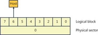
Figure 9-1. Advanced format sector with 512e
Writes are a little more complicated in that they require the disk’s controller to perform a read-modify-write operation, as shown in Figure 9-2.
1. The host writes logical block 6 to the controller.
2. The controller maps logical block 6 to physical sector 0 and reads the entire sector into the controller’s memory.
3. The controller copies logical block 6 into its position within the copy of the physical sector in the controller’s memory.
4. The controller writes the 4,096-byte physical sector from memory back to the disk.
Obviously, there is a performance penalty associated with using 512e, but advanced format disks will still work with legacy operating systems.
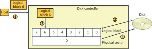
Figure 9-2. 512e read-modify-write operation
Windows supports native 4,096-byte advance format sectors, so there is no additional read-modify-write overhead. As you will see in Chapter 12, NTFS was written to support sectors of more than 512 bytes and by default issues disk I/Os using a 4,096-byte cluster. The Windows cache manager (see Chapter 11) will attempt to reduce the penalty of applications assuming 512-byte sectors; however, applications should be upgraded to query the size of a disk’s sectors (by issuing an IOCTL_STORAGE_QUERY_PROPERTY I/O request and examining the returned BytesPerPhysicalSector value) and not assume 512-byte sectors when performing sector I/O. It is very important that partitioning tools understand the size of a disk’s physical sectors and align partitions to physical sector boundaries because partitions must be an integral number of physical sectors.
Solid State Disks
Recently, the cost of manufacturing flash memory has decreased to the point where manufacturers are building storage subsystems with a disk-type interface, calling the device a solid state disk (SSD) or flash disk. As far as Windows is concerned, an SSD is a disk, but there are some important differences between a rotating disk and an SSD that Windows has to support. Before getting into the details of how Windows supports SSDs, let’s look at how an SSD is implemented.
Flash memory in some respects is very similar to a computer’s RAM (random access memory), except that flash memory does not lose its contents when the power is removed, which means that flash memory is nonvolatile. The most common types of flash memory are NOR and NAND. NOR flash memory is operationally the closest to RAM in that each byte is individually addressable, while NAND flash memory is organized into blocks, like a disk. Typically, NOR-type flash memory is used to hold the BIOS on your computer’s motherboard, and NAND-type flash memory is used in SSDs.
The most important difference between flash memory and RAM is that RAM can be read and written an almost infinite number of times, while flash memory can be overwritten something less than 100,000 times. (Depending on the type of flash memory, it may be as few as 1,000 times). In effect, flash memory wears out, so flash memory should be treated more like media with a limited lifetime (such as a floppy disk) than RAM or a magnetic disk. Another major difference between flash memory and RAM is that flash memory cannot be updated in place; a block must be erased before it can be written (even for NOR-type flash memory). Flash memory is significantly faster than magnetic disks (usually by a factor of 100,000, or so; access time: 50 nanoseconds versus 5 milliseconds), but it is slower than RAM (usually by a factor of 50). From a practical perspective, memory access time is not the whole story because flash memory is not on the system memory bus. Instead, it sits behind a disk-type controller interface on an I/O bus, so in reality the difference between flash and magnetic disks may be on the order of only 1,000 times faster, and in some workloads a rotating magnetic disk can outperform a low-end SSD.
NAND-Type Flash Memory
NAND-type flash memory is most commonly used in SSDs, so that is what we will examine in detail. NAND-type flash comes in two types:
§ Single-level cell (SLC) stores 1 bit per internal cell, has a higher number of program/erase cycles (on the order of 100,000), and is significantly faster than multilevel cell (MLC), but it is much more expensive than MLC.
§ Multilevel cell (MLC) stores multiple bits per internal cell and is significantly cheaper than SLC. MLC needs more ECC bits than SLC, has fewer erase cycles (~5,000), and consumes more power than SLC.
NAND-type flash is typically organized into 4,096-byte pages (which may be exposed as eight 512-byte sectors or a single 4,096-byte sector), which are the smallest readable or writable units, and the pages are grouped into blocks of 64 to 1,024 pages, with thousands of blocks per chip. As with a magnetic disk, there is overhead on each page, with ECC, page health, and spare bits. The block is the smallest erasable unit, so to change a single sector within a page requires that the entire block be erased and then rewritten. (Flash cells can be written only after they have been erased.) This means that writing a sector to an empty block is very fast, but if there is not an available empty block, the controller has to perform the following actions:
1. Read the entire block into the controller’s internal RAM.
2. Erase the block in the flash memory.
3. Update the block in RAM with the contents of the new sector.
4. Write the entire block to the flash memory.
Notice that what started as a write to a sector (512 bytes) became a write of an entire block. For this example, if we assume 128 pages in a block and a completely full block, then the write would take 1,023 times longer (the block contains 1,024 sectors) than the write of a single sector to an empty block. This example is a worst case and is decidedly not the norm, but it illustrates an important aspect of SSDs: as more and more of the SSD’s memory is consumed, it will have to rewrite substantially more data than a single sector. In effect, SSDs slow down as they fill up. This has important implications that are addressed in the next section, File Deletion and the Trim Command.
As a block wears out, eventually it will fail to erase. Also, the more a block is erased and rewritten, the slower it becomes (a result of the physics behind how flash memory is implemented). This means that an SSD will only get slower as you use it—even on an empty block. For example, on a 1-GB USB MLC flash disk with 128 pages per block (giving us 2,048 blocks), erasing and writing one block per second would wear out all the blocks in 23.7 days (assuming a maximum of 1,000 erase cycles per block, which is typical for the cheaper flash disks). Erasing and writing the same block once per second will wear out that block in only 16.6 minutes! SSDs typically have spare blocks held in reserve (often 20 percent of the SSD’s capacity) so that if a block wears out, the data is moved to a spare block. Clearly, flash memory cannot be used the same way as RAM or a magnetic disk.
The flash memory controller implements a technique called wear-leveling to spread the wear (erases) across the SSD. Wear-leveling depends on the fact that most of the data that you write to a disk is static; that is, it does not change often (it is usually read frequently, but that doesn’t cause wear). Of course, there is also dynamic data (such as log files) that changes frequently. There are many different types of wear-leveling algorithms, but describing them is beyond the scope of this book. The important concept to understand about wear-leveling is that the controller will move data around within the flash memory in an attempt to spread writes across all the flash memory, thus prolonging the overall life of the SSD. An implication of wear-leveling is that more blocks are subjected to more frequent program/erase cycles in an attempt to extend the overall life of the flash memory, but when the drive fails (as they all do), then more blocks will fail at the same time. Keep in mind that the SSD industry is moving toward the point where SSDs will advertise their health more explicitly, and at the point of impending write failure they will become read-only drives.
File Deletion and the Trim Command
The file system keeps track of which areas of a disk are currently in use for each file, and when a file is deleted it does not zero all the areas on the disk that contained the file—if it did, then deleting a large file would take longer than deleting a small file, and file undelete utilities would not work. Instead, the file system driver will mark those areas of the disk as available in its data structures (usually referred to as metadata; see Chapter 12 for more information). This is not a problem for magnetic disks because they read and write sectors natively, but SSDs do not read and write sectors natively (recall that the size of the writable unit, the page, is much smaller than the size of the erasable unit, the block).
SSDs have to manage the contents of pages and blocks when updating a sector. This becomes a huge problem because the SSD does not know that the contents of a page are free unless it has been erased. The SSD would continue to preserve “deleted” data when updating a sector or during wear-leveling, reducing the amount of free space available to the SSD controller. The end result would be that the speed of the SSD would degrade up to the point at which all sectors have been accessed (at least once), and the only way to speed it up again would be to erase the entire drive. This is exactly the behavior that existed in early SSDs.
The solution to this problem was the introduction of the trim command to the SSD’s controller. The file system detects that the SSD supports the trim command by sending the I/O request IOCTL_STORAGE_QUERY_PROPERTY with the property ID StorageDeviceTrimPropertydown the storage stack (covered later in this chapter). When a file is deleted or truncated on a disk that supports the trim command, the file system sends the list of sectors that the file occupied to the disk driver, using the I/O request IOCTL_STORAGE_MANAGE_DATA_SET_ATTRIBUTES with the action parameter DeviceDsmAction_Trim. When the disk driver receives this I/O request, it sends a trim command to the SSD, notifying the SSD that those sectors are now free and may be erased and repurposed at the SSD’s convenience. This lets the SSD reclaim those sectors during an update or wear-leveling operation, thereby improving the performance of the SSD. Note that the trim command cannot be queued internally within the SSD’s controller and executes synchronously, which may manifest as a noticeable pause when a large file is being deleted.
While Windows does support SSDs, Microsoft recommends that they be backed up frequently if they are being used for important data. A standard disk defragmenter should never be used on an SSD because it will wear out the flash very quickly. The Windows defragmenter will not attempt to defragment an SSD. (Defragmenting an SSD isn’t generally useful because file fragmentation does not slow down access to a file on an SSD in the same way that it does on a magnetic disk.) As we’ll see in Chapter 12, NTFS was not designed with short-lived (flash memory) disks in mind, and it frequently issues lots of small writes to its transaction log, which is important for increasing reliability but causes additional wear to the flash memory. Using an SSD as your C: drive may drastically increase the speed of your system, but understand that the SSD will wear out before a magnetic disk would.
NOTE
High-end magnetic disks can outperform low-end SSDs in some cases because many low-end SSDs perform poorly for small, random writes, which is a characteristic of the typical Windows workload.
Disk Drivers
The device drivers involved in managing a particular storage device are collectively known as a storage stack. Figure 9-3 shows each type of driver that might be present in a stack and includes a brief description of its purpose. This chapter describes the behavior of device drivers below the file system layer in the stack. (The file system driver operation is described in Chapter 12.)
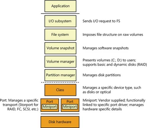
Figure 9-3. Windows storage stack
Winload
As you saw in Chapter 4, “Management Mechanisms,” in Part 1, Winload is the Windows operating system file that conducts the first portion of the Windows boot process. Although Winload isn’t technically part of the storage stack, it is involved with storage management because it includes support for accessing disk devices before the Windows I/O system is operational. Winload resides on the boot volume; the boot-sector code on the system volume executes Bootmgr. Bootmgr reads the Boot Configuration Database (BCD) from the system volume or EFI firmware and presents the computer’s boot choices to the user. Bootmgr translates the name of the BCD boot entry that a user selects to the appropriate boot partition and then runs Winload to load the Windows system files (starting with the registry, Ntoskrnl.exe and its dependencies, and the boot drivers) into memory to continue the boot process. In all cases, Winload uses the computer firmware to read the disk containing the system volume.
Disk Class, Port, and Miniport Drivers
During initialization, the Windows I/O manager starts the disk storage drivers. Storage drivers in Windows follow a class/port/miniport architecture, in which Microsoft supplies a storage class driver that implements functionality common to all storage devices and a storage port driver that implements class-specific functionality common to a particular bus—such as SATA (Serial Advanced Technology Attachment), SAS (Serial Attached SCSI), or Fibre Channel—and OEMs supply miniport drivers that plug into the port driver to interface Windows to a particular controller implementation.
In the disk storage driver architecture, only class drivers conform to the standard Windows device driver interfaces. Miniport drivers use a port driver interface instead of the device driver interface, and the port driver simply implements a collection of device driver support routines that interface miniport drivers to Windows. This approach simplifies the role of miniport driver developers and, because Microsoft supplies operating system–specific port drivers, allows driver developers to focus on hardware-specific driver logic. Windows includes Disk (%SystemRoot%\System32\Drivers\Disk.sys), a class driver that implements functionality common to all disks. Windows also provides a handful of disk port drivers. For example, %SystemRoot%\System32\Drivers\Scsiport.sys is the legacy port driver for disks on SCSI buses (Scsiport is now deprecated and should no longer be used), and %SystemRoot%\System32\Drivers\Ataport.sys is a port driver for IDE-based systems. Most newer drivers use the %SystemRoot%\System32\Drivers\Storport.sys port driver as a replacement for Scsiport.sys. Storport.sys is designed to realize the high performance capabilities of hardware RAID and Fibre Channel adapters. The Storport model is similar to Scsiport, making it easy for vendors to migrate existing Scsiport miniport drivers to Storport. Miniport drivers that developers write to use Storport take advantage of several of Storport’s performance enhancing features, including support for the parallel execution of I/O initiation and completion on multiprocessor systems, a more controllable I/O request-queue architecture, and execution of more code at lower IRQL to minimize the duration of hardware interrupt masking. Storport also includes support for dynamic redirection of interrupts and DPCs to the best (most local) NUMA node (often referred to as NUMA I/O) on systems that support it.
Both the Scsiport.sys and Ataport.sys drivers implement a version of the disk scheduling algorithm known as C-LOOK. The drivers place disk I/O requests in lists sorted by the first sector (also known as the logical block address, or LBA) at which an I/O request is directed. They use the KeInsertByKeyDeviceQueue and KeRemoveByKeyDeviceQueue functions (documented in the Windows Driver Kit) representing I/O requests as items and using a request’s starting sector as the key required by the functions. When servicing requests, the drivers proceed through the list from lowest sector to highest. When they reach the end of the list the drivers start back at the beginning, since new requests might have been inserted in the meantime. If disk requests are spread throughout a disk this approach results in the disk head continuously moving from near the outermost cylinders of the disk toward the innermost cylinders. Storport.sys does not implement disk scheduling because it is commonly used for managing I/Os directed at storage arrays where there is no clearly defined notion of a disk start and end.
Windows ships with several miniport drivers. On systems that have at least one ATAPI-based IDE device, %SystemRoot%\System32\Drivers\Atapi.sys, %SystemRoot%\System32\Drivers\Pciidex.sys, and %SystemRoot%\System32\Drivers\Pciide.sys together provide miniport functionality. Most Windows installations include one or more of the drivers mentioned.
iSCSI Drivers
The development of iSCSI as a disk transport protocol integrates the SCSI protocol with TCP/IP networking so that computers can communicate with block-storage devices, including disks, over IP networks. Storage area networking (SAN) is usually architected on Fibre Channel networking, but administrators can leverage iSCSI to create relatively inexpensive SANs from networking technology such as Gigabit Ethernet to provide scalability, disaster protection, efficient backup, and data protection. Windows support for iSCSI comes in the form of the Microsoft iSCSI Software Initiator, which is available on all editions of Windows.
The Microsoft iSCSI Software Initiator includes several components:
§ Initiator This optional component, which consists of the Storport port driver and the iSCSI miniport driver (%SystemRoot%\System32\Drivers\Msiscsi.sys), uses the TCP/IP driver to implement software iSCSI over standard Ethernet adapters and TCP/IP offloaded network adapters.
§ Initiator service This service, implemented in %SystemRoot%\System32\Iscsicli.exe, manages the discovery and security of all iSCSI initiators as well as session initiation and termination. iSCSI device discovery functionality is implemented in %SystemRoot%\System32\Iscsium.dll. An important goal of the iSCSI service is to provide a common discovery/management infrastructure irrespective of the protocol driver being used, which could be the Microsoft software initiator driver or an HBA driver (host bus adapter; iSCSI protocol handling offloaded to hardware, which is generally Storport miniports). In this context, iSCSI also provides Win32 and WMI interfaces for management and configuration. The iSCSI initiator service supports four discovery mechanisms:
§ iSNS (Internet Storage Name Service) The addresses of the iSNS servers that the iSCSI initiator service will use are statically configured using the iscsicli AddiSNSServer command.
§ SendTargets The SendTarget portals are statically configured using the iscsicli AddTargetPortal command.
§ Host Bus Adapter Discovery iSCSI HBAs that conform to the iSCSI initiator service interfaces can participate in target discovery by means of an interface between the HBA and the iSCSI initiator service.
§ Manually Configured Targets iSCSI targets can be manually configured using the iscsicli AddTarget command or with the iSCSI Control Panel applet.
§ Management applications These include Iscsicli.exe, a command-line tool for managing iSCSI device connections and security, and the corresponding Control Panel application.
Some vendors produce iSCSI adapters that offload the iSCSI protocol to hardware. The initiator service works with these adapters, which must support the iSNS protocol (RFC 4171), so that all iSCSI devices, including those discovered by the initiator service and those discovered by iSCSI hardware, are recognized and managed through standard Windows interfaces.
Multipath I/O (MPIO) Drivers
Most disk devices have one path—or series of adapters, cables, and switches—between them and a computer. Servers requiring high levels of availability use multipathing solutions, where more than one set of connection hardware exists between the computer and a disk so that if a path fails, the system can still access the disk via an alternate path. Without support from the operating system or disk drivers, however, a disk with two paths, for example, appears as two different disks. Windows includes multipath I/O support to manage multipath disks as a single disk. This support relies on built-in or third-party drivers called device-specific modules (DSMs) to manage details of the path management—for example, load balancing policies that choose which path to use for routing requests and error detection mechanisms to inform Windows when a path fails. Built into Windows is a DSM (%SystemRoot%\System32\Drivers\Msdsm.sys) that works with all storage arrays that conform to the industry standard (T10 SPC4 specification) definition of asymmetric logical unit arrays (ALUA). Storage array vendors must write their own DSM if the modules are not ALUA-compliant. Support for writing a DSM is now part of the Windows Driver Kit. MPIO support is available as an optional feature for Windows Server 2008/R2, which must be installed via Server Manager. MPIO is not available on client editions of Windows.
In a Windows MPIO storage stack, shown in Figure 9-4, the disk driver includes functionality for MPIO devices, which in older versions of Windows was a separate driver (Mpdev.sys). Disk.sys is responsible for claiming ownership of device objects representing multipath disks—so that it can ensure that only one device object is created to represent those disks—and for locating the appropriate DSM to manage the paths to the device. The Multipath Bus Driver (%SystemRoot%\System32\Drivers\Mpio.sys) manages connections between the computer and the device, including power management for the device. Disk.sys informs Mpio.sys of the presence of the devices for it to manage. The port driver (and the miniport drivers beneath it) for a multipath disk is not MPIO-aware and does not participate in anything related to handling multiple paths. There are a total of three disk device stacks, two representing the physical paths (children of the adapter device stacks) and one representing the disk (child of the MPIO adapter device stack). When the latter receives a request, it uses the DSM to determine which path to forward that request to. The DSM makes the selection based on policy, and the request is sent to the corresponding disk device stack, which in turn forwards it to the device via the corresponding adapter.
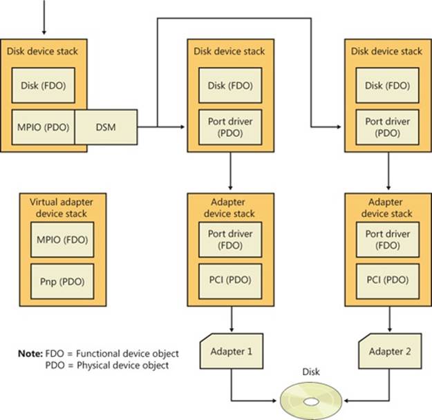
Figure 9-4. Windows MPIO storage stack
The system crash dump and hibernation mechanisms operate in a very restricted environment (very little operating system and device driver support). Drivers operating in this environment have some knowledge of MPIO, but there are limits as to what can be supported. For example, if one path to a disk is down, Windows can failover only to another disk that is controlled by the same miniport driver.
MPIO configuration management is provided through MPClaim (%SystemRoot%\System32\Mpclaim.exe) and a disk properties tab in Explorer.
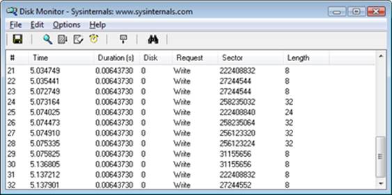
EXPERIMENT: WATCHING PHYSICAL DISK I/O
Diskmon from Windows Sysinternals (www.microsoft.com/technet/sysinternals) uses the disk class driver’s Event Tracing for Windows (or ETW, which is described in Chapter 3, “System Mechanisms,” in Part 1) instrumentation to monitor I/O activity to physical disks and display it in a window. Diskmon updates once a second with new data. For each operation, Diskmon shows the time, duration, target disk number, type and offset, and length, as you can see in the screen shown here.
Disk Device Objects
The Windows disk class driver creates device objects that represent disks. Device objects that represent disks have names of the form \Device\HarddiskX\DRX; the number that identifies the disk replaces both Xs. To maintain compatibility with applications that use older naming conventions, the disk class driver creates symbolic links with Windows NT 4–formatted names that refer to the device objects the driver created. For example, the volume manager driver creates the link \Device\Harddisk0\Partition0 to refer to \Device\Harddisk0\DR0, and \Device\Harddisk0\Partition1 to refer to the first partition device object of the first disk. For backward compatibility with applications that expect legacy names, the disk class driver also creates the same symbolic links in Windows that represent physical drives that it would have created on Windows NT 4 systems. Thus, for example, the link \GLOBAL??\PhysicalDrive0 references \Device\Harddisk0\DR0. Figure 9-5 shows the WinObj utility from Sysinternals displaying the contents of a Harddisk directory for a basic disk. You can see the physical disk andpartition device objects in the pane at the right.

Figure 9-5. WinObj showing a Harddisk directory of a basic disk
As you saw in Chapter 3 in Part 1, the Windows API is unaware of the Windows object manager namespace. Windows reserves two groups of namespace subdirectories to use, one of which is the \Global?? subdirectory. (The other group is the collection of per-session \BaseNamedObjects subdirectories, which are covered in Chapter 3.) In this subdirectory, Windows makes available device objects that Windows applications interact with—including COM and parallel ports—as well as disks. Because disk objects actually reside in other subdirectories, Windows uses symbolic links to connect names under \Global?? to objects located elsewhere in the namespace. For each physical disk on a system, the I/O manager creates a \Global??\PhysicalDriveX link that points to \Device\HarddiskX\DRX. (Numbers, starting from 0, replace X.) Windows applications that directly interact with the sectors on a disk open the disk by calling the Windows CreateFile function and specifying the name \\.\PhysicalDriveX (in which X is the disk number) as a parameter. (Note that directly accessing a mounted disk’s sectors requires administrator privileges.) The Windows application layer converts the name to \Global??\PhysicalDriveX before handing the name to the Windows object manager.
Partition Manager
The partition manager, %SystemRoot%\System32\Drivers\Partmgr.sys, is responsible for discovering, creating, deleting, and managing partitions. To become aware of partitions, the partition manager acts as the function driver for disk device objects created by disk class drivers. The partition manager uses the I/O manager’s IoReadPartitionTableEx function to identify partitions and create device objects that represent them. As miniport drivers present the disks that they identify early in the boot process to the disk class driver, the disk class driver invokes theIoReadPartitionTableEx function for each disk. This function invokes sector-level disk I/O that the class, port, and miniport drivers provide to read a disk’s MBR (Master Boot Record) or GPT (GUID Partition Table; described later in this chapter), constructs an internal representation of the disk’s partitioning, and returns a PDRIVE_LAYOUT_INFORMATION_EX structure. The partition manager driver creates device objects to represent each primary partition (including logical drives within extended partitions) that the driver obtains fromIoReadPartitionTableEx. These names have the form \Device\HarddiskVolumeY, where Y represents the partition number.
The partition manager is also responsible for ensuring that all disks and partitions have a unique ID (a signature for MBR and a GUID for GPT). If it encounters two disks with the same ID, it tries to determine (by writing to one disk and reading from the other) whether they are two different disks or the same disk being viewed via two different paths (this can happen if the MPIO software isn’t present or isn’t working correctly). If the two disks are different, the partition manager makes only one available for use by the upper layers of the storage stack, bringing them online and keeping the others offline. Disk-management utilities and storage APIs can force an offline disk online, however the partition manager will change the ID in doing so to prevent conflicts.
By managing disk attributes that are persisted in the registry (such as read-only and offline), the partition manager can perform actions such as hiding partitions from the volume manager, which inhibits the volumes from manifesting on the system. Clustering and Hyper-V use these attributes. The partition manager also redirects write operations that are sent directly to the disk but fall within a partition space to the corresponding volume manager. The volume manager determines whether to allow the write operation based on whether the volume is dismounted or not.
Volume Management
Windows has the concept of basic and dynamic disks. Windows calls disks that rely exclusively on the MBR-style or GPT partitioning scheme basic disks. Dynamic disks implement a more flexible partitioning scheme than that of basic disks. The fundamental difference between basic and dynamic disks is that dynamic disks support the creation of new multipartition volumes. Recall from the list of terms earlier in the chapter that multipartition volumes provide performance, sizing, and reliability features not supported by simple volumes. Windows manages all disks as basic disks unless you manually create dynamic disks or convert existing basic disks (with enough free space) to dynamic disks. Microsoft recommends that you use basic disks unless you require the multipartition functionality of dynamic disks.
NOTE
Windows does not support multipartition volumes on basic disks. For a number of reasons, including the fact that laptops usually have only one disk and laptop disks typically don’t move easily between computers, Windows uses only basic disks on laptops. In addition, only fixed disks can be dynamic, and disks located on IEEE 1394 or USB buses or on shared cluster server disks are by default basic disks.
Basic Disks
This section describes the two types of partitioning, MBR-style and GPT, that Windows uses to define volumes on basic disks and the volume manager driver that presents the volumes to file system drivers. Windows silently defaults to defining all disks as basic disks.
MBR-Style Partitioning
The standard BIOS implementations that BIOS-based (non-EFI) x86 (and x64) hardware uses dictate one requirement of the partitioning format in Windows—that the first sector of the primary disk contains the Master Boot Record (MBR). When a BIOS-based x86 system boots, the computer’s BIOS reads the MBR and treats part of the MBR’s contents as executable code. The BIOS invokes the MBR code to initiate an operating system boot process after the BIOS performs preliminary configuration of the computer’s hardware. In Microsoft operating systems such as Windows, the MBR also contains a partition table. A partition table consists of four entries that define the locations of as many as four primary partitions on a disk. The partition table also records a partition’s type. Numerous predefined partition types exist, and a partition’s type specifies which file system the partition includes. For example, partition types exist for FAT32 and NTFS.
A special partition type, an extended partition, contains another MBR with its own partition table. The equivalent of a primary partition in an extended partition is called a logical drive. By using extended partitions, Microsoft’s operating systems overcome the apparent limit of four partitions per disk. In general, the recursion that extended partitions permit can continue indefinitely, which means that no upper limit exists to the number of possible partitions on a disk. The Windows boot process makes evident the distinction between primary and logical drives. The system must mark one primary partition of the primary disk as active (bootable). The Windows code in the MBR loads the code stored in the first sector of the active partition (the system volume) into memory and then transfers control to that code. Because of the role in the boot process played by this first sector in the primary partition, Windows designates the first sector of any partition as the boot sector. As you will see in Chapter 13, every partition formatted with a file system has a boot sector that stores information about the structure of the file system on that partition.
GUID Partition Table Partitioning
As part of an initiative to provide a standardized and extensible firmware platform for operating systems to use during their boot process, Intel designed the Extensible Firmware Interface (EFI) specification, originally for the Itanium processor. Intel donated EFI to the Unified EFI Forum, which has continued to evolve UEFI for x86, x64, and ARM CPUs. UEFI includes a mini–operating system environment implemented in firmware (typically flash memory) that operating systems use early in the system boot process to load system diagnostics and their boot code. UEFI defines a partitioning scheme, called the GUID (globally unique identifier) Partition Table (GPT) that addresses some of the shortcomings of MBR-style partitioning. For example, the sector addresses that the GPT structures use are 64 bits wide instead of 32 bits. A 32-bit sector address is sufficient to access only 2 terabytes (TB) of storage, while a GPT allows the addressing of disk sizes into the foreseeable future. Other advantages of the GPT scheme include the fact that it uses cyclic redundancy checksums (CRC) to ensure the integrity of the partition table, and it maintains a backup copy of the partition table. GPT takes its name from the fact that in addition to storing a 36-byte Unicode partition name for each partition, it assigns each partition a GUID.
Figure 9-6 shows a sample GPT partition layout. As in MBR-style partitioning, the first sector of a GPT disk is an MBR (protective MBR) that serves to protect the GPT partitioning in case the disk is accessed from a non-GPT-aware operating system. However, the second and last sectors of the disk store the GPT headers with the actual partition table following the second sector and preceding the last sector. With its extensible list of partitions, GPT partitioning doesn’t require nested partitions, as MBR partitions do.
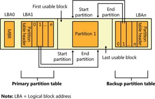
Figure 9-6. Example GPT partition layout
NOTE
Because Windows doesn’t support the creation of multipartition volumes on basic disks, a new basic disk partition is the equivalent of a volume. For this reason, the Disk Management MMC snap-in uses the term partition when you create a volume on a basic disk.
Basic Disk Volume Manager
The volume manager driver (%SystemRoot%\System32\Drivers\Volmgr.sys) creates disk device objects that represent volumes on basic disks and plays an integral role in managing all basic disk volumes, including simple volumes. For each volume, the volume manager creates a device object of the form \Device\HarddiskVolumeX, in which X is a number (starting from 1) that identifies the volume.
The volume manager is actually a bus driver because it’s responsible for enumerating basic disks to detect the presence of basic volumes and report them to the Windows Plug and Play (PnP) manager. To implement this enumeration, the volume manager leverages the PnP manager, with the aid of the partition manager (Partmgr.sys) driver to determine what basic disk partitions exist. The partition manager registers with the PnP manager so that Windows can inform the partition manager whenever the disk class driver creates a partition device object. The partition manager informs the volume manager about new partition objects through a private interface and creates filter device objects that the partition manager then attaches to the partition objects. The existence of the filter objects prompts Windows to inform the partition manager whenever a partition device object is deleted so that the partition manager can update the volume manager. The disk class driver deletes a partition device object when a partition in the Disk Management MMC snap-in is deleted. As the volume manager becomes aware of partitions, it uses the basic disk configuration information to determine the correspondence of partitions to volumes and creates a volume device object when it has been informed of the presence of all the partitions in a volume’s description.
Windows volume drive-letter assignment, a process described shortly, creates drive-letter symbolic links under the \Global?? object manager directory that point to the volume device objects that the volume manager creates. When the system or an application accesses a volume for the first time, Windows performs a mount operation that gives file system drivers the opportunity to recognize and claim ownership for volumes formatted with a file system type they manage. (Mount operations are described in the section Volume Mounting later in this chapter.)
Dynamic Disks
As we’ve stated, dynamic disks are the disk format in Windows necessary for creating multipartition volumes such as mirrors, striped arrays, and RAID-5 arrays (described later in the chapter). Dynamic disks are partitioned using Logical Disk Manager (LDM) partitioning. LDM is part of the Virtual Disk Service (VDS) subsystem in Windows, which consists of user-mode and device driver components and oversees dynamic disks. A major difference between LDM’s partitioning and MBR-style and GPT partitioning is that LDM maintains one unified database that stores partitioning information for all the dynamic disks on a system—including multipartition-volume configuration.
The LDM Database
The LDM database resides in a 1-MB reserved space at the end of each dynamic disk. The need for this space is the reason Windows requires free space at the end of a basic disk before you can convert it to a dynamic disk. The LDM database consists of four regions, which Figure 9-7shows: a header sector that LDM calls the Private Header, a table of contents area, a database records area, and a transactional log area. (The fifth region shown in Figure 9-7 is simply a copy of the Private Header.) The Private Header sector resides 1 MB before the end of a dynamicdisk and anchors the database. As you spend time with Windows, you’ll quickly notice that it uses GUIDs to identify just about everything, and disks are no exception. A GUID (globally unique identifier) is a 128-bit value that various components in Windows use to uniquely identify objects. LDM assigns each dynamic disk a GUID, and the Private Header sector notes the GUID of the dynamic disk on which it resides—hence the Private Header’s designation as information that is private to the disk. The Private Header also stores the name of the disk group, which is the name of the computer concatenated with Dg0 (for example, Daryl-Dg0 if the computer’s name is Daryl), and a pointer to the beginning of the database table of contents. For reliability, LDM keeps a copy of the Private Header in the disk’s last sector.
The database table of contents is 16 sectors in size and contains information regarding the database’s layout. LDM begins the database record area immediately following the table of contents with a sector that serves as the database record header. This sector stores information about the database record area, including the number of records it contains, the name and GUID of the disk group the database relates to, and a sequence number identifier that LDM uses for the next entry it creates in the database. Sectors following the database record header contain 128-byte fixed-size records that store entries that describe the disk group’s partitions and volumes.
A database entry can be one of four types: partition, disk, component, and volume. LDM uses the database entry types to identify three levels that describe volumes. LDM connects entries with internal object identifiers. At the lowest level, partition entries describe soft partitions (hard partitions are described later in this chapter), which are contiguous regions on a disk; identifiers stored in a partition entry link the entry to a component and disk entry. A disk entry represents a dynamic disk that is part of the disk group and includes the disk’s GUID. Acomponent entry serves as a connector between one or more partition entries and the volume entry each partition is associated with. A volume entry stores the GUID of the volume, the volume’s total size and state, and a drive-letter hint. Disk entries that are larger than a database record span multiple records; partition, component, and volume entries rarely span multiple records.
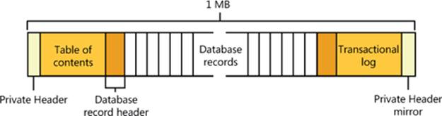
Figure 9-7. LDM database layout
LDM requires three entries to describe a simple volume: a partition, component, and volume entry. The following listing shows the contents of a simple LDM database that defines one 200-MB volume that consists of one partition:
Disk Entry Volume Entry Component Entry Partition Entry
Name: Disk1 Name: Volume1 Name: Volume1-01 Name: Disk1-01
GUID: XXX-XX... ID: 0x408 ID: 0x409 ID: 0x407
Disk ID: 0x404 State: ACTIVE Parent ID: 0x408 Parent ID: 0x409
Size: 200MB Disk ID: 0x404
GUID: XXX-XX... Start: 300MB
Drive Hint: H: Size: 200MB
The partition entry describes the area on a disk that the system assigned to the volume, the component entry connects the partition entry with the volume entry, and the volume entry contains the GUID that Windows uses internally to identify the volume. Multipartition volumes require more than three entries. For example, a striped volume (which is described later in the chapter) consists of at least two partition entries, a component entry, and a volume entry. The only volume type that has more than one component entry is a mirror; mirrors have two component entries, each of which represents one half of the mirror. LDM uses two component entries for mirrors so that when you break a mirror, LDM can split it at the component level, creating two volumes with one component entry each.
The final area of the LDM database is the transactional log area, which consists of a few sectors for storing backup database information as the information is modified. This setup safeguards the database in case of a crash or power failure because LDM can use the log to return the database to a consistent state.
EXPERIMENT: USING LDMDUMP TO VIEW THE LDM DATABASE
You can use LDMDump from Sysinternals to view detailed information about the contents of the LDM database. LDMDump takes a disk number as a command-line argument, and its output is usually more than a few screens in size, so you should pipe its output to a file for viewing in a text editor—for example, ldmdump /d0 > disk.txt. The following example shows excerpts of LDMDump output. The LDM database header displays first, followed by the LDM database records that describe a 12-GB disk with three 4-GB dynamic volumes. The volume’s database entry is listed as Volume1. At the end of the output, LDMDump lists the soft partitions and definitions of volumes it locates in the database.
C:\>ldmdump /d0
Logical Disk Manager Configuration Dump v1.03
Copyright (C) 2000-2002 Mark Russinovich
PRIVATE HEAD:
Signature : PRIVHEAD
Version : 2.12
Disk Id : b5f4a801-758d-11dd-b7f0-000c297f0108
Host Id : 1b77da20-c717-11d0-a5be-00a0c91db73c
Disk Group Id : b5f4a7fd-758d-11dd-b7f0-000c297f0108
Disk Group Name : WIN-SL5V78KD01W-Dg0
Logical disk start : 3F
Logical disk size : 7FF7C1 (4094 MB)
Configuration start: 7FF800
Configuration size : 800 (1 MB)
Number of TOCs : 2
TOC size : 7FD (1022 KB)
Number of Configs : 1
Config size : 5C9 (740 KB)
Number of Logs : 1
Log size : E0 (112 KB)
TOC 1:
Signature : TOCBLOCK
Sequence : 0x1
Config bitmap start: 0x11
Config bitmap size : 0x5C9
Log bitmap start : 0x5DA
Log bitmap size : 0xE0
...
VBLK DATABASE:
0x000004: [000001] <DiskGroup>
Name : WIN-SL5V78KD01W-Dg0
Object Id : 0x0001
GUID : b5f4a7fd-758d-11dd-b7f0-000c297f010
0x000006: [000003] <Disk>
Name : Disk1
Object Id : 0x0002
Disk Id : b5f4a7fe-758d-11dd-b7f0-000c297f010
0x000007: [000005] <Disk>
Name : Disk2
Object Id : 0x0003
Disk Id : b5f4a801-758d-11dd-b7f0-000c297f010
0x000008: [000007] <Disk>
Name : Disk3
Object Id : 0x0004
Disk Id : b5f4a804-758d-11dd-b7f0-000c297f010
0x000009: [000009] <Component>
Name : Volume1-01
Object Id : 0x0006
Parent Id : 0x0005
0x00000A: [00000A] <Partition>
Name : Disk1-01
Object Id : 0x0007
Parent Id : 0x3157
Disk Id : 0x0000
Start : 0x7C100
Size : 0x0 (0 MB)
Volume Off : 0x3 (0 MB)
0x00000B: [00000B] <Partition>
Name : Disk2-01
Object Id : 0x0008
Parent Id : 0x3157
Disk Id : 0x0000
Start : 0x7C100
Size : 0x0 (0 MB)
Volume Off : 0x7FE80003 (1047808 MB)
0x00000C: [00000C] <Partition>
Name : Disk3-01
Object Id : 0x0009
Parent Id : 0x3157
Disk Id : 0x0000
Start : 0x7C100
Size : 0x0 (0 MB)
Volume Off : 0xFFD00003 (2095616 MB)
0x00000D: [00000F] <Volume>
Name : Volume1
Object Id : 0x0005
Volume state: ACTIVE
Size : 0x017FB800 (12279 MB)
GUID : b5f4a806-758d-11dd-b7f0-c297f0108
Drive Hint : E:
LDM and GPT or MBR-Style Partitioning
When you install Windows on a computer, one of the first things it requires you to do is to create a partition on the system’s primary physical disk (specified in the BIOS or UEFI as the disk from which to boot the system). To make enabling BitLocker easier, Windows Setup will create a small (100 MB) unencrypted partition known as the system volume, containing the Boot Manager (Bootmgr), Boot Configuration Database (BCD), and other early boot files. (By default, this volume does not have a drive letter assigned to it, but you can assign one using the Disk Management MMC snap-in, at %SystemRoot%\System32\Diskmgmt.msc, if you want to examine the contents of the volume with Windows Explorer). In addition, Windows Setup requires you to create a partition that serves as the home for the boot volume, onto which the setup program installs the Windows system files and creates the system directory (\Windows). The nomenclature that Microsoft defines for system and boot volumes is somewhat confusing. The system volume is where Windows places boot files, such as the Boot Manager, and the boot volume is where Windows stores the rest of the operating system files, such as Ntoskrnl.exe, the core kernel file.
NOTE
If the system has BitLocker enabled, the boot volume will be encrypted, but the system volume is never encrypted.
Although the partitioning data of a dynamic disk resides in the LDM database, LDM implements MBR-style partitioning or GPT partitioning so that the Windows boot code can find the system and boot volumes when the volumes are on dynamic disks. (Winload and the Itanium firmware, for example, know nothing about LDM partitioning.) If a disk contains the system or boot volumes, partitions in the MBR or GPT describe the location of those volumes. Otherwise, one partition encompasses the entire usable area of the disk. LDM marks this partition as type “LDM”. The region encompassed by this place-holding MBR-style or GPT partition is where LDM creates partitions that the LDM database organizes. On MBR-partitioned disks the LDM database resides in hidden sectors at the end of the disk, and on GPT-partitioned disks there exists an LDM metadata partition that contains the LDM database near the beginning of the disk.
Another reason LDM creates an MBR or a GPT is so that legacy disk-management utilities, including those that run under Windows and under other operating systems in dual-boot environments, don’t mistakenly believe a dynamic disk is unpartitioned.
Because LDM partitions aren’t described in the MBR or GPT of a disk, they are called soft partitions; MBR-style and GPT partitions are called hard partitions. Figure 9-8 illustrates this dynamic disk layout on an MBR-style partitioned disk.
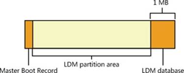
Figure 9-8. Internal dynamic disk organization
Dynamic Disk Volume Manager
The Disk Management MMC snap-in DLL (DMDiskManager, located in %SystemRoot%\System32\Dmdskmgr.dll), shown in Figure 9-9, is used to create and change the contents of the LDM database. When you launch the Disk Management MMC snap-in, DMDiskManager loads into memory and reads the LDM database from each disk and returns the information it obtains to the user. If it detects a database from another computer’s disk group, it notes that the volumes on the disk are foreign and lets you import them into the current computer’s database if you want to use them. As you change the configuration of dynamic disks, DMDiskManager updates its in-memory copy of the database. When DMDiskManager commits changes, it passes the updated database to the VolMgrX driver (%SystemRoot%\System32\Drivers\Volmgrx.sys). VolMgrX is a kernel-mode DLL that provides dynamic disk functionality for VolMgr, so it controls access to the on-disk database and creates device objects that represent the volumes on dynamic disks. When you exit Disk Management, DMDiskManager stops.
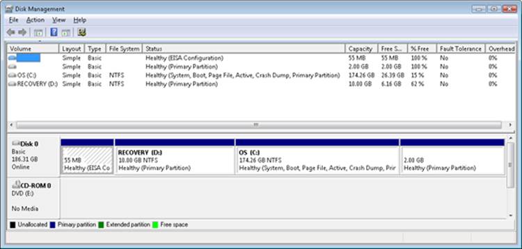
Figure 9-9. Disk Management MMC snap-in
Multipartition Volume Management
VolMgr is responsible for presenting volumes that file system drivers manage and for mapping I/O directed at volumes to the underlying partitions that they’re part of. For simple volumes, this process is straightforward: the volume manager ensures that volume-relative offsets are translated to disk-relative offsets by adding the volume-relative offset to the volume’s starting disk offset.
Multipartition volumes are more complex because the partitions that make up a volume can be located on discontiguous partitions or even on different disks. Some types of multipartition volumes use data redundancy, so they require more involved volume-to-disk–offset translation. Thus, VolMgr uses VolMgrX to process all I/O requests aimed at the multipartition volumes they manage by determining which partitions the I/O ultimately affects.
The following types of multipartition volumes are available in Windows:
§ Spanned volumes
§ Mirrored volumes
§ Striped volumes
§ RAID-5 volumes
After describing multipartition-volume partition configuration and logical operation for each of the multipartition-volume types, we’ll cover the way that the VolMgr driver handles IRPs that a file system driver sends to multipartition volumes. The term volume manager is used to represent VolMgr and the VolMgrX extension DLL throughout the explanation of multipartition volumes.
Spanned Volumes
A spanned volume is a single logical volume composed of a maximum of 32 free partitions on one or more disks. The Disk Management MMC snap-in combines the partitions into a spanned volume, which can then be formatted for any of the Windows-supported file systems.Figure 9-10 shows a 100-GB spanned volume identified by drive letter D that has been created from the last third of the first disk and the first third of the second. Spanned volumes were called volume sets in Windows NT 4.
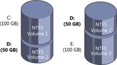
Figure 9-10. Spanned volume
A spanned volume is useful for consolidating small areas of free disk space into one larger volume or for creating a single large volume out of two or more small disks. If the spanned volume has been formatted for NTFS, it can be extended to include additional free areas or additional disks without affecting the data already stored on the volume. This extensibility is one of the biggest benefits of describing all data on an NTFS volume as a file. NTFS can dynamically increase the size of a logical volume because the bitmap that records the allocation status of the volume is just another file—the bitmap file. The bitmap file can be extended to include any space added to the volume. Dynamically extending a FAT volume, on the other hand, would require the FAT itself to be extended, which would dislocate everything else on the disk.
A volume manager hides the physical configuration of disks from the file systems installed on Windows. NTFS, for example, views volume D: in Figure 9-10 as an ordinary 100-GB volume. NTFS consults its bitmap to determine what space in the volume is free for allocation. Aftertranslating a byte offset to a cluster offset, it then calls the volume manager to read or write data beginning at a particular cluster offset on the volume. The volume manager views the physical sectors in the spanned volume as numbered sequentially from the first free area on the first disk to the last free area on the last disk. It determines which physical sector on which disk corresponds to the supplied cluster offset.
Striped Volumes
A striped volume is a series of up to 32 partitions, one partition per disk, that gets combined into a single logical volume. Striped volumes are also known as RAID level 0 (RAID-0) volumes. Figure 9-11 shows a striped volume consisting of three partitions, one on each of three disks. (A partition in a striped volume need not span an entire disk; the only restriction is that the partitions on each disk be the same size.)
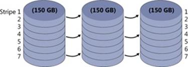
Figure 9-11. Striped volume
To a file system, this striped volume appears to be a single 450-GB volume, but the volume manager optimizes data storage and retrieval times on the striped volume by distributing the volume’s data among the physical disks. The volume manager accesses the physical sectors of the disks as if they were numbered sequentially in stripes across the disks, as illustrated in Figure 9-12.

Figure 9-12. Logical numbering of physical sectors on a striped volume
Because each stripe unit is a relatively narrow 64 KB (a value chosen to prevent small individual reads and writes from accessing two disks), the data tends to be distributed evenly among the disks. Striping thus increases the probability that multiple pending read and write operations will be bound for different disks. And because data on all three disks can be accessed simultaneously, latency time for disk I/O is often reduced, particularly on heavily loaded systems.
Spanned volumes make managing disk volumes more convenient, and striped volumes spread the I/O load over multiple disks. These two volume-management features don’t provide the ability to recover data if a disk fails, however. For data recovery, the volume manager implements two redundant storage schemes: mirrored volumes and RAID-5 volumes. These features are created with the Windows Disk Management administrative tool.
Mirrored Volumes
In a mirrored volume, the contents of a partition on one disk are duplicated in an equal-sized partition on another disk. Mirrored volumes are sometimes referred to as RAID level 1 (RAID-1). A mirrored volume is shown in Figure 9-13.
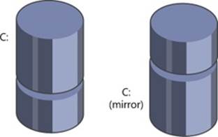
Figure 9-13. Mirrored volume
When a program writes to drive C:, the volume manager writes the same data to the same location on the mirror partition. If the first disk or any of the data on its C: partition becomes unreadable because of a hardware or software failure, the volume manager automatically accesses the data from the mirror partition. A mirror volume can be formatted for any of the Windows-supported file systems. The file system drivers remain independent and are not affected by the volume manager’s mirroring activity.
Mirrored volumes can aid in read I/O throughput on heavily loaded systems. When I/O activity is high, the volume manager balances its read operations between the primary partition and the mirror partition (accounting for the number of unfinished I/O requests pending from each disk). Two read operations can proceed simultaneously and thus theoretically finish in half the time. When a file is modified, both partitions of the mirror set must be written, but disk writes are performed in parallel, so the performance of user-mode programs is generally not affected by the extra disk update.
Mirrored volumes are the only multipartition volume type supported for system and boot volumes. The reason for this is that the Windows boot code, including the MBR code and Winload, don’t have the sophistication required to understand multipartition volumes—mirrored volumes are the exception because the boot code treats them as simple volumes, reading from the half of the mirror marked as the boot or system drive in the MBR-style partition table. Because the boot code doesn’t modify the disk metadata and will read or write to the same half of the mirrored set, it can safely ignore the other half of the mirror; however, the Boot Manager and OS loader will update the file \Boot\BootStat.dat on the system volume. This file is used only to communicate status between the various phases of booting, so, again, it does not need to be written to the other half of the mirror.
EXPERIMENT: WATCHING MIRRORED VOLUME I/O OPERATIONS
Using the Performance Monitor, you can verify that write operations directed at mirrored volumes copy to both disks that make up the mirror and that read operations, if relatively infrequent, occur primarily from one half of the volume. This experiment requires three hard disks. If you don’t have three disks, you can skip the experiment setup instructions and view the Performance tool screen shot in this experiment that demonstrates the experiment’s results.
Use the Disk Management MMC snap-in to create a mirrored volume. To do this, perform the following steps:
1. Run Disk Management by starting Computer Management, expanding the Storage tree, and clicking Disk Management (or by inserting Disk Management as a snap-in in an MMC console).
2. Right-click on an unallocated space of a drive, and then click New Simple Volume.
3. Follow the instructions in the New Simple Volume Wizard to create a simple volume. (Make sure there’s enough room on another disk for a volume of the same size as the one you’re creating.)
4. Right-click on the new volume, and then click Add Mirror on the context menu.
Once you have a mirrored volume, run the Performance Monitor tool and add counters for the PhysicalDisk performance object for both disk instances that contain a partition belonging to the mirror. Select the Disk Writes/sec counters for each instance. Select a large directory from the third disk (the one that isn’t part of the mirrored volume), and copy it to the mirrored volume. The Performance Monitor tool output window should look something like the following screen shot as the copy operation progresses.
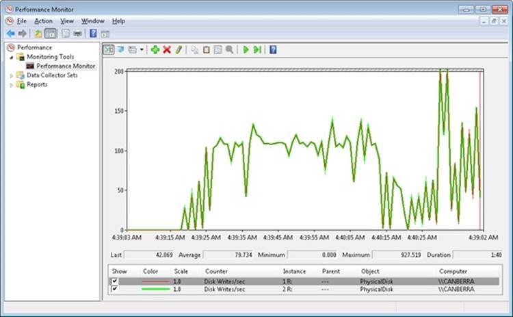
The top two lines, which overlap throughout the timeline, are the Disk Writes/sec counters for each disk. The screen shot reveals that the volume manager (in this case VolMgr) is writing the copied file data to both halves of the volume.
RAID-5 Volumes
A RAID-5 volume is a fault tolerant variant of a regular striped volume. RAID-5 volumes implement RAID level 5. They are also known as striped volumes with rotated parity because they are based on the striping approach taken by striped volumes. Fault tolerance is achieved by reserving the equivalent of one disk for storing parity for each stripe. Figure 9-14 is a visual representation of a RAID-5 volume.
In Figure 9-14, the parity for stripe 1 is stored on disk 1. It contains a byte-for-byte logical sum (XOR) of the first stripe units on disks 2 and 3. The parity for stripe 2 is stored on disk 2, and the parity for stripe 3 is stored on disk 3. Rotating the parity across the disks in this way is an I/O optimization technique. Each time data is written to a disk, the parity bytes corresponding to the modified bytes must be recalculated and rewritten. If the parity were always written to the same disk, that disk would be busy continually and could become an I/O bottleneck.
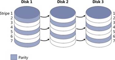
Figure 9-14. RAID-5 volume
Recovering a failed disk in a RAID-5 volume relies on a simple arithmetic principle: in an equation with n variables, if you know the value of n – 1 of the variables, you can determine the value of the missing variable by subtraction. For example, in the equation x + y = z, where zrepresents the parity stripe unit, the volume manager computes z – y to determine the contents of x; to find y, it computes z – x. The volume manager uses similar logic to recover lost data. If a disk in a RAID-5 volume fails or if data on one disk becomes unreadable, the volume manager reconstructs the missing data by using the XOR operation (bitwise logical addition).
If disk 1 in Figure 9-14 fails, the contents of its stripe units 2 and 5 are calculated by XOR-ing the corresponding stripe units of disk 3 with the parity stripe units on disk 2. The contents of stripes 3 and 6 on disk 1 are similarly determined by XOR-ing the corresponding stripe units of disk 2 with the parity stripe units on disk 3. At least three disks (or, rather, three same-sized partitions on three disks) are required to create a RAID-5 volume.
The Volume Namespace
The volume namespace mechanism handles the assignment of drive letters to device objects that represent actual volumes, which lets Windows applications access these drives through familiar means, and also provides mount and dismount functionality.
The Mount Manager
The Mount Manager device driver (%SystemRoot%\System32\Drivers\Mountmgr.sys) assigns drive letters for dynamic disk volumes and basic disk volumes created after Windows is installed, CD-ROMs, floppies, and removable devices. Windows stores all drive-letter assignments under HKLM\SYSTEM\MountedDevices. If you look in the registry under that key, you’ll see values with names such as \??\Volume{X} (where X is a GUID) and values such as \DosDevices\C:. Every volume has a volume name entry, but a volume doesn’t necessarily have an assigned drive letter (for example, the system volume). Figure 9-15 shows the contents of an example Mount Manager registry key. Note that the MountedDevices key isn’t included in a control set and so isn’t protected by the last known good boot option. (See the section Last Known Good in Chapter 13 for more information on control sets and the last known good boot option.)
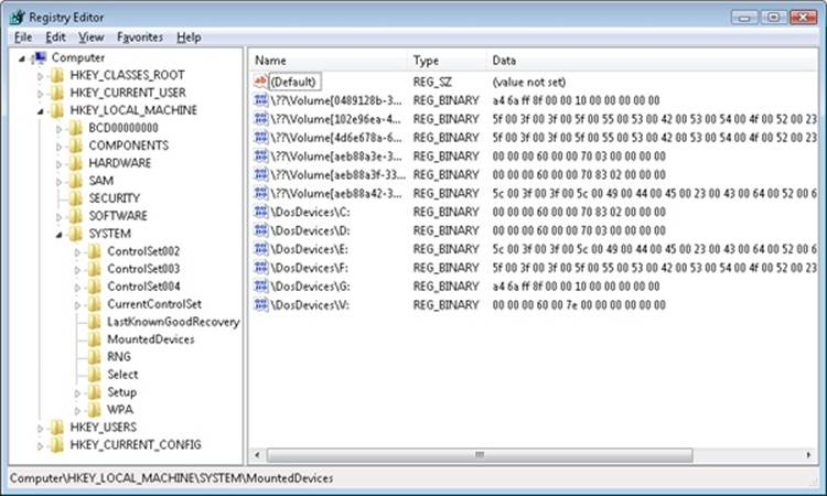
Figure 9-15. Mounted devices listed in the Mount Manager’s registry key
The data that the registry stores in values for basic disk volume drive letters and volume names is the disk signature and the starting offset of the first partition associated with the volume. The data that the registry stores in values for dynamic disk volumes includes the volume’sVolMgr-internal GUID. When the Mount Manager initializes during the boot process, it registers with the Windows Plug and Play subsystem so that it receives notification whenever a device identifies itself as a volume. When the Mount Manager receives such a notification, it determines the new volume’s GUID or disk signature and uses the GUID or signature as a guide to look in its internal database, which reflects the contents of the MountedDevices registry key. The Mount Manager then determines whether its internal database contains the drive-letter assignment. If the volume has no entry in the database, the Mount Manager asks VolMgr for a suggested drive-letter assignment and stores that in the database. VolMgr doesn’t return suggestions for simple volumes, but it looks at the drive-letter hint in the volume’s database entry for dynamic volumes.
If no suggested drive-letter assignment exists for a dynamic volume, the Mount Manager uses the first unassigned drive letter (if one exists), defines a new assignment, creates a symbolic link for the assignment (for example, \Global??\D:), and updates the MountedDevices registry key. If there are no available drive letters, no drive-letter assignment is made. At the same time, the Mount Manager creates a volume symbolic link (that is, \Global??\Volume{X}) that defines a new volume GUID if the volume doesn’t already have one. This GUID is different from the volume GUIDs that VolMgr uses internally.
Mount Points
Mount points let you link volumes through directories on NTFS volumes, which makes volumes with no drive-letter assignment accessible. For example, an NTFS directory that you’ve named C:\Projects could mount another volume (NTFS or FAT) that contains your project directories and files. If your project volume had a file you named \CurrentProject\Description.txt, you could access the file through the path C:\Projects\CurrentProject\Description.txt. What makes mount points possible is reparse point technology. (Reparse points are discussed in more detail in Chapter 12.)
A reparse point is a block of arbitrary data with some fixed header data that Windows associates with an NTFS file or directory. An application or the system defines the format and behavior of a reparse point, including the value of the unique reparse point tag that identifies reparse points belonging to the application or system and specifies the size and meaning of the data portion of a reparse point. (The data portion can be as large as 16 KB.) Any application that implements a reparse point must supply a file system filter driver to watch for reparse-related return codes for file operations that execute on NTFS volumes, and the driver must take appropriate action when it detects the codes. NTFS returns a reparse status code whenever it processes a file operation and encounters a file or directory with an associated reparse point.
The Windows NTFS file system driver, the I/O manager, and the object manager all partly implement reparse point functionality. The object manager initiates pathname parsing operations by using the I/O manager to interface with file system drivers. Therefore, the object manager must retry operations for which the I/O manager returns a reparse status code. The I/O manager implements pathname modification that mount points and other reparse points might require, and the NTFS file system driver must associate and identify reparse point data with files and directories. You can therefore think of the I/O manager as the reparse point file system filter driver for many Microsoft-defined reparse points.
One common use of reparse points is the symbolic link functionality offered on Windows by NTFS (see Chapter 12 for more information on NTFS symbolic links). If the I/O manager receives a reparse status code from NTFS and the file or directory for which NTFS returned the code isn’t associated with one of a handful of built-in Windows reparse points, no filter driver claimed the reparse point. The I/O manager then returns an error to the object manager that propagates as a “file cannot be accessed by the system” error to the application making the file or directory access.
Mount points are reparse points that store a volume name (\Global??\Volume{X}) as the reparse data. When you use the Disk Management MMC snap-in to assign or remove path assignments for volumes, you’re creating mount points. You can also create and display mount points by using the built-in command-line tool Mountvol.exe (%SystemRoot%\System32\Mountvol.exe).
The Mount Manager maintains the Mount Manager remote database on every NTFS volume in which the Mount Manager records any mount points defined for that volume. The database file resides in the directory System Volume Information on the NTFS volume. Mount points move when a disk moves from one system to another and in dual-boot environments—that is, when booting between multiple Windows installations—because of the existence of the Mount Manager remote database. NTFS also keeps track of reparse points in the NTFS metadata file \$Extend\$Reparse. (NTFS doesn’t make any of its metadata files available for viewing by applications.) NTFS stores reparse point information in the metadata file so that Windows can, for example, easily enumerate the mount points (which are reparse points) defined for a volume when a Windows application, such as Disk Management, requests mount-point definitions.
Volume Mounting
Because Windows assigns a drive letter to a volume doesn’t mean that the volume contains data that has been organized in a file system format that Windows recognizes. The volume-recognition process consists of a file system claiming ownership for a partition; the process takes place the first time the kernel, a device driver, or an application accesses a file or directory on a volume. After a file system driver signals its responsibility for a partition, the I/O manager directs all IRPs aimed at the volume to the owning driver. Mount operations in Windows consist of three components: file system driver registration, volume parameter blocks (VPBs), and mount requests.
NOTE
The partition manager honors the system SAN policy, which can be set with the Windows DiskPart utility, that specifies whether it should surface disks for visibility to the volume manager. The default policy in Windows Server 2008 Enterprise and Datacenter editions is to not make SAN disks visible, which prevents the system from aggressively mounting their volumes.
The I/O manager oversees the mount process and is aware of available file system drivers because all file system drivers register with the I/O manager when they initialize. The I/O manager provides the IoRegisterFileSystem function to local disk (rather than network) file system drivers for this registration. When a file system driver registers, the I/O manager stores a reference to the driver in a list that the I/O manager uses during mount operations.
Every device object contains a VPB data structure, but the I/O manager treats VPBs as meaningful only for volume device objects. A VPB serves as the link between a volume device object and the device object that a file system driver creates to represent a mounted file system instance for that volume. If a VPB’s file system reference is empty (VPB->DeviceObject == NULL), no file system has mounted the volume. The I/O manager checks a volume device object’s VPB whenever an open API that specifies a file name or a directory name on a volume device object executes.
For example, if the Mount Manager assigns drive letter D to the second volume on a system, it creates a \Global??\D: symbolic link that resolves to the device object \Device\HarddiskVolume2. A Windows application that attempts to open the \Temp\Test.txt file on the D: drive specifies the name D:\Temp\Test.txt, which the Windows subsystem converts to \Global??\D:\Temp\Test.txt before invoking NtCreateFile, the kernel’s file-open routine. NtCreateFile uses the object manager to parse the name, and the object manager encounters the \Device\HarddiskVolume2 device object with the path \Temp\Test.txt still unresolved. At that point, the I/O manager checks to see whether \Device\HarddiskVolume2’s VPB references a file system. If it doesn’t, the I/O manager asks each registered file system driver via a mount request whether the driver recognizes the format of the volume in question as the driver’s own.
EXPERIMENT: LOOKING AT VPBS
You can look at the contents of a VPB by using the !vpb kernel debugger command. Because the VPB is pointed to by the device object for a volume, you must first locate a volume device object. To do this, you must dump the volume manager’s driver object, locate a device object that represents a volume, and display the device object, which reveals its Vpb field.
lkd> !drvobj volmgr
Driver object (84905030) is for:
\Driver\volmgr
Driver Extension List: (id , addr)
Device Object list:
84a64780 849d5b28 84a64518 84a64030
84905e00
The !drvobj command lists the addresses of the device objects a driver owns. In this example, there are five device objects. One of them represents the programmatic (control) interface to the device driver, and the rest are volume device objects. Because the objects are listed in reverse order from the way that they were created and the driver creates the control device object first, the first device object listed is that of a volume. Now execute the !devobj kernel debugger command on the volume device object address:
lkd> !devobj 84a64780
Device object (84a64780) is for:
HarddiskVolume4 \Driver\volmgr DriverObject 84905030
Current Irp 00000000 RefCount 0 Type 00000007 Flags 00001050
Vpb 84a64228 Dacl 8b1a8674 DevExt 84a64838 DevObjExt 84a64930 Dope 849fd838 DevNode
849d5938
ExtensionFlags (0x00000800)
Unknown flags 0x00000800
AttachedDevice (Upper) 84a66020 \Driver\volsnap
Device queue is not busy
The !devobj command shows the Vpb field for the volume device object. (The device object shown is named HarddiskVolume4.) Now you’re ready to execute the !vpb command:
lkd> !vpb 84a64228
Vpb at 0x84a64228
Flags: 0x1 mounted
DeviceObject: 0x84a6b020
RealDevice: 0x849d5b28
RefCount: 4311
Volume Label: OS
The command reveals that the volume device object is mounted by a file system driver that has assigned the volume the name OS. The RealDevice field in the VPB points back to the volume device object, and the DeviceObject field points to the mounted file system device object. You can use !devobj on this address to get more information on the mounted file system, as seen in the following output, which shows that NTFS has mounted the volume:
lkd> !devobj 0x84a6b020
Device object (84a6b020) is for:
\FileSystem\Ntfs DriverObject 84a02ad0
Current Irp 00000000 RefCount 0 Type 00000008 Flags 00040000
DevExt 84a6b0d8 DevObjExt 84a6bc00
ExtensionFlags (0x00000800)
Unknown flags 0x00000800
AttachedDevice (Upper) 84a63ac0 \FileSystem\FltMgr
Device queue is not busy
The convention followed by file system drivers for recognizing volumes mounted with their format is to examine the volume’s boot record (VBR), which is stored in the first sector of the volume. Boot records for Microsoft file systems contain a field that stores a file system format type. File system drivers usually examine this field, and if it indicates a format they manage, they look at other information stored in the boot record. This information usually includes a file system name field and enough data for the file system driver to locate critical metadata files on the volume. NTFS, for example, will recognize a volume only if the MBR partition Type field is NTFS (0x07), the Name field is “NTFS,” and the critical metadata files described by the boot record are consistent.
If a file system driver signals affirmatively, the I/O manager fills in the VPB and passes the open request with the remaining path (that is, \Temp\Test.txt) to the file system driver. The file system driver completes the request by using its file system format to interpret the data that the volume stores. After a mount fills in a volume device object’s VPB, the I/O manager hands subsequent open requests aimed at the volume to the mounted file system driver. If no file system driver claims a volume, Raw—a file system driver built into Ntoskrnl.exe—claims the volume and fails all requests to open files on that partition; however, Raw does allow sector I/O to the partition for applications with administrator privileges, but even an administrator cannot write to sectors of a mounted volume, except for the boot sectors. Figure 9-16 shows a simplified example (that is, the figure omits the file system driver’s interactions with the Windows cache and memory managers) of the path that I/O directed at a mounted volume follows.
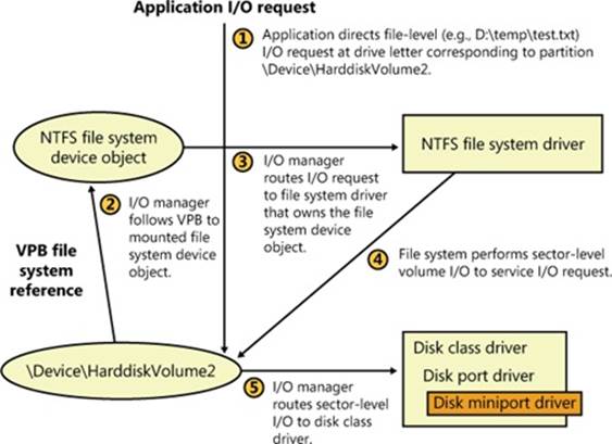
Figure 9-16. Mounted volume I/O flow
Instead of having every file system driver loaded, regardless of whether they have any volumes to manage, Windows tries to minimize memory usage by using a surrogate driver named File System Recognizer (%SystemRoot%\System32\Drivers\Fs_rec.sys) to perform preliminary file system recognition. File System Recognizer knows enough about each file system format that Windows supports to be able to examine a boot record and determine whether it’s associated with a Windows file system driver. When the system boots, File System Recognizer registers as a file system driver, and when the I/O manager calls it during a file system mount operation for a new volume, File System Recognizer loads the appropriate file system driver if the VBR describes a file system that isn’t loaded. After loading a file system driver, File System Recognizer forwards the mount IRP to the file system driver and lets it claim ownership of the volume.
Aside from the boot volume, which a driver mounts while the kernel is initializing, file system drivers mount most volumes when the Chkdsk file system consistency-checking application runs during a boot sequence. The boot-time version of Chkdsk is a native application (as opposed to a Win32 application) named Autochk.exe (%SystemRoot%\System32\Autochk.exe), and the Session Manager (%SystemRoot%\System32\Smss.exe) runs it because it is specified as a boot-run program in the HKLM\SYSTEM\CurrentControlSet\Control\Session Manager\BootExecute value. Autochk accesses each drive letter to see whether the volume associated with the letter requires a consistency check.
One place in which mounting can occur more than once for the same disk is with removable media. Windows file system drivers respond to media changes by querying the disk’s volume identifier. If they see the volume identifier change, the driver dismounts the disk and attempts to remount it.
Volume I/O Operations
File system drivers manage data stored on volumes but rely on the volume manager to interact with storage drivers to transfer data to and from the disk or disks on which a volume resides. File system drivers obtain references to the volume manager’s volume objects through the mount process and then send the volume manager requests via the volume objects. Applications can also send the volume manager requests, bypassing file system drivers, when they want to directly manipulate a volume’s data. File-undelete programs are an example of applications that do this.
Whenever a file system driver or an application sends an I/O request to a device object that represents a volume, the Windows I/O manager routes the request (which comes in an IRP—a self-contained package, described in Chapter 8) to the volume manager that created the target device object. Thus, if an application (running with administrator privileges) wants to read the boot sector of the second volume on the system (which is a simple volume in this example), it opens a handle to \\.\HarddiskVolume2 and then calls ReadFile to read 512 bytes starting at offset zero on the device. (Both the starting byte offset and length must be a multiple of the sector size.) The I/O manager sends the application’s request in the form of an IRP to the volume manager that owns the device object, notifying it that the IRP is directed at the HarddiskVolume2 device.
Because volumes are logical conveniences that Windows uses to represent contiguous areas on one or more physical disks, the volume manager must translate offsets that are relative to a volume to offsets that are relative to the beginning of a disk. If volume 2 consists of one partition that begins 4,096 sectors into the disk, the partition manager would adjust the IRP’s parameters to designate an offset with that value before passing the request to the disk class driver. The disk class driver uses a miniport driver to carry out physical disk I/O, and reads the requested data into an application buffer designated in the IRP.
Some examples of a volume manager’s operations will help clarify its role when it handles requests aimed at multipartition volumes. If a striped volume consists of two partitions, partition 1 and partition 2, the VolMgr device object intercepts file system disk I/O aimed at the device object for the volume, and the VolMgr driver adjusts the request before passing it to the disk class driver. The adjustment that VolMgr makes configures the request to refer to the correct offset of the request’s target stripe on either partition 1 or partition 2. If the I/O spans both partitions of the volume, VolMgr must issue two associated I/O requests, one aimed at each disk. This is shown in Figure 9-17.
In the case of writes to a mirrored volume, VolMgr splits each request so that each half of the mirror receives the write operation. For mirrored reads, VolMgr performs a read from half of a mirror, relying on the other half when a read operation fails.
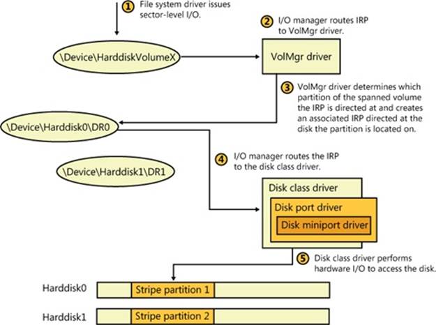
Figure 9-17. VolMgr I/O operations
Virtual Disk Service
A company that makes storage products such as RAID adapters, hard disks, or storage arrays has to implement custom applications for installing and managing their devices. The use of different management applications for different storage devices has obvious drawbacks from the perspective of system administration. These drawbacks include learning multiple interfaces and the inability to use standard Windows storage management tools to manage third-party storage devices.
Windows includes the Virtual Disk Service (or VDS, located at %SystemRoot%\System32\Vds.exe), which provides a unified high-level storage interface so that administrators can manage storage devices from different vendors using the same user interfaces. VDS is shown inFigure 9-18. VDS exports a COM-based API that allows applications to create and format disks and to view and manage hardware RAID adapters. For example, a utility can use the VDS API to query the list of physical disks that map to a RAID logical unit number (LUN). Windows disk-management utilities, including the Disk Management MMC snap-in and the DiskPart and DiskRAID command-line tools, use VDS APIs.
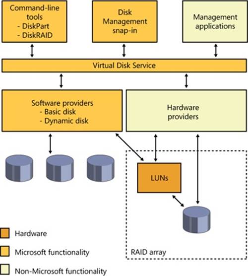
Figure 9-18. VDS service architecture
VDS supplies two interfaces, one for software providers and one for hardware providers:
§ Software providers implement interfaces to high-level storage abstractions such as disks, disk partitions, and volumes. Examples of operations supported by these interfaces include creating, extending, and deleting volumes; adding or breaking mirrors; and formatting and assigning drive letters. VDS looks for registered software providers in HKLM\SYSTEM\CurrentControlSet\Services\Vds\SoftwareProviders, which contains subkeys whose names are GUIDs. Within each subkey is a value named ClsId, which specifies the COM class ID, and these are listed in HKEY_CLASSES_ROOT\CLSID\<ClsId>. Windows includes the VDS Dynamic Provider (%SystemRoot%\System32\Vdsdyn.dll) for interfacing to dynamic disks and the VDS Basic Provider (%SystemRoot%\System32\Vdsbas.dll) for interfacing to basic disks.
§ Hardware vendors implement VDS hardware providers as DLLs that register under HKLM\SYSTEM\CurrentControlSet\Services\Vds\HardwareProviders and that translate device-independent VDS commands into commands for their hardware. The hardware provider allows formanagement of a storage subsystem such as a hardware RAID array or an adapter card, and supported operations include creating, extending, deleting, masking, and unmasking LUNs.
When an application initiates a connection to the VDS API and the VDS service isn’t started, the Svchost process hosting the RPC service starts the VDS loader process (%SystemRoot%\System32\Vdsldr.exe), which starts the VDS service process and then exits. When the last connection to the VDS API closes, the VDS service process exits.
Virtual Hard Disk Support
Windows includes extensive built-in support for VHD (Virtual Hard Disk, the Microsoft virtual machine disk format) files. Using disk-management utilities, you can create, delete, and merge VHDs, as well as attach them to the system as though they were physical disks. Windows also includes support for booting Windows installations stored in NTFS volumes within VHDs.
There are three types of VHDs, all of which are supported by the VHD functionality in Windows:
§ Dynamic The VHD does not necessarily contain all the blocks it is advertising (thinly provisioned) and will be grown as necessary, up to its maximum size. In other words, the amount of space being consumed by the VHD is equal to the amount of data that is being stored in it (plus a small amount of overhead for the VHD container).
§ Fixed The VHD is of fixed size, cannot grow, and contains all the disk blocks it is advertising (fully provisioned).
§ Differencing Similar to a dynamic VHD, but contains only the sectors that would have been modified when compared with a parent VHD (which is read-only). The parent VHD may be of any of the three VHD types (including another differencing VHD). Differencing VHDs are generally used for taking a snapshot of the state of a parent VHD. That state can then be recovered by simply deleting the differencing VHD. This is often used in checkpointing virtual machines (VMs) to enable the user to return the VM to a particular state. Note that the differencing VHD must be kept in the same directory as the parent VHD.
When presented to the system, the standard partition manager and volume manager mounting volume recognition and mounting processes take place, making file systems stored in the VHD accessible using Windows file system APIs and utilities.
VHDs can be contained within a VHD, so Windows limits the number of nesting levels of VHDs that it will present to the system as a disk to two, with the maximum number of nesting levels specified by the registry value HKLM\System\CurrentControlSet\Services\FsDepends\Parameters\VirtualDiskMaxTreeDepth. Mounting VHDs can be prevented by setting the registry value HKLM\System\CurrentControlSet\Services\FsDepends\Parameters\VirtualDiskNoLocalMount to 1.
Windows can also boot from a VHD. A bootable VHD may be created from scratch during installation (when booting the Windows installation disk) or from a running system using various tools, including ImageX or Sysinternals’s Disk2VHD. That “system in a VHD” can be run under Virtual PC or Hyper-V (on Windows Server), and Windows Ultimate and Enterprise editions can directly boot from a VHD.
Windows also extends its support of VHDs to all its built-in disk-management utilities. Creating, mounting, and dismounting a VHD can be done while Windows is running using the Disk Management MMC snap-in (%SystemRoot%\System32\Diskmgmt.msc) or the DiskPart (%SystemRoot%\System32\Diskpart.exe) command-line tool. These tools are implemented using Virtual Disk Service (VDS) APIs, which can also be used by third-party utilities for managing and manipulating VHDs.
Attaching VHDs
The root-enumerated bus driver Vdrvroot (%SystemRoot%\System32\Drivers\Vdrvroot.sys) creates a physical device object (PDO) for each nested file system to be mounted. The PnP manager loads the Vhdmp (%SystemRoot%\System32\Drivers\Vhdmp.sys) Storport miniport driver as the function driver on the PDO, exposing what to the rest of the system looks like a physical disk. The I/O manager then layers the rest of the storage stack (disk class driver, partition manager, volume manager, and file system driver) on top of the device stack (DevStack) containing Vhdmp. When Vhdmp receives sector read and write requests, it translates those requests into offsets within the VHD file and then forwards the requests to the storage stack where the VHD file is located.
Nested File Systems
To support nested file systems, a dependency tree is created to track which file systems have dependencies on other file systems. This is important for several systemwide operations to function properly, such as dismounting a volume (dependent file systems would have to be dismounted first), system shutdown (similar to volume dismounting), and volume snapshots (dependent volumes need to be flushed before the parent during a FlushAndHold operation). Dependencies are tracked by a file system minifilter driver (%SystemRoot%\System32\Drivers\Fsdepends.sys), which sits above the file system driver. Dependencies are tracked by Fsdepends using PnP removal relations, instead of parent-child relationships, because removal relations are more dynamic and are queried at run time rather than set up statically. (This is important because nested drivers can set up additional dependency relationships after a VHD is mounted.)
As far as most Windows components are concerned, a mounted VHD volume is identical to a volume residing on a physical disk, with the limitations that neither paging files, the hibernation file, or the crash dump file can be located on a mounted VHD and VHDs cannot be larger than 2 TB.
BitLocker Drive Encryption
An operating system can enforce its security policies only while it’s active, so you have to take additional measures to protect data when the physical security of a system can be compromised and the data accessed from outside the operating system. Hardware-based mechanisms such as BIOS passwords and encryption are two technologies commonly used to prevent unauthorized access, especially on laptops, which are the computers most likely to be lost or stolen.
While Windows supports the Encrypting File System (EFS), you can’t use EFS to protect access to sensitive areas of the system, such as the registry hive files. For example, if Group Policy allows you to log on to your laptop even when you’re not connected to a domain, then your domain credential verifiers are cached in the registry, so an attacker could use tools to obtain your domain account password hash and use that to try to obtain your password with a password cracker. The password would provide access to your account and EFS files (assuming you didn’t store the EFS key on a smartcard). To make it easy to encrypt the entire boot volume, including all its system files and data, Windows includes a full-volume encryption feature called Windows BitLocker Drive Encryption.
BitLocker operates in two modes:
§ Standard Protects the fixed disks in a system.
§ BitLocker To Go Protects removable disks formatted using the FAT file system, including USB flash disks.
In standard mode, BitLocker helps prevent unauthorized access to data on lost or stolen computers by combining two major data-protection procedures:
§ Encrypting the entire Windows operating system volume on the hard disk.
§ Verifying the integrity of early boot components and boot configuration data.
The most secure implementation of BitLocker leverages the enhanced security capabilities of a Trusted Platform Module (TPM) version 1.2. The TPM is a cryptographic coprocessor installed in many newer computers by computer manufacturers. The TPM implements a variety of functions, including public key cryptography. Information on the operation of the TPM can be found at http://www.TrustedComputingGroup.org/. The TPM works with BitLocker to help protect user data and to ensure that a computer running Windows has not been tampered with while the system was offline. On computers that do not have a TPM version 1.2, BitLocker can still encrypt the Windows operating system volume. However, this implementation requires the user to insert a USB startup flash disk to start the computer or resume from hibernation, and it does not provide the full offline and preboot protection that a TPM-enabled system does.
BitLocker’s architecture provides functionality and management mechanisms in both kernel mode and user mode. At a high level, the main components of BitLocker are:
§ The Trusted Platform Module driver (%SystemRoot%\System32\Drivers\Tpm.sys), a kernel-mode driver that accesses the TPM chip.
§ The TPM Base Services, which include a user-mode service that provides user-mode access to the TPM (%SystemRoot%\System32\Tbssvc.dll), a WMI provider, and an MMC snap-in for configuration (%SystemRoot%\System32\Tpm.msc).
§ The BitLocker-related code in the Boot Manager (\Bootmgr, on the system volume) that authenticates access to the disk, handles boot-related unlocking, and allows recovery.
§ The BitLocker filter driver (%SystemRoot%\System32\Drivers\Fvevol.sys), a kernel-mode filter driver that performs on-the-fly encryption and decryption of the volume.
§ The BitLocker WMI provider and management script, which allow configuration and scripting of the BitLocker interface.
In the next sections, we’ll take a look at these various components and the services they provide. Figure 9-19 provides an overview of the BitLocker architecture.
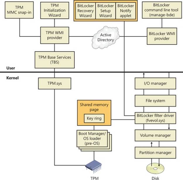
Figure 9-19. BitLocker architecture
Encryption Keys
BitLocker encrypts the contents of the volume using a full-volume encryption key (FVEK) and cryptography that uses the AES128-CBC (by default) or AES256-CBC algorithm, with a Microsoft-specific extension called a diffuser. In turn, the FVEK is encrypted with a volume master key (VMK) and stored in a special metadata region of the volume. Securing the volume master key is an indirect way of protecting data on the volume: the addition of the volume master key allows the system to be rekeyed easily when keys upstream in the trust chain are lost or compromised. This ability to rekey the system saves the time and expense of decrypting and re-encrypting the entire volume again.
When you configure BitLocker, you have a number of options for how the VMK will be protected, depending on the system’s hardware capabilities. If the system has a TPM, you can encrypt the VMK with the TPM, have the system encrypt the VMK using a key stored in the TPM and one stored on a USB flash device, encrypt the VMK using a TPM-stored key and a PIN you enter when the system boots, or encrypt the VMK with a combination of both a PIN and a USB flash device. For systems that don’t have a compatible TPM, BitLocker offers the option ofencrypting the VMK using a key stored on an external USB flash device.
In any case you’ll need an unencrypted 100-MB NTFS system volume, the volume where the Boot Manager and BCD are stored, because the MBR and boot-sector code are legacy code, run in 16-bit real mode (as discussed in Chapter 13), and do not have the ability to perform any on-the-fly decryption of the same volume they’re running on. This means that these components must remain on an unencrypted volume so that the BIOS can access them and they can run and locate Bootmgr.
As covered earlier in this chapter, the system volume is created automatically when Windows is installed on a system, regardless of whether or not you are using BitLocker. This places the system volume at the beginning of the disk (the first partition), which keeps the rest of the disk contiguous.
Figure 9-20 and Table 9-1 summarize the various ways in which the VMK can be generated.
Table 9-1. VMK Sources
|
Source |
Identifies |
Security |
User Impact |
|
TPM only |
What it is |
Protects against software attacks, but vulnerable to hardware attacks. |
None |
|
TPM + PIN |
What it is + What you know |
Adds protection against most hardware attacks as well. |
User must enter PIN each boot |
|
TPM + USB key |
What it is + What you have |
Fully protects against hardware attacks, but vulnerable to stolen USB key. |
User must insert USB key each boot |
|
TPM + USB key + PIN |
What it is + What you have + What you know |
Maximum level of protection. |
User must enter PIN and insert USB key each boot |
|
USB key only |
What you have |
Minimum level of protection for systems without TPM, but vulnerable to stolen key. |
User must insert USB key each boot |
Finally, BitLocker also provides a simple encryption-based authentication scheme to ensure the integrity of the drive contents. Although AES encryption is currently considered uncrackable through brute-force attacks and is one of the most widely used algorithms in the industry today, it doesn’t provide a way to ensure that modified encrypted data can’t in some way be modified such that it is translated back to plaintext data that an attacker could make use of. For example, by precise manipulation of the encrypted data, a hacker might be able to cause a certain logon function to behave differently and allow all logons.
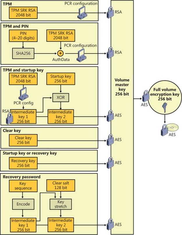
Figure 9-20. BitLocker key generation
To protect the system against this type of attack, BitLocker includes a diffuser algorithm called Elephant. The job of the diffuser is to make sure that even a single bit change in the ciphertext (encrypted data) will result in a totally random plaintext data output, ensuring that the modified executable code will most likely arbitrarily crash instead of performing a specific malicious function. Additionally, when combined with code integrity (see Chapter 3 in Part 1 for more information on code integrity), the diffuser will also cause core system files to fail their signature checks, rendering the system unbootable.
Trusted Platform Module (TPM)
A TPM is a tamper-resistant processor mounted on a motherboard that provides various cryptographic services such as key and random number generation and sealed storage. Support for TPM in Windows reaches beyond supporting BitLocker, however. Through the TPM Base Services (TBS), other applications on the system can also take advantage of compatible hardware TPM chips and use WMI to administer and script access to the TPM. For example, Windows uses a TPM as an additional seed into random number generation, which enhances the overall security of all applications on the system that depend on strong security or hashing algorithms (including mechanisms such as logons).
Although your computer may have a TPM, that does not necessarily mean that Windows will be able to support it. There are two requirements for Windows TPM support:
§ The computer must have a TPM version 1.2 or higher.
§ The computer must have a Trusted Computing Group (TCG)–compliant BIOS. The BIOS establishes a chain of trust for the preboot environment and must include support for TCG-specific Static Root of Trust Measurement (SRTM).
The easiest way to determine whether your machine contains a compatible TPM is to run the TPM MMC snap-in (%SystemRoot%\System32\Tpm.msc). If Windows detects a compatible TPM, you should see a window similar to the one shown in Figure 9-21. Otherwise, an error message will appear.
As stated earlier, BitLocker can be configured to use the TPM to perform system integrity checks on critical early boot components. At a high level, the TPM collects and stores measurements from multiple early boot components and boot configuration data to create a system identifier (much like a fingerprint) for that computer. It stores each part of this fingerprint as a hash in a 160-bit platform configuration register (PCR). BitLocker uses the hash of these functions to seal the VMK, which is the key that BitLocker uses to protect other keys, including the FVEKs used to encrypt volumes.
If the early boot components are changed or tampered with, such as by changing the BIOS or MBR, changing an operating system file, or moving the hard disk to a different computer, the TPM prevents BitLocker from unsealing the VMK, and Windows enters a key recovery mode (described later in the chapter). If the PCR values match those used to seal the key, the system is deemed to be tamper free, and it unseals the key, and BitLocker can decrypt the keys used to encrypt the volumes. Once the keys are unsealed, Windows starts and system protection becomes the responsibility of the user and the operating system.
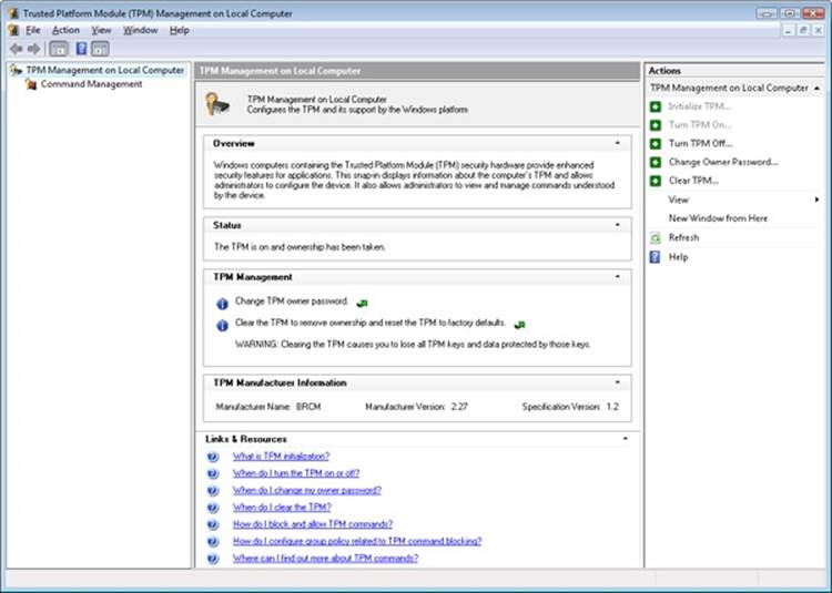
Figure 9-21. The TPM MMC snap-in after initializing the TPM.
A platform validation profile supported by TPMs consists of at least 16, and as many as 24, PCRs that contain additional information and only reset after a TPM reset (implying a machine reboot). Each PCR is associated with components that run when an operating system starts, as shown in Table 9-2.
Table 9-2. Platform Configuration Registers
|
Index |
Meaning |
|
0 |
Core Root of Trust of Measurement (CRTM), BIOS, and platform extensions |
|
1 |
Platform and motherboard configuration and data (BIOS data and CPU microcode) |
|
2 |
Option ROM code |
|
3 |
Option ROM configuration and data |
|
4 |
Master Boot Record (MBR) code |
|
5 |
Master Boot Record (MBR) partition table |
|
6 |
Power-state transition and wake events |
|
7 |
Computer manufacturer-specific |
|
8 |
First NTFS boot sector (volume boot record) |
|
9 |
Remaining NTFS boot sectors (volume boot record) |
|
10 |
Boot Manager |
|
11 |
BitLocker Access Control |
|
12 |
Defined for use by the static operating system |
|
13 |
Defined for use by the static operating system |
|
14 |
Defined for use by the static operating system |
|
15 |
Defined for use by the static operating system |
|
16 |
Used for debugging |
|
17 |
Dynamic CRTM |
|
18 |
Platform defined |
|
19 |
Used by a trusted operating system |
|
20 |
Used by a trusted operating system |
|
21 |
Used by a trusted operating system |
|
22 |
Used by a trusted operating system |
|
23 |
Application support |
By default, BitLocker uses registers 0, 2, 4, 5, 8, 9, 10, and 11 to seal the VMK. The set of PCRs used by BitLocker is known as the Platform Validation Profile, which can be configured via Group Policy (Computer Configuration\Administrative Templates\WindowsComponents\BitLocker Drive Encryption\Operating System Drives\Configure TPM platform validation profile) and depends on the security requirements of your organization, as shown in Table 9-2. PCR 11 must be selected to enable BitLocker protection.
NOTE
If you change anything protected by the PCRs specified in your Platform Validation Profile, your system will not boot without either the recovery key or recovery password. For example, if you need to update the BIOS on your system, suspend BitLocker (using the BitLocker Drive Encryption Control Panel applet) before performing the update.
BitLocker Boot Process
The actual measurements stored in the TPM PCRs are generated by the TPM itself, the TPM BIOS, and Windows. When the system boots, the TPM does a self-test, following which the CRTM in the BIOS measures its own hashing and PCR loading code and writes the hash to the first PCR of the TPM. It then hashes the BIOS and stores that measurement in the first PCR as well. The BIOS in turn hashes the next component in the boot sequence, the MBR of the boot drive, and this process continues until the operating system loader is measured. Each subsequent piece of code that runs is responsible for measuring the code that it loads and for storing the measurement in the appropriate PCR in the TPM.
Finally, when the user selects which operating system to boot, the Boot Manager (Bootmgr) reads the encrypted VMK from the volume and asks the TPM to unseal it. As described previously, only if all the measurements are the same as when the VMK was sealed, including the optional PIN (password), will the TPM successfully decrypt the VMK. This process not only guarantees that the machine and system files are identical to the applications or operating systems that are allowed to read the drive, but also verifies the uniqueness of the operating system installation. For example, even another identical Windows operating system installed on the same machine will not get access to the drive because Bootmgr takes an active role in protecting the VMK from being passed to an operating system to which it doesn’t belong (by generating a MAC hash of several system configuration options).
You can think of this scheme as a verification chain, where each component in the boot sequence describes the next component to the TPM. In effect, the TPM acts like a safe with 12 combination dials, with each dial containing 2,160 numbers. Only if all the PCRs match the original ones given to it when BitLocker was enabled will the TPM divulge its secret. BitLocker therefore protects the encrypted data even when the disk is removed and placed in another system, the system is booted using a different operating system, or the unencrypted files on the boot volume are compromised. Figure 9-22 shows the various steps of the preboot process up until Winload begins loading the operating system.
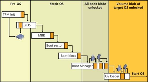
Figure 9-22. BitLocker preboot process
The administrator may need to temporarily suspend BitLocker protection because a component specified in the Platform Validation Profile needs to be changed (for example, updating BIOS, changing a drive’s partition table, installing another operating system on the same disk, and so on). The BitLocker Drive Encryption Control Panel applet provides a simple mechanism for suspending BitLocker (click Suspend Protection for the volume). When BitLocker is suspended, the contents of the volume are still encrypted, but the volume master key is encrypted with a symmetric clear key, which is written to the volume’s BitLocker metadata. When a volume is mounted, BitLocker automatically looks for a clear key and will be able to decrypt the contents of the volume. When BitLocker protection on a volume is resumed, the clear key is removed from the metadata.
NOTE
Exposing the volume master key even for a brief period of time is a security risk because an attacker could access the volume master key and FVEK when these keys were exposed by the clear key, so do not leave a volume suspended for any longer than absolutely necessary.
BitLocker Key Recovery
For recovery purposes, BitLocker uses a recovery key (stored on a USB device) or a recovery password (numerical password), as shown earlier in Figure 9-20. BitLocker creates the recovery key and recovery password during initialization. A copy of the VMK is encrypted with a 256-bit AES-CCM key that can be computed with the recovery password and a salt stored in the metadata block. The password is a 48-digit number, eight groups of 6 digits, with three properties for checksumming:
§ Each group of 6 digits must be divisible by 11. This check can be used to identify groups mistyped by the user.
§ Each group of 6 digits must be less than 216 * 11. Each group contains 16 bits of key information. The eight groups, therefore, hold 128 bits of key.
§ The sixth digit in each group is a checksum digit.
Inserting the recovery key or typing the recovery password enables an authorized user to regain access to the encrypted volume in the event of an attempted security breach or system failure. Figure 9-23 displays the prompt requesting the user to type the recovery password.
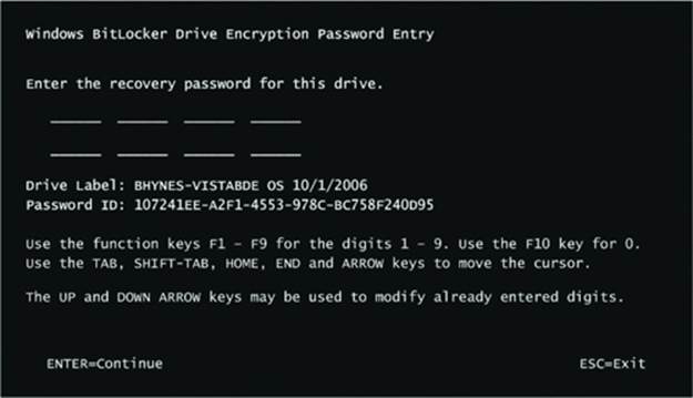
Figure 9-23. BitLocker recovery screen
The recovery key or password is also used in cases when parts of the system have changed, resulting in different measurements. One common example of this is when a user has modified the BCD, such as by adding the debug option. Upon reboot, Bootmgr will detect the change and ask the user to validate it by inputting the recovery key. For this reason, it is extremely important not to lose this key, because it isn’t only used for recovery but for validating system changes. Another application of the recovery key is for foreign volumes. Foreign volumes are operating system volumes that were BitLocker-enabled on another computer and have been transferred to a different Windows computer. An administrator can unlock these volumes by entering the recovery password.
Full-Volume Encryption Driver
Unlike EFS, which is implemented by the NTFS file system driver and operates at the file level, BitLocker encrypts at the volume level using the full-volume encryption (FVE) driver (%SystemRoot%\System32\Drivers\Fvevol.sys), as shown in Figure 9-24.
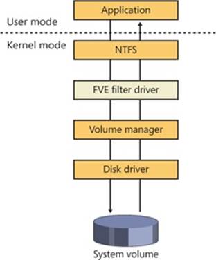
Figure 9-24. BitLocker filter driver implementation
FVE is a filter driver, so it automatically sees all the I/O requests sent to the volume, encrypting blocks as they’re written and decrypting them as they’re read using the FVEK assigned to the volume when it’s initially configured to use BitLocker. Because the encryption and decryption happen beneath NTFS in the I/O system, the volume appears to NTFS as if it’s unencrypted, and NTFS is not aware that BitLocker is enabled. If you attempt to read data from the volume from outside Windows, however, it appears to be random data.
BitLocker also uses an extra measure to make plaintext attacks in which an attacker knows the contents of a sector and uses that information to try and derive the key used to encrypt it more difficult. By combining the FVEK with the sector number to create the key used to encrypt a particular sector, and passing the encrypted data through the Elephant diffuser, BitLocker ensures that every sector is encrypted with a slightly different key, resulting in different encrypted data for different sectors even if their contents are identical.
BitLocker encrypts every sector (including unallocated sectors) on a volume with the exception of the first sector and three unencrypted metadata blocks containing the encrypted VMK and other data used by BitLocker. The metadata is surfaced in the volume’s System Volume Information directory.
BitLocker Management
BitLocker provides a variety of administrative interfaces, each suited to a particular role or task. It provides a WMI interface (and works with the TBS—TPM Base Services—WMI interface) for programmatic access to the BitLocker functionality, a set of group policies that allow administrators to define the behavior across the network or a series of machines, integration with Active Directory, and a command-line management program (%SystemRoot%\System32\Manage-bde.exe).
Developers and system administrators with scripting familiarity can access the Win32_Tpm and Win32_EncryptableVolume interfaces to protect keys, define authentication methods, define which PCR registers are used as part of the BitLocker Platform Validation Profile, and manually initiate encryption or decryption of an entire volume. The Manage-bde.exe program, located in %SystemRoot%\System32, uses these interfaces to allow command-line management of the BitLocker service.
On systems that are joined to a domain, the key for each machine can automatically be backed up as part of a key escrow service, allowing IT administrators to easily recover and gain access to machines that are part of the corporate network. Additionally, various group policies related to BitLocker can be configured. You can access these by using the Local Group Policy Editor, under the Computer Configuration, Administrative Templates, Windows Components, BitLocker Drive Encryption entry. For example, Figure 9-25 displays the option for enabling the Active Directory key backup functionality.
If a TPM chip is present on the system, additional options (such as TPM Key Backup) can be accessed from the Trusted Platform Module Services entry under Windows Components.
To ensure easy access to corporate data, the Data Recovery Agent (DRA) feature has been added to BitLocker. The DRA is most commonly configured via Group Policy and allows a certificate to be specified as a key protector. This allows anyone holding that certificate (or a smartcard containing the certificate) to access (or unlock) a BitLocker-protected volume. See http://technet.microsoft.com/en-us/library/dd875560(WS.10).aspx for more information on configuring DRA.
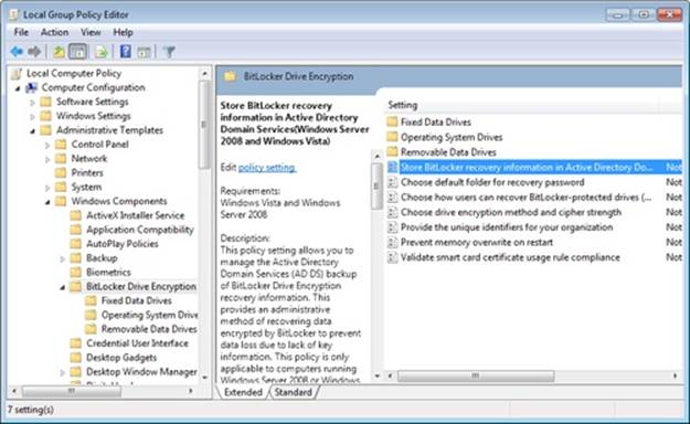
Figure 9-25. BitLocker Group Policy settings
BitLocker To Go
USB flash disks have become a popular method for transporting data because of their small size, low cost, and large capacity. However, it is precisely these qualities that make USB flash disks a security threat. Gigabytes of confidential information can be stored on a device the size of an AA battery that is easily lost or stolen. Standard BitLocker only encrypts NTFS volumes, and all USB flash disks use the FAT file system by default. BitLocker To Go (BTG) now brings the security of BitLocker full-volume encryption to disk devices using the FAT file system. BTG-encrypted flash disks can be created only on the Enterprise, Ultimate, or Server editions of Windows. They can be read on any edition—even on older operating systems such as Windows XP and Windows Vista—but can be written only on Windows 7 or Windows Server2008/R2. To ensure that BTG is used, Group Policy can be used to restrict writing to removable media unless it is protected with BTG.
Like standard BitLocker, BTG encrypts the volume using AES, the decryption key is encrypted with multiple key protectors, and a recovery key can be saved to a file or escrowed through Active Directory. Unlike standard BitLocker, BTG does not make use of the TPM or public key cryptography. One of the key protectors may be either a user-supplied password or a smartcard.
BTG can be enabled in Explorer (right-click on the flash disk, and select Turn On BitLocker) or from the BitLocker Control Panel applet. Once it’s enabled, BTG will create a FAT32 discovery volume containing the files shown in Figure 9-26. The purpose of the discovery volume is to provide the stand-alone BitLockerToGo application and its MUI files (user interface strings in various languages) and metadata to the host operating system.
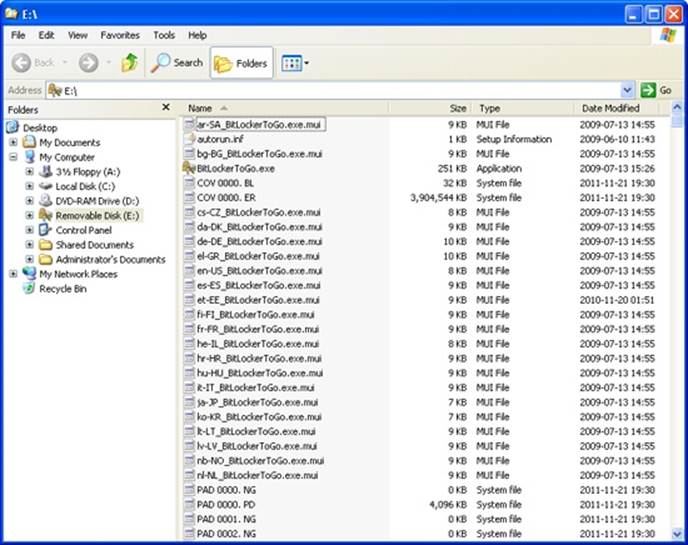
Figure 9-26. BitLocker To Go files
The encrypted volume is implemented as one or more cover files, named COV 0000. ER to COV 9999. ER, each of which can have a maximum size of 4 GB, as shown in Figures Figure 9-26 and Figure 9-27. Any extra space left on the volume will be filled with padding files to prevent any additional files from being added to the discovery volume.
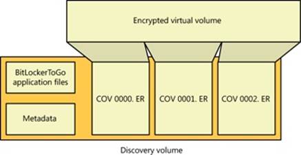
Figure 9-27. BitLocker To Go layout
When the BitLockerToGo application mounts the encrypted virtual volume, the discovery volume will be hidden and is not accessible. The virtual volume may then be accessed like any other disk.
Volume Shadow Copy Service
The Volume Shadow Copy Service (VSS) is a built-in Windows mechanism that enables the creation of consistent, point-in-time copies of data, known as shadow copies or snapshots. VSS coordinates with applications, file-system services, backup applications, fast-recovery solutions, and storage hardware to produce consistent shadow copies.
Shadow Copies
Shadow copies are created through one of two mechanisms—clone and copy-on-write. The VSS provider (described in more detail later) determines the method to use. (Providers can implement the snapshot as they see fit. For example, certain hardware providers will take a hybrid approach: clone first, and then copy-on-write.)
Clone Shadow Copies
A clone shadow copy, also called a split mirror, is a full duplicate of the original data on a volume, created either by software or hardware mirroring. Software or hardware keeps a clone synchronized with the master copy until the mirror connection is broken in order to create a shadow copy. At that moment, the live volume (also called the original volume) and the shadow volume become independent. The live volume is writable and still accepts changes, but the shadow volume is read-only and stores contents of the live volume at the time it was created.
Copy-on-Write Shadow Copies
A copy-on-write shadow copy, also called a differential copy, is a differential, rather than a full, duplicate of the original data. Similar to a clone copy, differential copies can be created by software or hardware mechanisms. Whenever a change is made to the live data, the block of data being modified is copied to a “differences area” associated with the shadow copy before the change is written to the live data block. Overlaying the modified data on the live data creates a view of the live data at the point in time when the shadow copy was created.
NOTE
The in-box VSS provider that ships with Windows supports only copy-on-write shadow copies.
VSS Architecture
VSS (%SystemRoot%\System32\Vssvc.exe) coordinates VSS writers, VSS providers, and VSS requestors. A VSS writer is a software component that enables shadow-copy-aware applications, such as Microsoft SQL Server, Microsoft Exchange Server, and Active Directory, to receive freeze and thaw notifications to ensure that backup copies of their data files are internally consistent. Implementing a VSS provider allows an ISV or IHV with unique storage schemes to integrate with the shadow copy service. For instance, an IHV with mirrored storage devices might define a shadow copy as the frozen half of a split mirrored volume. VSS requestors are the applications that request the creation of volume shadow copies and include backup utilities and the Windows System Restore feature. Figure 9-28 shows the relationship between the VSS shadow copy service, writers, providers, and requestors.
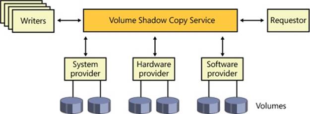
Figure 9-28. VSS architecture
VSS Operation
Regardless of the specific purpose for the copy and the application making use of VSS, shadow copy creation follows the same steps, shown in Figure 9-29. First, a requestor sends a command to VSS to enumerate writers, gather metadata, and prepare for the copy (1). VSS asks each writer to return information on its restore capabilities and an XML description of its backup components (2). Next, each writer prepares for the copy in its own appropriate way, which might include completing outstanding transactions and flushing caches. A prepare command is sent to all involved providers as well (3).
At this point, VSS initiates the commit phase of the copy (4). VSS instructs each writer to quiesce its data and temporarily freeze all write I/O requests (read requests are still passed through). VSS then flushes volume file system buffers and requests that the volume file system drivers freeze their I/O by sending them the IOCTL_VOLSNAP_FLUSH_AND_HOLD_WRITES device I/O control command, ensuring that all the file system metadata is written out to disk consistently (5). Once the system is in this state, VSS sends a command telling the provider to perform the actual copy creation (6). VSS allows up to 10 seconds for the creation, after which it aborts the operation if it is not already completed in this interval. After the provider has created the shadow copy, VSS asks the file systems to thaw, or resume write I/O operations, by sending them the IOCTL_VOLSNAP_RELEASE_WRITES command, and it releases the writers from their temporary freeze. All queued write I/O operations then proceed (7).
VSS next queries the writers to confirm that I/O operations were successfully held during the creation to ensure that the created shadow copy is consistent. If the shadow copy is inconsistent as the result of file system damage, the shadow copy is deleted by VSS. In other cases of writer failure, VSS simply notifies the requestor. At this point, the requestor can retry the procedure from (1) or wait for user action. If the copy was created consistently, VSS tells the requestor the location of the copy.
An optional final step is to make the snapshot device(s) writable, such that interested writers such as TxF (transactional NTFS) can perform additional recovery actions on the snapshot device itself. After this recovery step, the snapshot is sealed read-only and handed out to the requestor.
NOTE
VSS also allows the surfacing of shadow copy devices on a different server—called transportable shadow copies.
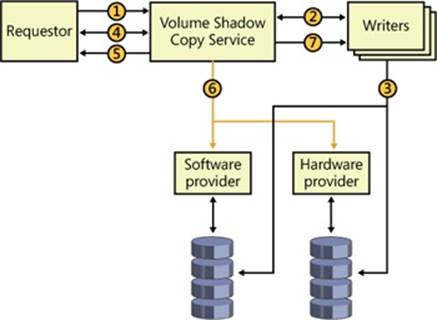
Figure 9-29. VSS shadow copy creation
Shadow Copy Provider
The Shadow Copy Provider (%SystemRoot%\System32\Drivers\Swprov.dll) implements software-based differential copies with the aid of the Volume Shadow Copy Driver (Volsnap—%SystemRoot%\System32\Drivers\Volsnap.sys). Volsnap is a storage filter driver that resides between file system drivers and volume manager drivers (the drivers that present views of the sectors that represent a volume) so that the I/O system forwards it I/O operations directed at a volume.
When asked by VSS to create a shadow copy, Volsnap queues I/O operations directed at the target volume and creates a differential file in the volume’s System Volume Information directory to store volume data that subsequently changes. Volsnap also creates a virtual volume through which applications can access the shadow copy. For example, if a volume’s name in the object manager namespace is \Device\HarddiskVolume1, the shadow volume would have a name like \Device\HarddiskVolumeShadowCopyN, where N is a unique ID.
Whenever Volsnap sees a write operation directed at a live volume, it reads a copy of the sectors that will be overwritten into a paging file—a backed memory section that’s associated with the corresponding shadow copy. It services read operations directed at the shadow copy of modified sectors from this memory section, and it services reads to unmodified areas by reading from the live volume. Because the backup utility won’t save the paging file or the contents of the system-managed System Volume Information directory located on every volume (which includes shadow copy differential files), Volsnap uses the defragmentation API to determine the location of these files and directories and does not record changes to them.
Figure 9-30 demonstrates the behavior of applications accessing a volume and a backup application accessing the volume’s shadow volume copy. When an application writes to a sector after the snapshot time, the Volsnap driver makes a backup copy, like it has for sectors a, b, and c of volume C: in the figure. Subsequently, when an application reads from sector c, Volsnap directs the read to volume C:, but when a backup application reads from sector c, Volsnap reads the sector from the snapshot. When a read occurs for any unmodified sector, such as d, Volsnap routes the read to volume C:.
NOTE
Volsnap avoids copy-on-write operations for the paging file, hibernation file, and the difference data stored in the System Volume Information folder. All other files will get copy-on-write protection.

Figure 9-30. Volsnap operation
EXPERIMENT: LOOKING AT MICROSOFT SHADOW COPY PROVIDER FILTER DEVICE OBJECTS
You can see the Microsoft Shadow Copy Provider driver’s device objects attached to each volume device on a Windows system in a kernel debugger. Every system has at least one volume, and the following command displays the device object of the first volume on a system:
1: kd> !devobj \device\harddiskvolume1
Device object (88cfd908) is for:
HarddiskVolume1 \Driver\volmgr DriverObject 8861a550
Current Irp 00000000 RefCount 3274 Type 00000007 Flags 00201150
Vpb 88cfc3f8 Dacl 8bbcf7ec DevExt 88cfd9c0 DevObjExt 88cfdaa8 Dope
88cfdb38 DevNode 88cfc008
ExtensionFlags (0x00000800) DOE_DEFAULT_SD_PRESENT
Characteristics (0000000000)
AttachedDevice (Upper) 88cfd3b8 \Driver\fvevol
Device queue is not busy.
1: kd> !devstack 88cfd908
!DevObj !DrvObj !DevExt ObjectName
88d015a0 \Driver\volsnap 88d01658
88cfc478 \Driver\rdyboost 88cfc530
88cfd3b8 \Driver\fvevol 88cfd470
> 88cfd908 \Driver\volmgr 88cfd9c0 HarddiskVolume1
!DevNode 88cfc008 :
DeviceInst is "STORAGE\Volume\{53ffaec4-5e9c-11e1-a633-806e6f6e6963}#0000000000100000"
ServiceName is "volsnap"
The address of HarddiskVolume1’s device object (88cfd908) is passed to the !devstack command, which displays the device objects layered on top of it.
Uses in Windows
Several features in Windows make use of VSS, including Backup, System Restore, Previous Versions, and Shadow Copies for Shared Folders. We’ll look at some of these uses and describe why VSS is needed and which VSS functionality is applicable to the applications.
Backup
A limitation of many backup utilities relates to open files. If an application has a file open for exclusive access, a backup utility can’t gain access to the file’s contents. Even if the backup utility can access an open file, the utility runs the risk of creating an inconsistent backup. Consider an application that updates a file at its beginning and then at its end. A backup utility saving the file during this operation might record an image of the file that reflects the start of the file before the application’s modification and the end after the modification. If the file is later restored the application might deem the entire file corrupt because it might be prepared to handle the case where the beginning has been modified and not the end, but not vice versa. These two problems illustrate why most backup utilities skip open files altogether.
EXPERIMENT: VIEWING SHADOW VOLUME DEVICE OBJECTS
You can see the existence of shadow volume device objects in the object manager namespace by starting the Windows backup application (under System Tools in the Accessories folder of the Start menu), and then running WinObj to see the objects in the \Device subdirectory, as shown here.
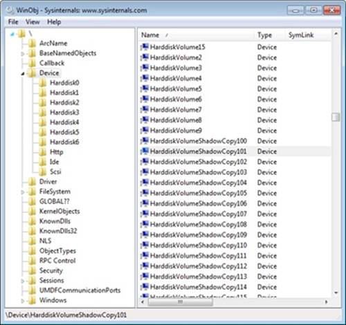
Instead of opening files to back up on the live volume, the backup utility opens them on the shadow volume. A shadow volume represents a point-in-time view of a volume, so by relying on the shadow copy facility, the backup utility overcomes both the backup problems related to open files.
Previous Versions and System Restore
The Windows Previous Versions feature also integrates support for automatically creating volume snapshots, typically one per day, that you can access through Explorer (by opening a Properties dialog box) using the same interface used by Shadow Copies for Shared Folders. This enables you to view, restore, or copy old versions of files and directories that you might have accidentally modified or deleted.
Windows also takes advantage of volume snapshots to unify user and system data-protection mechanisms and avoid saving redundant backup data. When an application installation or configuration change causes incorrect or undesirable behaviors, you can use System Restore torestore system files and data to their state as it existed when a restore point was created. When you use the System Restore user interface in Windows 7 to go back to a restore point, you’re actually copying earlier versions of modified system files from the snapshot associated with the restore point to the live volume.
EXPERIMENT: NAVIGATING THROUGH PREVIOUS VERSIONS
As you saw earlier, each time Windows creates a new system restore point, this results in a shadow copy being taken for that volume. You can use Windows Explorer to navigate through time and see older copies of each drive being shadowed. To see a list of all previous versions of an entire volume, right-click on a partition, such as C:, and select Restore Previous Versions. You will see a dialog box similar to the one shown here.
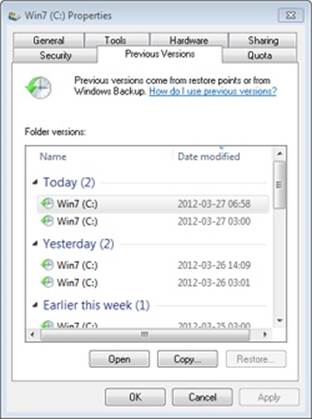
Pick any of the versions shown, and then click the Open button. This opens a new Explorer window displaying that volume at the point in time when the snapshot was taken. The path shown will include localhost\C$\<volume label> (<drive>:) (<date>, <time>), which is how Explorer virtualizes the different shadow copies taken. (C$ is the local hidden default share that Windows networking uses; for more information, see Chapter 7, “Networking,” in Part 1.) Note that Explorer will normally display a path as a friendly name in its address bar. To see the actual path, click once within the address bar.
NOTE
If your disk is drastically low on free space, the space consumed by the shadow copy will be reclaimed, in which case you might not have any previous versions.
Internally, each volume shadow copy shown isn’t a complete copy of the drive, so it doesn’t duplicate the entire contents twice, which would double disk space requirements for every single copy. Previous Versions uses the copy-on-write mechanism described earlier to create shadow copies. For example, if the only file that changed between time A and time B, when a volume shadow copy was taken, is New.txt, the shadow copy will contain only New.txt. This allows VSS to be used in client scenarios with minimal visible impact on the user, since entire drive contents are not duplicated and size constraints remain small.
Although shadow copies for previous versions are taken daily (or whenever a Windows Update or software installation is performed, for example), you can manually request a copy to be taken. This can be useful if, for example, you’re about to make major changes to the system or have just copied a set of files you want to save immediately for the purpose of creating a previous version. You can access these settings by right-clicking Computer on the Start Menu or desktop, selecting Properties, and then clicking System Protection. You can also open Control Panel, click System And Maintenance, and then click System. The dialog box shown in Figure 9-31 allows you to select the volumes on which to enable System Restore (which also affects previous versions) and to create an immediate restore point and name it.
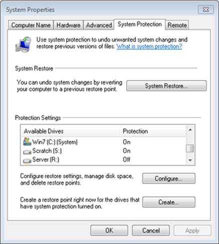
Figure 9-31. System Restore and Previous Versions configuration
EXPERIMENT: MAPPING VOLUME SHADOW DEVICE OBJECTS
Although you can browse previous versions by using Explorer, this doesn’t give you a permanent interface through which you can access that view of the drive in an application-independent, persistent way. You can use the Vssadmin utility (%SystemRoot%\System32\Vssadmin.exe) included with Windows to view all the shadow copies taken, and you can then take advantage of symbolic links to map a copy. This experiment will show you how.
1. List all shadow copies available on the system by using the list shadows command:
vssadmin list shadows
You’ll see output that resembles the following. Each entry is either a previous version copy or a shared folder with shadow copies enabled.
vssadmin 1.1 - Volume Shadow Copy Service administrative command-line tool
(C) Copyright 2001-2005 Microsoft Corp.
Contents of shadow copy set ID: {dfe617b7-ef2b-4280-9f4e-ddf94c2ccfac}
Contained 1 shadow copies at creation time: 8/27/2008 1:59:58 PM
Shadow Copy ID: {f455a794-6b0c-49e4-9ae5-e54647fd1f31}
Original Volume: (C:)\\?\Volume{f5f9d9c3-7466-11dd-9ba5-806e6f6e6963}\
Shadow Copy Volume: \\?\GLOBALROOT\Device\HarddiskVolumeShadowCopy1
Originating Machine: WIN-SL5V78KD01W
Service Machine: WIN-SL5V78KD01W
Provider: 'Microsoft Software Shadow Copy provider 1.0'
Type: ClientAccessibleWriters
Attributes: Persistent, Client-accessible, No auto release,
Differential, Auto recovered
Contents of shadow copy set ID: {02dad996-e7b0-4d2d-9fb9-7e692be8fe3c}
Contained 1 shadow copies at creation time: 8/29/2008 1:51:14 AM
Shadow Copy ID: {79c9ee14-ca1f-4e46-b3f0-0dc98f8eb0d4}
Original Volume: (C:)\\?\Volume{f5f9d9c3-7466-11dd-9ba5-806e6f6e6963}\
Shadow Copy Volume: \\?\GLOBALROOT\Device\HarddiskVolumeShadowCopy2.
...
Note that each shadow copy set ID displayed in this output matches the C$ entries shown by Explorer in the previous experiment (although the date and time may be formatted differently), and the tool also displays the shadow copy volume, which corresponds to the shadow copy device objects that you can see with WinObj.
2. You can now use the Mklink.exe utility to create a directory symbolic link (for more information on symbolic links, see Chapter 12), which will let you map a shadow copy into an actual location. Use the /d flag to create a directory link, and specify a folder on your drive to map to the given volume device object. Make sure to append the path with a backslash (\) as shown here:
mklink /d c:\old \\?\GLOBALROOT\Device\HarddiskVolumeShadowCopy2\
3. Finally, with the Subst.exe utility, you can map the c:\old directory to a real volume using the command shown here:
subst g: c:\old
You can now access the old contents of your drive from any application by using the c:\old path, or from any command-prompt utility by using the g:\ path—for example, try dir g: to list the contents of your drive.
Conclusion
In this chapter, we’ve reviewed the on-disk organization, components, and operation of Windows disk storage management. In Chapter 11, we’ll delve into the cache manager, an executive component integral to the operation of file system drivers that mount the volume types presented in this chapter. However, next, we’ll take a close look at an integral component of the Windows kernel: the memory manager.
All materials on the site are licensed Creative Commons Attribution-Sharealike 3.0 Unported CC BY-SA 3.0 & GNU Free Documentation License (GFDL)
If you are the copyright holder of any material contained on our site and intend to remove it, please contact our site administrator for approval.
© 2016-2026 All site design rights belong to S.Y.A.