MCSA: Windows Server 2012 R2 Installation and Configuration (2015)
Chapter 8
Configure TCP/IP
THE FOLLOWING 70-410 EXAM OBJECTIVES ARE COVERED IN THIS CHAPTER:
1. ![]() Configure IPv4 and IPv6 addressing
Configure IPv4 and IPv6 addressing
§ Configure IP address options
§ Configure IPv4 or IPv6 subnetting
§ Configure supernetting
§ Configure interoperability between IPv4 and IPv6
§ Configure ISATAP
§ Configure Teredo
In this chapter, I will discuss the most important protocol used in a Microsoft Windows Server 2012 R2 network: Transmission Control Protocol/Internet Protocol (TCP/IP).
TCP/IP is actually two sets of protocols bundled together: the Transmission Control Protocol (TCP) and the Internet Protocol (IP). TCP/IP is a suite of protocols developed by the U.S. Department of Defense’s Advanced Research Projects Agency in 1969.
This chapter is divided into two main topics: First I’ll talk about TCP/IP version 4, and then I’ll discuss TCP/IP version 6. TCP/IP version 4 is still used in Windows Server 2012 R2, and it was the primary version of TCP/IP in all previous versions of Windows. However, TCP/IP version 6 is the new release of TCP/IP, and it has been incorporated into Windows Server 2012 R2.
Understanding TCP/IP
I mentioned that TCP/IP is actually two sets of protocols bundled together: TCP and IP. These protocols sit on a four-layer TCP/IP model.
Details of the TCP/IP Model
The four layers of the TCP/IP model are as follows (see Figure 8.1):
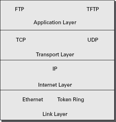
FIGURE 8.1 TCP/IP model
Application Layer The Application layer is where the applications that use the protocol stack reside. These applications include File Transfer Protocol (FTP), Trivial File Transfer Protocol (TFTP), Simple Mail Transfer Protocol (SMTP), and Hypertext Transfer Protocol (HTTP).
Transport Layer The Transport layer is where the two Transport layer protocols reside. These are TCP and the User Datagram Protocol (UDP). TCP is a connection-oriented protocol, and delivery is guaranteed. UDP is a connectionless protocol. This means that UDP does its best job to deliver the message, but there is no guarantee.
Internet Layer The Internet layer is where IP resides. IP is a connectionless protocol that relies on the upper layer (Transport layer) for guaranteeing delivery. Address Resolution Protocol (ARP) also resides on this layer. ARP turns an IP address into a Media Access Control (MAC) address. All upper and lower layers travel through the IP protocol.
Link Layer The data link protocols like Ethernet and Token Ring reside in the Link layer. This layer is also referred to as the Network Access layer.
How TCP/IP Layers Communicate
When an application like FTP is called upon, the application moves down the layers and TCP is retrieved. TCP then connects itself to the IP protocol and gets released onto the network through the Link layer (see Figure 8.2). This is a connection-oriented protocol because TCP is the protocol that guarantees delivery.
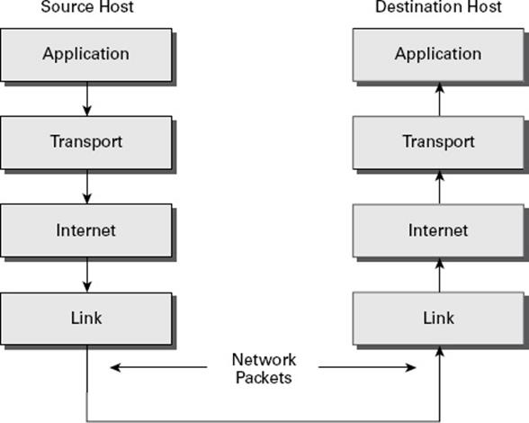
FIGURE 8.2 TCP/IP process
When an application like TFTP gets called, the application moves down the layers and UDP is retrieved. UDP then connects itself to the IP protocol and gets released onto the network through the Link layer. This is a connectionless protocol because UDP does not have guaranteed delivery.
Understanding Port Numbers
TCP and UDP rely on port numbers assigned by the Internet Assigned Numbers Authority (IANA) to forward packets to the appropriate application process. Port numbers are 16-bit integers that are part of a message header. They identify the application software process with which the packet should be associated. For example, let’s say that a client has a copy of Internet Explorer and a copy of Mail open at the same time. Both applications are sending TCP requests across the Internet to retrieve web pages and email, respectively. How does the computer know which return packets to forward to Internet Explorer and which packets to forward to Mail?
When making a connection, the client chooses a source port for the communication that is usually in the range 1024–65535 (or sometimes in the range 1–65535). This source port then communicates with a destination port of 80 or 110 on the server side. Every packet destined for Internet Explorer has a source port number of 80 in the header, and every packet destined for Mail has a source port number of 110 in the header.
Table 8.1 describes the most common port numbers (you might need to know these for the exam). You can visit www.iana.org to get the most current and complete list of port numbers. It’s good to become familiar with specific port numbers because it’s a benefit to be able to determine from memory the ports that, for example, allow or block specific protocols in a firewall. Allowing only port 80, for instance, does not ensure that all web traffic will be allowed. You must also allow port 443 for certain secure web traffic.
TABLE 8.1 Common port numbers
|
Port number |
Description |
|
20 |
FTP data |
|
21 |
FTP control |
|
23 |
Telnet |
|
25 |
Simple Mail Transfer Protocol (SMTP) |
|
53 |
Domain Name System (DNS) |
|
80 |
Hypertext Transfer Protocol (HTTP), Web |
|
88 |
Kerberos |
|
110 |
Post Office Protocol v3 (POP3) |
|
443 |
Secure HTTP (HTTPS) |
 Simply because a port is “well known” doesn’t mean that a given service must run on it. It’s technically valid to run any service on any port, but doing so is usually a bad idea. For example, if you chose to run your web server on TCP port 25, clients would need to type www.example.com:25 to reach your website from most browsers.
Understanding IP Addressing
Understanding IP addressing is critical to understanding how IP works. An IP address is a numeric identifier assigned to each device on an IP network. This type of address is a logical software address that designates the device’s location on the network. It isn’t the physical hardware address hard-coded in the device’s network interface card.
In the following sections, you will see how IP addresses are used to identify uniquely every machine on the network (MAC address).
The Hierarchical IP Addressing Scheme
An IP address consists of 32 bits of information. These bits are divided into four sections (sometimes called octets or quads) containing 1 byte (8 bits) each. There are three common methods for specifying an IP address:
§ Dotted-decimal, as in 130.57.30.56
§ Binary, as in 10000010.00111001.00011110.00111000
§ Hexadecimal, as in 82 39 1E 38
All of these examples represent the same IP address.
The 32-bit IP address is a structured, or hierarchical, address as opposed to a flat, or nonhierarchical, address. Although IP could have used either flat addressing or hierarchical addressing, its designers elected to use the latter for a very good reason, as you will now see.
![]()
Why Hierarchical Addressing Is Used
What’s the difference between flat and hierarchical addressing? A good example of a flat addressing scheme is a U.S. state driver’s license number. There’s no partitioning to it; the range of legal numbers isn’t broken up in any meaningful way (say, by county of residence or date of issue). If this method had been used for IP addressing, every machine on the Internet would have needed a totally unique address, just as each driver’s license number in a particular state is unique.
The good news about flat addressing is that it can handle a large number of addresses in 32 bits of data, namely, 4.3 billion. A 32-bit address space with two possible values for each position—either 0 (zero) or 1 (one)—gives you 232 values, which equals approximately 4.3 billion.
The bad news—and the reason flat addressing isn’t used in IP—relates to routing. If every address were totally unique, every router on the Internet would need to store the address of every other machine on the Internet. It would be fair to say that this would make efficient routing impossible, even if only a fraction of the possible addresses were used.
The solution to this dilemma is to use a hierarchical addressing scheme that breaks the address space into ordered chunks. Telephone numbers are a great example of this type of addressing. The first section of a U.S. telephone number, the area code, designates a very large area. The area code is followed by the prefix, which narrows the scope to a local calling area. The final segment, the customer number, zooms in on the specific connection. By looking at a number such as 603-766-xxxx, you can quickly determine that the number is located in the southern part of New Hampshire (area code 603) in the Portsmouth area (the 766 exchange).
IP Address Structure
IP addressing works the same way. Instead of the entire 32 bits being treated as a unique identifier, one part of the IP address is designated as the network address (or network ID) and the other part as a node address (or host ID), giving it a layered, hierarchical structure. Together, the IP address, the network address, and the node address uniquely identify a device within an IP network.
The network address—the first two sets of numbers in an IP address—uniquely identifies each network. Every machine on the same network shares that network address as part of its IP address, just as the address of every house on a street shares the same street name. In the IP address 130.57.30.56, for example, 130.57 is the network address.
The node address—the second two sets of numbers—is assigned to, and uniquely identifies, each machine in a network, just as each house on the same street has a different house number. This part of the address must be unique because it identifies a particular machine—an individual, as opposed to a network. This number can also be referred to as a host address. In the sample IP address 130.57.30.56, the node address is .30.56.
Understanding Network Classes
The designers of the Internet decided to create classes of networks based on network size. For the small number of networks possessing a very large number of nodes, they created the Class A network. At the other extreme is the Class C network, reserved for the numerous networks with small numbers of nodes. The class of networks in between the very large and very small ones is predictably called the Class B network.
The default subdivision of an IP address into a network and node address is determined by the class designation of your network. Table 8.2 summarizes the three classes of networks, which will be described in more detail in the following sections.
TABLE 8.2 Network address classes
|
Class |
Mask bits |
Leading bit pattern |
Decimal range of first octet of IP address |
Assignable networks |
Maximum nodes per network |
|
A |
8 |
0 |
1–126 |
126 |
16,777,214 |
|
B |
16 |
10 |
128–191 |
16,384 |
65,534 |
|
C |
24 |
110 |
192–223 |
2,097,152 |
254 |
 Classless Inter-Domain Routing (CIDR), explained in detail later in this chapter, has effectively done away with these class designations. You will still hear and should still know the meaning behind the class designations of addresses because they are important to understanding IP addressing. However, when you’re working with IP addressing in practice, CIDR is more important to know.
To ensure efficient routing, Internet designers defined a mandate for the leading bits section of the address for each different network class. For example, because a router knows that a Class A network address always starts with a 0, it can quickly apply the default mask, if necessary, after reading only the first bit of the address. Table 8.2 illustrates how the leading bits of a network address are defined. When considering the subnet masking between network and host addresses, the number of bits to mask is important. For example, in a Class A network, 8 bits are masked, making the default subnet mask 255.0.0.0; in a Class C, 24 bits are masked, making the default subnet mask 255.255.255.0.
Some IP addresses are reserved for special purposes and shouldn’t be assigned to nodes. Table 8.3 describes some of the reserved IP addresses. See RFC 3330 for others.
TABLE 8.3 Special network addresses
|
Address |
Function |
|
Entire IP address set to all 0s |
Depending on the mask, this network (that is, the network or subnet of which you are currently a part) or this host on this network. |
|
A routing table entry of all 0s with a mask of all 0s |
Used as the default gateway entry. Any destination address masked by all 0s produces a match for the all 0s reference address. Because the mask has no 1s, this is the least desirable entry, but it will be used when no other match exists. |
|
Network address 127 |
Reserved for loopback tests. Designates the local node, and it allows that node to send a test packet to itself without generating network traffic. |
|
Node address of all 0s |
Used when referencing a network without referring to any specific nodes on that network. Usually used in routing tables. |
|
Node address of all 1s |
Broadcast address for all nodes on the specified network, also known as a directed broadcast. For example, 128.2.255.255 means all nodes on the Class B network 128.2. Routing this broadcast is configurable on certain routers. |
|
169.254.0.0 with a mask of 255.255.0.0 |
The “link-local” block used for autoconfiguration and communication between devices on a single link. Communication cannot occur across routers. Microsoft uses this block for Automatic Private IP Addressing (APIPA). |
|
Entire IP address set to all 1s (same as 255.255.255.255) |
Broadcast to all nodes on the current network; sometimes called a limited broadcast or an all-1s broadcast. This broadcast is not routable. |
|
192.168.0.0/16 |
The private-use blocks for Classes A, B, and C. As noted in RFC 1918, the addresses in these blocks must never be allowed into the Internet, making them acceptable for simultaneous use behind NAT servers and non-Internet-connected IP networks. |
In the following sections, you will look at the three network types.
Class A Networks
In a Class A network, the first byte is the network address, and the three remaining bytes are used for the node addresses. The Class A format is Network.Node.Node.Node.
For example, in the IP address 49.22.102.70, 49 is the network address, and 22.102.70 is the node address. Every machine on this particular network would have the distinctive network address of 49. Within that network, however, you could have a large number of machines.
There are 126 possible Class A network addresses. Why? The length of a Class A network address is 1 byte, and the first bit of that byte is reserved, so 7 bits in the first byte remain available for manipulation. This means that the maximum number of Class A networks is 128. (Each of the 7 bit positions that can be manipulated can be either a 0 or a 1, and this gives you a total of 27 positions, or 128.) But to complicate things further, it was also decided that the network address of all 0s (0000 0000) would be reserved. This means that the actual number of usable Class A network addresses is 128 minus 1, or 127. Also, 127 is a reserved number (a network address of 0 followed by all 1s [0111 1111], so you actually start with 128 addresses minus the 2 reserved, and you’re left with 126 possible Class A network addresses.
Each Class A network has 3 bytes (24 bit positions) for the node address of a machine, which means that there are 224, or 16,777,216, unique combinations. Because addresses with the two patterns of all 0s and all 1s in the node bits are reserved, the actual maximum usable number of nodes for a Class A network is 224 minus 2, which equals 16,777,214.
Class B Networks
In a Class B network, the first 2 bytes are assigned to the network address, and the remaining 2 bytes are used for node addresses. The format is Network.Network.Node.Node.
For example, in the IP address 130.57.30.56, the network address is 130.57, and the node address is 30.56.
The network address is 2 bytes, so there would be 216 unique combinations. But the Internet designers decided that all Class B networks should start with the binary digits 10. This leaves 14 bit positions to manipulate; therefore, there are 16,384 (or 214) unique Class B networks.
This gives you an easy way to recognize Class B addresses. If the first 2 bits of the first byte can be only 10, that gives you a decimal range from 128 up to 191 in the first octet of the IP address. Remember that you can always easily recognize a Class B network by looking at its first byte, even though there are 16,384 different Class B networks. If the first octet in the address falls between 128 and 191, it is a Class B network, regardless of the value of the second octet.
A Class B network has 2 bytes to use for node addresses. This is 216 minus the two patterns in the reserved-exclusive club (all 0s and all 1s in the node bits) for a total of 65,534 possible node addresses for each Class B network.
Class C Networks
The first 3 bytes of a Class C network are dedicated to the network portion of the address, with only 1 byte remaining for the node address. The format is Network.Network.Network.Node.
In the example IP address 198.21.74.102, the network address is 198.21.74, and the node address is 102.
In a Class C network, the first three bit positions are always binary 110. Three bytes, or 24 bits, minus 3 reserved positions leaves 21 positions. There are therefore 221 (or 2,097,152) possible Class C networks.
The lead bit pattern of 110 equates to decimal 192 and runs through 223. Remembering our handy easy-recognition method, this means you can always spot a Class C address if the first byte is in the range 192–223, regardless of the values of the second and third bytes of the IP address.
Each unique Class C network has 1 byte to use for node addresses. This leads to 28, or 256, minus the two special patterns of all 0s and all 1s, for a total of 254 node addresses for each Class C network.
Class D networks, used for multicasting only, use the address range 224.0.0.0 to 239.255.255.255 and are used, as in broadcasting, as destination addresses only. Class E networks (reserved for future use at this point) cover 240.0.0.0 to 255.255.255.255. Addresses in the Class E range are considered within the experimental range.
Subnetting a Network
If an organization is large and has lots of computers or if its computers are geographically dispersed, it makes good sense to divide its colossal network into smaller ones connected by routers. These smaller networks are called subnets. The benefits of using subnets are as follows:
Reduced Network Traffic We all appreciate less traffic of any kind, and so do networks. Without routers, packet traffic could choke the entire network. Most traffic will stay on the local network—only packets destined for other networks will pass through the router and to another subnet. This traffic reduction also improves overall performance.
Simplified Management It’s easier to identify and isolate network problems in a group of smaller networks connected together than within one gigantic one.
Understanding the Benefits of Subnetting
To understand one benefit of subnetting, consider a hotel or office building. Say that a hotel has 1,000 rooms with 75 rooms to a floor. You could start at the first room on the first floor and number it 1; then when you get to the first room on the second floor, you could number it 76 and keep going until you reach room 1,000. But someone looking for room 521 would have to guess on which floor that room is located. If you were to “subnet” the hotel, you would identify the first room on the first floor with the number 101 (1 = Floor 1 and 01 = Room 1), the first room on the second floor with 201, and so on. The guest looking for room 521 would go to the fifth floor and look for room 21.
An organization with a single network address (comparable to the hotel building mentioned in the sidebar “Understanding the Benefits of Subnetting”) can have a subnet address for each individual physical network (comparable to a floor in the hotel building). Each subnet is still part of the shared network address, but it also has an additional identifier denoting its individual subnetwork number. This identifier is called a subnet address.
Subnetting solves several addressing problems:
§ If an organization has several physical networks but only one IP network address, it can handle the situation by creating subnets.
§ Because subnetting allows many physical networks to be grouped together, fewer entries in a routing table are required, notably reducing network overhead.
§ These things combine collectively to yield greatly enhanced network efficiency.
The original designers of the Internet Protocol envisioned a small Internet with only tens of networks and hundreds of hosts. Their addressing scheme used a network address for each physical network. As you can imagine, this scheme and the unforeseen growth of the Internet created a few problems. The following are two examples:
Not Enough Addresses A single network address can be used to refer to multiple physical networks, but an organization can request individual network addresses for each one of its physical networks. If all of these requests were granted, there wouldn’t be enough addresses to go around.
Gigantic Routing Tables If each router on the Internet needed to know about every physical network, routing tables would be impossibly huge. There would be an overwhelming amount of administrative overhead to maintain those tables, and the resulting physical overhead on the routers would be massive (CPU cycles, memory, disk space, and so on). Because routers exchange routing information with each other, an additional, related consequence is that a terrific overabundance of network traffic would result.
Although there’s more than one way to approach these problems, the principal solution is the one that I’ll cover in this book—subnetting. As you might guess, subnetting is the process of carving a single IP network into smaller logical subnetworks. This trick is achieved by subdividing the host portion of an IP address to create a subnet address. The actual subdivision is accomplished through the use of a subnet mask (covered later in the chapter).
In the following sections, you will see exactly how to calculate and apply subnetting.
Implementing Subnetting
Before you can implement subnetting, you need to determine your current requirements and plan on how best to implement your subnet scheme.
How to Determine Your Subnetting Requirements
Follow these guidelines to calculate the requirements of your subnet:
1. Determine the number of required network IDs: one for each subnet and one for each wide area network (WAN) connection.
2. Determine the number of required host IDs per subnet: one for each TCP/IP device, including, for example, computers, network printers, and router interfaces.
3. Based on these two data points, create the following:
§ One subnet mask for your entire network
§ A unique subnet ID for each physical segment
§ A range of host IDs for each unique subnet
How to Implement Subnetting
Subnetting is implemented by assigning a subnet address to each machine on a given physical network. For example, in Figure 8.3, each machine on subnet 1 has a subnet address of 1.
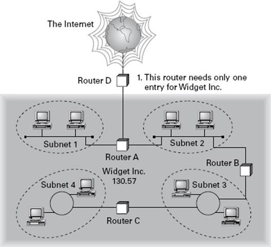
FIGURE 8.3 A sample subnet
The default network portion of an IP address can’t be altered without encroaching on another administrative domain’s address space, unless you are assigned multiple consecutive classful addresses. To maximize the efficient use of the assigned address space, machines on a particular network share the same network address. In Figure 8.3, you can see that all of the Widget Inc. machines have a network address of 130.57. That principle is constant. In subnetting, it’s the host address that’s manipulated—the network address doesn’t change. The subnet address scheme takes a part of the host address and recycles it as a subnet address. Bit positions are stolen from the host address to be used for the subnet identifier. Figure 8.4 shows how an IP address can be given a subnet address.
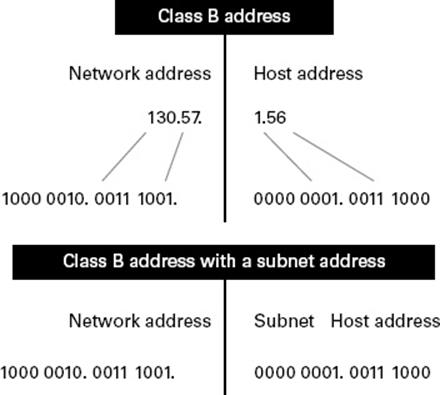
FIGURE 8.4 Network vs. host addresses
Because the Widget Inc. network is a Class B network, the first two bytes specify the network address and are shared by all machines on the network, regardless of their particular subnet. Here every machine’s address on the subnet must have its third byte read 0000 0001. The fourth byte, the host address, is the unique number that identifies the actual host within that subnet. Figure 8.5 illustrates how a network address and a subnet address can be used together.
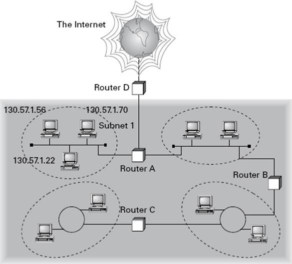
FIGURE 8.5 The network address and its subnet
When implementing subnetting, you need some type of hardware installed onto the network. Most of us will just use a router. But if you do not want to purchase an expensive router, there is another way.
One way that you can implement subnetting is by using a Windows Server 2012 R2 machine with multiple NIC adapters configured with routing enabled on the server. This type of router is called a multihomed router. This is an inexpensive way to set up a router using a Microsoft server, but it may not be the best way. Many companies specialize in routers, and these routers offer many more features and more flexibility than a multihomed router.
How to Use Subnet Masks
For the subnet address scheme to work, every machine on the network must know which part of the host address will be used as the network address. This is accomplished by assigning each machine a subnet mask.
The network administrator creates a 32-bit subnet mask comprising 1s and 0s. The 1s in the subnet mask represent the positions in the IP address that refer to the network and subnet addresses. The 0s represent the positions that refer to the host part of the address. Figure 8.6 illustrates this combination.
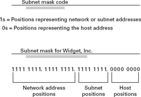
FIGURE 8.6 The subnet mask revealed
In the Widget Inc. example, the first two bytes of the subnet mask are 1s because Widget’s network address is a Class B address, formatted as Network.Network.Node.Node. The third byte, normally assigned as part of the host address, is now used to represent the subnet address. Hence, those bit positions are represented with 1s in the subnet mask. The fourth byte is the only part of the example that represents the host address.
The subnet mask can also be expressed using the decimal equivalents of the binary patterns. The binary pattern of 1111 1111 is the same as decimal 255. Consequently, the subnet mask in the example can be denoted in two ways, as shown in Figure 8.7.
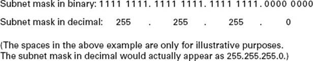
FIGURE 8.7 Different ways to represent the same mask
Not all networks need to have subnets, and therefore they don’t need to use custom subnet masks. In this case, they are said to have a default subnet mask. This is basically the same as saying that they don’t have any subnets except for the one main subnet on which the network is running. Table 8.4 shows the default subnet masks for the different classes of networks.
TABLE 8.4 Default subnet masks
|
Class |
Format |
Default Subnet Mask |
|
A |
Network.Node.Node.Node |
255.0.0.0 |
|
B |
Network.Network.Node.Node |
255.255.0.0 |
|
C |
Network.Network.Network.Node |
255.255.255.0 |
Once the network administrator has created the subnet mask and has assigned it to each machine, the IP software applies the subnet mask to the IP address to determine its subnet address. The word mask carries the implied meaning of “lens” in this case; that is, the IP software looks at its IP address through the lens of its subnet mask to see its subnet address. Figure 8.8 illustrates an IP address being viewed through a subnet mask.
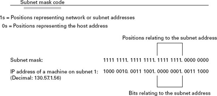
FIGURE 8.8 Applying the subnet mask
In this example, the IP software learns through the subnet mask that, instead of being part of the host address, the third byte of its IP address is now going to be used as a subnet address. The IP software then looks in its IP address at the bit positions that correspond to the mask, which are 0000 0001.
The final step is for the subnet bit values to be matched up with the binary numbering convention and converted to decimal. In the Widget Inc. example, the binary-to-decimal conversion is simple, as illustrated in Figure 8.9.
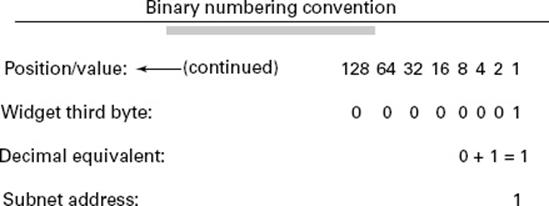
FIGURE 8.9 Converting the subnet mask to decimal
By using the entire third byte of a Class B address as the subnet address, it is easy to set and determine the subnet address. For example, if Widget Inc. wants to have a subnet 6, the third byte of all machines on that subnet will be 0000 0110 (decimal 6 in binary).
Using the entire third byte of a Class B network address for the subnet allows for a fair number of available subnet addresses. One byte dedicated to the subnet provides eight bit positions. Each position can be either a 1 or a 0, so the calculation is 28, or 256. Thus, Widget Inc. can have up to 256 total subnetworks, each with up to 254 hosts.
Although RFC 950 prohibits the use of binary all 0s and all 1s as subnet addresses, today almost all products actually permit this usage. Microsoft’s TCP/IP stack allows it, as does the software in most routers (provided you enable this feature, which sometimes is not the case by default). This gives you two additional subnets. However, you should not use a subnet of 0 (all 0s) unless all the software on your network recognizes this convention.
How to Calculate the Number of Subnets
The formulas for calculating the maximum number of subnets and the maximum number of hosts per subnet are as follows:
2 × number of masked bits in subnet mask = maximum number of subnets
2 × number of unmasked bits in subnet mask – 2 = maximum number of hosts per subnet
In the formulas, masked refers to bit positions of 1, and unmasked refers to bit positions of 0. The downside to using an entire byte of a node address as your subnet address is that you reduce the possible number of node addresses on each subnet. As explained earlier, without a subnet, a Class B address has 65,534 unique combinations of 1s and 0s that can be used for node addresses. The question then is why would you ever want 65,534 hosts on a single physical network?
The trade-off is acceptable to most who ask themselves this question. If you use an entire byte of the node address for a subnet, you then have only 1 byte for the host addresses, leaving only 254 possible host addresses. If any of your subnets are populated with more than 254 machines, you’ll have a problem. To solve it, you would then need to shorten the subnet mask, thereby lengthening the number of host bits and increasing the number of host addresses. This gives you more available host addresses on each subnet. A side effect of this solution is that it shrinks the number of possible subnets.
Figure 8.10 shows an example of using a smaller subnet address. A company called Acme Inc. expects to need a maximum of 14 subnets. In this case, Acme does not need to take an entire byte from the host address for the subnet address. To get its 14 different subnet addresses, it needs to snatch only 4 bits from the host address (24 = 16). The host portion of the address has 12 usable bits remaining (212 – 2 = 4094). Each of Acme’s 16 subnets could then potentially have a total of 4,094 host addresses, and 4,094 machines on each subnet should be plenty.
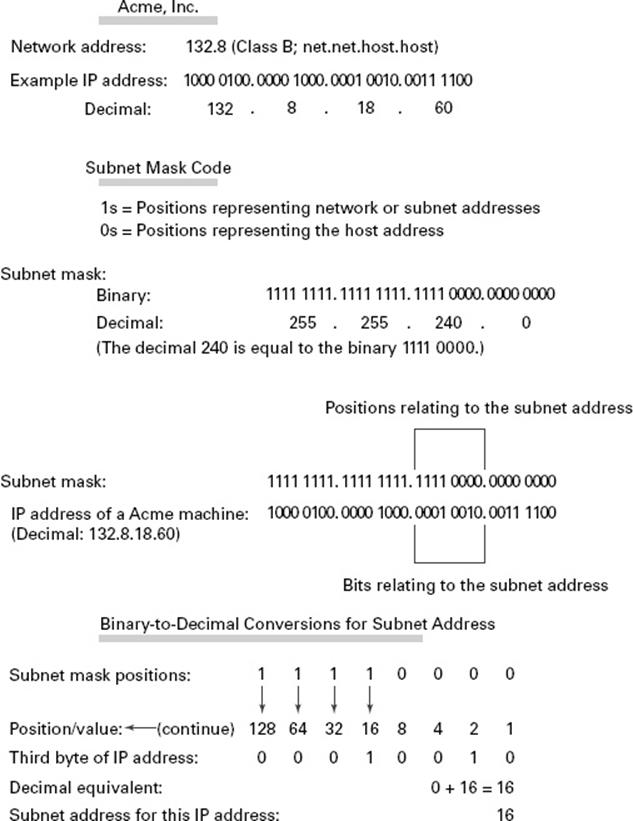
FIGURE 8.10 An example of a smaller subnet address
An Easier Way to Apply Subnetting
Now that you have the basics of how to subnet down, you’ll learn an easier way. If you have learned a different way and it works for you, stick with it. It does not matter how you get to the finish line, just as long as you get there. But if you are new to subnetting,Figure 8.11 will make it easier for you.
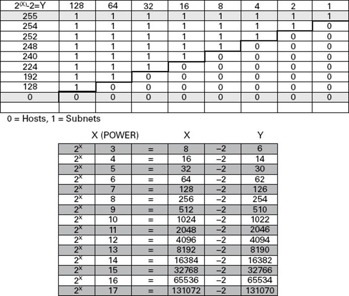
FIGURE 8.11 TCP/IP v4 subnetting chart
This chart may look intimidating, but it’s really simple to use once you have done it a few times.
Remember that, on this chart, 1s equal subnets, and 0s equal hosts. If you get this confused, you will get wrong answers in the following exercises.
Watch the Y column on the lower end of the chart. This represents the number of addresses available to you after the two reserved addresses have been removed. The following exercises provide some examples.
SUBNET MASK EXERCISE 8.1: Class C, 10 Hosts per Subnet
You have a Class C address, and you require 10 hosts per subnet.
1. Write down the following:
255.255.255.____
The blank is the number you need to fill in.
2. Look under the Y column and choose the first number that is larger than 10 (the number of hosts per subnet you need). You should have come up with 14.
3. Move across the page and look at number in the X (Power) column. The power number is 4.
4. Go to the top of the chart and look for the row with exactly four 0s (hosts). Find the number at the beginning of the row.
The number at the beginning of the row is 240. That’s your answer. The subnet mask should be 255.255.255.240.
SUBNET MASK EXERCISE 8.2: Class C, 20 Hosts per Subnet
You have a Class C address, and you need 20 hosts per subnet.
1. Write down the following:
255.255.255.___
2. Look under the Y column and find the first number that covers 20. (This should be 30.)
3. Go across to the power number (5).
4. Go to the top part of the chart and find the row with exactly five 0s from right to left.
The number at the beginning of the row is 224. Your answer should be 255.255.255.224.
SUBNET MASK EXERCISE 8.3: Class C, Five Subnets
Now you have a Class C address, and you need five subnets. Remember that subnets are represented by 1s in the chart.
1. Write down the following:
255.255.255.___
2. Look under the Y column and find the first number that covers 5. (This should be 6.)
3. Go across to the power number. (This should be 3.)
4. Go to the top part of the chart and find out which row has exactly three 1s (remember, 1s are for subnets) from left to right.
Your answer should be 255.255.255.224.
SUBNET MASK EXERCISE 8.4: Class B, 1,500 Hosts per Subnet
This one is a bit harder. You have a Class B address, and you need 1,500 hosts per subnet. Because you have a Class B address, you need to fill in the third octet of numbers. The fourth octet contains eight 0s.
1. Write down the following:
255.255.___.0
2. Look at the Y column and find the first number that covers 1,500. (This should be 2,046.)
3. Go across and find the power number. (This should be 11.)
4. Remember, you already have eight 0s in the last octet. So, you need only three more. Find the row with three 0s.
You should come up with an answer of 255.255.248.0. This actually breaks down to 11111111.11111111.11111000.00000000, and that’s how you got the 11 zeros.
SUBNET MASK EXERCISE 8.5: Class B, 3,500 Hosts per Subnet
You have a Class B address, and you need 3,500 hosts per subnet.
1. Write down the following:
255.255.___.0
2. Look at the Y column and find the first number that covers 3,500. (This should be 4,094.)
3. Go across and find the power number. (This should be 12.)
4. Remember, you already have eight 0s in the last octet, so you need only four more. Count for four zeros from right to left.
You should come up with an answer of 255.255.240.0. Again, this actually breaks down to 11111111.11111111.11110000.00000000, and that’s how you got the 12 zeros.
If you get a question that gives you both the hosts and the subnets, always figure out the larger number first. Then, depending on the mask you have decided to use, make sure that the lower number is also correct with that mask.
Now try some more subnet mask exercises using the data that follows:
|
Class B address |
Class B address |
|
1,000 hosts per subnet |
25 subnets |
|
Class C address |
Class B address |
|
45 hosts per subnet |
4,000 hosts per subnet |
|
192.168.0.0 |
Class B address |
|
10 subnets |
2,000 hosts per subnet |
|
25 subnets |
Here are the answers. If any of your answers are wrong, follow the previous examples and try to work through them again.
|
Class B address |
Class B address |
|
1,000 hosts per subnet 255.255.252.0 |
25 subnets 255.255.248.0 |
|
Class C address |
Class B address |
|
45 hosts per subnet 255.255.255.192 |
4,000 hosts per subnet 255.255.240.0 |
|
192.168.0.0 |
Class B address |
|
10 subnets 255.255.255.240 |
2,000 hosts per subnet |
|
25 subnets 255.255.248.0 |
Applying Subnetting the Traditional Way
Sometimes subnetting can be confusing. After all, it can be quite difficult to remember all of those numbers. You can step back a minute and take a look at the primary classes of networks and how to subnet each one. Let’s start with Class C because it uses only 8 bits for the node address, so it’s the easiest to calculate. In the following sections, I will explain how to subnet the various types of networks.
Subnetting Class C
If you recall, a Class C network uses the first 3 bytes (24 bits) to define the network address. This leaves you 1 byte (8 bits) with which to address hosts. So if you want to create subnets, your options are limited because of the small number of bits available.
If you break down your subnets into chunks smaller than the default Class C, then figuring out the subnet mask, network number, broadcast address, and router address can be confusing. To build a sturdy base for subnetting, study the following techniques for determining these special values for each subnet, but also learn and use the more efficient technique presented in the later section “Quickly Identifying Subnet Characteristics Using CIDR” and the earlier section “An Easier Way to Apply Subnetting.” Table 8.5summarizes how you can break down a Class C network into one, two, four, or eight smaller subnets, and it gives you the subnet masks, network numbers, broadcast addresses, and router addresses. The first three bytes have simply been designated x.y.z. (Note that the table assumes you can use the all-0s and all-1s subnets too.)
TABLE 8.5 Setting up Class C subnets
|
Number of desired subnets |
Subnet mask |
Network number |
Router address |
Broadcast address |
Remaining number of IP addresses |
|
1 |
255.255.255.0 |
x.y.z.0 |
x.y.z.1 |
x.y.z.255 |
253 |
|
2 |
255.255.255.128 |
x.y.z.0 |
x.y.z.1 |
x.y.z.127 |
125 |
|
255.255.255.128 |
x.y.z.128 |
x.y.z.129 |
x.y.z.255 |
125 |
|
|
4 |
255.255.255.192 |
x.y.z.0 |
x.y.z.1 |
x.y.z.63 |
61 |
|
255.255.255.192 |
x.y.z.64 |
x.y.z.65 |
x.y.z.127 |
61 |
|
|
255.255.255.192 |
x.y.z.128 |
x.y.z.129 |
x.y.z.191 |
61 |
|
|
255.255.255.192 |
x.y.z.192 |
x.y.z.193 |
x.y.z.255 |
61 |
|
|
8 |
255.255.255.224 |
x.y.z.0 |
x.y.z.1 |
x.y.z.31 |
29 |
|
255.255.255.224 |
x.y.z.32 |
x.y.z.33 |
x.y.z.63 |
29 |
|
|
255.255.255.224 |
x.y.z.64 |
x.y.z.65 |
x.y.z.95 |
29 |
|
|
255.255.255.224 |
x.y.z.96 |
x.y.z.97 |
x.y.z.127 |
29 |
|
|
255.255.255.224 |
x.y.z.128 |
x.y.z.129 |
x.y.z.159 |
29 |
|
|
255.255.255.224 |
x.y.z.160 |
x.y.z.161 |
x.y.z.191 |
29 |
|
|
255.255.255.224 |
x.y.z.192 |
x.y.z.193 |
x.y.z.223 |
29 |
|
|
255.255.255.224 |
x.y.z.224 |
x.y.z.225 |
x.y.z.255 |
29 |
For example, suppose you want to chop up a Class C network, 200.211.192.x, into two subnets. As you can see in the table, you’d use a subnet mask of 255.255.255.128 for each subnet. The first subnet would have the network number 200.211.192.0, router address 200.211.192.1, and broadcast address 200.211.192.127. You could assign IP addresses 200.211.192.2 through 200.211.192.126—that’s 125 additional different IP addresses.
Heavily subnetting a network results in the loss of a progressively greater percentage of addresses to the network number, broadcast address, and router address.
The second subnet would have the network number 200.211.192.128, router address 200.211.192.129, and broadcast address 200.211.192.255.
Why It’s Best to Use Routers That Support Subnet 0
When subnetting a Class C network using the method in Table 8.5, if you use the 2x – 2 calculation, the subnet 128 in the table doesn’t make sense. It turns out that there’s a legitimate and popular reason to do it this way, however.
§ Remember that using subnet 0 is not allowed according to the RFC standards, but by using it you can subnet your Class C network with a subnet mask of 128. This uses only 1 bit, and according to your calculator 21 – 2 = 0, giving you zero subnets.
§ By using routers that support subnet 0, you can assign 1–126 for hosts and 129–254 for hosts, as stated in the table. This saves a bunch of addresses! If you were to stick to the method defined by the RFC standards, the best you could gain is a subnet mask of 192 (2 bits), which allows you only two subnets (22 – 2 = 2).
Determining the Subnet Numbers for a Class C Subnet
The first subnet always has a 0 in the interesting octet. In the example, it would be 200.211.192.0, the same as the original nonsubnetted network address. To determine the subnet numbers for the additional subnets, first you have to determine the incremental value:
1. Begin with the octet that has an interesting value (other than 0 or 255) in the subnet mask. Then subtract the interesting value from 256. The result is the incremental value.
If again you use the network 200.211.192.x and a mask of 255.255.255.192, the example yields the following equation: 256 – 192 = 64. Thus, 64 is your incremental value in the interesting octet—the fourth octet in this case. Why the fourth octet? That’s the octet with the interesting value, 192, in the mask.
2. To determine the second subnet number, add the incremental value to the 0 in the fourth octet of the first subnet.
In the example, it would be 200.211.192.64.
3. To determine the third subnet number, add the incremental value to the interesting octet of the second subnet number.
In the example, it would be 200.211.192.128.
4. Keep adding the incremental value in this fashion until you reach the actual subnet mask number.
For example, 0 + 64 = 64, so your second subnet is 64. And 64 + 64 is 128, so your third subnet is 128. And 128 + 64 is 192, so your fourth subnet is 192. Because 192 is the subnet mask, this is your last subnet. If you tried to add 64 again, you’d come up with 256, an unusable octet value, which is always where you end up when you’ve gone too far. This means your valid subnets are 0, 64, 128, and 192.
The numbers between the subnets are your valid host and broadcast addresses. For example, the following are valid hosts for two of the subnets in a Class C network with a subnet mask of 192:
§ The valid hosts for subnet 64 are in the range 65–126, which gives you 62 hosts per subnet.
(You can’t use 127 as a host because that would mean your host bits would be all 1s. The all-1s format is reserved as the broadcast address for that subnet.)
§ The valid hosts for subnet 128 are in the range 129–190, with a broadcast address of 191.
As you can see, this solution wastes a few addresses—six more than not subnetting at all, to be exact. In a Class C network, this should not be hard to justify. The 255.255.255.128 subnet mask is an even better solution if you need only two subnets and expect to need close to 126 host addresses per subnet.
Calculating Values for an Eight-Subnet Class C Network
What happens if you need eight subnets in your Class C network?
By using the calculation of 2x, where x is the number of subnet bits, you would need 3 subnet bits to get eight subnets (23 = 8). What are the valid subnets, and what are the valid hosts of each subnet? Let’s figure it out.
11100000 is 224 in binary, and it would be the interesting value in the fourth octet of the subnet mask. This must be the same on all workstations.
You’re likely to see test questions that ask you to identify the problem with a given configuration. If a workstation has the wrong subnet mask, the router could “think” that the workstation is on a different subnet than it actually is. When that happens, the misguided router won’t forward packets to the workstation in question. Similarly, if the mask is incorrectly specified in the workstation’s configuration, that workstation will observe the mask and send packets to the default gateway when it shouldn’t.
To figure out the valid subnets, subtract the interesting octet value from 256 (256 – 224 = 32), so 32 is your incremental value for the fourth octet. Of course, the 0 subnet is your first subnet, as always. The other subnets would be 32, 64, 96, 128, 160, 192, and 224. The valid hosts are the numbers between the subnet numbers, except the numbers that equal all 1s in the host bits. These numbers would be 31, 63, 95, 127, 159, 191, 223, and 255. Remember that using all 1s in the host bits is reserved for the broadcast address of each subnet.
The valid subnets, hosts, and broadcasts are as follows:
|
Subnet |
Hosts |
Broadcast |
|
0 |
1–30 |
31 |
|
32 |
33–62 |
63 |
|
64 |
65–94 |
95 |
|
96 |
97–126 |
127 |
|
128 |
129–158 |
159 |
|
160 |
161–190 |
191 |
|
192 |
193–222 |
223 |
|
224 |
225–254 |
255 |
You can add one more bit to the subnet mask just for fun. You were using 3 bits, which gave you 224. By adding the next bit, the mask now becomes 240 (11110000).
By using 4 bits for the subnet mask, you get 14 subnets because 24 = 16. This subnet mask also gives you only 4 bits for the host addresses, or 24 – 2 = 14 hosts per subnet. As you can see, the number of hosts per subnet gets reduced rather quickly for each host bit that gets reallocated for subnet use.
The first valid subnet for subnet 240 is 0, as always. Because 256 – 240 = 16, your remaining subnets are then 16, 32, 48, 64, 80, 96, 112, 128, 144, 160, 176, 192, 208, 224, and 240. Remember that the actual interesting octet value also represents the last valid subnet, so 240 is the last valid subnet number. The valid hosts are the numbers between the subnets, except for the numbers that are all 1s—the broadcast address for the subnet.
Table 8.6 shows the numbers in the interesting (fourth) octet for a Class C network with eight subnets.
TABLE 8.6 Fourth octet addresses for a Class C network with eight subnets
|
Subnet |
Hosts |
Broadcast |
|
0 |
1–14 |
15 |
|
16 |
17–30 |
31 |
|
32 |
33–46 |
47 |
|
48 |
49–62 |
63 |
|
64 |
65–78 |
79 |
|
80 |
81–94 |
95 |
|
96 |
97–110 |
111 |
|
112 |
113–126 |
127 |
|
128 |
129–142 |
143 |
|
144 |
145–158 |
159 |
|
160 |
161–174 |
175 |
|
176 |
177–190 |
191 |
|
192 |
193–206 |
207 |
|
208 |
209–222 |
223 |
|
224 |
225–238 |
239 |
|
240 |
241–254 |
255 |
Subnetting Class B
Because a Class B network has 16 bits for host addresses, you have plenty of available bits to play with when figuring out a subnet mask. Remember that you have to start with the leftmost bit and work toward the right. For example, a Class B network would look like x.y.0.0, with the default mask of 255.255.0.0. Using the default mask would give you one network with 65,534 hosts.
The default mask in binary is 11111111.11111111.00000000.00000000. The 1s represent the corresponding network bits in the IP address, and the 0s represent the host bits. When you’re creating a subnet mask, the leftmost bit(s) will be borrowed from the host bits (0s will be turned into 1s) to become the subnet mask. You then use the remaining bits that are still set to 0 for host addresses.
If you use only 1 bit to create a subnet mask, you have a mask of 255.255.128.0. If you use 2 bits, you have a mask of 255.255.192.0, or 11111111.11111111.11000000.00000000.
As with subnetting a Class C address, you now have three parts of the IP address: the network address, the subnet address, and the host address. You figure out the subnet mask numbers the same way as you did with a Class C network (see the previous section, “Calculating Values for an Eight-Subnet Class C Network”), but you’ll end up with a lot more hosts per subnet.
There are four subnets, because 22 = 4. The valid third-octet values for the subnets are 0, 64, 128, and 192 (256 – 192 = 64, so the incremental value of the third octet is 64). However, there are 14 bits (0s) left over for host addressing. This gives you 16,382 hosts per subnet (214 – 2 = 16,382).
The valid subnets and hosts are as follows:
|
Subnet |
Hosts |
Broadcast |
|
x.y.0.0 |
x.y.0.1 through x.y. 63.254 |
x.y.63.255 |
|
x.y.64.0 |
x.y.64.1 through x.y.127.254 |
x.y.127.255 |
|
x.y.128.0 |
x.y.128.1 through x.y.191.254 |
x.y.191.255 |
|
x.y.192.0 |
x.y.192.1 through x.y.255.254 |
x.y.255.255 |
You can add another bit to the subnet mask, making it 11111111.11111111.11100000.00000000, or 255.255.224.0. This gives you eight subnets (23 = 8) and 8,190 hosts. The valid subnets are 0, 32, 64, 96, 128, 160, 192, and 224 (256 – 224 = 32). The subnets, valid hosts, and broadcasts are listed here:
|
Subnet |
Hosts |
Broadcast |
|
x.y.0.0 |
x.y.0.1 through x.y.31.254 |
x.y.31.255 |
|
x.y.32.0 |
x.y.32.1 through x.y.63.254 |
x.y.63.255 |
|
x.y.64.0 |
x.y.64.1 through x.y.95.254 |
x.y.95.255 |
|
x.y.96.0 |
x.y.96.1 through x.y.127.254 |
x.y.127.255 |
|
x.y.128.0 |
x.y.128.1 through x.y.159.254 |
x.y.159.255 |
|
x.y.160.0 |
x.y.160.1 through x.y.191.254 |
x.y.191.255 |
|
x.y.192.0 |
x.y.192.1 through x.y.223.254 |
x.y.223.255 |
|
x.y.224.0 |
x.y.224.1 through x.y.255.254 |
x.y.255.255 |
The following are the breakdowns for a 9-bit mask and a 14-bit mask:
§ If you use 9 bits for the mask, it gives you 512 subnets (29). With only 7 bits for hosts, you still have 126 hosts per subnet (27 – 2 = 126). The mask looks like this:
11111111.11111111.11111111.10000000, or 255.255.255.128
§ If you use 14 bits for the subnet mask, you get 16,384 subnets (214) but only two hosts per subnet (22 – 2 = 2). The subnet mask would look like this:
11111111.11111111.11111111.11111100, or 255.255.255.252
![]()
Subnet Mask Use in an ISP
You may be wondering why you would use a 14-bit subnet mask with a Class B address. This approach is actually very common. Let’s say you have a Class B network and use a subnet mask of 255.255.255.0. You’d have 256 subnets and 254 hosts per subnet. Imagine also that you are an Internet service provider (ISP) and have a network with many WAN links, a different one between you and each customer. Typically, you’d have a direct connection between each site. Each of these links must be on its own subnet or network. There will be two hosts on these subnets—one address for each router port. If you used the mask described earlier (255.255.255.0), you would waste 252 host addresses per subnet. But by using the 255.255.255.252 subnet mask, you have more subnets available, which means more customers—each subnet with only two hosts, which is the maximum allowed on a point-to-point circuit.
You can use the 255.255.255.252 subnet mask only if you are running a routing algorithm such as Enhanced Interior Gateway Routing Protocol (EIGRP) or Open Shortest Path First (OSPF). These routing protocols allow what is called variable-length subnet masking (VLSM). VLSM allows you to run the 255.255.255.252 subnet mask on your interfaces to the WANs and run 255.255.255.0 on your router interfaces in your local area network (LAN) using the same classful network address for all subnets. It works because these routing protocols transmit the subnet mask information in the update packets that they send to the other routers. Classful routing protocols, such as RIP version 1, don’t transmit the subnet mask and therefore cannot employ VLSM.
Subnetting Class A
Class A networks have even more bits available than Class B and Class C networks. A default Class A network subnet mask is only 8 bits, or 255.0.0.0, giving you a whopping 24 bits for hosts to play with. Knowing which hosts and subnets are valid is a lot more complicated than it was for either Class B or Class C networks.
If you use a mask of 11111111.1111111.00000000.00000000, or 255.255.0.0, you’ll have 8 bits for subnets, or 256 subnets (28). This leaves 16 bits for hosts, or 65,534 hosts per subnet (216 – 2 = 65534).
If you split the 24 bits evenly between subnets and hosts, you would give each one 12 bits. The mask would look like this: 11111111.11111111.11110000.00000000, or 255.255.240.0. How many valid subnets and hosts would you have? The answer is 4,096 subnets each with 4,094 hosts (212 – 2 = 4094).
The second octet will be somewhere between 0 and 255. However, you will need to figure out the third octet. Because the third octet has a 240 mask, you get 16 (256 – 240 = 16) as your incremental value in the third octet. The third octet must start with 0 for the first subnet, the second subnet will have 16 in the third octet, and so on. This means that some of your valid subnets are as follows (not in order):
|
Subnet |
Hosts |
Broadcast |
|
x.0-255.0.0 |
x.0-255.0.1 through x.0-255.15.254 |
x.0-255.15.255 |
|
x.0-255.16.0 |
x.0-255.16.1 through x.0-255.31.254 |
x.0-255.31.255 |
|
x.0-255.32.0 |
x.0-255.32.1 through x.0-255.47.254 |
x.0-255.47.255 |
|
x.0-255.48.0 |
x.0-255.48.1 through x.0-255.63.254 |
x.0-255.63.255 |
They go on in this way for the remaining third-octet values through 224 in the subnet column.
Working with Classless Inter-Domain Routing
Microsoft uses an alternate way to write address ranges, called Classless Inter-Domain Routing (CIDR; pronounced “cider”). CIDR is a shorthand version of the subnet mask. For example, an address of 131.107.2.0 with a subnet mask of 255.255.255.0 is listed in CIDR as 131.107.2.0/24 because the subnet mask contains 24 1s. An address listed as 141.10.32.0/19 would have a subnet mask of 255.255.224.0, or 19 1s (the default subnet mask for Class B plus 3 bits). This is the nomenclature used in all Microsoft exams (seeFigure 8.12).

FIGURE 8.12 Subnet mask represented by 1s
Let’s say an Internet company has assigned you the following Class C address and CIDR number: 192.168.10.0/24. This represents the Class C address of 192.168.10.0 and a subnet mask of 255.255.255.0.
Again, CIDR represents the number of 1s turned on in a subnet mask. For example, a CIDR number of /16 stands for 255.255.0.0 (11111111.11111111.00000000.00000000).
The following is a list of all of the CIDR numbers (starting with a Class A default subnet mask) and their corresponding subnet masks:
|
CIDR |
Mask |
CIDR |
Mask |
CIDR |
Mask |
|
/8 |
255.0.0.0 |
/17 |
255.255.128.0 |
/25 |
255.255.255.128 |
|
/9 |
255.128.0.0 |
/18 |
255.255.192.0 |
/26 |
255.255.255.192 |
|
/10 |
255.192.0.0 |
/19 |
255.255.224.0 |
/27 |
255.255.255.224 |
|
/11 |
255.224.0.0 |
/20 |
255.255.240.0 |
/28 |
255.255.255.240 |
|
/12 |
255.240.0.0 |
/21 |
255.255.248.0 |
/29 |
255.255.255.248 |
|
/13 |
255.248.0.0 |
/22 |
255.255.252.0 |
/30 |
255.255.255.252 |
|
/14 |
255.252.0.0 |
/23 |
255.255.254.0 |
/31 |
255.255.255.254 |
|
/15 |
255.254.0.0 |
/24 |
255.255.255.0 |
/32 |
255.255.255.255 |
|
/16 |
255.255.0.0 |
Quickly Identifying Subnet Characteristics Using CIDR
Given the limited time you have to dispatch questions in the structured environment of a Microsoft certification exam, every shortcut to coming up with the correct answer is a plus. The following method, using CIDR notation, can shave minutes off the time it takes you to complete a single question. Since you already understand the underlying binary technology at the heart of subnetting, you can use the following shortcuts, one for each address class, to come up with the correct answer without working in binary.
Identifying Class C Subnet Characteristics
Consider the host address 192.168.10.50/27. The following steps flesh out the details of the subnet of which this address is a member:
1. Obtain the CIDR-notation prefix length for the address by converting the dotted-decimal mask to CIDR notation.
In this case, /27 corresponds to a mask of 255.255.255.224. Practice converting between these notations until it becomes second nature.
2. Using the closest multiple of 8 that is greater than or equal to the prefix length, compute the interesting octet (the octet that increases from one subnet to the next in increments other than 1 or 0). Divide this multiple by 8. The result is a number corresponding to the octet that is interesting.
In this case, the next multiple of 8 greater than 27 is 32. Dividing 32 by 8 produces the number 4, pointing to the fourth octet as the interesting one.
3. To compute the incremental value in the interesting octet, subtract the prefix length from the next higher multiple of 8, which in this case is 32. The result (32 – 27) is 5. Raise 2 to the computed value (25 = 32). The result is the incremental value of the interesting octet.
4. Recall the value of the interesting octet from the original address (50 in this case). Starting with 0, increment by the incremental value until the value is exceeded. The values then are 0, 32, 64, and so on.
5. The subnet in question extends from the increment that is immediately less than or equal to the address’s interesting octet value to the address immediately before the next increment. In this example, 192.168.10.50/27 belongs to the subnet 192.168.10.32, and this subnet extends to the address immediately preceding 192.168.10.64, which is its broadcast address, 192.168.10.63.
Note that if the interesting octet is not the fourth octet, all octets after the interesting octet must be set to 0 for the subnet address.
6. The usable range of addresses for the subnet in question extends from one higher than the subnet address to one less than the broadcast address, making the range for the subnet in question 192.168.10.33 through 192.168.10.62. As you can see, 192.168.10.50/27 definitely falls within the subnet 192.168.10.32/27.
Identifying Class B Subnet Characteristics
Using the steps in the previous section, find the subnet in which the address 172.16.76.12 with a mask of 255.255.240.0 belongs.
1. The corresponding CIDR notation prefix length is /20.
2. The next multiple of 8 that is greater than 20 is 24. 24 × 8 = 3. Octet 3 is interesting.
3. 24 – 20 = 4, so the incremental value is 24 = 16.
4. The increments in the third octet are 0, 16, 32, 48, 64, 80, and so on.
5. The increments of 64 and 80 bracket the address’s third-octet value of 76, making the subnet in question 172.16.64.0, after setting all octets after the interesting octet to 0. This subnet’s broadcast address is 172.16.79.255, which comes right before the next subnet address of 172.16.80.0.
6. The usable address range then extends from 172.16.64.1 through 172.16.79.254.
Identifying Class A Subnet Characteristics
Try it one more time with 10.6.127.255/14. Combine some of the related steps if possible:
1. The prefix length is 14. The next multiple of 8 that is greater than or equal to 14 is 16. 16 × 8 = 2, so the second octet is interesting.
2. 16 – 14 = 2, so the incremental value in the second octet is 22 = 4.
3. The corresponding second-octet value of 6 in the address falls between the 4 and 8 increments. This means that the subnet in question is 10.4.0.0 (setting octets after the second one to 0) and its broadcast address is 10.7.255.255.
4. The usable address range is from 10.4.0.1 through 10.7.255.254.
Determining Quantities of Subnets and Hosts
The general technique described in the previous section is also useful when trying to determine the total number of subnets and hosts produced by a given mask with respect to the default mask of the class of address in question.
For example, consider the Class B address 172.16.0.0 with a subnet mask of 255.255.254.0.
This is a prefix length of 23 bits. When you subtract the default prefix length for a Class B address of 16 from 23, you get the value 7. Raising 2 to the 7th power results in the value 128, which is the number of subnets you get when you subnet a Class B address with the 255.255.254.0 mask.
Determining the number of hosts available in each of these 128 subnets is simple because you always subtract the prefix length that the subnet mask produces, 23 in this example, from the value 32, which represents the total number of bits in any IP address. The difference, 9, represents the remaining number of 0s, or host bits, in the subnet mask. Raising 2 to this value produces the total possible number of host IDs per subnet that this subnet mask allows. Remember to subtract 2 from this result to account for the subnet and broadcast addresses for each subnet. This gives you the actual number of usable host IDs per subnet. In this case, this value is 29 – 2 = 510.
Repeated practice with this technique will reduce your time to obtain the desired answer to mere seconds, leaving time for the more challenging tasks in each question. You have a wealth of examples and scenarios in this chapter, as well as in the review questions, on which to try your technique and build your trust in this faster method.
Supernetting
Let’s take a look at a different type of subnetting. Class B addresses give you 65,534 addresses, but let’s say that you have 1,000 users. Would you really need a Class B address? Not if you use supernetting.
Supernetting allows you to have two or more blocks of contiguous subnetwork addresses. So what does that actually mean? Class C addresses give you 254 useable addresses. So if you needed 1,000 users, you could set up supernetting of 4 Class C addresses that are contiguous.
Example:
192.168.16.0
192.168.17.0
192.168.18.0
192.168.19.0
When you set up supernetting for a Class C, you would use a Class B subnet mask. When you set up supernetting for a Class B, you would use a Class A subnet mask. This allows you to use multiple classes to get a larger number of hosts without taking up an entire class.
So the subnet mask for the above example would be 255.255.252.0 or /22. The reason we used this subnet mask is because a 252 subnet mask allows for 4 subnets. Each of the above Class C numbers would equal one subnet on this network.
Understanding IPv6
Internet Protocol version 6 (IPv6) is the first major revamping of IP since RFC 791 was accepted in 1981. Yes, the operation of IP has improved, and there have been a few bells and whistles added (such as NAT, for example), but the basic structure is still being used as it was originally intended. IPv6 has actually been available to use in Microsoft operating systems since NT 4.0, but it always had to be manually enabled. Windows Vista was the first Microsoft operating system to have it enabled by default. It is also enabled by default in Windows 7, Windows 8, Windows Server 2008, Windows Server 2008 R2, and Windows Server 2012 R2, and it probably will be in all Microsoft operating systems from this point on.
TCP and UDP—as well as the IP applications, such as HTTP, FTP, SNMP, and the rest—are still being used in IPv4. So, you might ask, why change to the new version? What does IPv6 bring to your networking infrastructure? What is the structure of an IPv6 address? How is it implemented and used within Windows Server 2012 R2? I’ll answer all of those questions and more in the following sections.
IPv6 History and Need
In the late 1970s, as the IP specifications were being put together, the vision of the interconnected devices was limited compared to what we actually have today. To get an idea of the growth of the Internet, take a look at Hobbes’ Internet Timeline in RFC 2235 (www.faqs.org/rfcs/rfc2235.html). As you can see, in 1984, the number of hosts finally surpassed 1,000—two years after TCP and IP were introduced. With 32 bits of addressing available in IPv4, it handled the 1,000+ hosts just fine. And even with the number of hosts breaking the 10,000 mark in 1987 and then 100,000 in 1989, there were still plenty of IP addresses to go around. But when the number of hosts exceeded 2 million in 1992 and 3 million in 1994, concern in the industry started to build. So in 1994, a working group was formed to come up with a solution to the quickly dwindling usable address availability in the IPv4 space. Internet Protocol next generation (IPng) was started.
Have you heard of IP address depletion being a problem today? Probably not as much. When the working group realized that it could not have IPv6 standardized before the available addresses might run out, they developed and standardized Network Address Translation (NAT) as an interim solution. NAT, or more specifically an implementation of NAT called Port Address Translation (PAT), took care of a big portion of the problem.
NAT works very well, but it does have some limitations, including issues of peer-to-peer applications with their IPv4 addresses embedded in the data, issues of end-to-end traceability, and issues of overlapping addresses when two networks merge. Because all devices in an IPv6 network will have a unique address and no network address translation will take place, the global addressing concept of IPv4 will be brought back (the address put on by the source device will stay all the way to the destination). Thus, with the new-and-improved functionality of IPv6, the drawbacks of NAT and the limitations of IPv4 will be eliminated.
New and Improved IPv6 Concepts
Several elements of the IPv4 protocol could use some enhancements. Fortunately, IPv6 incorporates those enhancements as well as new features directly into the protocol specification to provide better and additional functionality.
The following list includes new concepts and new implementations of old concepts in IPv6:
§ Larger address space (128-bit vs. 32-bit).
§ Autoconfiguration of Internet-accessible addresses with or without DHCP. (Without DHCP, it’s called stateless autoconfiguration.)
§ More efficient IP header (fewer fields and no checksum).
§ Fixed-length IP header (the IPv4 header is variable length) with extension headers beyond the standard fixed length to provide enhancements.
§ Built-in IP mobility and security. (Although available in IPv4, the IPv6 implementation is a much better implementation.)
§ Built-in transition schemes to allow integration of the IPv4 and IPv6 spaces.
§ ARP broadcast messages replaced with multicast request.
Here are more details about these features:
128-Bit Address Space The new 128-bit address space will provide unique addresses for the foreseeable future. Although I would like to say that we will never use up all of the addresses, history may prove me wrong. The number of unique addresses in the IPv6 space is 2128, or 3.4 × 1038, addresses. How big is that number? It’s enough for toasters and refrigerators (and maybe even cars) to all have their own addresses.
As a point of reference, the nearest black hole to Earth is 1,600 light years away. If you were to stack 4mm BB pellets from here to the nearest black hole and back, you would need 1.51 × 10²² BBs. This means you could uniquely address each BB from Earth to the black hole and back and still have quite a few addresses left over.
Another way to look at it is that the IPv6 address space is big enough to provide more than 1 million addresses per square inch of the surface area of the earth (oceans included).
Autoconfiguration and Stateless Autoconfiguration Autoconfiguration is another added/improved feature of IPv6. We’ve used DHCP for a while to assign IP addresses to client machines. You should even remember that APIPA can be used to assign addresses automatically to Microsoft DHCP client machines in the absence of a DHCP server. The problem with APIPA is that it confines communication between machines to a local LAN (no default gateway). What if a client machine could ask whether there was a router on the LAN and what network it was on? If the client machine knew that, it could not only assign itself an address, it could also choose the appropriate network and default gateway. The stateless autoconfiguration functionality of IPv6 allows the clients to do this.
Improved IPv6 Header The IPv6 header is more efficient than the IPv4 header because it is fixed length (with extensions possible) and has only a few fields. The IPv6 header consists of a total of 40 bytes:
1. 32 bytes Source and destination IPv6 addresses
2. 8 bytes Version field, traffic class field, flow label field, payload length field, next header field, and hop limit field
You don’t have to waste your time with a checksum validation anymore, and you don’t have to include the length of the IP header (it’s fixed in IPv6; the IP header is variable length in IPv4, so the length must be included as a field).
IPv6 Mobility IPv6 is only a replacement of the OSI layer 3 component, so you’ll continue to use the TCP (and UDP) components as they currently exist. IPv6 addresses a TCP issue, though. Specifically, TCP is connection oriented, meaning that you establish an end-to-end communication path with sequencing and acknowledgments before you ever send any data, and then you have to acknowledge all of the pieces of data sent. You do this through a combination of an IP address, port number, and port type (socket).
If the source IP address changes, the TCP connection may be disrupted. But then how often does this happen? Well, it happens more and more often because more people are walking around with a wireless laptop or a wireless Voice over IP (VoIP) telephone. IPv6 mobility establishes a TCP connection with a home address and, when changing networks, it continues to communicate with the original endpoint from a care-of address as it changes LANs, which sends all traffic back through the home address. The handing off of network addresses does not disrupt the TCP connection state (the original TCP port number and address remain intact).
Improved Security Unlike IPv4, IPv6 has security built in. Internet Protocol Security (IPsec) is a component used today to authenticate and encrypt secure tunnels from a source to a destination. This can be from the client to the server or between gateways. IPv4 lets you do this by enhancing IP header functionality (basically adding a second IP header while encrypting everything behind it). In IPv6, you add this as standard functionality by using extension headers. Extension headers are inserted into the packet only if they are needed. Each header has a “next header” field, which identifies the next piece of information. The extension headers currently identified for IPv6 are Hop-By-Hop Options, Routing, Fragment, Destination Options, Authentication, and Encapsulating Security Payload. The Authentication header and the Encapsulating Security Payload header are the IPsec-specific control headers.
IPv4 to IPv6 Interoperability Several mechanisms in IPv6 make the IPv4-to-IPv6 transition easy.
§ A simple dual-stack implementation where both IPv4 and IPv6 are installed and used is certainly an option. In most situations (so far), this doesn’t work so well because most of us aren’t connected to an IPv6 network and our Internet connection is not IPv6 even if we’re using IPv6 internally. Therefore, Microsoft includes other mechanisms that can be used in several different circumstances.
§ Intra-Site Automatic Tunnel Addressing Protocol (ISATAP) is an automatic tunneling mechanism used to connect an IPv6 network to an IPv4 address space (not using NAT). ISATAP treats the IPv4 space as one big logical link connection space.
§ 6to4 is a mechanism used to transition to IPv4. This method, like ISATAP, treats the IPv4 address space as a logical link layer with each IPv6 space in transition using a 6to4 router to create endpoints using the IPv4 space as a point-to-point connection (kind of like a WAN, eh?). 6to4 implementations still do not work well through a NAT, although a 6to4 implementation using an Application layer gateway (ALG) is certainly doable.
§ Teredo is a mechanism that allows users behind a NAT to access the IPv6 space by tunneling IPv6 packets in UDP.
Pseudo-interfaces are used in these mechanisms to create a usable interface for the operating system. Another interesting feature of IPv6 is that addresses are assigned to interfaces (or pseudo-interfaces), not simply to the end node. Your Windows Server 2012 R2 will have several unique IPv6 addresses assigned.
New Broadcast Methods IPv6 has moved away from using broadcasting. The three types of packets used in IPv6 are unicast, multicast, and anycast. IPv6 clients then must use one of these types to get the MAC address of the next Ethernet hop (default gateway). IPv6 makes use of multicasting for this along with the new functionality called neighbor discovery. Not only does ARP utilize new functionality, but ICMP (also a layer 3 protocol) has been redone and is now known as ICMP6. ICMP6 is used for messaging (packet too large, time exceeded, and so on) as it was in IPv4, but now it’s also used for the messaging of IPv6 mobility. ICMP6 echo request and ICMP6 echo reply are still used for ping.
IPv6 Addressing Concepts
You need to consider several concepts when using IPv6 addressing. For starters, the format of the address has changed. Three types of addresses are used in IPv6 with some predefined values within the address space. You need to get used to seeing these addresses and be able to identify their uses.
IPv6 Address Format
For the design of IPv4 addresses, you present addresses as octets or the decimal (base 10) representation of 8 bits. Four octets add up to the 32 bits required. IPv6 expands the address space to 128 bits, and the representation is for the most part shown in hexadecimal (a notation used to represent 8 bits using the values 0–9 and A–F). Figure 8.13 compares IPv4 to IPv6.
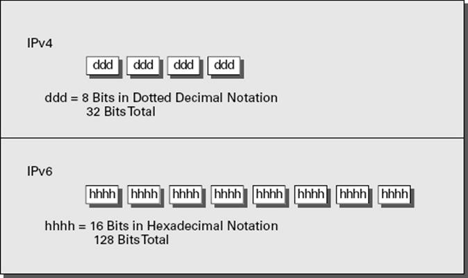
FIGURE 8.13 IPv4/IPv6 comparison
A full IPv6 address looks like this example:
1. 2001:0DB8:0000:0000:1234:0000:A9FE:133E
You can tell the implementation of DNS will make life a lot easier even for those who like to ping the address in lieu of the name. Fortunately, DNS already has the ability to handle IPv6 addresses with the use of an AAAA record. (A is short for alias.) An A record in IPv4’s addressing space is 32 bits, so an AAAA record, or four As, is 128 bits. The Windows Server 2012 R2 DNS server handles the AAAA and the reverse pointer (PTR) records for IPv6.
IPv6 Address Shortcuts
There are several shortcuts for writing an IPv6 address. These are described in the following list:
§ :0: stands for :0000:.
§ You can omit preceding 0s in any 16-bit word. For example, :DB8: and :0DB8: are equivalent.
§ :: is a variable standing for enough zeros to round out the address to 128 bits. :: can be used only once in an address.
You can use these shortcuts to represent the example address 2001:0DB8:0000:0000:1234:0000:A9FE:133E, as shown here:
§ Compress :0000: into :0::
2001:0DB8:0000:0000:1234:0:A9FE:133E
§ Eliminate preceding zeros:
2001:DB8:0000:0000:1234:0:A9FE:133E
§ Use the special variable shortcut for multiple 0s:
2001:DB8::1234:0:A9FE:133E
You now also use prefix notation or slash notation when discussing IPv6 networks. For example, the network of the previous address can be represented as 2001:DB8:0000:0000:0000:0000:0000:0000. This can also be expressed as 2001:DB8:: /32. The /32 indicates 32 bits of network, and 2001:DB8: is 32 bits of network.
IPv6 Address Assignment
So, do you subnet IPv6? The answer depends on your definition of subnetting. If you are given 32 bits of network from your ISP, you have 96 bits with which to work. If you use some of the 96 bits to route within your network infrastructure, then you are subnetting. In this context, you do subnet IPv6. However, given the huge number of bits you have available, you will no longer need to implement VLSM. For example, Microsoft has a network space of 2001:4898:: /32. That gives the administrators a space of 96 bits (296 = 79,228,162,514,264,337,593,543,950,336 unique addresses using all 96 bits) with which to work.
You can let Windows Server 2012 R2 dynamically/automatically assign its IPv6 address, or you can still assign it manually (see Figure 8.14). With dynamic/automatic assignment, the IPv6 address is assigned either by a DHCPv6 server or by the Windows Server 2012 R2 machine. If no DHCPv6 server is configured, the Windows Server 2012 R2 machine can query the local LAN segment to find a router with a configured IPv6 interface. If so, the server will assign itself an address on the same IPv6 network as the router interface and set its default gateway to the router interface’s IPv6 address. Figure 8.14 shows that you have the same dynamic and manual choices as you do in IPv4; however, the input values for IPv6 must conform to the new format.
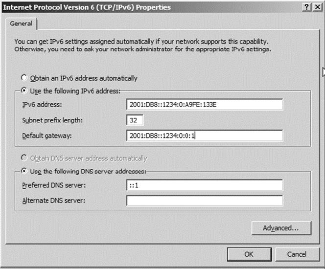
FIGURE 8.14 TCP/IPv6 Properties window
To see your configured IP addresses (IPv4 and IPv6), you can still use the ipconfig command. For example, I have configured a static IPv4 address and an IPv6 address on my server. The IPv6 address is the same as the one used in the earlier IPv6 example address.Figure 8.15 shows the result of this command on Windows Server 2012 R2 for my server.
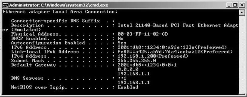
FIGURE 8.15 IPv6 configuration as seen from the command prompt
IPv6 Address Types
As stated earlier, there are three types of addresses in IPv6: anycast, unicast, and multicast. A description of each of these types of IPv6 addresses follows.
 Note the absence of the broadcast type, which is included in IPv4. You can’t use broadcasts in IPv6; they’ve been replaced with multicasts.
Anycast Addresses Anycast addresses are not really new. The concept of anycast existed in IPv4 but was not widely used. An anycast address is an IPv6 address assigned to multiple devices (usually different devices). When an anycast packet is sent, it is delivered to one of the devices, usually the closest one.
Unicast Addresses A unicast packet uniquely identifies an interface of an IPv6 device. The interface can be a virtual or pseudo-interface or a real (physical) interface.
Unicast addresses come in several types, as described in the following list:
1. Global Unicast Address As of this writing, the global unicast address space is defined as 2000:: /3. The 2001::/32 networks are the IPv6 addresses currently being issued to business entities. As mentioned, Microsoft has been allocated 2001:4898:: /32. A Microsoft DHCPv6 server would be set up with scopes (ranges of addresses to be assigned) within this address space. There are some special addresses and address formats that you will see in use as well. You’ll find most example addresses listed as 2001:DB8:: /32; this space has been reserved for documentation. Do you remember the loopback address in IPv4, 127.0.0.1? In IPv6 the loopback address is ::1 (or 0:0:0:0:0:0:0:0001). You may also see an address with dotted-decimal used. A dual-stack Windows Server 2012 machine may also show you FE80::5EFE:192.168.1.200. This address form is used in an integration/migration model of IPv6 (or if you just can’t leave the dotted-decimal era, I suppose).
2. Link-Local Address Link-local addresses are defined as FE80:: /10. If you refer to Figure 8.15 showing the ipconfig command, you will see the link-local IPv6 address as fe80::a425:ab9d:7da4:ccba. The last 8 bytes (64 bits) are random to ensure a highprobability of randomness for the link-local address. The link-local address is to be used on a single link (network segment) and should never be routed.
3. There is another form of the local-link IPv6 address called the Extended User Interface 64-bit (EUI-64) format. This is derived by using the MAC address of the physical interface and inserting an FFFE between the third and fourth bytes of the MAC. The first byte is also made 02 (this sets the universal/local or U/L bit to 1 as defined in IEEE 802 frame specification). Again looking at Figure 8.15, the EUI-64 address would take the physical (MAC) address 00-03-FF-11-02-CD and make the link-local IPv6 address FE80::0203:FFFF:FE11:02CD. (I’ve left the preceding zeros in the link-local IPv6 address to make it easier for you to pick out the MAC address with the FFFE inserted.)
4. AnonymousAddress Microsoft Server 2012 R2 uses the random address by default instead of EUI-64. The random value is called the AnonymousAddress in Microsoft Server 2012 R2. It can be modified to allow the use of EUI-64.
5. Unique Local Address The unique local address can be Fc00 or FD00, and it is used like the private address space of IPv4. RFC 4193 describes unique local addresses. They are not expected to be routable on the global Internet. They are used for private routing within an organization.
Multicast Address Multicast addresses are one-to-many communication packets. Multicast packets are identifiable by their first byte (most significant byte, leftmost byte, leftmost 2 nibbles, leftmost 8 bits, and so on). A multicast address is defined as FF00::/8.
In the second byte shown (the 00 of FF00), the second 0 is what’s called the scope. Interface-local is 01, and link-local is 02. FF01:: is an interface-local multicast.
There are several well-known (already defined) multicast addresses. For example, if you want to send a packet to all nodes in the link-local scope, you send the packet to FF02::1 (also shown as FF02:0:0:0:0:0:0:1). The all-routers multicast address is FF02::2.
You can also use multicasting to get the logical link layer address (MAC address) of a device with which you are trying to communicate. Instead of using the ARP mechanism of IPv4, IPv6 uses the ICMPv6 neighbor solicitation (NS) and neighbor advertisement (NA) messages. The NS and NA ICMPv6 messages are all part of the new Neighbor Discovery Protocol (NDP). This new ICMPv6 functionality also includes router solicitation and router advertisements as well as redirect messages (similar to the IPv4 redirect functionality).
Table 8.7 outlines the IPv6 address space known prefixes and some well-known addresses.
TABLE 8.7 IPv6 address space known prefixes and addresses
|
Address Prefix |
Scope of Use |
|
2000:: /3 |
Global unicast space prefix |
|
FE80:: /10 |
Link-local address prefix |
|
FC00:: /7 |
Unique local unicast prefix |
|
FD00:: /8 |
Unique local unicast prefix |
|
FF00:: /8 |
Multicast prefix |
|
2001:DB8:: /32 |
Global unicast prefix used for documentation |
|
::1 |
Reserved local loopback address |
|
2001:0000: /32 |
Teredo prefix (discussed later in this chapter) |
|
2002:: /16 |
6to4 prefix |
Unicast vs. Anycast
Unicast and anycast addresses look the same and may be indistinguishable from each other; it just depends on how many devices have the same address. If only one device has a globally unique IPv6 address, it’s a unicast address. If more than one device has the same address, it’s an anycast address. Both unicast and anycast are considered one-to-one communication, although you could say that anycast is one-to-“one of many.”
IPv6 Integration/Migration
It’s time to get into the mind-set of integrating IPv6 into your existing infrastructure with the longer goal of migrating to IPv6. In other words, this is not going to be an “OK, Friday the Internet is changing over” rollout. You have to bring about the change as a controlled implementation. It could easily take three to five years before a solid migration occurs and probably longer. I think the migration will take slightly less time than getting the world to migrate to the metric system on the overall timeline. The process of integration/migration consists of several mechanisms.
Dual Stack Simply running both IPv4 and IPv6 on the same network, utilizing the IPv4 address space for devices using only IPv4 addresses and utilizing the IPv6 address space for devices using IPv6 addresses
Tunneling Using an encapsulation scheme for transporting one address space inside another
Address Translation Using a higher-level application to change one address type (IPv4 or IPv6) to the other transparently so that end devices are unaware one address space is talking to another
I elaborate on these three mechanisms in the following sections.
IPv6 Dual Stack
The default implementation in Windows Server 2012 R2 is an enabled IPv6 configuration along with IPv4; this is dual stack. The implementation can be dual IP layer or dual TCP/IP stack. Windows Server 2012 R2 uses the dual IP layer implementation (see Figure 8.16). When an application queries a DNS server to resolve a hostname to an IP address, the DNS server may respond with an IPv4 address or an IPv6 address. If the DNS server responds with both, Windows Server 2012 R2 will prefer the IPv6 address. Windows Server 2012 R2 can use both IPv4 and IPv6 addresses as necessary for network communication. When looking at the output of the ipconfig command, you will see both address spaces displayed.
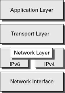
FIGURE 8.16 IPv6 dual IP layer diagram
IPv6 Tunneling
Windows Server 2012 R2 includes several tunneling mechanisms for tunneling IPv6 through the IPv4 address space. They include the following:
§ Intra-Site Automatic Tunnel Addressing Protocol (ISATAP), which is used for unicast IPv6 communication across an IPv4 infrastructure. ISATAP is enabled by default in Windows Server 2012 R2.
§ 6to4, which is used for unicast IPv6 communication across an IPv4 infrastructure.
§ Teredo, which is used for unicast IPv6 communication with an IPv4 NAT implementation across an IPv4 infrastructure.
With multiple tunneling protocols available and enabled by default, you might ask, what’s the difference, and why is one used over the others? They all allow you to tunnel IPv6 packets through the IPv4 address space (a really cool thing if you’re trying to integrate/migrate). Here are the details of these tunneling mechanisms:
ISATAP Intra-Site Automatic Tunnel Addressing Protocol (ISATAP) is the automatic tunnel addressing protocol providing IPv6 addresses based on the IPv4 address of the end interface (node). The IPv6 address is automatically configured on the local device, and the dual stack machine can use either its IPv4 or IPv6 address to communicate on the local network (within the local network infrastructure). ISATAP can use the neighbor discovery mechanism to determine the router ID and network prefix where the device is located, thus making intrasite communication possible even in a routed infrastructure.
The format of an ISATAP address is as follows:
1. [64bits of prefix] [32bits indicating ISATAP] [32bits IPv4 Address]
The center 32 bits indicating ISATAP are actually 0000:5EFE (when using private IPv4 addresses). The ISATAP address of the example Windows Server 2012 R2 machine using the link-local IPv6 address is FE80::5EFE:192.168.1.200. Each node participating in the ISATAP infrastructure must support ISATAP. If you’re routing through an IPv4 cloud, a border router (a router transitioning from an IPv6 to IPv4 space) must support ISATAP. Windows Server 2012 R2 can be configured as a border router, and it will forward ISATAP packets. ISATAP is experimental and is defined in RFC 4214.
6to4 6to4 specifies a procedure for IPv6 networks to communicate with each other through an IPv4 space without the IPv6 nodes having to know what’s happening. The IPv6 nodes do not need to be dual stacked to make this happen. The border router is the device responsible for knowing about the IPv6-to-IPv4 transition. The IPv6 packets are encapsulated at the border router (and decapsulated at the other end or on the way back). There is an assigned prefix for the 6to4 implementation: 2002:: /16. 6to4 is defined in RFC 3056.
Teredo Teredo (named after a kind of shipworm that drills holes in the wood of ships) is a protocol designed to allow IPv6 addresses to be available to hosts through one or more layers of NAT. Teredo uses a process of tunneling packets through the IPv4 space using UDP. The Teredo service encapsulates the IPv6 data within a UDP segment (packet) and uses IPv4 addressing to get through the IPv4 cloud. Having a layer 4 (Transport layer) available to use as translation functionality is what gives you the ability to be behind a NAT. Teredo provides host-to-host communication and dynamic addressing for IPv6 nodes (dual stack), allowing the nodes to have access to resources in an IPv6 network and the IPv6 devices to have access to the IPv6 devices that have only connectivity to the IPv4 space (like home users who have an IPv6-enabled operating system connecting to IPv6 resources while their home ISP has only IPv4 capabilities). Teredo is defined in RFC 4380.
In Windows Server 2012 R2, an IPv4 Teredo server is identified and configured (using the netsh command interface). The Teredo server provides connectivity resources (address) to the Teredo client (the node that has access to the IPv4 Internet and needs access to an IPv6 network/Internet). A Teredo relay is a component used by the IPv6 router to receive traffic destined for Teredo clients and forward the traffic appropriately. The defined prefix for Teredo address is 2001:0000:: /32. Teredo does add overhead like all the other implementations discussed. It is generally accepted that you should use the simplest model available. However, in the process of integration/migration for most of us behind a NAT, Teredo will be the process to choose.
From Windows Server 2012 R2, use the ipconfig /all command to view the default configurations including IPv4 and IPv6. You may notice a notation that I didn’t discuss, the percent sign at the end of the IPv6 address (see Figure 8.17). The number after the percent sign is the virtual interface identifier used by Windows Server 2012 R2.
![]()
FIGURE 8.17 IPv6 interface identifier for ipconfig display
Useful IPv6 Information Commands
You can use numerous commands to view, verify, and configure the network parameters of Windows Server 2012 R2. Specifically, you can use the netsh command set and the route command set as well as the standard ping and tracert functions.
Use the netsh command interface (as well as the provided dialog boxes, if you want) to examine and configure IPv6 functionality. The netsh command issued from the command interpreter changes into a network shell (netsh) where you can configure and view both IPv4 and IPv6 components.
Don’t forget to use the ever-popular route print command to see the Windows Server 2012 R2 routing tables (IPv4 and IPv6). The other diagnostic commands are still available for IPv4 as well as IPv6. In previous versions of Microsoft operating systems, ping was the IPv4 command, and ping6 was the IPv6 command. This has changed in Windows Server 2012 R2; ping works for both IPv4 and IPv6 to test layer 3 connectivity to remote devices. The IPv4 tracert command was tracert6 for IPv6. The command is now tracert for both IPv4 and IPv6, and it will show you every layer 3 (IP) hop from source to destination. (This assumes that all of the administrators from here to there want you to see the hops and are not blocking ICMP. It also assumes that there are no IP tunnels, which your packets are traversing; you won’t see the router hops in the tunnel either.)
Overall, the consortium of people developing the Internet and the Internet Protocol have tried to make all of the changes to communication infrastructures easy to implement. (This is a daunting task with the many vendors and various infrastructures currently in place.) The goal is not to daze and confuse administrators; it’s designed to provide maximum flexibility with the greatest functionality. IPv6 is going to provide the needed layer 3 (Network layer, global addressing layer, logical addressing layer...call it what you like) functionality for the foreseeable future.
Subnetting with IPv6
Subnetting with IPv6 is a lot like subnetting with IPv4. You need to know how many bits you are going to use for the network mask to subnet it correctly.
For example, let’s say you have an IPv6 prefix of 2001:DB8:BBCC:0000::/53 and you need to set up your network so that your IPv6 addressing scheme can handle 1,500 more subnets. How would you figure this out?
When determining any number of hosts or subnets, the calculation is 2 to the power (2x). The first power number that is greater than or equal to the number you need is the power number that you add to the current network mask. Thus, in the previous question, to get to 1,500 subnets, you would need to determine which 2x is the first one that is greater than or equal to 1,500. If you calculate your powers correctly, 211 (211 = 2,048) is the first one that is greater than or equal to 1,500. So, you would add the power of 11 to the /53 in the previous address, and you would now use /64 as your network mask. Table 8.8 shows you some of the power numbers for the power of 2.
TABLE 8.8 Powers of 2
|
Power |
Equals |
|
22 |
4 |
|
23 |
8 |
|
24 |
16 |
|
25 |
32 |
|
26 |
64 |
|
27 |
128 |
|
28 |
256 |
|
29 |
512 |
|
210 |
1024 |
|
211 |
2048 |
|
212 |
4096 |
Summary
Why TCP/IP is the primary protocol in use today is one of the important topics covered in this chapter. You also learned that the 32-bit IPv4 address is a structured and hierarchical one that is used to identify uniquely every machine on a network. You learned how to determine available IP addresses and implement subnetting. In addition, you learned how the new layer 3 IPv6 protocol is implemented, including the structure of the IPv6 address. Finally, I discussed the new functionality included in IPv6 addressing as well as several Windows Server 2012 R2 integration/migration implementations.
Exam Essentials
Understand what subnetting is and when to use it. If an organization is large and has many computers or if its computers are geographically dispersed, it’s sensible to divide its large network into smaller ones connected by routers. These smaller networks are called subnets. Subnetting is the process of carving a single IP network into smaller, logical subnetworks.
Understand subnet masks. For the subnet address scheme to work, every machine on the network must know which part of the host address will be used as the subnet address. The network administrator creates a 32-bit subnet mask consisting of 1s and 0s. The 1s in the subnet mask represent the positions that refer to the network or subnet addresses. The 0s represent the positions that refer to the host portion of the address.
Understand IPv6. Understand the structure of an IPv6 address and how it’s displayed. Know the shortcuts and rules (such as for displaying 0s) for writing IPv6 addresses. Know the integration/migration components for IPv6 included in Windows Server 2012 R2, including tunneling and dual stack.
Review Questions
1. You are the network administrator for ABC Company. You have an IPv6 prefix of 2001:DB8:BBCC:0000::/53, and you need to set up your network so that your IPv6 addressing scheme can handle 1,000 more subnets. Which network mask would you use?
A. /60
B. /61
C. /62
D. /63
E. /64
2. You are the network administrator for Stellacon Corporation. Stellacon has a Windows Server 2012 R2 machine that needs to be able to communicate with all of the computers on the internal network. Stellacon has decided to add 15 new segments to its IPv6 network. How would you configure the IPv6 address so that the server can communicate with all the segments?
A. Configure the IPv6 address as fd00::2b0:e0ff:dee9:4143/8.
B. Configure the IPv6 address as fe80::2b0:e0ff:dee9:4143/32.
C. Configure the IPv6 address as ff80::2b0:e0ff:dee9:4143/64.
D. Configure the IPv6 address as fe80::2b0:e0ff:dee9:4143/64.
3. You are the network administrator for a midsize organization that has installed Windows Server 2012 R2 onto the network. You are thinking of moving all machines to Windows 8 and IPv6. You decide to set up a test environment with four subnets. What type of IPv6 addresses do you need set up?
A. Global addresses
B. Link-local addresses
C. Unique local addresses
D. Site-local addresses
4. You have a large IP-routed network using the address 137.25.0.0; it is composed of 20 subnets, with a maximum of 300 hosts on each subnet. Your company continues on a merger-and-acquisitions spree, and your manager has told you to prepare for an increase to 50 subnets with some containing more than 600 hosts. Using the existing network address, which of the following subnet masks would work for the requirement set by your manager?
A. 255.255.252.0
B. 255.255.254.0
C. 255.255.248.0
D. 255.255.240.0
5. Your company is growing dramatically via acquisitions of other companies. As the network administrator, you need to keep up with the changes because they affect the workstations, and you need to support them. When you started, there were 15 locations connected via routers, and now there are 25. As new companies are acquired, they are migrated to Windows Server 2012 R2 and brought into the same domain as another site. Management says that they are going to acquire at least 10 more companies in the next two years. The engineers have also told you that they are redesigning the company’s Class B address into an IP addressing scheme that will support these requirements and that there will never be more than 1,000 network devices on any subnet. What is the appropriate subnet mask to support this network when the changes are completed?
A. 255.255.252.0
B. 255.255.248.0
C. 255.255.255.0
D. 255.255.255.128
6. You work for a small printing company that has 75 workstations. Most of them run standard office applications such as word processing, spreadsheet, and accounting programs. Fifteen of the workstations are constantly processing huge graphics files and then sending print jobs to industrial-sized laser printers. The performance of the network has always been an issue, but you have never addressed it. You have now migrated your network to Windows 8 and Windows Server 2012 R2 and have decided to take advantage of the routing capability built into Windows Server 2012 R2. You choose the appropriate server and place two NICs in the machine, but you realize that you have only one network address, 201.102.34.0, which you obtained years ago. How should you subnet this address to segment the bandwidth hogs from the rest of the network while giving everyone access to the entire network?
A. 255.255.255.192
B. 255.255.255.224
C. 255.255.255.252
D. 255.255.255.240
7. You work for Carpathian Worldwide Enterprises, which has more than 50 administrative and manufacturing locations around the world. The size of these organizations varies greatly, with the number of computers per location ranging from 15 to slightly fewer than 1,000. The sales operations use more than 1,000 facilities, each of which contains 2 to 5 computers. Carpathian is also in merger talks with another large organization. If the merger materializes as planned, you will have to accommodate another 100 manufacturing and administrative locations, each with a maximum of 600 computers, as well as 2,000 additional sales facilities. You don’t have any numbers for the future growth of the company, but you are told to keep growth in mind. You decide to implement a private addressing plan for the entire organization. More than half of your routers don’t support variable-length subnet masking. Which subnet masks would work for this situation? (Choose all that apply.)
A. 255.255.224.0
B. 255.255.240.0
C. 255.255.248.0
D. 255.255.252.0
E. 255.255.254.0
8. Which of the following subnet masks are represented with the CIDR of /27?
A. 255.255.255.254
B. 255.255.255.248
C. 255.255.255.224
D. 255.255.255.240
9. You are the administrator for a Windows Server 2012 R2 network that uses DHCP. You notice that your DHCP database is getting too large, and you want to reduce the size of the database. What should you do?
A. From the folder containing the DHCP database, run jetpack.exe dhcp.mdb temp.mdb.
B. From the folder containing the DHCP database, run shrinkpack.exe dhcp.mdb temp.mdb.
C. From the folder containing the DHCP database, run jetshrink.exe dhcp.mdb temp.mdb.
D. From the folder containing the DHCP database, run shrinkjet.exe dhcp.mdb temp.mdb.
10. You ask one of your technicians to get the IPv6 address of a new Windows Server 2012 R2 machine, and she hands you a note with FE80::0203:FFFF:FE11:2CD on it. What can you tell from this address? (Choose two.)
A. This is a globally unique IPv6 address.
B. This is a link-local IPv6 address.
C. This is a multicast IPv6 address.
D. In EUI-64 format, you can see the MAC address of the node.
E. In EUI-64 format, you can see the IPv4 address of the node.
All materials on the site are licensed Creative Commons Attribution-Sharealike 3.0 Unported CC BY-SA 3.0 & GNU Free Documentation License (GFDL)
If you are the copyright holder of any material contained on our site and intend to remove it, please contact our site administrator for approval.
© 2016-2026 All site design rights belong to S.Y.A.