Windows 8.1 Administration Pocket Consultant: Storage, Security, & Networking (2014)
Chapter 1. Managing Firmware, Boot Configuration, and Startup
§ Navigating and understanding firmware options
§ Navigating startup and power states
§ Diagnosing and resolving startup problems
§ Managing startup and boot configuration
§ Managing the BCD store
As surprising as it might seem, when a computer fails to start or experiences a Stop error that crashes the operating system, the most basic element involved in starting a computer and loading an operating system—the firmware—is often overlooked as a possible cause. This happens because most people dig in and begin troubleshooting Windows without looking at the firmware. The trouble with this approach is that many computer problems originate in firmware, either because the firmware itself is flawed or because the firmware has been improperly configured. To distinguish between problems in firmware and problems in the operating system, you need to understand how the startup process works and what occurs during each of its phases. You also need to understand firmware itself. Primed with a solid understanding of these subjects, you’ll be better prepared to diagnose and resolve related problems.
Navigating and understanding firmware options
The startup process involves firmware, firmware interfaces, and an operating system. During startup, firmware is the first code that runs. Firmware performs basic initialization of the computer and provides the services that enable a computer to start loading an operating system.
Platform firmware is implemented in motherboards and chipsets. All computers—whether tablets, desktops, or laptops—have motherboard chipsets, and there are many different types. Although older motherboard chipsets might not be updatable, most newer ones have updatable firmware. Chipset firmware is separate and different from the computer’s underlying firmware interface.
Windows for the ARM processor architecture, also called Windows On ARM (or WOA), is designed with platform firmware that is also implemented in a motherboard chipset. With WOA, though, the board is a series of silicon layers packaged together in a very small form factor called aSystem on a Chip (SoC). At the time of this writing, there are two variants of Windows On ARM: Windows RT, which was originally designed for tablets, and Windows Phone operating system, which was originally designed for smartphones. Though Windows RT has nearly the same UI as Windows 8.1, the Windows Phone operating system has a UI that has substantial differences from Windows 8.1.
NOTE
WOA presents a special case for firmware, boot configuration, and startup. Although I’ve tried to integrate some WOA discussion into this chapter, not everything I discuss in this chapter will apply to WOA. Further, it is important to point out that I refer to WOA throughout this chapter rather than discussing either Windows RT or Windows Phone operating system specifically. In the future, Windows Phone operating system might be merged into Windows RT (or a new variant might be created by merging aspects of both).
Firmware interface types and boot data
Every computer has firmware, yet it’s the interface between that firmware and the operating system that handles the startup process. The way a firmware interface works and the tasks it performs depend on the type of firmware interface. Currently, the prevalent firmware interfaces are:
§ Basic input/output system (BIOS)
§ Extensible Firmware Interface (EFI)
§ Unified Extensible Firmware Interface (UEFI)
A computer’s BIOS, EFI, or UEFI provides the hardware-level interface between hardware components and software. Like chipsets themselves, BIOS, EFI, and UEFI can be updated. Most technical documentation refers to a computer’s firmware interface simply as firmware. For example, documentation might specify to make “such and such a change in firmware” or to “check firmware.” Technically, you make the change in the firmware interface, and the firmware interface makes the change in firmware.
UEFI is both a type of firmware interface and an industry standard. UEFI, as a firmware interface, is modular and does not necessarily serve the same purpose or provide the same functionality as BIOS or EFI. UEFI, as a standard, is designed to provide extensible and testable interfaces. For WOA, UEFI is the lowest layer of the system and, as with other chip architectures, UEFI provides the services necessary to load the operating system. WOA also supports Trusted Platform Module (TPM) for trusted boot and hardware-based drive encryption.
It’s also important to understand that BIOS, EFI, and UEFI work in distinctly different ways. BIOS is based on x86, 16-bit, real-mode architecture and was originally designed to get a computer started after the computer was powered on. This is why BIOS performs firmware-to-operating-system interfacing and platform initialization.
Regardless of the firmware interface type, Windows 8.1 uses a pre–operating system boot environment. The boot environment is an extensible abstraction layer that makes it possible for the operating system to work with multiple types of firmware interfaces without requiring the operating system to be specifically written to work with these firmware interfaces. Within the boot environment, startup is controlled by using the parameters in the Boot Configuration Data (BCD) store.
All computers running current Windows operating systems have a BCD store. The BCD store is contained in a file called the BCD registry. The location of this registry depends on the computer’s firmware, as follows:
§ On BIOS-based operating systems, the BCD registry file is stored in the \Boot\Bcd directory of the active partition.
§ On EFI-based operating systems, the BCD registry file is stored on the EFI system partition.
Entries in the BCD store identify the boot manager to use during startup and the specific boot applications available. The default boot manager is Windows Boot Manager. Windows Boot Manager controls the boot experience and enables you to choose which boot application is to run. Boot applications load a specific operating system or operating system version. For example, the boot application for Windows 8.1 is the Windows Boot Loader, which enables you to boot BIOS-based and EFI-based computers in much the same way.
Typically, you can press F8 or F12 during startup of the operating system to access the Advanced Boot Options menu, and then use this menu to select one of several advanced startup modes, including Safe Mode, Enable Boot Logging, and Disable Driver Signature Enforcement. These advanced modes temporarily modify the way the operating system starts to help you diagnose and resolve problems; however, they don’t make permanent changes to the boot configuration or to the BCD store.
Boot services, run-time services, and beyond
BIOS manages the preboot data flow between the operating system and attached devices, such as the video adapter, keyboard, mouse, and hard drive. When BIOS initializes a computer, it first determines whether all attached devices are available and functioning, and then it begins to load the operating system.
Over the years, these basic features of BIOS were expanded to encompass the following:
§ Boot services Refers to the collection of interfaces and protocols that are present in the boot environment. The services at a minimum provide an operating system loader with access to platform capabilities required to complete the operating system boot. These services are also available to drivers and applications that need access to platform capabilities. Boot services are terminated after the operating system takes control of the computer.
§ Run-time services Refers to the interfaces that provide access to underlying platform-specific hardware, such as timers, that might be useful during operating system run time. These services are available during the boot process but also persist after the operating system loader terminates boot services.
§ Advanced Configuration and Power Interface (ACPI) Refers to a table-based interface to the system board that enables the operating system to implement operating system–directed power management and system configuration.
§ Services for system management BIOS (SMBIOS) Refers to a table-based interface that is required by the Wired for Management Baseline (WMB) specification and used to relate platform-specific management information to the operating system or to an operating system–based management agent.
Generally, computers with BIOS use hard drives that have master boot record (MBR) partitions. To break free of the 16-bit roots of BIOS, Intel developed EFI as a firmware implementation for its 64-bit Itanium-based processors. EFI is based on x64, 64-bit, real-mode architecture. As with BIOS, EFI performs firmware-to-operating-system interfacing, platform initialization, and other functions. With the introduction of EFI, Intel also provided a new table architecture for hard drives, called the GUID partition table (GPT).
MBR is now considered a legacy partitioning scheme, with GPT as the preferred partitioning scheme. A legacy MBR is located at the first logical block on a disk that is not using the GPT disk layout. The first 512 bytes on an MBR disk have the following layout:
§ The MBR begins with a 424-byte boot code, which is used to select an MBR partition record and load the first logical block of that partition. The boot code on the MBR is not executed by UEFI.
§ The boot code is followed by a 4-byte unique MBR disk signature, which can be used by the operating system to identify the disk and distinguish the disk from other disks on the system. The unique signature is written by the operating system and not used by UEFI.
§ A 2-byte separator follows the disk signature. At byte offset 446, there is an array of four MBR partition records, with each record being 16 bytes in length. Block 510 contains 0x55 and block 511 contains 0xAA. Block 512 is reserved.
The four partition records each define the first and last logical blocks that a particular partition uses on a disk:
§ Each 16-byte MBR partition record begins with a 1-byte boot indicator. For example, a value of 0x80 identifies a bootable legacy partition. Any other value indicates that this is not a bootable legacy partition. This value is not used by UEFI.
§ The boot indicator is followed by a 3-byte address identifying the start of the partition. At byte offset 4, there’s a 1-byte value that indicates the operating system type, which is followed by a 3-byte value that identifies the end of the partition. These values are not used by UEFI.
§ At byte offset 8, there’s a 4-byte value indicating the first logical block of the partition, and this is followed by a 4-byte value indicating the size of the partition in units of logical blocks. Both of these values are used by UEFI.
NOTE
If an MBR partition has an operating system type value of 0xEF, firmware must add the UEFI system partition GUID to the handle for the MBR partition. This enables boot applications, operating system loaders, drivers, and other lower-level tools to locate the UEFI system partition, which must physically reside on the disk.
A protective MBR may be located at the first logical block on a disk that is using the GPT disk layout. The protective MBR precedes the GUID Partition Table header and is used to maintain compatibility with tools that do not understand GPT partition structures. The purpose of the protective MBR is to protect the GPT partitions from boot applications, operating system loaders, drivers, and other lower-level tools that don’t understand the GPT partitioning scheme. The protective MBR does this by defining a fake partition covering the entire disk. When a disk has a protective MBR, the first 512 bytes on the disk have the following layout:
§ The protective MBR begins with a 424-byte boot code, which is not executed by UEFI.
§ The boot code is followed by a 4-byte disk signature, which is set to zero and not used by UEFI.
§ A 2-byte separator follows the disk signature. This separator is set to zero and not used by UEFI.
§ At byte offset 446, there is an array of four MBR partition records, with each record being 16 bytes in length. Only the first partition record—the protective partition record—is used. The other partition records are set to zero.
§ Block 510 contains 0x55, and block 511 contains 0xAA. Block 512 is reserved.
The protective partition record reserves the entire space on the disk after the first 512 bytes for the GPT disk layout. The protective partition record begins with a 1-byte boot indicator that is set to 0x00, which indicates a non-bootable partition. The boot indicator is followed by a 3-byte address identifying the start of the partition at 0x000200, which is the first usable block on the disk.
At byte offset 4, there’s a 1-byte value set to 0xEE to indicate the operating system type as GPT Protective. This is followed by a 3-byte value that identifies the last usable block on the disk, which is the end of the partition (or 0xFFFFFF if it is not possible to represent this value).
At byte offset 8, there is a 4-byte value set to 0x00000001, which identifies the logical block address of the GPT partition header. This is followed by a 4-byte value indicating size of the disk minus one block (or 0xFFFFFFFF if the size of the disk is too large to be represented).
UEFI
As Intel began developing EFI, Intel developers and others around the world began to recognize the need to break the tie between firmware and processor architecture. This led to the development of UEFI. The UEFI 2.4 specification was finalized in April 2013. The UEFI specifications define a model for the interface between operating systems and platform firmware. The interface consists of data tables that contain platform-related information, in addition to boot and run-time service calls that are available to the operating system and its loader. The interface is independent of the processor architecture. Because UEFI abstracts the processor architecture, UEFI works with computers that have x86, x64, ARM, or an alternative architecture. As with EFI, computers with UEFI generally use hard drives that have GPT partitions. However, UEFI doesn’t replace all the functionality in either BIOS or EFI and can, in fact, be wrapped around BIOS or EFI.
NOTE
REAL WORLD UEFI 2.4 is an incremental enhancement of UEFI 2.31, which was released in April 2011. UEFI 2.4 adds support for NIC iSCSI and FCoE boot capabilities and current boot mode. UEFI 2.4 also has improvements to prevent conflicts with Secure Boot and enables hashes of certificates to be used for revocation and timestamp support. Secure boot and other advanced security features are discussed in Chapter 2.
In UEFI, the system abstraction layer (SAL) is the firmware that abstracts platform implementation differences and provides the basic interface to all higher-level software. UEFI defines boot services and run-time services.
UEFI boot services include:
§ Event, timer, and task priority services that create, wait for, signal, check, and close events; set timers; and raise or restore the priority of tasks.
§ Memory allocation services that allocate or free memory pages, get memory maps, and allocate or free pooled memory.
§ Driver model boot services that handle protocol interfaces for devices, open and close protocol streams, and connect or disconnect from controllers.
§ Image services that load, start, and unload images.
§ Miscellaneous services that set watchdog timers, copy and set memory, install configuration tables, and perform cyclic redundancy checking (CRC) calculations.
UEFI run-time services include:
§ Variable services that get, set, and query variables.
§ Time services that get and set time and get and set wakeup time.
§ Virtual memory services that set virtual address mapping and convert memory pointers.
§ Miscellaneous services that reset the computer, return counters, and pass information to the firmware.
UEFI defines architecture-independent models for EFI-loaded images, device paths, device drivers, driver signing, and secure boot. It also defines the following:
§ Console support, which enables simple text and graphics output.
§ Human Interface Infrastructure support, which describes the basic mechanisms for managing user input and provides definitions for related protocols, functions, and type definitions that can help abstract user input.
§ Media support, which enables I/O access to file systems, files, and media devices.
§ Peripheral Component Interconnect (PCI), small computer system interface (SCSI), and Internet small computer system interface (iSCSI) bus support, which enables I/O access across a PCI, SCSI, or iSCSI bus, in addition to SCSI or iSCSI boot.
§ USB support, which enables I/O access over USB host controllers, USB buses, and USB devices.
§ Compression support, which provides algorithms for compressing and decompressing data.
§ ACPI table support, which enables installation or removal of an ACPI table.
§ EFI byte code virtual machine support, which enables loading and executing EFI device drivers.
§ Network protocol support, which defines the Simple Network Protocol (SNP), Preboot Execution Environment (PXE), and Boot Integrity Services (BIS) protocols. SNP provides a packet-level interface to network adapters. PXE is used for network access and network booting. BIS is used to check the digital signature of a data block against a digital certificate for the purpose of checking integrity and authorization. PXE uses BIS to check downloaded network boot images before executing them.
§ Managed network protocol support, which defines the Managed Network Service Binding Protocol (MNSBP) and the Managed Network Protocol (MNP). These services enable multiple event-driven drivers and applications to access and use network interfaces simultaneously. MNSBP is used to locate communication devices that are supported by an MNP drive and manage instances of protocol drivers. MNP is used by drivers and applications to perform raw asynchronous network-packet I/O.
§ Network addressing protocol support, which defines the following protocols: Address Resolution Protocol Service Binding Protocol (ARPSBP), Address Resolution Protocol (ARP), DHCPv4, DHCPv4 service binding, DHCPv6, and DHCPv6 service binding.
§ Miscellaneous network protocol support, which defines the following protocols: virtual LAN configuration, EAP and EAP management, TCPv4, TCPv4 service binding, TCPv6, TCPv6 service binding, IPv4, IPv4 service binding and configuration, IPv6, IPv6 service binding and configuration, IPSec and IPSec2 configuration, FTPv4, FTPv4 service binding, UDPv4, UDPv4 service binding, UDPv6, UDPv6 service binding, Multicast TFTPv4, and Multicast TFTPv6.
NOTE
With WOA, ACPI is used for plug and play enumeration of devices (such as touch controllers, displays, and so on) during boot and for power management of devices outside of the SoC. Otherwise, there is no device tree or ability to discover what is connected to a SoC or determine how the SoC is connected.
To be clear, UEFI is not designed to replace either BIOS or EFI. Although UEFI uses a different interface for boot services and run-time services, some platform firmware must perform the functions that BIOS and EFI need for system configuration and setup because UEFI does not do this. For this reason, UEFI is often implemented on top of traditional BIOS and EFI, in which case UEFI takes the place of the initialization entry points into BIOS or EFI.
Navigating startup and power states
When a computer is first started, the firmware interface activates all the hardware required by the computer to initialize and load the operating system, including:
§ Motherboard chipsets
§ Processors and processor caches
§ System memory
§ Graphics and audio controllers
§ Internal drives
§ Internal expansion cards
After the firmware interface completes this process, it transfers control of the computer to the operating system. The firmware interface implementation determines what happens next:
§ With BIOS-based computers running current Windows operating systems, Windows Boot Manager and Windows Boot Loader are used to boot into the operating system. Windows Boot Manager initializes the operating system by starting the Windows Boot Loader, which in turn starts the operating system by using information in the BCD store. Through the BCD parameters, you can add options that control the way the operating system starts, the way computer components are used, and the way operating system features are used.
§ With Itanium-based computers, Ia64ldr.efi, Diskpart.efi, and Nvrboot.efi are used to boot into the operating system. Ia64ldr.efi handles the task of loading the operating system, whereas Diskpart.efi identifies the boot partitions. Through Nvrboot.efi, you set the parameters that enable startup.
§ With other EFI-based computers, Bootmgfw.efi manages the boot process and passes control to the Windows Boot Loader. Through Bcdedit.exe, you set the parameters that enable startup.
§ With UEFI, UEFI boot services provide an abstraction layer. Currently, this abstraction layer is wrapped around BIOS or EFI. A computer with BIOS in its underlying architecture uses a BIOS-based approach to booting into the operating system. A computer with EFI in its underlying architecture uses an EFI-based approach to booting into the operating system.
§ With WOA, UEFI boot services provide an abstraction layer. Windows Boot Manager initializes the operating system by starting the Windows Boot Loader, which in turn starts the operating system by using information in the BCD store. Information needed to configure the device is stored in tables.
Working with firmware interfaces
When you power on most computers, you can access the firmware interface by pressing the key designated for Setup in the initial display. For example, you might press F2 or Delete during the first few seconds of startup to enter the firmware interface. Firmware interfaces have control options that make it possible for you to adjust the functionality of hardware. You can use these controls to do the following:
§ Adjust LCD brightness (on laptop computers).
§ Adjust the hard drive noise level.
§ Adjust the number of cores the processor is using and their speed.
§ Change the boot sequence.
§ Change the complementary metal oxide semiconductor (CMOS) date and time.
§ Restore the firmware interface to the default configuration.
§ Turn on or off modular add-on devices.
Firmware interfaces have the ability to report basic configuration details, including information about the following:
§ AC adapter capacity (on laptop computers)
§ Battery charge and health (on laptop computers)
§ LCD type and native resolution (on laptop computers)
§ Firmware version
§ Memory
§ Processors
§ Storage devices
§ Video chipsets
Most firmware interfaces allow you to create supervisor, user, and/or general passwords that are not accessible from the operating system. If a supervisor password is set, you need to provide the password before you can modify the firmware configuration. If a user password is set, you need to enter the password during startup before the computer will load the operating system. If you forget these passwords, you might not be able to operate the computer or change firmware settings until you clear the forgotten passwords, which generally also clears any customization you have made to the firmware interface.
A firmware interface update can often resolve problems or add features to the computer’s firmware interface. If you are not experiencing problems on a computer and are not aware of any additional features in the firmware interface that are needed, you might not need to update a computer to the latest version of the firmware interface. An additional cautionary note is that if a firmware interface update is not performed properly, it can harm the computer and prevent it from starting.
Examining firmware interfaces
The information and configuration options available in the firmware interface depend on the computer with which you are working, the type of firmware interface, and the version of the firmware interface. Most desktop computers have more configuration options than do laptop computers.
As configured on my laptop computer, the firmware interface provides several menu pages offering information and controls, including Main, Advanced, Security, and Boot. The Main page provides basic information about the computer’s configuration, including:
§ System time and date.
§ System memory size.
§ Extended memory size.
§ Memory speed, such as 1,333 MHz.
§ CPU type, such as Intel Core i5-2430.
§ CPU speed, such as 2.40 GHz.
§ CPU cache levels for L1 cache, L2 cache, and L3 cache.
§ Hard drive type and model, such as WDC WD5000BPVT-75HXZ 500 GB.
§ Optical disk type and model, such as PLDS DVD +/- RW DU 8A-(S1) ATAPI.
§ System BIOS version, such as A02.
§ AC adapter type, such as 65 W.
§ Serial tag number.
§ Asset tag number.
§ Product name.
On the Main page, you can set the system date and time by using the options provided. The Advanced page provides additional configuration information and enables you to manage important settings. On the Advanced page, you can view or set the following:
§ Intel Multiple Monitor status as Enabled or Disabled. When this setting is enabled, the computer’s integrated graphic card and add-in graphic card might be able to work together in the operating system. When it is disabled, only one graphic card (either the integrated card or a plug-in card) can be used in the operating system.
§ Intel SpeedStep status as Enabled or Disabled. When this setting is enabled, the CPU can operate in multiple performance states. When it is disabled, the computer is prevented from adjusting the processor’s performance.
§ Intel Virtualization status as Enabled or Disabled. When this setting is enabled, a virtual machine monitor can use hardware virtualization capabilities.
§ Intel Turbo Boost status as Enabled or Disabled. When this setting is enabled, processor cores can run faster than the base operating frequency if they’re operating below temperature, current, and power limits.
§ USB PowerShare status as Enabled or Disabled. When this setting is enabled, users can use the USB PowerShare port to charge external devices by using the stored system battery power even if the computer is turned off.
§ USB Emulation status as Enabled or Disabled. When this setting is enabled, firmware can handle USB devices during the POST process (which occurs before the operating system starts).
§ USB Wake Support status as Enabled or Disabled. When this setting is enabled, USB devices can wake the computer.
The Security page enables you to view and set supervisor, user, and hard drive passwords. The status information tells you the current state for each password, such as:
§ Supervisor Password Is: Clear
§ User Password Is: Clear
§ Hard Disk Password Status: Clear
The following additional configuration options enable you to manage passwords:
§ Set Supervisor Password Controls access to the firmware interface
§ Set User Password Controls access to the computer
§ Set Hard Disk Password Controls access to the computer’s hard drive
To set a password, select the option, and then press Enter. When prompted, type the new password, and then type the new password again to confirm it. Press Enter to continue.
On the Boot page, the Boot Priority Order enables you to view and manage the priority order for boot devices. A sample boot priority order listing from a Dell desktop computer is as follows:
1. Hard drive
2. USB hard drive
3. CD/DVD
4. USB CD/DVD
5. USB Floppy
6. Network
When you power on the computer, the computer tries to boot using the device listed first. If that fails, the computer tries the second device, and so on. You can use the Up Arrow and Down Arrow keys to select a device, and then use the plus sign (+) or the hyphen (-) to move the device up or down in the list.
The Exit page enables you to exit the firmware interface and resume startup of the computer. As with most firmware interfaces, you have a few options:
§ Exit Saving Changes Exits the firmware interface and saves your changes
§ Exit Discarding Changes Exits the firmware interface and discards your changes
§ Discard Changes Discards your changes without exiting the firmware interface
§ Save Changes Saves your changes without exiting the firmware interface
Regardless of the menu page with which you are working, you have a set of options that are standard in most firmware interfaces:
§ Press F1 to get help.
§ Press the Up Arrow or Down Arrow key to select an item.
§ Press Enter to select the current option on a submenu.
§ Press the Left Arrow or Right Arrow key to select a menu page.
§ Press + or - to change values.
§ Press F9 to apply setup defaults (you must confirm when prompted).
§ Press Esc to exit (and then select an option to save or discard changes).
§ Press Enter to apply or execute a command.
§ Press F10 to save changes and exit the firmware interface. (When prompted to confirm, Yes is selected. Press Enter to save changes and exit. Press the spacebar to select No, and then press Enter to remain in the firmware interface.)
As you can tell, the configuration options here aren’t very extensive. In contrast, desktop computers can have a dizzying array of options and suboptions. When you are working with a desktop computer, you’ll likely find options that serve similar purposes. However, because few standards and conventions exist among firmware interface manufacturers, the options might have different labels and values.
Power states and power management
To better understand the hardware aspects related to boot issues, let’s dig in and take a look at ACPI. A computer’s motherboard chipset, firmware, and operating system must support ACPI for the related advanced power state features to work. ACPI-aware components track the power state of the computer. An ACPI-aware operating system can generate a request that the system be switched into a different ACPI mode, and the firmware interface responds by enabling the requested ACPI mode.
As shown in Table 1-1, there are six different power states, ranging from S0 (the system is completely on and fully operational) to S5 (the system is completely off). The states S1, S2, S3, and S4 are referred to as sleep states, in which the system appears off because of low power consumption but retains enough of the hardware context to return to the working state without a system reboot.
Motherboard chipsets support specific power states. For example, one motherboard might support the S0, S1, S4, and S5 states but not the S2 and S3 states. In Windows operating systems, the sleep power transition refers to switching off the system to a sleep or a hibernate mode, and thewake power transition refers to switching on the system from a sleep or a hibernate mode. The sleep and hibernate modes enable users to switch systems off and on much faster than the regular shutdown and startup processes.
Thus, a computer is waking up when the computer is transitioning from the Off state (S5) or any sleep state (S1–S4) to the On state (S0). The computer is turning off (going to sleep) when the computer is transitioning from the On state (S0) to the Off state (S5) or one of the sleep states (S1–S4). A computer cannot enter one sleep state directly from another; it must enter the On state before entering a different sleep state.
Table 1-1. Power states for ACPI in firmware and hardware
|
STATE |
TYPE |
DESCRIPTION |
|
S0 |
On state |
The system is completely operational, fully powered, and completely retains the context (such as the volatile registers, memory caches, and RAM). |
|
S1 |
Sleep state |
The system consumes less power than the S0 state. All hardware and processor contexts are maintained. |
|
S2 |
Sleep state |
The system consumes less power than the S1 state. The processor loses power, and processor context and contents of the cache are lost. |
|
S3 |
Sleep state |
The system consumes less power than the S2 state. Processor and hardware contexts, cache contents, and chipset context are lost. The system memory is retained. |
|
S4 |
Hibernate state |
The system consumes the least power compared to all other sleep states. The system is almost at the Off state. The context data is written to the hard drive, and no context is retained. The system can restart from the context data stored on the disk. |
|
S5 |
Off state |
The system is in a shutdown state and retains no context. The system requires a full reboot to start. |
When you are working with firmware, you can go to the Advanced/Power Management screen or a similar screen to manage ACPI and related settings. Power settings you might find include the following:
§ Restore AC Power Loss or AC Recovery Determines the mode of operation if a power loss occurs, for which you’ll get settings such as Stay Off, Last State, and Power On. Stay Off (or Power Off) means the system will remain off after power is restored. Last State restores the system to the state it was in before power failed. Power On means the system will turn on after power is restored.
§ Wake On LAN From S4/S5 or Auto Power On Determines the action taken when the system power is off and a PCI Power Management wake event occurs. You’ll notice settings like Power On or Power Off. You might also notice Enabled or Disabled.
§ ACPI Suspend State or Suspend Mode Sets the suspend mode. Typically, you’re able to set S1 state or S3 state as the suspend mode.
NOTE
In this list, I provide two standard labels for each setting because your computer hardware might not have these exact labels. The firmware variant with which you are working determines the actual labels that are associated with boot, power, and other settings.
Because Intel and AMD also have other technologies to help reduce startup and resume times, you might also find power settings, such as these for Intel:
§ Enhanced Intel SpeedStep Technology (EIST), which can be either disabled or enabled
§ Intel Quick Resume Technology Driver (QRTD), which can be either disabled or enabled
EIST (also known as SpeedStep) enables the system to dynamically adjust processor voltage and core frequency, which can result in decreased average power consumption and decreased average heat production. When EIST or a similar technology is enabled and in use, you’ll find two different processor speeds on the System page in Control Panel. The first speed listed is the specified speed of the processor. The second speed is the current operating speed, which should be less than the first speed. If EIST is off, both processor speeds will be equal. Advanced Settings for Processor Power Management under Power Options can also affect how this technology works. Generally speaking, you should not use this technology with Windows 8.1 (although you might want to use this technology with Windows Vista).
QRTD makes it possible for an Intel Viiv technology-based computer to behave like a consumer electronic device, with instant on/off after an initial boot. Intel QRTD manages this behavior through the Quick Resume mode function of the Intel Viiv chipset. Pressing the power button on the computer or a remote control puts the computer in the Quick Sleep mode, and you can switch the computer to the Quick Resume mode by moving the mouse, pressing an on/off key on the keyboard (if available), or pressing the Sleep button on the remote control. Quick Sleep mode is different from standard sleep mode. In Quick Sleep mode, the computer’s video card stops sending data to the display, the sound is muted, and the monitor light-emitting diode (LED) indicates a lowered power state on the monitor, but the power continues to be supplied to vital components on the system, such as the processor, fans, and so on. This technology was originally designed for legacy Windows operating systems and generally should not be used with Windows 8.1. (On older hardware, you might need to disable this feature in firmware to enable Windows 8.1 to properly sleep and resume.)
After you look at the computer’s power settings in firmware, you should also review the computer’s boot settings in firmware. Often, you can configure the following boot settings:
§ Boot Drive Order Determines the boot order for boot devices.
§ Boot To Hard Disk Drive Determines whether the computer can boot to hard drives. Can be set to Disabled or Enabled.
§ Boot To Removable Devices Determines whether the computer can boot to removable media. Can be set to Disabled or Enabled.
§ Boot To Network Determines whether the computer can perform a network boot. Can be set to Disabled or Enabled.
§ USB Boot Determines whether the computer can boot to USB flash devices. Can be set to Disabled or Enabled.
On some computers, you might have a list of bootable devices and be able to select which to boot.
As for power settings, your computer might not have the exact labels shown here, but the labels should be similar. You need to optimize these settings for the way you plan to use the computer. When you use BitLocker Drive Encryption, you should enable Boot To Removable Devices, USB Boot, or both to ensure that the computer can detect the USB flash drive with the encryption key during the boot process.
Diagnosing and resolving startup problems
To diagnose and resolve startup problems, you need to understand the sequence of events that occur after you press the power button on a computer. When you press the power button, the following happens:
1. The firmware interface performs system configuration, also known as power-on self test (POST).
2. The firmware interface performs setup of the computer, also known as initialization of the computer.
3. The firmware interface passes control to the operating system loader, also known as the boot manager.
4. The boot manager starts the boot loader. The boot loader uses the firmware interface boot services to complete the operating system boot and load the operating system. Loading the operating system involves:
a. Loading (but not running) the operating system kernel (typically, Ntoskrnl.exe).
b. Loading (but not running) the hardware abstraction layer (HAL) (typically, Hal.dll).
c. Loading the HKEY_LOCAL_MACHINE\SYSTEM registry hive into memory (from %SystemRoot%\System32\Config\System).
d. Scanning the HKEY_LOCAL_MACHINE\SYSTEM\Services key for device drivers and then loading (but not initializing) the drivers that are configured for the boot class into memory. Drivers are also services (which means both device drivers and system services are prepared).
e. Enabling memory paging.
5. The boot loader passes control to the operating system kernel.
6. The kernel and the HAL initialize the Windows executive, which in turn processes the configuration information stored in the HKEY_LOCAL_MACHINE\SYSTEM\CurrentControlSet hive, and then starts device drivers and system services.
7. The kernel starts the Session Manager (Smss.exe), which in turn:
a. Initializes the system environment by creating system environment variables.
b. Starts the Win32 subsystem (Csrss.exe). Here, Windows switches the display output from text mode to graphics mode.
c. Starts the Windows Logon Manager (Winlogon.exe), which in turn starts the Services Control Manager (Services.exe) and the Local Security Authority (Lsass.exe) and waits for a user to log on.
d. Creates additional paging files that are required.
e. As necessary, performs delayed renaming of in-use files that were updated in the previous session.
8. The Windows Logon Manager waits for a user to log on. The logon user interface and the default credential provider collect the user name and password and pass this information to the Local Security Authority for authentication.
9. The Windows Logon Manager runs Userinit.exe and the File Explorer shell. Userinit.exe initializes the user environment by creating user environment variables, running startup programs, and performing other essential tasks.
This sequence of events is for a cold start of a computer from power on through logon. The sequence of events varies if the computer is resuming from sleep, standby, or hibernation. The sequence of events also varies if you are starting an operating system other than Windows or a Windows operating system other than Windows Vista or later.
NOTE
REAL WORLD With WOA, the sequence of events is similar but slightly different. Here, UEFI provides the services necessary for loading the operating system. Windows Boot Manager initializes the operating system by starting the Windows Boot Loader, which in turn starts the operating system by using information in the BCD store. The boot loader passes control to the operating system kernel. The kernel and the HAL initialize the Windows executive. Information needed to configure WOA is stored in tables so the operating system can read the table and configure WOA. In order to load device drivers and continue boot, the Windows executive initializes the simple peripheral buses (a series of low-power serial buses) and then the device drivers that support connections to those buses. The kernel can then start the Session Manager, which in turn brings up the rest of the system.
Sometimes you can identify the source of a startup problem by pinpointing where the startup process breaks. Table 1-2 lists the various startup phases and provides a possible cause of problems in each phase. The phase numbers are meant only to aid in the subsequent discussion.
Table 1-2. Troubleshooting startup
|
PHASE |
PHASE TITLE |
POSSIBLE CAUSE OF PROBLEM |
|
1 |
System configuration, power-on self-test |
Hardware failure or missing device |
|
2 |
Setup, initial startup |
Firmware configuration, the disk subsystem, or the file system |
|
3 |
Operating system loader, boot manager |
BCD data, improper operating system selection for loading, or invalid boot loader |
|
4 |
Kernel, HAL, Windows executive |
Driver or service configuration or service dependencies |
|
5 |
Session Manager |
Graphics display mode, system environment, or component configuration |
Troubleshooting startup phase 1
When you turn on a computer from a cold state, system configuration (power-on self test) occurs first. During this phase, the firmware performs initial checks of hardware, verifies that required devices are present, and reads the system configuration settings from nonvolatile memory on the motherboard. Although nonvolatile memory could be Electronically Erasable Programmable Read-Only Memory (EEPROM), flash, or battery-backed RAM, it is more typically flash memory that remains even after you shut down and unplug the computer.
After the motherboard firmware performs its tests and reads its settings, add-on devices that have their own firmware, such as video cards and host controller cards, perform their tests and load their settings. If startup fails in this phase, the computer likely has a hardware failure. A required device, such as a keyboard, mouse, or hard drive, could also be missing. In most cases, the firmware interface displays an error message that indicates the problem. If video isn’t working, the firmware interface might indicate the problem by emitting a series of beeps.
You can resolve a problem with a keyboard, mouse, or display by checking the device’s connection to the computer. If another device is causing a problem, you might be able to resolve the problem by changing the device configuration in the firmware interface, or you might need to replace the device.
Troubleshooting startup phase 2
After system configuration is complete, the computer enters the setup, or initial startup, phase. Firmware interface settings determine the devices the computer uses to start the operating system. The boot order and the boot enabled or disabled state of each device affects startup. As discussed previously, the computer tries to boot by using the device listed first. If that fails, the computer tries the second boot device, and so on. If none of the configured devices are bootable, you’ll get an error similar to the following:
Non-system disk or disk error
Replace and press any key when ready to continue
Here, you’ll want to check the boot order and be sure it is set correctly. If you are trying to boot from DVD media, check that the media is present and that DVD booting is enabled. If you are trying to boot from a hard drive, make sure booting from a hard drive is enabled and listed prior to any USB or other removable media you’ve inserted. If you’ve recently installed a hard drive, power off and unplug the computer, and then verify that all cables are connected correctly and that any jumpers are configured correctly.
Because configuring boot options in firmware isn’t necessarily intuitive, I’ll provide examples from a cross-section of computers by various vendors. On an HP notebook computer, the boot settings are found on the Boot Options and Boot Order submenus on the System Configuration page. The Boot Options submenu has these options:
§ F10 And F12 Delay (sec) Sets the amount of time for the user to press F10 or F12 at startup. On this notebook, F10 and F12 access boot options and advanced boot options, respectively.
§ DVD Boot Enables or disables DVD boot during startup.
§ Floppy Boot Enables or disables the floppy boot during startup.
§ Internal Network Adapter Boot Enables or disables networking booting during startup.
Use the Up Arrow and Down Arrow keys to select an option, and then press Enter to view and set the option.
On the Boot Order submenu, the boot order is listed as the following:
1. USB Floppy
2. ATAPI CD/DVD ROM Drive
3. Notebook Hard Drive
4. USB Diskette On Key
5. USB Hard Drive
6. Network Adapter (only if Internal Network Adapter Boot is enabled)
Here, you use the Up Arrow and Down Arrow keys to select a device, and then press F5 or F6 to move the device up or down in the list. It is important to note that this computer (like many newer computers) distinguishes between USB flash keys (referred to as USB diskettes on keys) and USB drives (referred to as USB hard drives). Computer users won’t really perceive a difference between the two.
On a Dell Inspiron laptop, you manage boot settings on the Boot page. The boot order is listed as:
1. Hard drive
2. USB hard drive
3. CD/DVD
4. USB CD/DVD
5. USB Floppy
6. Network
You use the Up Arrow and Down Arrow keys to navigate the boot priority list. Press Enter to select a priority level for editing and then to select the device that should have that priority. Select Disabled to temporarily disable that boot priority level.
More desktop computers are being shipped with hardware redundant array of independent disks (RAID) controller cards. On a Dell computer I have, the SATA Operation option of the Drives submenu is used to enable or disable the hardware RAID controller card. Typically, RAID controller cards for desktop computers support RAID 0 and RAID 1. RAID 0 offers no data protection and just stretches a logical disk volume across multiple physical disks. RAID 1 offers data protection by mirroring the disks. When disks are mirrored, two physical disks appear as one disk, and each disk has identical copies of any data.
NOTE
REAL WORLD A computer with a hardware RAID controller might not boot if one of the drives required for RAID operations is removed from the computer without first disabling the hardware RAID. If the remaining drive is bootable, disable RAID in BIOS, and then restart the computer to enable booting of the operating system.
Troubleshooting startup phase 3
After setup, the firmware interface passes control to the boot manager. The boot manager in turn starts the boot loader.
On computers using BIOS, the computer reads information from the master book record (MBR), which usually is the first sector of data on the disk. The MBR contains boot instructions and a partition table that identifies disk partitions. The active partition, also known as the boot partition, also has boot code in its first sector of data. The data provides information about the file system on the partition and enables the firmware to locate and start the Bootmgr stub program in the root directory of the boot partition. Bootmgr switches the process into 32-bit or 64-bit protected mode from real mode and loads the 32-bit or 64-bit Windows Boot Manager (found within the stub file itself), as appropriate. Windows Boot Manager locates and starts the Windows Boot Loader (Winload).
Problems can occur if the active boot partition does not exist or if any boot sector data is missing or corrupt. Errors you might get include:
Error loading operating system
and
Invalid partition table
In many cases, you can restore proper operations by using the Startup Repair tool.
In contrast, computers using EFI have a built-in boot manager. When you install Windows, Windows adds an entry to the EFI boot manager called Windows Boot Manager, which points to the boot manager’s executable file on the EFI system partition (\Efi\Microsoft\Boot\Bootmgfw.efi). The boot manager then passes control to the Windows Boot Loader.
Problems can occur if you install a different operating system or change the EFI boot manager settings. In many cases, you’ll be able to restore proper operations by using the Startup Repair tool or by changing EFI boot manager settings.
Troubleshooting startup phase 4
The boot loader uses the firmware interface boot services to complete operating system boot. The boot loader loads the operating system kernel (Ntoskrnl.exe), and then loads the hardware abstraction layer (HAL), Hal.dll. Next, the boot loader loads the HKEY_LOCAL_MACHINE\SYSTEM registry hive into memory (from %SystemRoot%\System32\Config\System), and then it scans the HKEY_LOCAL_MACHINE\SYSTEM\Services key for device drivers. The boot loader scans this registry hive to find drivers that are configured for the boot class and loads them into memory.
After the boot loader passes control to the operating system kernel, the kernel and the HAL initialize the Windows executive, which in turn processes the configuration information stored in the HKEY_LOCAL_MACHINE\SYSTEM\CurrentControlSet hive and then starts device drivers and system services. Drivers and services are started according to their start-type value. This value is set on the Start subkey under HKEY_LOCAL_MACHINE\SYSTEM\CurrentControlSet\Services\Name, where Name is the name of the device or service. Valid values are 0 (identifies a boot driver), 1 (identifies a system driver), 2 (identifies an auto-load driver or service), 3 (identifies a load-on-demand driver or service), 4 (identifies a disabled and not-started driver or service), and 5 (identifies a delayed-start service). Drivers are started in the following order: boot, system, auto load, load on demand, and delayed start.
Most problems in this phase have to do with invalid driver and service configurations. Some drivers and services are dependent on other components and services. If dependent components or services are not available or are not configured properly, this also could cause startup problems.
During startup, subkeys of HKEY_LOCAL_MACHINE\SYSTEM are used to configure devices and services. The Select subkey has several values used in this regard:
§ The Current value is a pointer to the ControlSet subkey containing the current configuration definitions for all devices and services.
§ The Default value is a pointer to the ControlSet subkey containing the configuration definition the computer uses at the next startup, if no error occurs and you don’t use an alternate configuration.
§ The Failed value is a pointer to the ControlSet subkey containing a configuration definition that failed to load Windows.
§ The LastKnownGood value is a pointer to the ControlSet subkey containing the configuration definition that was used for the last successful logon.
During normal startup, the computer uses the Default control set. Generally, if no error has occurred during startup or you haven’t selected the last known good configuration, the Default, Current, and LastKnownGood values all point to the same ControlSet subkey, such as ControlSet001. If startup fails and you access the last known good configuration by using the Advanced Boot options, the Failed entry is updated to point to the configuration definition that failed to load. If startup succeeds and you haven’t accessed the last known good configuration, the value of LastKnownGood is updated to point to the current configuration definition.
Troubleshooting startup phase 5
During the final phase of startup, the kernel starts the Session Manager (Smss.exe). The Session Manager initializes the system environment by creating system environment variables and starting the Win32 subsystem (Csrss.exe). This is the point at which Windows switches from the text presentation mode used initially to a graphics presentation mode. Generally, if the display adapter is broken or not properly seated, the computer won’t display in either text or graphics mode, but if the display adapter is configured improperly, you’ll often notice this when the computer switches to graphics mode.
The display is only one of several components that might first present problems during this late phase of startup. If startup fails during this phase, you can identify problem components by using boot logging. If the computer has a Stop error in this phase, use the information provided by the Stop message to help you identify the problem component.
The Session Manager starts the Windows Logon Manager (Winlogon.exe), which in turn starts the Services Control Manager (Services.exe) and the Local Security Authority (Lsass.exe) and waits for a user to log on. When a user logs on, the Windows Logon Manager runs Userinit.exe and the File Explorer shell. Userinit.exe initializes the user environment by creating user environment variables, running startup programs, and performing other essential tasks. The File Explorer shell provides the desktop, taskbar, and menu system.
If you encounter startup problems during or after logon, the problem is likely due to a misconfigured service or startup application. As part of troubleshooting, you can temporarily disable services and startup applications, as discussed in the section Managing system boot configuration, later in this chapter.
Managing startup and boot configuration
During startup of the operating system, you can press F8 or F12 to access the Advanced Boot Options menu, and then use this menu to select one of several advanced startup modes. These advanced modes don’t make permanent changes to the boot configuration or to the BCD store. Tools you can use to modify the boot configuration and manage the BCD store include the Startup And Recovery dialog box, the System Configuration utility, and the BCD Editor. The sections that follow discuss how these tools are used.
Setting startup and recovery options
The Startup And Recovery dialog box controls the basic options for the operating system during startup. You can use these options to set the default operating system, how long to display the list of available operating systems, and how long to display recovery options when needed. Whether or not you boot a computer to different operating systems, you’ll want to optimize these settings to reduce the wait time during startup and, in this way, speed up the startup process.
You can configure options in the Startup And Recovery dialog box by completing the following steps:
1. In Control Panel, tap or click System And Security, and then tap or click System to display the System window.
2. In the left pane of the System window, tap or click Advanced System Settings to display the System Properties dialog box.
3. On the Advanced tab of the System Properties dialog box, under Startup And Recovery, tap or click Settings. This displays the Startup And Recovery dialog box, shown in Figure 1-1.
4. On a computer with multiple operating systems, use the Default Operating System list to specify the operating system that you want to start by default.
5. Set the timeout interval for the operating system list by selecting the Time To Display List Of Operating Systems check box and specifying the interval in seconds. To speed up the startup process, you could use a value of 5 seconds.
6. Set the timeout interval for the recovery options list by selecting the Time To Display Recovery Options When Needed check box and specifying the interval in seconds. Again, to speed up the startup process, use a value of 5 seconds.
7. Under System Failure, select Write An Event To The System Log if you want to record events related to system failure. If you want the computer to automatically restart after a failure, select Automatically Restart.
8. Tap or click OK to save your settings.
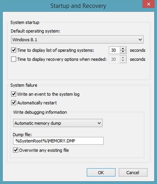
Figure 1-1. Configure system startup options.
Managing system boot configuration
The System Configuration utility (Msconfig.exe) enables you to fine-tune the way a computer starts. Typically, you use this utility during troubleshooting and diagnostics. For example, as part of troubleshooting, you can configure the computer to use a diagnostic startup in which only basic devices and services are loaded.
In Control Panel, the System Configuration utility is available under System And Security/Administrative Tools. You can also start the System Configuration utility by pressing the Windows key, typing msconfig.exe (which typically is entered automatically into the Apps Search box), and then pressing Enter. As shown in Figure 1-2, this utility has a series of tabs with options.
The General tab options enable you to configure the way startup works and are the starting point for troubleshooting and diagnostics. By using these options, you can choose to perform a normal startup, diagnostic startup, or selective startup. After you restart the computer and resolve any problems, open the System Configuration utility again, select Normal Startup on the General tab, and then tap or click OK.
The Boot tab options enable you to control the way that individual startup-related processes work. You can configure the computer to start in one of various Safe Boot modes and set additional options, such as No GUI Boot. If, after troubleshooting, you find that you want to keep these settings, select the Make All Boot Settings Permanent check box to save the settings to the boot configuration startup entry.
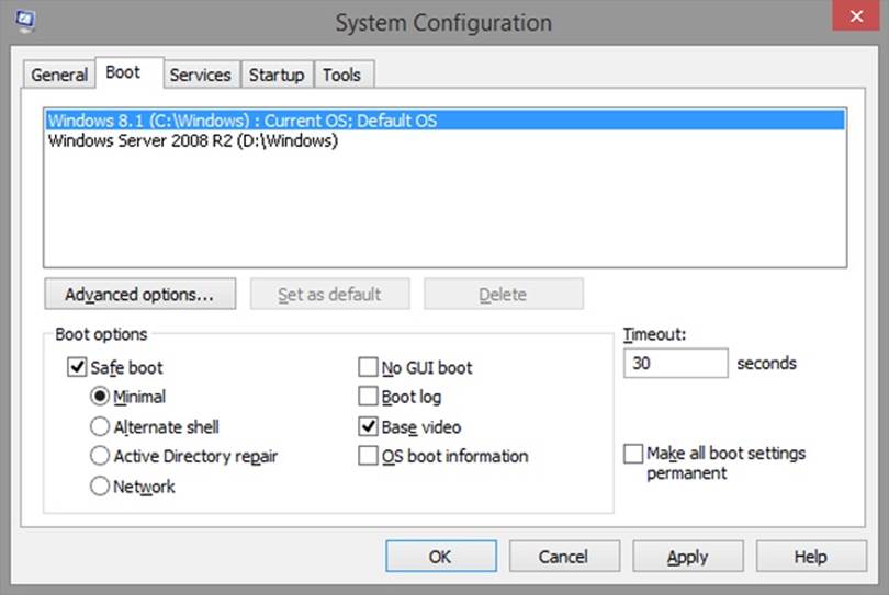
Figure 1-2. Use the System Configuration utility for troubleshooting.
Tapping or clicking the Advanced Options button on the Boot tab displays the BOOT Advanced Options dialog box, shown in Figure 1-3. In addition to locking PCI and enabling debugging, you can use the advanced options to do the following:
§ Specify the number of processors the operating system should use, regardless of whether the processors are discrete socketed CPUs or cores on a single CPU. You should use this option when you suspect a problem with additional processors that are available and you want to identify the problem as being related to multiprocessor configurations or parallelism. Consider the following scenario: A computer is shipped with a single CPU that has four processor cores. A custom application used in-house for inventory management performs very poorly while running on this computer, but very well on computers with single processors. You configure the computer to boot with only one processor and find that the application’s performance actually improves. You re-enable all the processors and let the software development team know that the application behaves as if it has not been properly optimized for parallelism.
§ Specify the maximum amount of memory the operating system should use. Use this option when you suspect a problem with additional memory you’ve installed in a computer. Consider the following scenario: A computer is shipped with 8 gigabytes (GB) of RAM, and you installed another 8 GB of RAM. Later, you find that you cannot start Windows 8.1. You could eliminate the new RAM as the potential cause by limiting the computer to 8,192 megabytes (MB) of memory.
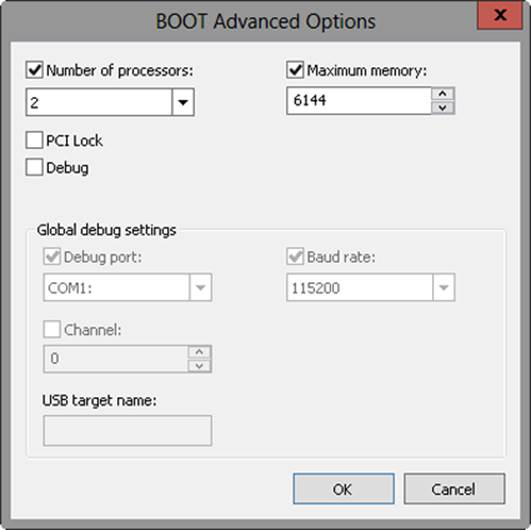
Figure 1-3. Use advanced boot options to help troubleshoot specific types of problems.
If you suspect that services installed on a computer are causing startup problems, you can quickly determine this by choosing a diagnostic or selective startup on the General tab. After you’ve identified that services are indeed causing startup problems, you can temporarily disable services by using the Services tab options and then rebooting to determine if the problem goes away. If the problem no longer appears, you might have pinpointed it. You can then permanently disable the service or check with the service vendor to find out if an updated executable file is available. You disable a service by clearing the related check box on the Services tab.
Similarly, if you suspect applications that run at startup are causing problems, you can quickly determine this by tapping or clicking Open Task Manager on the Startup tab. You disable a startup application by selecting it on the Startup tab and then tapping or clicking Disable. If the problem no longer appears, you might have pinpointed the cause of it. You can then permanently disable the startup application or check with the software vendor to find out if an updated version is available.
Keep in mind that if you use the System Configuration utility for troubleshooting and diagnostics, you should later remove your selective startup options. After you restart the computer and resolve any problems, open the System Configuration utility again, restore the original settings, and then tap or click OK.
Using the BCD Editor
The BCD store contains multiple entries. On a BIOS-based computer, you’ll find the following entries:
§ One Windows Boot Manager entry. There is only one boot manager, so only one boot manager entry is visible.
§ One or more Windows Boot Loader application entries, with one for each instance of Windows Vista or later installed on the computer. If you’ve installed Windows Server 2008 or later, you’ll also find entries for each installation.
Windows Boot Manager is a boot loader application. There are also other boot loader applications, including:
§ Operating system loader, identified as Osloader
§ Windows Boot Sector Application, identified as Bootsector
§ Firmware Boot Manager, identified as Fwbootmgr
§ Windows Resume Loader, identified as Resume
You can view and manage the BCD store by using the BCD Editor (Bcdedit.exe). The BCD Editor is a command-line utility. You can use the BCD Editor to view the entries in the BCD store by following these steps:
1. Enter cmd.exe in the Apps Search box. One way to do this is to press the Windows key, and then enter cmd.exe.
2. Press and hold or right-click the command prompt, and then tap or click Run As Administrator.
3. Enter bcdedit at the command prompt.
Table 1-3 summarizes commands you can use when you are working with the BCD store. These commands make it possible for you to do the following:
§ Create, import, export, and identify the entire BCD store
§ Create, delete, and copy individual entries in the BCD store
§ Set or delete entry option values in the BCD store
§ Control the boot sequence and the boot manager
§ Configure and control Emergency Management Services (EMS)
§ Configure and control boot debugging, in addition to hypervisor debugging
Table 1-3. Commands for the BCD Editor
|
COMMAND |
DESCRIPTION |
|
/bootdebug |
Enables or disables boot debugging for a boot application. |
|
/bootems |
Enables or disables EMS for a boot application. |
|
/bootsequence |
Sets the one-time boot sequence for the boot manager. |
|
/copy |
Makes copies of entries in the store. |
|
/create |
Creates new entries in the store. |
|
/createstore |
Creates a new (empty) boot configuration data store. |
|
/dbgsettings |
Sets the global debugger parameters. |
|
/debug |
Enables or disables kernel debugging for an operating system entry. |
|
/default |
Sets the default entry that the boot manager will use. |
|
/delete |
Deletes entries from the store. |
|
/deletevalue |
Deletes entry options from the store. |
|
/displayorder |
Sets the order in which the boot manager displays the multiboot menu. |
|
/ems |
Enables or disables EMS for an operating system entry. |
|
/emssettings |
Sets the global EMS parameters. |
|
/enum |
Lists entries in the store. |
|
/export |
Exports the contents of the system store to a file. This file can be used later to restore the state of the system store. |
|
/hypervisorsettings |
Sets the hypervisor parameters. |
|
/import |
Restores the state of the system store by using a backup file created with the /export command. |
|
/mirror |
Creates a mirror of entries in the store. |
|
/set |
Sets entry option values in the store. |
|
/store |
Sets the BCD store to use. If not specified, the system store is used. |
|
/sysstore |
Sets the system store device. This only affects EFI systems. |
|
/timeout |
Sets the boot manager timeout value. |
|
/toolsdisplayorder |
Sets the order in which the boot manager displays the tools menu. |
|
/v |
Sets output to verbose mode. |
Managing the BCD store
The BCD Editor is an advanced command-line tool for viewing and manipulating the configuration of the pre–operating system boot environment. Although I discuss tasks related to modifying the BCD data store in the sections that follow, you should attempt to modify the BCD store only if you are an experienced IT pro. As a safeguard, you should make a full backup of the computer prior to making any changes to the BCD store. Why? If you make a mistake, your computer might end up in a nonbootable state, and you would then need to initiate recovery.
Viewing BCD entries
Computers can have system and nonsystem BCD stores. The system BCD store contains the operating system boot entries and related boot settings. Whenever you work with the BCD Editor, you work with the system BCD store.
On a computer with only one operating system, the BCD entries for your computer will look similar to those in Example 1-1. As the listing shows, the BCD store for this computer has two entries: one for the Windows Boot Manager, and one for the Windows Boot Loader. Here, the Windows Boot Manager calls the boot loader, and the boot loader uses Winload.exe to boot Windows 8.1.
Example 1-1. Entries in the BCD Store on a single-boot computer
Windows Boot Manager
--------------------
identifier {bootmgr}
device partition=\Device\HarddiskVolume1
description Windows Boot Manager
locale en-US
inherit {globalsettings}
integrityservices Enable
default {current}
resumeobject {16b857b4-9e02-11e0-9c17-b7d085eb0682}
displayorder {current}
{16b857ad-9e02-11e0-9c17-b7d085eb0682}
toolsdisplayorder {memdiag}
timeout 30
custom:26000025 Yes
Windows Boot Loader
-------------------
identifier {current}
device partition=C:
path \Windows\system32\winload.exe
description Windows 8.1
locale en-US
inherit {bootloadersettings}
recoverysequence {16b857b6-9e02-11e0-9c17-b7d085eb0682}
integrityservices Enable
recoveryenabled Yes
allowedinmemorysettings 0x15000075
osdevice partition=C:
systemroot \Windows
resumeobject {16b857b4-9e02-11e0-9c17-b7d085eb0682}
nx OptIn
bootmenupolicy Standard
BCD entries for Windows Boot Manager and Windows Boot Loader have similar properties. These properties include those summarized in Table 1-4.
Table 1-4. BCD entry properties
|
PROPERTY |
DESCRIPTION |
|
Description |
Shows descriptive information to help identify the type of entry. |
|
Device |
Shows the physical device path. For a partition on a physical disk, you’ll find an entry such as partition=C:. |
|
FileDevice |
Shows the path to a file device, such as partition=C:. |
|
FilePath |
Shows the file path to a necessary file, such as \Hiberfil.sys. |
|
Identifier |
Shows a descriptor for the entry. This can be a boot loader application type, such as Bootmgr or Ntldr, a reference to the current operating system entry, or the globally unique identifier (GUID) of a specific object. Well-known identifiers are listed in Table 1-5, later in this chapter. |
|
Inherit |
Shows the list of entries to be inherited. |
|
Locale |
Shows the computer’s locale setting, such as en-US. The locale setting determines the language shown in the user interface (UI). The \Boot folder contains locale subfolders for each locale supported, and each of these subfolders has language-specific UI details for the Windows Boot Manager and the Windows Memory Diagnostic utility (Memdiag.exe). |
|
Osdevice |
Shows the path to the operating system device, such as partition=C:. |
|
Path |
Shows the actual file path to the boot loader application, such as \Windows\System32\Winload.exe. |
When you are working with the BCD store and the BCD Editor, you’ll find references to well-known identifiers, summarized in Table 1-5, in addition to GUIDs. When a GUID is used, it has the following format, where each N represents a hexadecimal value:
{NNNNNNNN-NNNN-NNNN-NNNN-NNNNNNNNNNNN}
such as:
{16b857ad-9e02-11e0-9c17-b7d085eb0682}
The dashes that separate the parts of the GUID must be entered in the positions shown. Both well-known identifiers and GUIDs are enclosed in braces.
Table 1-5. Well-known identifiers
|
IDENTIFIER |
DESCRIPTION |
|
{badmemory} |
Contains the global RAM defect list that can be inherited by any boot application entry. |
|
{bootloadersettings} |
Contains the collection of global settings that should be inherited by all Windows Boot Loader application entries. |
|
{bootmgr} |
Indicates the Windows Boot Manager entry. |
|
{current} |
Represents a virtual identifier that corresponds to the operating system boot entry for the operating system that is currently running. |
|
{dbgsettings} |
Contains the global debugger settings that can be inherited by any boot application entry. |
|
{default} |
Represents a virtual identifier that corresponds to the boot manager default application entry. |
|
{emssettings} |
Contains the global EMS settings that can be inherited by any boot application entry. |
|
{fwbootmgr} |
Indicates the firmware boot manager entry. This entry is used on EFI systems. |
|
{globalsettings} |
Contains the collection of global settings that should be inherited by all boot application entries. |
|
{hypervisorsettings} |
Contains the hypervisor settings that can be inherited by any operating system loader entry. |
|
{memdiag} |
Indicates the memory diagnostic application entry. |
|
{ntldr} |
Indicates the Windows Legacy OS Loader (Ntldr) that can be used to start Windows operating systems earlier than Windows Vista. Used when you’ve installed a legacy operating system. |
|
{ramdiskoptions} |
Contains the additional options required by the boot manager for RAM disk devices. |
|
{resumeloadersettings} |
Contains the collection of global settings that should be inherited by all Windows resume-from-hibernation application entries. |
When a computer has additional instances of Windows installed, the BCD store has additional entries for each additional operating system. For example, the BCD store might have one entry for the Windows Boot Manager and one Windows Boot Loader entry for each operating system.
Although the Windows Boot Manager and Windows Boot Loader are the primary types of entries that control startup, the BCD store also includes information about boot settings and boot utilities. The Windows Boot Loader entry can have parameters that track the status of boot settings, such as whether No Execute (NX) policy is set to Opt In or Opt Out. The Windows Boot Loader entry also can provide information about available boot utilities, such as the Windows Memory Diagnostic utility.
To view the actual value of the GUIDs needed to manipulate entries in the BCD store, enter bcdedit /v at an elevated command prompt.
Creating and identifying the BCD store
By using the BCD Editor, you can create a nonsystem BCD store by using the following command:
bcdedit /createstore StorePath
StorePath is the folder path to the location where you want to create the nonsystem store, such as:
bcdedit /createstore c:\non-sys\bcd
On an EFI system, you can temporarily set the system store device by using the /sysstore command. Use the following syntax:
bcdedit /sysstore StoreDevice
StoreDevice is the actual system store device identifier, such as:
bcdedit /sysstore c:
The device must be a system partition. Note that this setting does not persist across reboots and is used only in cases in which it is not clear which system store device should be used.
Importing and exporting the BCD store
The BCD Editor provides separate commands for importing and exporting the BCD store. You can use the /export command to export a copy of the system BCD store’s contents to a specified folder. Use the following command syntax:
bcdedit /export StorePath
StorePath is the actual folder path to which you want to export a copy of the system store, such as:
bcdedit /export c:\backup\bcd
To restore an exported copy of the system store, you can use the /import command. Use the following command syntax:
bcdedit /import ImportPath
ImportPath is the actual folder path from which you want to import a copy of the system store, such as:
bcdedit /import c:\backup\bcd
On an EFI system, you can add /clean to the /import command to specify that all existing firmware boot entries should be deleted. Here is an example:
bcdedit /import c:\backup\bcd /clean
Creating and deleting BCD entries
The BCD Editor provides separate commands for creating, copying, and deleting entries in the BCD store. You can use the /create command to create identifier, application, and inherit entries in the BCD store.
As shown previously in Table 1-5, the BCD Editor recognizes many well-known identifiers, including {dbgsettings}, which is used to create a debugger settings entry; {ntldr}, used to create a Windows Legacy OS entry; and {ramdiskoptions}, used to create a RAM disk additional options entry. To create identifier entries, you use the following syntax:
bcdedit /create Identifier /d "Description"
Identifier is a well-known identifier for the entry you want to create, such as:
bcdedit /create {ntldr} /d "Legacy Windows OS Loader"
You can also create entries for specific boot loader applications, including:
§ Bootsector Identifies a real-mode boot sector application; used to set the boot sector for a real-mode application
§ Osloader Identifies an operating system loader application; used to load Windows Vista or later
§ Resume Identifies a Windows Resume Loader application; used to resume the operating system from hibernation
§ Startup Identifies a real-mode application
Use the following command syntax:
bcdedit /create /application AppType /d "
Description"
AppType is one of the previously listed application types, such as:
bcdedit /create /application osloader /d "Windows 8.1"
You can delete entries in the system store by using the /delete command and the following syntax:
bcdedit /delete Identifier
If you are trying to delete a well-known identifier, you must use the /f command to force deletion, such as:
bcdedit /delete {ntldr} /f
By default, when the /delete command is used, the /cleanup option is implied, which means that the BCD Editor cleans up any other references to the entry being deleted. This ensures that the data store doesn’t have invalid references to the identifier you removed. Because entries are also removed from the display order, this could result in a different default operating system being set. If you want to delete the entry and clean up all other references except the display order entry, you can use the /nocleanup command.
Setting BCD entry values
After you create an entry, you need to set additional entry option values as necessary. The basic syntax for setting values is:
bcdedit /set Identifier Option Value
Identifier is the identifier of the entry to be modified, Option is the option you want to set, and Value is the option value, such as:
bcdedit /set {current} device partition=d:
To delete options and their values, use the /deletevalue command with the following syntax:
bcdedit /deletevalue Identifier Option
Identifier is the identifier of the entry to be modified, and Option is the option you want to delete, such as:
bcdedit /deletevalue {current} badmemorylist
When you are working with options, Boolean values can be entered in several different ways. For True, you can use 1, On, Yes, or True. For False, you can use 0, Off, No, or False.
To view the BCD entries for all boot utilities and the values for settings, enter bcdedit /enum all /v at an elevated command prompt. This command enumerates all BCD entries regardless of their current state and lists them in verbose mode. Each additional entry has a specific purpose and lists values that you can set, including the following:
§ Resume From Hibernate The Resume From Hibernate entry shows the current configuration for the resume feature. The pre–operating system boot utility that controls resume is Winresume.exe, which in this example is stored in the C:\Windows\System32 folder. The hibernation data, as specified in the FilePath parameter, is stored in the Hiberfil.sys file in the root folder on the OSDevice (C: in this example). Because the resume feature works differently if the computer has Physical Address Extension (PAE) and debugging enabled, these options are tracked by the PAE and DebugOptionEnabled parameters.
§ Windows Memory Tester The Windows Memory Tester entry shows the current configuration for the Windows Memory Diagnostic utility. Memtest is the pre–operating system boot utility that controls memory diagnostics. Because the Windows Memory Diagnostic utility is designed to detect bad memory by default, the BadMemoryAccess parameter is set to Yes by default. You can turn this feature off by entering bcdedit /set {memdiag} badmemoryaccess NO. With memory diagnostics, you can configure the number of passes by using Passcount and the test mix as Basic or Extended by using Testmix. Here is an example: bcdedit /set {memdiag} passcount 2 textmix basic.
§ Windows Legacy OS Loader The Windows Legacy OS Loader entry shows the current configuration for the loading of earlier versions of Windows. The Device parameter sets the default partition to use, such as C:, and the Path parameter sets the default path to the loader utility, such as Ntldr.
§ EMS Settings The EMS Settings entry shows the configuration used when booting with EMS. Individual Windows Boot Loader entries control whether EMS is enabled. If EMS is provided by the BIOS and you want to use the BIOS settings, you can enter bcdedit /emssettings bios. With EMS, you can set an EMS port and an EMS baud rate. Here is an example: bcdedit /emssettings EMSPORT:2 EMSBAUDRATE:115200. You can enable or disable EMS for a boot application by using /bootems, following the identity of the boot application with the state you want, such as On or Off.
§ Debugger Settings The Debugger Settings entry shows the configuration used when booting with the debugger turned on. Individual Windows Boot Loader entries control whether the debugger is enabled. You can view the hypervisor debugging settings by entering bcdedit /dbgsettings. When debug booting is turned on, DebugType sets the type of debugger as SERIAL, 1394, or USB. With SERIAL debugging, DebugPort specifies the serial port being used as the debugger port, and BaudRate specifies the baud rate to be used for debugging. With 1394 debugging, you can use Channel to set the debugging channel. With USB debugging, you can use TargetName to set the USB target name to be used for debugging. With any debug type, you can use the /Noumex flag to specify that user-mode exceptions should be ignored. Here are examples of setting the debugging mode: bcdedit /dbgsettings SERIAL DEBUGPORT:1 BAUDRATE:115200, bcdedit /dbgsettings 1394 CHANNEL:23, bcdedit /dbgsettings USB TARGETNAME:DEBUGGING.
§ Hypervisor Settings The Hypervisor Settings entry shows the configuration used when working with the hypervisor with the debugger turned on. Individual Windows Boot Loader entries control whether the debugger is enabled. You can view the hypervisor debugging settings by entering bcdedit /hypervisorsettings. When hypervisor debug booting is turned on, HypervisorDebugType sets the type of debugger, HypervisorDebugPort specifies the serial port being used as the debugger port, and Hypervisor-BaudRate specifies the baud rate to be used for debugging. These parameters work the same as with Debugger Settings. Here is an example: bcdedit /hypervisorsettings SERIAL DEBUGPORT:1 BAUDRATE:115200. You can also use FireWire for hypervisor debugging. When you do, you must separate the word channel from the value with a colon, as shown in this example: bcdedit /hypervisorsettings 1394 CHANNEL:23.
Table 1-6 summarizes key options that apply to entries for boot applications (Bootapp). Because Windows Boot Manager, Windows Memory Diagnostic, Windows OS Loader, and Windows Resume Loader are boot applications, these options also apply to them.
Table 1-6. Key options for boot application entries
|
OPTION |
VALUE DESCRIPTION |
|
BadMemoryAccess |
When true, enables an application to use the memory on the bad memory list. When false, applications are prevented from using memory on the bad memory list. |
|
BadMemoryList |
An integer list that defines the list of Page Frame Numbers of faulty memory in the system. |
|
BaudRate |
Sets an integer value that defines the baud rate for the serial debugger. |
|
BootDebug |
Sets a Boolean value that enables or disables the boot debugger. |
|
BootEMS |
Sets a Boolean value that enables or disables EMS. |
|
Channel |
Sets an integer value that defines the channel for the 1394 debugger. |
|
ConfigAccessPolicy |
Sets the access policy as either DEFAULT or DISALLOWMMCONFIG. |
|
DebugAddress |
Sets an integer value that defines the address of a serial port for the debugger. |
|
DebugPort |
Sets an integer value that defines the serial port number for the serial debugger. |
|
DebugStart |
Can be set to ACTIVE, AUTOENABLE, or DISABLE. |
|
DebugType |
Can be set to SERIAL, 1394, or USB. |
|
EMSBaudRate |
Defines the baud rate for EMS. |
|
EMSPort |
Defines the serial port number for EMS. |
|
FirstMegaBytePolicy |
Sets the first megabyte policy as USENONE, USEALL, or USEPRIVATE. |
|
GraphicsModeDisabled |
Sets a Boolean value that enables or disables graphics mode. |
|
GraphicsResolution |
Defines the graphics resolution, such as 1024 x 768 or 800 x 600. |
|
Locale |
Sets the locale of the boot application. |
|
Noumex |
When Noumex is set to TRUE, user-mode exceptions are ignored. When Noumex is set to FALSE, user-mode exceptions are not ignored. |
|
NoVESA |
Sets a Boolean value that enables or disables the use of Video Electronics Standards Association (VESA) display modes. |
|
RecoveryEnabled |
Sets a Boolean value that enables or disables the use of a recovery sequence. |
|
RecoverySequence |
Defines the recovery sequence to use. |
|
TargetName |
Defines the target name for the USB debugger as a string. |
|
TestSigning |
Sets a Boolean value that enables or disables use of prerelease test-code signing certificates. |
|
TruncateMemory |
Sets a physical memory address at or above which all memory is disregarded. |
Table 1-7 summarizes key options that apply to entries for Windows OS Loader (Osloader) applications.
Table 1-7. Key options for Windows OS Loader applications
|
OPTION |
VALUE DESCRIPTION |
|
AdvancedOptions |
Sets a Boolean value that enables or disables advanced options. |
|
BootLog |
Sets a Boolean value that enables or disables the boot initialization log. |
|
BootStatusPolicy |
Sets the boot status policy. Can be DisplayAllFailures, IgnoreAllFailures, IgnoreShutdownFailures, or IgnoreBootFailures. |
|
ClusterMode Addressing |
Sets the maximum number of processors to include in a single Advanced Programmable Interrupt Controller (APIC) cluster. |
|
ConfigFlags |
Sets processor-specific configuration flags. |
|
DbgTransport |
Sets the file name for a private debugger transport. |
|
Debug |
Sets a Boolean value that enables or disables kernel debugging. |
|
DriverLoad FailurePolicy |
Sets the driver load failure policy. Can be Fatal or UseErrorControl. |
|
Ems |
Sets a Boolean value that enables or disables kernel EMS. |
|
Hal |
Sets the file name for a private HAL. |
|
HalBreakPoint |
Sets a Boolean value that enables or disables the special HAL breakpoint. |
|
HypervisorLaunchType |
Configures the hypervisor launch type. Can be Off or Auto. |
|
IncreaseUserVA |
Sets an integer value (in megabytes) that increases the amount of virtual address space that the user-mode processes can use. |
|
Kernel |
Sets the file name for a private kernel. |
|
LastKnownGood |
Sets a Boolean value that enables or disables booting to the last known good configuration. |
|
MaxProc |
Sets a Boolean value that enables or disables the display of the maximum number of processors in the system. |
|
Msi |
Sets the message signaled interrupt (MSI). Can be Default or ForceDisable. |
|
NoCrashAutoReboot |
Sets a Boolean value that enables or disables automatic restart on crash. |
|
NoLowMem |
Sets a Boolean value that enables or disables the use of low memory. |
|
NumProc |
Sets the number of processors to use on startup. |
|
Nx |
Controls no-execute protection. Can be OptIn, OptOut, AlwaysOn, or AlwaysOff. |
|
OneCPU |
Sets a Boolean value that forces or does not force only the boot CPU to be used. |
|
OptionsEdit |
Sets a Boolean value that enables or disables the options editor. |
|
OSDevice |
Defines the device that contains the system root. |
|
Pae |
Controls PAE. Can be Default, ForceEnable, or ForceDisable. |
|
PerfMem |
Sets the size (in megabytes) of the buffer to allocate for performance data logging. |
|
RemoveMemory |
Sets an integer value (in megabytes) that removes memory from the total available memory that the operating system can use. |
|
RestrictAPICCluster |
Sets the largest APIC cluster number to be used by the system. |
|
ResumeObject |
Sets the identifier for the resume object that is associated with this operating system object. |
|
SafeBoot |
Sets the computer to use a Safe Boot mode. Can be Minimal, Network, or DsRepair. |
|
SafeBoot AlternateShell |
Sets a Boolean value that enables or disables the use of the alternate shell when booted into safe mode. |
|
Sos |
Sets a Boolean value that enables or disables the display of additional boot information. |
|
SystemRoot |
Defines the path to the system root. |
|
UseFirmwarePCISettings |
Sets a Boolean value that enables or disables use of BIOS-configured PCI resources. |
|
UsePhysical Destination |
Sets a Boolean value that forces or does not force the use of the physical APIC. |
|
Vga |
Sets a Boolean value that forces or does not force the use of the VGA display driver. |
|
WinPE |
Sets a Boolean value that enables or disables booting to Windows Preinstallation Environment (Windows PE). |
Changing Data Execution Prevention and Physical Address Extension options
Data Execution Prevention (DEP) is a memory-protection technology. Windows 8 and Windows 8.1 are the first versions of Windows that require a processor that supports DEP. Windows 8 and Windows 8.1 will not install on computers that aren’t DEP-enabled.
When DEP is enabled, the computer’s processor marks all memory locations in an application as nonexecutable unless the location explicitly contains executable code. If code is executed from a memory page marked as nonexecutable, the processor can raise an exception and prevent the code from executing. This behavior prevents malicious application code, such as virus code, from inserting itself into most areas of memory.
For computers with processors that support the non-execute (NX) page-protection feature, you can configure the operating system to opt in to NX protection by setting the nx parameter to OptIn, or opt out of NX protection by setting the nx parameter to OptOut. Here is an example:
bcdedit /set {current} nx optout
When you configure NX protection to OptIn, DEP is turned on only for essential Windows programs and services. This is the default. When you configure NX protection to OptOut, all programs and services—not just standard Windows programs and services—use DEP. Programs that shouldn’t use DEP must be specifically opted out. You can also configure NX protection to be always on or always off by using AlwaysOn or AlwaysOff, such as:
bcdedit /set {current} nx alwayson
NOTE
You opt out of programs by using advanced system settings. In Control Panel, select System And Security, select System, and then select Advanced System Settings. This opens the System Properties dialog box to the Advanced tab. Select Settings on the Performance panel of the Advanced tab. On the Data Execution Prevention tab in the Performance Options dialog box, select Turn On DEP For All Programs Except Those I Select. Finally, click Add to specify a program that shouldn’t use DEP.
Processors that support and opt in to NX protection must be running in PAE mode. You can configure PAE by setting the PAE parameter to Default, ForceEnable, or ForceDisable. When you set the PAE state to Default, the operating system uses its default configuration for PAE. When you set the PAE state to ForceEnable, the operating system uses PAE. When you set the PAE state to ForceDisable, the operating system will not use PAE. Here is an example:
bcdedit /set {current} pae default
Changing the operating system display order
You can change the display order of boot managers associated with a particular installation of Windows by using the /displayorder command. The syntax is:
bcdedit /displayorder id1 id2 ... idn
id1 is the operating system identifier of the first operating system in the display order, id2 is the identifier of the second, and so on. You could change the display order of the operating systems identified in these BCD entries:
Windows Boot Loader
-------------------
identifier {16b857b4-9e02-11e0-9c17-b7d085eb0682}
Windows Boot Loader
-------------------
identifier {14504de-e96b-11cd-a51b-89ace9305d5e}
Windows Boot Loader
-------------------
identifier {8b78e48f-02d0-11dd-af92-a72494804a8a}
by using the following command:
bcdedit /displayorder {8b78e48f-02d0-11dd-af92-a72494804a8a}
{16b857b4-9e02-11e0-9c17-b7d085eb0682}
{14504de-e96b-11cd-a51b-89ace9305d5e}
You can set a particular operating system as the first entry by using /addfirst with /displayorder, as in:
bcdedit /displayorder {16b857b4-9e02-11e0-9c17-b7d085eb0682} /addfirst
You can set a particular operating system as the last entry by using /addlast with /displayorder, as in:
bcdedit /displayorder {8b78e48f-02d0-11dd-af92-a72494804a8a} /addlast
Changing the default operating system entry
You can change the default operating system entry by using the /default command. The syntax for this command is:
bcdedit /default id
id is the operating system ID in the boot loader entry. You could set the operating system identified in this BCD entry as the default:
Windows Boot Loader
-------------------
identifier {16b857b4-9e02-11e0-9c17-b7d085eb0682}
by using the following command:
bcdedit /default {16b857b4-9e02-11e0-9c17-b7d085eb0682}
If you want to use a legacy operating system, such as Windows XP, as the default, use the identifier for the Windows Legacy OS Loader. The related BCD entry looks like this:
Windows Legacy OS Loader
------------------------
identifier {466f5a88-0af2-4f76-9038-095b170dc21c}
device partition=C:
path \ntldr
description Early Microsoft Windows Operating System
Following this, you could set Ntldr as the default by entering:
bcdedit /default {466f5a88-0af2-4f76-9038-095b170dc21c}
Changing the default timeout
You can change the timeout value associated with the default operating system by using the /timeout command. Set the /timeout command to the wait time you want to use (in seconds) as follows:
bcdedit /timeout 30
To boot automatically to the default operating system, set the timeout to 0 seconds.
Changing the boot sequence temporarily
Occasionally, you might want to boot to a particular operating system one time and then revert to the default boot order. To do this, you can use the /bootsequence command. Follow the command with the identifier of the operating system to which you want to boot after restarting the computer, such as:
bcdedit /bootsequence {16b857b4-9e02-11e0-9c17-b7d085eb0682}
When you restart the computer, the computer will set the specified operating system as the default for that restart only. Then, when you restart the computer again, the computer will use the original default boot order.
All materials on the site are licensed Creative Commons Attribution-Sharealike 3.0 Unported CC BY-SA 3.0 & GNU Free Documentation License (GFDL)
If you are the copyright holder of any material contained on our site and intend to remove it, please contact our site administrator for approval.
© 2016-2026 All site design rights belong to S.Y.A.