CCNA Wireless 200-355 Official Cert Guide (2016)
Chapter 20. Troubleshooting WLAN Connectivity
This chapter covers the following topics:
![]() Troubleshooting Client Connectivity—This section covers some strategies and methods you can use when faced with wireless clients that report problems connecting to the network.
Troubleshooting Client Connectivity—This section covers some strategies and methods you can use when faced with wireless clients that report problems connecting to the network.
![]() Troubleshooting AP Connectivity—This section describes some troubleshooting steps you can use to figure out why an access point is not connecting or operating properly.
Troubleshooting AP Connectivity—This section describes some troubleshooting steps you can use to figure out why an access point is not connecting or operating properly.
![]() Checking the RF Environment—This section provides an overview of third-party tools that you can leverage to detect the presence of APs and SSIDs at a location. It also covers tools that scan channels, map 802.11 activity, analyze wireless traffic, and analyze the RF spectrum.
Checking the RF Environment—This section provides an overview of third-party tools that you can leverage to detect the presence of APs and SSIDs at a location. It also covers tools that scan channels, map 802.11 activity, analyze wireless traffic, and analyze the RF spectrum.
This chapter covers the following exam topics:
![]() 6.0—Performing Client Connectivity Troubleshooting
6.0—Performing Client Connectivity Troubleshooting
![]() 6.1—Validating WLAN configuration settings at the infrastructure side
6.1—Validating WLAN configuration settings at the infrastructure side
![]() 6.1a—Security settings
6.1a—Security settings
![]() 6.1b—SSID settings
6.1b—SSID settings
![]() 6.2—Validating AP infrastructure settings
6.2—Validating AP infrastructure settings
![]() 6.2a—Port level configuration
6.2a—Port level configuration
![]() 6.2b—Power source
6.2b—Power source
![]() 6.2c—AP and antenna orientation and position
6.2c—AP and antenna orientation and position
![]() 6.3—Validate client settings
6.3—Validate client settings
![]() 6.3a—SSID
6.3a—SSID
![]() 6.3b—Security
6.3b—Security
![]() 6.4—Employ appropriate controller tools to assist troubleshooting
6.4—Employ appropriate controller tools to assist troubleshooting
![]() 6.4a—GUI logs
6.4a—GUI logs
![]() 6.4b—CLI show commands
6.4b—CLI show commands
![]() 6.5—Identify appropriate third-party tools to assist troubleshooting
6.5—Identify appropriate third-party tools to assist troubleshooting
![]() 6.5a—OS-based Client utilities
6.5a—OS-based Client utilities
![]() 6.5b—Wi-Fi scanners
6.5b—Wi-Fi scanners
![]() 6.5c—RF mapping tool
6.5c—RF mapping tool
As a CCNA Wireless engineer, you will be expected to perform some basic troubleshooting work when wireless problems arise. The CCNA Wireless exam blueprint focuses on some troubleshooting tools that are available on Cisco Wireless LAN Controllers (WLCs), Wireless Controller Modules (WCMs), and Prime Infrastructure (PI), as well as some third-party tools. This chapter helps you get some perspective on wireless problems, develop a troubleshooting strategy, and become comfortable using the tools at your disposal.
“Do I Know This Already?” Quiz
The “Do I Know This Already?” quiz allows you to assess whether you should read this entire chapter thoroughly or jump to the “Exam Preparation Tasks” section. If you are in doubt about your answers to these questions or your own assessment of your knowledge of the topics, read the entire chapter. Table 20-1 lists the major headings in this chapter and their corresponding “Do I Know This Already?” quiz questions. You can find the answers in Appendix A, “Answers to the ‘Do I Know This Already?’ Quizzes.”
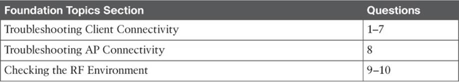
Table 20-1 “Do I Know This Already?” Section-to-Question Mapping
Caution
The goal of self-assessment is to gauge your mastery of the topics in this chapter. If you do not know the answer to a question or are only partially sure of the answer, you should mark that question as wrong for purposes of the self-assessment. Giving yourself credit for an answer you correctly guess skews your self-assessment results and might provide you with a false sense of security.
1. To get PI or a wireless controller to display information about a specific wireless client, you go to the Monitor > Clients page. Which one of the following pieces of information should you input to obtain the best troubleshooting data?
a. WLC IP address
b. SSID
c. Client’s MAC address
d. AP name
2. Which one of the following states indicates that a wireless client has met all of the requirements to begin using a wireless network?
a. 8021X_REQD
b. START
c. RUN
d. L2AUTHCOMPLETE
e. READY
f. COMPLETE
3. Suppose that you search for a wireless client on a controller and notice that it is associated. Which one of the following parameters would confirm that the client has completed the association process with the controller and is ready to pass data?
a. Client’s IP address
b. AP name and IP address
c. Associated AP status
d. RUN policy manager state
4. If a client is shown to be in the 8021X_REQD state, even though the end user tried to join the wireless network several minutes ago, which one of the following best describes the client’s current condition?
a. The client does not support any of the 802.11 amendments.
b. The client failed to authenticate itself properly.
c. Spanning Tree Protocol is blocking the AP’s uplink.
d. The client failed to receive an IP address.
5. To troubleshoot a client’s connection to the wireless network, you decide to use a link test from the controller. The client is a Windows-based machine, uses an adapter that supports 802.11n, is configured to support all possible data rates, and supports CCXv1. Which one of the following link tests will the controller perform with the client?
a. CCXv1 test frames
b. ICMP echo packets
c. Round-trip time (RTT) measurements
d. RSSI measurements at client and AP
6. Which of the following are required on the client’s wireless adapter before a CCX link test can be performed on a controller? (Select all that apply.)
a. CCXv1
b. CCXv2
c. CCXv4
d. CCXv5
e. Support for any CCX version
7. Suppose that you have a large wireless network with several controllers, many APs, a RADIUS server, a syslog server, and Prime Infrastructure. A user has reported connectivity problems in a specific building location, but gave no details about the AP or controller he tried to join. Which one of the following represents the most efficient troubleshooting method you can use to find information about the client?
a. Go to the client’s location and use your own computer to associate with the network, then find out which AP and controller you are using
b. Search for the client’s MAC address on each controller
c. Search for the client’s MAC address on Prime Infrastructure
d. Search for the client’s MAC address on the RADIUS server
8. To find a client from a wireless controller GUI, which one of the following should you select?
a.Find > Clients
b.Monitor > Clients
c.Management > Clients
d.Monitor > Summary
9. Suppose that you have just received news that no users can connect with a newly installed lightweight AP. You decide to examine the switch configuration where the AP is connected, knowing that it needs to be bound to VLAN 11. Which one of the following switch interface configurations is correct?
a.switchport
switchport mode access
no shutdown
b.switchport
switchport trunk allowed vlan 1-11
switchport trunk encapsulation dot1q
switchport mode trunk
c.switchport
switchport access vlan 11
switchport mode access
spanning-tree portfast
shutdown
d.switchport
switchport access vlan 11
switchport mode access
no shutdown
10. Suppose you would like to scan the channels in the 5-GHz band to see which SSIDs are available to clients on which channels in a certain area. Which one of the following tools is a Wi-Fi scanner that is suited for this purpose?
a. Ekahau Site Survey Pro
b. Savvius OmniPeek
c. MetaGeek inSSIDer Office
d. AirMagnet Spectrum XT
11. Ekahau Site Survey Pro is an example of which one of the following third-party wireless tools?
a. Spectrum analyzer
b. Packet analyzer
c. RF mapping tool
d. Wi-Fi scanner
Foundation Topics
Troubleshooting Client Connectivity
When one or more network users report that they are having problems, your first course of action should be to gather more information. Begin with a broad perspective and then try to ask pointed questions that will narrow the scope of possible causes. You do not want to panic or waste time chasing irrelevant things. Instead, ask questions and try to notice patterns or similarities in the answers you receive.
For example, if you get reports from many people in the same area, perhaps an AP is misconfigured or malfunctioning. Reports from many areas or from a single service set identifier (SSID) may indicate problems with a controller configuration. However, if you receive a report of only one wireless user having problems, it might not make sense to spend time troubleshooting a controller, where many users are supported. Instead, you should focus on that one user’s client device and its interaction with an AP.
As you prepare to troubleshoot a single wireless client, think about all of the things a client needs to join and use the network. Figure 20-1 illustrates the following conditions that must be met for a successful association:
![]() Client is within RF range of an AP, asks to associate
Client is within RF range of an AP, asks to associate
![]() Client authenticates
Client authenticates
![]() Client requests and receives an IP address
Client requests and receives an IP address
![]()
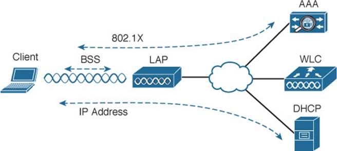
Figure 20-1 Conditions for a Successful Wireless Association
Try to gather information from the end user to see what the client is experiencing. “I cannot connect” or “The Wi-Fi is down” might actually mean that the user’s device cannot associate, cannot get an IP address, or cannot authenticate. A closer inspection of the device might reveal more clues. Therefore, at a minimum, you will need the wireless adapter MAC address from the client device, as well as its physical location. The end user might try to tell you about a specific AP that is in the room or within view. Record that information too, but remember that the client device selects which AP it wants to use—not the human user. The device may well be using a completely different AP.
The sections in this chapter start by focusing on a single client device and then broaden outward, where multiple clients might be affected.
Troubleshooting Clients from PI
Most of your time managing and monitoring a wireless network will be spent in Prime Infrastructure. PI is also a convenient place to begin troubleshooting client connectivity issues. With a little information about the client, PI can display the client’s current state and past history on the wireless network.
You should begin by searching for a client that is having an issue. Enter the client’s wireless MAC address into the search box at the upper-right corner of the PI screen, as shown in Figure 20-2. If PI has been integrated with Cisco Identity Services Engine (ISE) in your environment, you might be able to enter a username into the search field instead.
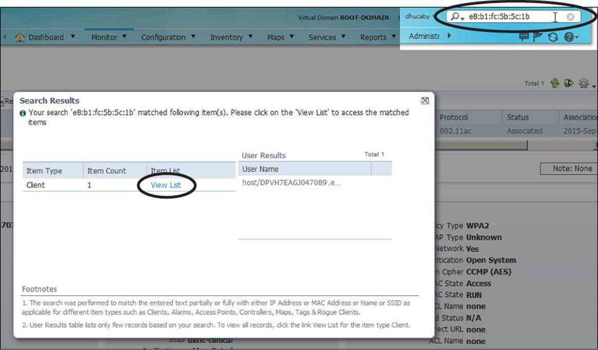
Figure 20-2 Searching for a Client in PI
The Search Results window will list any entries that PI can find about the client. In Figure 20-2, PI has found one instance of client MAC address e8:b1:fc:5b:5c:1b. Click the View List link to display more information about the client. Figure 20-3 shows an example. At a glance, you can see the client’s MAC address, IP address, IP type, username, the wireless network adapter vendor (Intel), location (the name of the PI map, which is obscured in the figure), device name (the WLC or WCM hosting the client), the controller interface (blue), VLAN (36), 802.11 protocol (802.11ac), client status (Associated), and the association time.
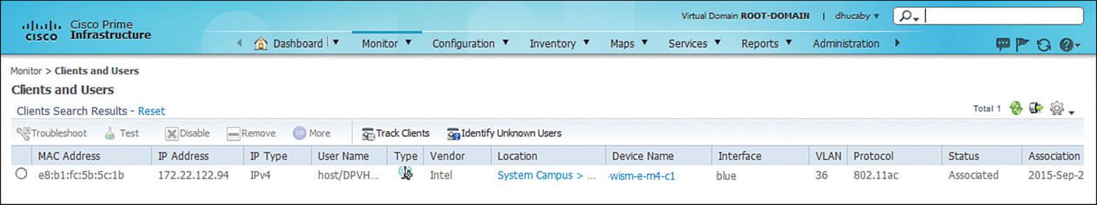
Figure 20-3 Displaying a Client in PI
This is all very helpful information because you may have already learned more about the client. For example, you now know its IP address, a user or host name, which controller it has joined, which controller interface and VLAN it is using, and that it has an active association with an AP.
You can display much more detailed information about the client by clicking the radio button to the left of the client entry. Figure 20-4 continues with the example client, showing details about the client’s general configuration, AP/controller session, and security settings. From this information, you can confirm which 802.11 authentication, wireless security policy, encryption, and Extensible Authentication Protocol (EAP) type the client is using.
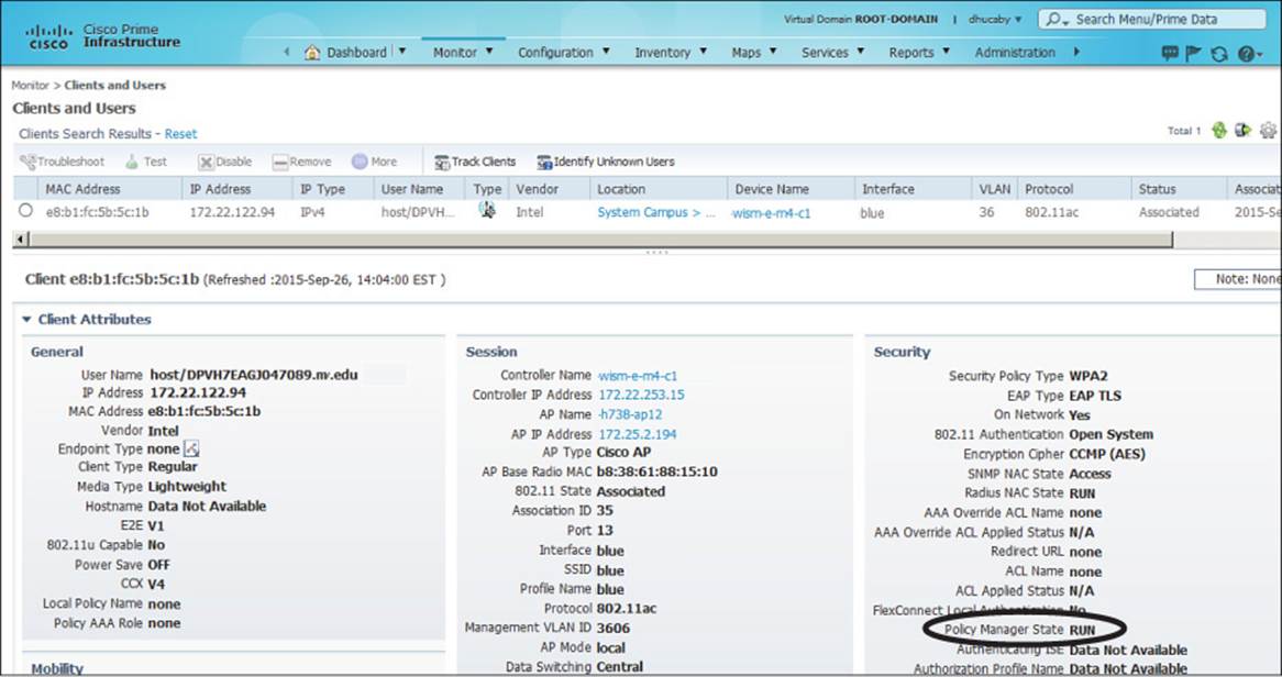
Figure 20-4 Displaying Client Details in PI
Perhaps the most important information about the client is listed as the Policy Manager State, which is circled in Figure 20-4. Before a controller will permit a client to fully associate with a basic service set (BSS), the client must progress through a sequence of states. Each state refers to a policy that the client must meet before moving on to the next state. Table 20-2 lists and describes the client policy states. You should understand the states and what they mean, but you should not spend time memorizing the table.
![]()
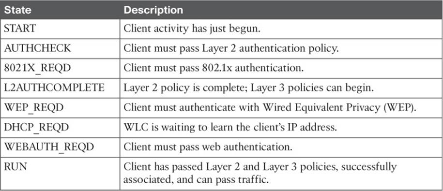
Table 20-2 Possible WLC Client States
A probing client always begins in the START state and then moves into Layer 2 policy states and Layer 3 policy states. For example, if the client is attempting to associate with a WLAN that is configured for some form of 802.1x authentication, the client must pass through the 8021X_REQD state. If it successfully authenticates, it can move further down the list of states.
Ultimately, each client should end up in the RUN state, where it has fully associated with the BSS and is permitted to pass traffic over the WLAN. If you find a client that is consistently shown in a state other than RUN, the client must be having a problem passing the policy of that state.
For example, a client that is stuck in 8021X_REQD is likely having trouble authenticating successfully. That could be because the client is sending an incorrect key or has an invalid certificate, or because the RADIUS server is down.
A client stuck in DHCP_REQD is having trouble obtaining an IP address. The controller monitors the Dynamic Host Configuration Protocol (DHCP) request of each client, as well as the DHCP offer returned to each client. If an offer is not seen, the client is stuck waiting. (One exception is a client that is using a static IP address, without the need for DHCP. So long as the WLAN is configured to not require DHCP, the controller will move the client on through the DHCP_REQD state.)
You can continue to scroll down the Clients and Users screen to see information about the client’s mobility relationship with the wireless network, as shown in Figure 20-5. The client is shown to have mobility status Local, meaning it has not roamed away from the initial controller it joined.
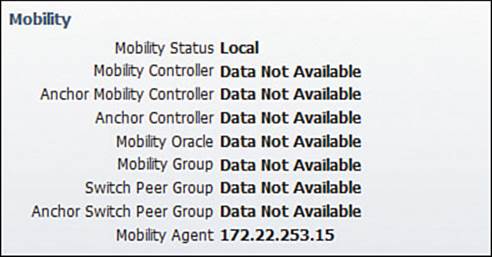
Figure 20-5 Displaying Client Mobility Details
Scroll down further to see detailed information about the client’s 802.11 link with the AP. For example, Figure 20-6 shows receive and transmit counters for the client, as well as its current received signal strength indicator (RSSI), signal-to-noise ratio (SNR), association uptime, current transmit data rate (Modulation Coding Scheme [MCS] value), and supported data rates. From this information, you can verify that the AP is receiving the client with a good, strong signal (–40 dBm) and a good SNR value (57).
![]()
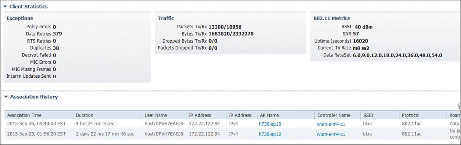
Figure 20-6 Displaying Client RF Statistics
Remember that the SNR measures how many dB the signal is above the noise floor. The SNR can be a low value for the 802.11a/g modulation schemes, higher for 802.11n, and even higher for the greater 802.11ac data rates. With the client’s strong signal and high SNR, you can see that it is able to use MCS 8 and two spatial streams (m8, ss2) with the AP. The client statistics also show some very important counters that relate to the RF conditions. The client has had only 379 data retries or retransmissions out of 13,300 packets transmitted, or a total of 2.8 percent retries. That indicates that the channel is not overutilized and that the client has been very successful at transmitting frames to the AP without contention from other stations on the same channel.
At the bottom of Figure 20-6, notice that PI provides a history of the client’s AP associations over time. Each line represents an association event, with a time stamp and duration, along with the AP and controller names, SSID, 802.11 protocol, and a reason for the event. From the reason listed, you can learn more about why the client changed its association or why the controller updated the entry.
Keep scrolling down to find more useful information about the client’s history on the wireless network. In Figure 20-7, you can see a small map that indicates the current location of the client as a blue square. The map identifies in which campus, building, and floor the client is located, as well as an approximate location within the floor area. This information can be quite useful if you need to physically go and find the client device. After all, the device is probably mobile and may have moved since the time a problem was reported.
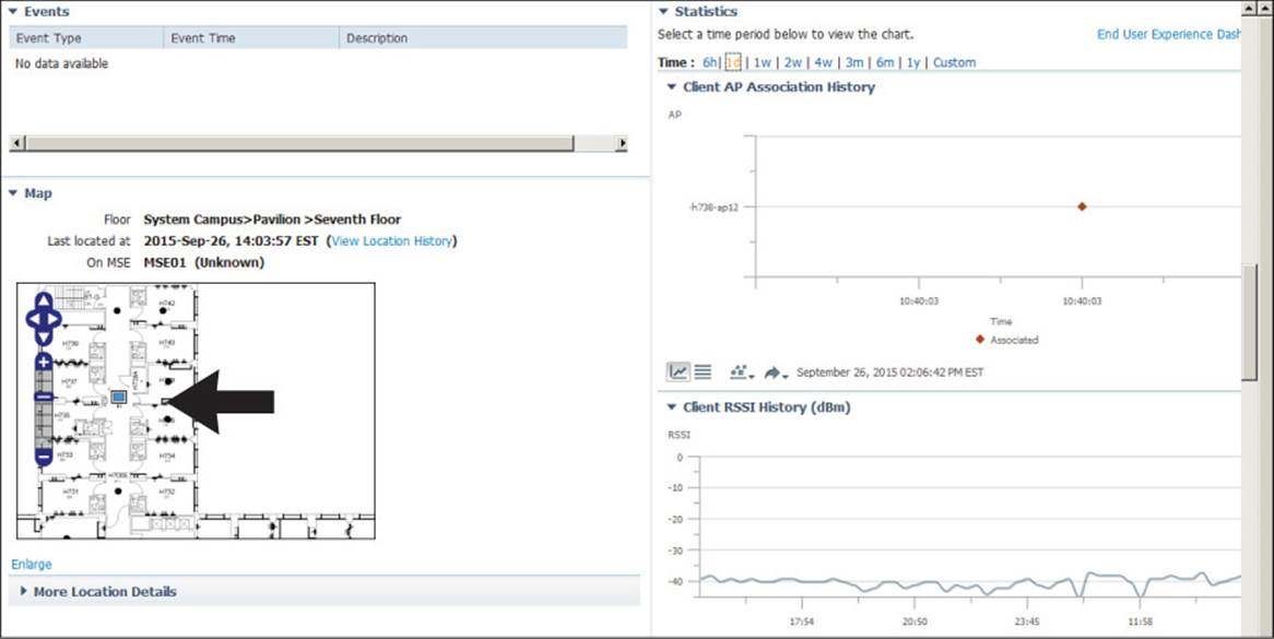
Figure 20-7 Displaying Client Location and RF History
There are also graphs that show when the client changed its associations, along with the client RSSI and SNR, all graphed over time. From Figure 20-7, you can assume that the client has been stationary, because only one AP association is shown on the graph during the past day. You can also see that the RSSI has been steady at around –40 dBm. Although it is not shown in the figure, the SNR has also been steady and strong.
So far, this section has presented results and figures from a client that has a successful association. What should you do with a client that is truly having problems? You should still begin by searching for the client in Prime Infrastructure, then use any detailed information to get more clues about the problem.
For example, suppose you searched for a client that reported connectivity problems and found the information shown in Figure 20-8. Notice that the client has no IP address listed, yet it has an Associated status with the AP. Now look at the Policy Manager State, which is DHCP_REQD instead of RUN. The controller is waiting for the client to successfully obtain an IP address from a DHCP server, but that has not yet completed. Most likely, the DHCP address scope is exhausted or the client is trying to use a static IP address on a WLAN that is configured to require DHCP address assignments.
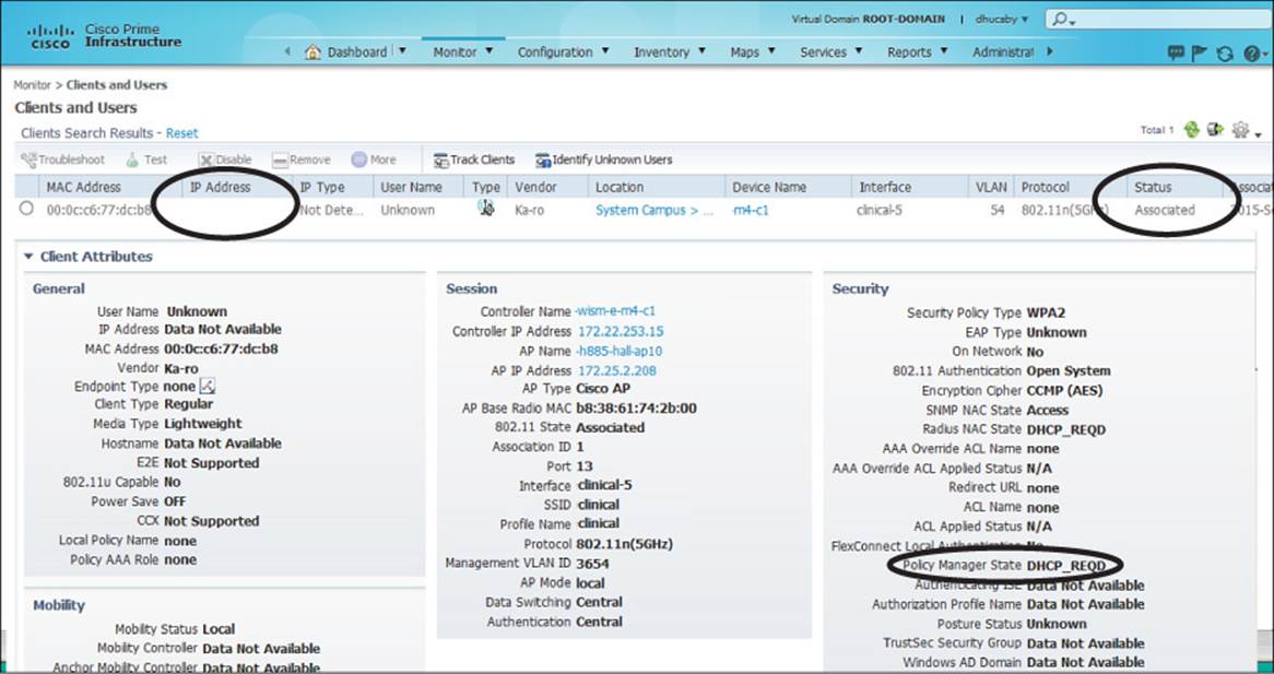
Figure 20-8 Troubleshooting a Client with IP Addressing Problems
Suppose a WLAN is configured to use some form of EAP for client authentication. If a client fails to authenticate correctly, PI will indicate that the controller has kept the client in the DOT1X_REQD state. This can happen if the credentials are entered incorrectly or if a RADIUS server has an expired digital certificate.
PI can also provide some clues about RF problems that a client is experiencing before you have to travel onsite to take further measurements. Figure 20-9 shows an example associated client. The Client Statistics section shows that the client is currently being received at RSSI –71 dBm, with an SNR of 27. Because of the low signal strength and low SNR, the performance must be somewhat low. Out of 586,144 packets transmitted, the client has had 115,091 data retries, or 19.6 percent retransmissions. That might explain why the client has a current Tx rate using the M5 MCS with two spatial streams. Figure 20-10 also shows that the client almost always experiences an RSSI of –70 dBm or less, and an SNR that always hovers between 25 and 30.
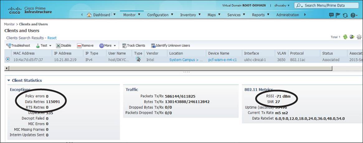
Figure 20-9 Troubleshooting Client RF Problems with PI
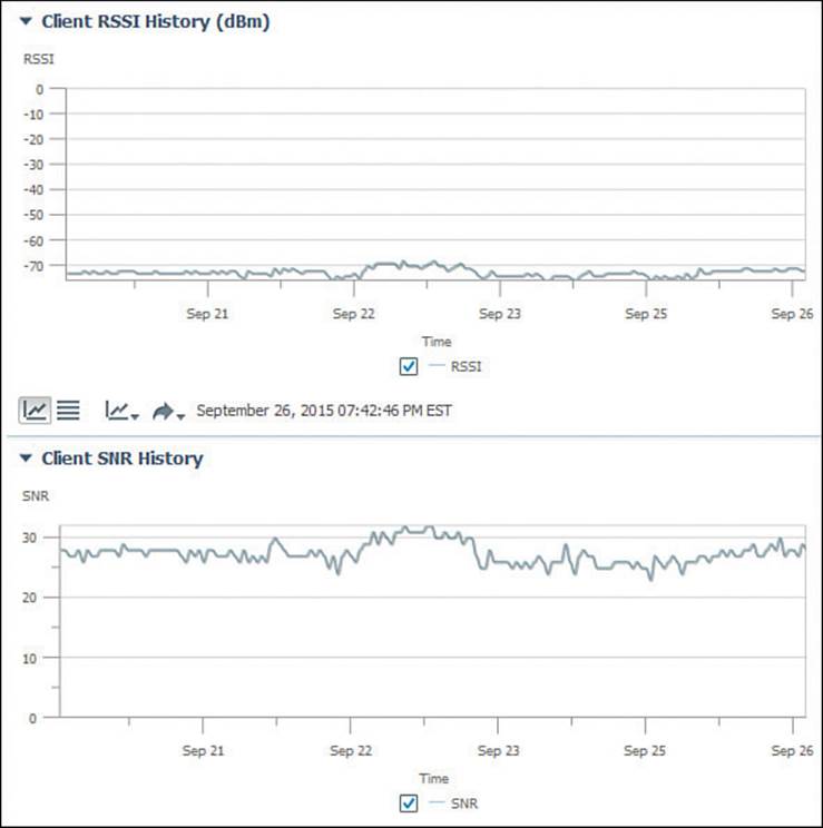
Figure 20-10 Troubleshooting Poor Client RSSI and SNR with PI
Testing a Client from PI
Prime Infrastructure offers a quick way to test the link between the controller and the client device. Once you have searched for a client, select its radio button, then select Test > Link Test above the client list. A short test to gauge the RF conditions between the controller and the client will run and the results will be displayed.
If the client does not support Cisco Compatible Extensions Version 4 (CCXv4) or CCXv5, the controller will run a ping test consisting of 20 500-byte Internet Control Message Protocol (ICMP) echo packets sent to the client’s IP address. The controller should receive replies to each of the ping packets if the wireless link is good and if the client supports ping traffic. The controller also records the RSSI of the client device and the SNR and reports the test results, as shown in Figure 20-11. In this case, the controller sent 20 test packets, but the client echoed only 4 of them back successfully. This could indicate RF problems between the AP and the client.
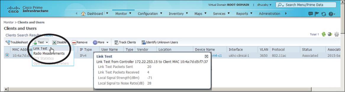
Figure 20-11 Running a Link Test to a Wireless Client
Notice that the ping test reports only a single RSSI value. Even though a wireless link is bidirectional and involves two devices, the AP and the client, the controller can report only on the RSSI of the signal it receives from the client. Naturally, the client can (and probably does) measure the RSSI of the AP’s signal that it receives, but it cannot share that information with the controller using ping packets.
If you perform a link test on a client that does support CCXv4 or CCXv5, the controller can gather much more information about the conditions at both ends of the link. In that case, the link test uses CCX messages rather than pings. The controller can still measure the RSSI of the client’s signal, plus the client can return a message that contains the AP’s RSSI from the client’s perspective. This gives a signal strength reading in both directions.
You can also perform an automatic sequence of troubleshooting steps by selecting a client and then clicking the Troubleshoot button above the client list. PI will check to see if the client has an 802.11 association, if it can pass 802.1X authentication, and if it has an IP address. The results of the tests are shown, along with a problem description and a list of recommendations to resolve the problem. In Figure 20-12, the client has passed everything except the IP address assignment test, so PI has offered several recommendations.
![]()
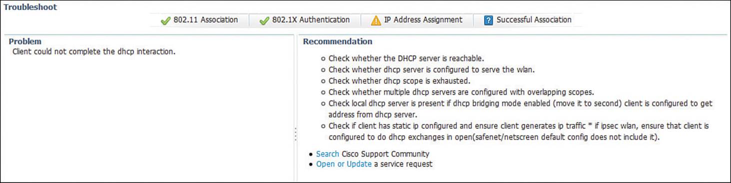
Figure 20-12 Displaying the Results of Client Troubleshooting Tests
Troubleshooting Clients from the Controller
Prime Infrastructure offers a “single pane of glass” interface into wireless networks by communicating with and gathering information from the wireless controllers. You can perform quite a bit of troubleshooting directly through the controller GUI and CLI too—much of it the same as from PI. This section presents a summary of the controller-based troubleshooting knowledge required for the CCNA Wireless exam.
As a wireless client probes and attempts to associate with an AP, it is essentially communicating with the controller. You can access a wealth of troubleshooting information from the controller, as long as you know the client’s MAC address.
You can view a client’s current status by navigating to Monitor > Clients. The controller will display every client that is associated to any of its APs. To find a specific client in the long list of clients, click the Change Filter link. You can then filter the list based on MAC address, AP name, WLAN profile or SSID, client status, client radio type, and so on. In Figure 20-13, the list will be filtered to display only client MAC address 00:15:70:f2:1c:c1.
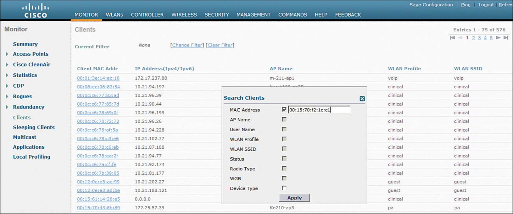
Figure 20-13 Displaying and Filtering Client Status Information on a Controller
Click the client MAC address link to display all the detailed information known about the client. The information that is shown is very similar to the client details that Prime Infrastructure shows, including client statistics, the client’s policy manager state, security parameters, and RF readings.
You can also select the blue arrow icon at the right end of the client entry to display a drop-down menu to manage the client’s association, as shown in Figure 20-14. Selecting Remove will deauthenticate the client and force it off the network, so that it will attempt to associate again. Selecting Disable will add the client’s MAC address to the list of disabled clients and will force the client off the network.
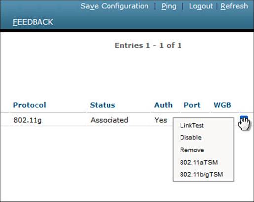
Figure 20-14 Managing a Client Association
Verifying Client WLAN Settings
If an end user reports a problem connecting to the wireless network, you should verify that the client device has been configured with wireless settings that match those of the WLAN. If the two do not match, then the association will fail.
First, view the wireless connection settings on the client and look for the SSID and the wireless security parameters. Figure 20-15 shows example parameters on a Windows 7 machine that were displayed by right-clicking the wireless connection and selecting Properties. The client has been configured for SSID “clinical” using WPA2 Enterprise, AES encryption, and Microsoft PEAP authentication. The controller’s WLAN settings are shown in Figure 20-16. The controller has been configured for SSID clinical using WPA2, AES encryption, and pre-shared key (PSK) authentication. It is the mismatch between WPA2 authentication schemes that is preventing the client from connecting.
![]()
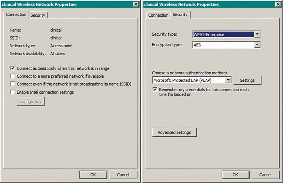
Figure 20-15 Displaying WLAN Settings on a Windows 7 Client
![]()
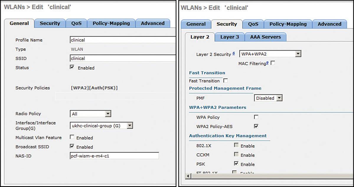
Figure 20-16 Displaying WLAN Settings on a Controller for Comparison with Client Settings
Tip
If a client cannot associate after you exhaust your attempts at troubleshooting, be aware that the client may be listed in the controller as an excluded or disabled client. A client can be added to the exclusion list automatically, when the client’s activity matches one of the controller’s wireless protection policy signatures. A client can also be moved to the disabled clients list manually, usually as a result of violating a local security policy. Navigate to Security > Disabled Clients and look for the client’s MAC address in the list. If the list is long, you can also use the search tool to search for the MAC address on that page.
Viewing Controller Logs
A wireless LAN controller maintains two types of logs that can be useful for troubleshooting:
![]() A trap log, which records events such as detected rogue devices, AP changes, channel changes, and invalid settings
A trap log, which records events such as detected rogue devices, AP changes, channel changes, and invalid settings
![]() A message log, which contains system conditions for the controller as a whole
A message log, which contains system conditions for the controller as a whole
You can view the logs with the controller GUI and the CLI. Table 20-3 lists the menus and commands needed to display the log contents in either management interface.
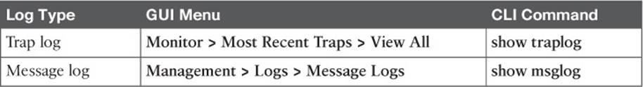
Table 20-3 Methods to Display Controller Log Contents
Troubleshooting AP Connectivity
In cases where you get reports from multiple users who are all having problems in the same general area, you might need to focus your efforts on an AP. The problem could be as simple as a defective radio, where no clients are receiving a signal. In that case, you might have to go onsite to confirm that the transmitter is not working correctly.
Otherwise, the split-MAC architecture creates several different points where you can troubleshoot. Recall the Cisco unified wireless network structure illustrated in Figure 20-17. To successfully operate the lightweight AP (LAP) and provide a working BSS, the following two things must work correctly:
![]() The LAP must have connectivity to its access layer switch.
The LAP must have connectivity to its access layer switch.
![]() The LAP must have connectivity to its WLC.
The LAP must have connectivity to its WLC.
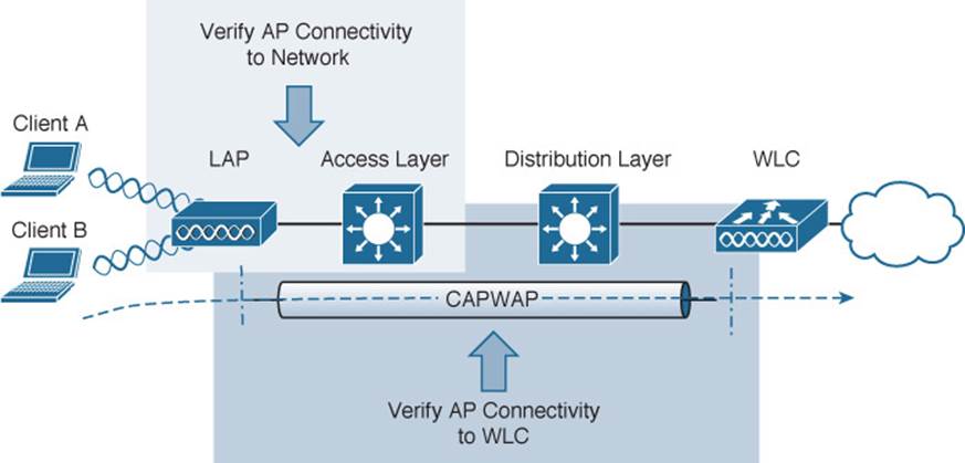
Figure 20-17 Verifying AP Connectivity in a Cisco Unified Wireless Network
Verifying AP-to-WLC Connectivity
First, verify the connectivity between an AP and a controller. Usually you will do this when a new AP is installed, to make sure it is able to discover and join a controller before clients arrive and try to use the wireless network. You can also do this at any time as a quick check of the AP’s health.
The easiest approach is to simply look for the AP in the list of live APs that have joined the controller. If you know which controller the AP should join, open a management session to it. Navigate to Wireless > All APs > Change Filter, and then enter the AP’s MAC address or some portion of its name. If the search reveals a live AP that is joined to the controller, verify the IP address that the AP is using and make sure that the AP Uptime shows a valid working duration, as shown in Figure 20-18.
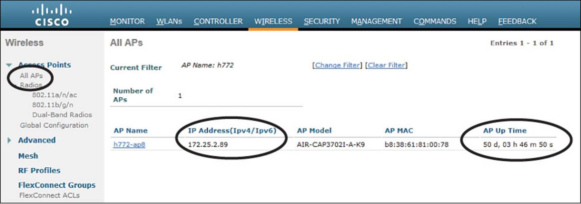
Figure 20-18 Verifying That an AP Is Alive
As long as the controller shows the AP with an appropriate IP address, you can assume that there is a working CAPWAP tunnel between the two. If clients are reporting problems with one SSID that they have in common, you should review the WLAN configuration on the controller to make sure it is bound to the correct controller interface and to the correct VLAN.
If your network is large and you have many controllers, you might not know which one the AP has joined. You can look from a more broad perspective by searching for the AP in PI.
Verifying AP-to-Network Connectivity
If you do not find the AP joined to a controller, you will have to move your focus further away from the controller and onto the AP and its wired connection.
Before an AP can boot up and operate correctly, it must have a power source. Most likely, an AP gets its power from the access layer switch as Power over Ethernet (PoE) over the Ethernet cabling. The more radios an AP supports, the more power it can consume. Therefore, different AP models can require different amounts of power. You should verify the minimum PoE requirements of an AP and compare that with the PoE capability of the switch.
The 802.3af standard specifies that a PoE switch can provide up to 15.4 watts to a PoE device. Switch ports using the 802.3at standard can offer up to 30 watts PoE on an interface. When you look for the AP power requirements, be sure that the required power includes all radios in operation.
Once the AP has sufficient power, does it have an IP address? Without the help of a controller, you might have to connect to the AP console and watch the logging information scroll by as the AP tries to boot, get an address, and find a controller to join. You can also query the DHCP server to see whether the AP has an active address lease. If it is not able to get an address from a DHCP server, check the address scope on the server to ensure that the address space is not exhausted.
Tip
To connect to the CLI of an AP, you need to enter some credentials. By default, log in with username Cisco and password Cisco. The default enable secret password is also Cisco.
If the AP is having trouble joining a controller, verify that the switch port configuration where the AP is connected. A lightweight AP needs only a single VLAN to support the CAPWAP tunnel. All WLANs are transported over the tunnel without the need for separate VLANs. In contrast, an autonomous AP has no CAPWAP tunnel, so it needs a trunk link that can carry individual WLANs over VLANs. The switch port configuration should look like one of those shown in Table 20-4.
![]()
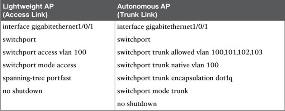
Table 20-4 Switch Port Configuration to Support an AP
Finally, recall that a lightweight AP tries a variety of methods to discover viable controllers to join. A common method is to configure a DHCP server to send DHCP option 43 with lease offers to APs. Option 43 is a string of hex digits that contains the IP addresses of one or more controllers. The DHCP server might not have option 43 configured at all, or it could have a typo or error in the hex string.
Sometimes you might connect an AP and wait a very long time for it to join a controller, only to find that it does not. First, check the controller licensing to make sure that there are enough available licenses for the AP. If you still cannot figure out what the AP is doing, you can connect directly to its console port and watch the logging information scroll by as the AP attempts to discover controllers.
The console output listed in Example 20-1 shows that the AP is not able to obtain an IP address so it can join the wired network. In Example 20-2, the AP picked up a list of three candidate controller IP addresses (192.168.90.22, 192.168.90.23, and 192.168.90.16) from the DHCP server. However, the AP then tries to initiate a Datagram Transport Layer Security (DTLS) tunnel (part of CAPWAP) to a controller known as m7-c1 at address 172.22.253.17, and successfully joins it. Perhaps this AP was previously configured with a primary controller address elsewhere before it was installed on the network. Therefore, it used an unexpected controller address.
Example 20-1 AP Console Output Showing an IP Address Problem
*Mar 1 00:13:33.515: %CDP_PD-4-POWER_OK: Full power - INJECTOR_DETECTED_PD inline
ccpower source
*Mar 1 00:13:34.537: %LINK-3-UPDOWN: Interface Dot11Radio1, changed state to up
*Mar 1 00:13:35.537: %LINEPROTO-5-UPDOWN: Line protocol on Interface Dot11Radio1,
changed state to up
*Mar 1 00:13:35.563: %LINK-3-UPDOWN: Interface Dot11Radio0, changed state to up
*Mar 1 00:13:36.563: %LINEPROTO-5-UPDOWN: Line protocol on Interface Dot11Radio0,
changed state to up
*Mar 1 00:13:57.962: %CAPWAP-3-ERRORLOG: Not sending discovery request AP does not
have an Ip !!
*Mar 1 00:14:17.962: %CAPWAP-3-ERRORLOG: Not sending discovery request AP does not
have an Ip !!
Example 20-2 Verifying Candidate Controller Addresses from the AP Console
*Mar 1 00:16:18.971: %CAPWAP-5-DHCP_OPTION_43: Controller address 192.168.90.22
obtained through DHCP
*Mar 1 00:16:18.971: %CAPWAP-5-DHCP_OPTION_43: Controller address 192.168.90.23
obtained through DHCP
*Mar 1 00:16:18.971: %CAPWAP-5-DHCP_OPTION_43: Controller address 192.168.90.16
obtained through DHCP
*Mar 1 00:16:19.012: %CAPWAP-3-ERRORLOG: Could Not resolve CISCO-CAPWAP-CONTROLLER
*Mar 1 00:16:29.020: %CAPWAP-3-ERRORLOG: Selected MWAR m7-c1'(index 0).
*Mar 1 00:16:29.020: %CAPWAP-3-ERRORLOG: Go join a capwap controller
*Sep 12 14:16:04.000: %CAPWAP-5-DTLSREQSEND: DTLS connection request sent peer_ip:
172.22.253.17 peer_port: 5246
*Sep 12 14:16:04.791: %CAPWAP-5-DTLSREQSUCC: DTLS connection created successfully
peer_ip: 172.22.253.17 peer_port: 5246
*Sep 12 14:16:04.792: %CAPWAP-5-SENDJOIN: sending Join Request to 172.22.253.17
*Sep 12 14:16:05.069: %LINK-3-UPDOWN: Interface Dot11Radio0, changed state to down
*Sep 12 14:16:05.108: %LINK-5-CHANGED: Interface Dot11Radio0, changed state to reset
*Sep 12 14:16:05.117: %CAPWAP-5-JOINEDCONTROLLER: AP has joined controller m7-c1
Verifying the AP and Antenna Orientation
Suppose you have verified that an AP is working properly and has joined a controller, but users near the AP still report connectivity issues. You might consider looking at the AP to make sure it has been mounted properly so that the RF coverage works as designed. If the AP has external antennas, make sure that the antennas are oriented appropriately.
Indoor AP models such as the Cisco Aironet 3702i, 2702i, and 1702i are designed to be mounted flat against a ceiling. The small omnidirectional antennas inside the AP case are oriented such that the RF signal will be dispersed slightly downward and away from the AP in all directions. That simply means the AP can cover the most floor area when it is mounted facedown and flat against the ceiling.
If you find that an AP with internal antennas has been mounted on a wall, the antennas will be oriented perpendicular to the wall. This causes the RF signals to be dispersed along the wall in all directions, effectively ruining the broad floor coverage the AP should have had.
APs with external antennas, such as the Cisco Aironet 3702e and 2702e, have antennas that protrude and can be easily reoriented. Even when an AP is installed with its antennas oriented correctly, someone may come along and knock the antennas if they are within reach. If that happens, you may never know about the reduced coverage until a wireless user calls to complain. To correctly orient the antennas of a wall-mounted AP, turn the top two antennas facing straight up, the bottom two facing straight down, the center left facing left, and the center right facing right—all parallel with the wall.
Checking the RF Environment
To investigate problems that could involve things like 802.11 traffic, client roaming, RF interference, or co-channel or adjacent channel interference, you might need to leverage some third-party tools. The CCNA Wireless exam blueprint lists several topics related to a variety of tools. You should not need to know how to install and use the tools, but you should know which tools are useful for specific scenarios.
The operating systems on common Windows- and Mac OS X–based wireless client devices offer some basic utilities that you can use to display all of the SSIDs that are being broadcast or advertised. As Figure 20-19 shows, the list of SSIDs is handy when you need to select and connect to one, but is of limited value if you need to troubleshoot a problem. The utility does show each SSID and a bar-like indicator of the APs’ signal strengths.
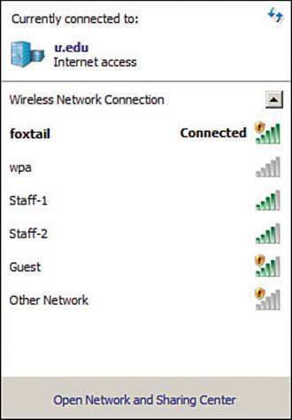
Figure 20-19 Using a Client OS–based Utility to List Available SSIDs
Wi-Fi scanning tools are more useful for quick scans and walkthrough surveys of an area, to see all of the active APs and their channel use. Typical examples are MetaGeek inSSIDer Office, Android Wifi Analyzer, and Fluke AirMagnet WiFi Analyzer, shown in Figures 20-20 through 20-22. The MetaGeek inSSIDer Office and Android Wifi Analyzer tools both scan all 2.4- and 5-GHz channels and display any SSIDs overheard on each. You can also see BSSID information that contains the SSID name, AP MAC address, wireless security settings, RSSI, and channel number used. At a glance, you can detect channel overlap and gauge co-channel and adjacent channel interference. For example, if you see two instances of the same SSID on the same channel, it is easy to check the signal strength separation to make sure that the modulation and coding schemes will operate correctly.
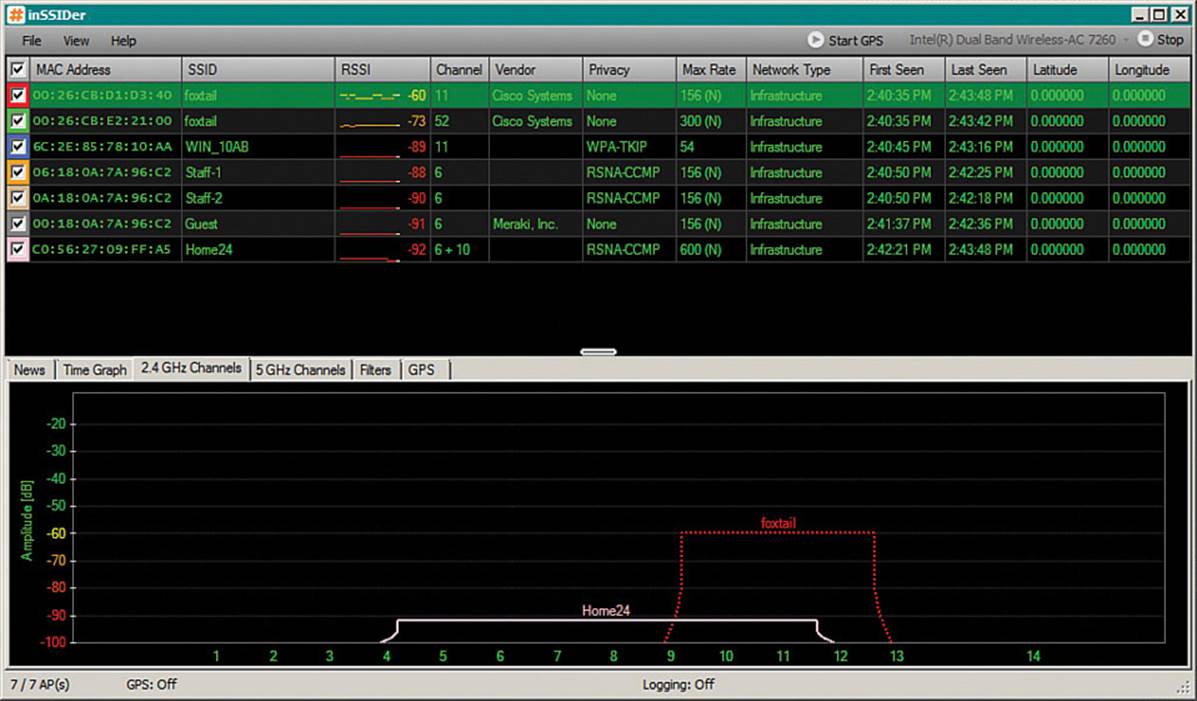
Figure 20-20 Scanning Channels with MetaGeek inSSIDer Office
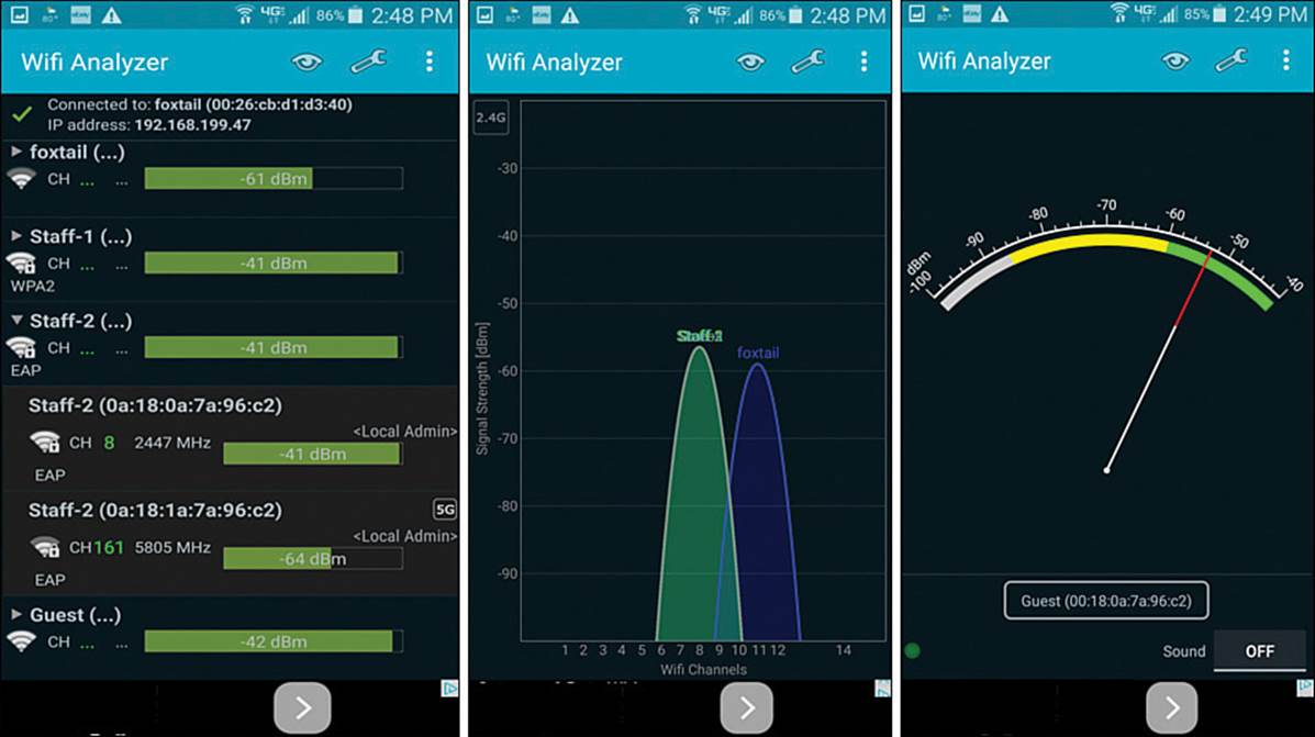
Figure 20-21 Scanning Channels with Android Wifi Analyzer
Fluke AirMagnet WiFi Analyzer, shown in Figure 20-22, can also scan channels and display SSIDs and BSSIDs. It can also do much, much more. WiFi Analyzer is a robust tool that scans all channels and performs many types of analysis on the transmissions that are received. It also offers “expert” advice about conditions that are detected.
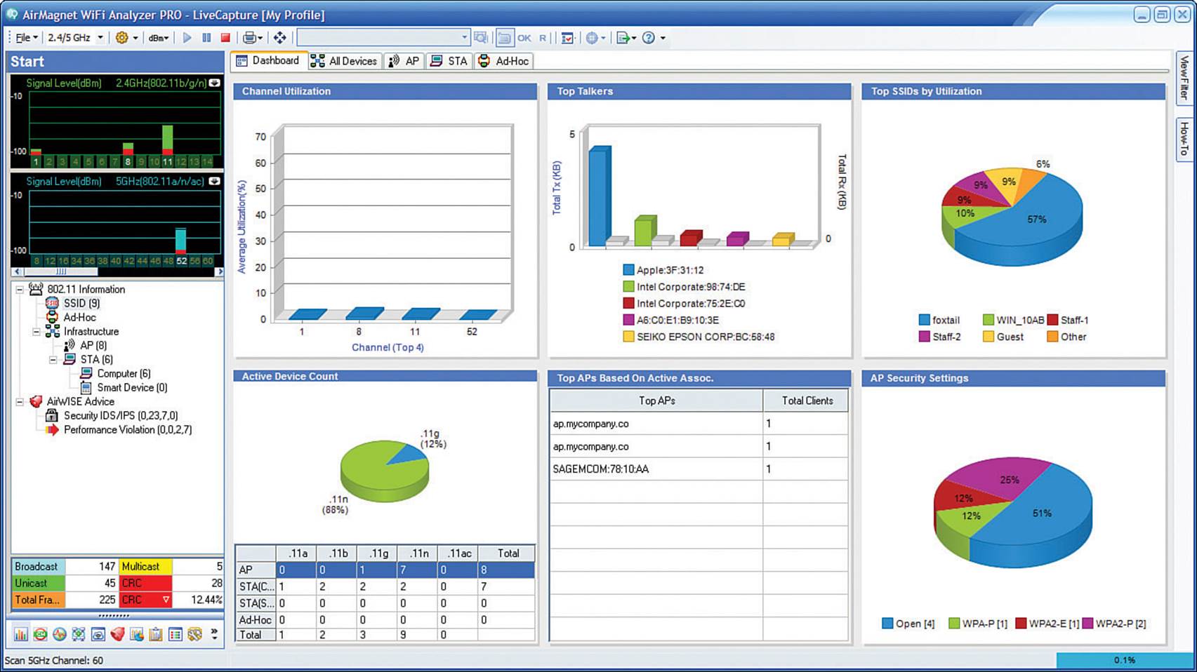
Figure 20-22 Analyzing Wi-Fi Activity with Fluke AirMagnet WiFi Analyzer
You can leverage a wireless packet analyzer such as Savvius OmniPeek or Wireshark to capture 802.11 frames and decode the contents for further analysis. Because packet analyzers can interpret the contents of wireless frames and their payloads (assuming the frames do not use a strong encryption), they are most useful when you need to troubleshoot low-level problems between devices. For example, you can capture wireless data to see exactly how a client device is communicating with an AP, how a client handles a roaming condition, how the quality of a voice call is being handled, and so on. Figure 20-23 shows an example of an OmniPeek wireless capture and analysis.
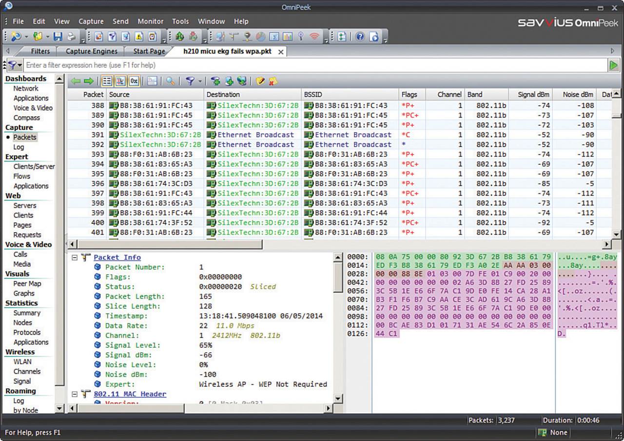
Figure 20-23 Analyzing Wi-Fi Frames Captured Over the Air with Savvius OmniPeek
You might also need to leverage third-party RF mapping tools to perform site surveys, where RF signal strength, SNR, and many other parameters are measured over an area and displayed on spatial maps. RF mapping tools are covered in greater detail in Chapter 7, “Planning Coverage with Wireless APs.”
Spectrum analyzers are special-purpose tools that you can use to measure RF energy across a range of frequencies, to detect the presence of 802.11 APs and many types of interfering sources. Spectrum analysis is covered in greater detail in Chapter 19, “Dealing with Wireless Interference.”
Table 20-5 provides a summary of typical applications of third-party tools, their common uses, and examples of tools and vendors.
![]()
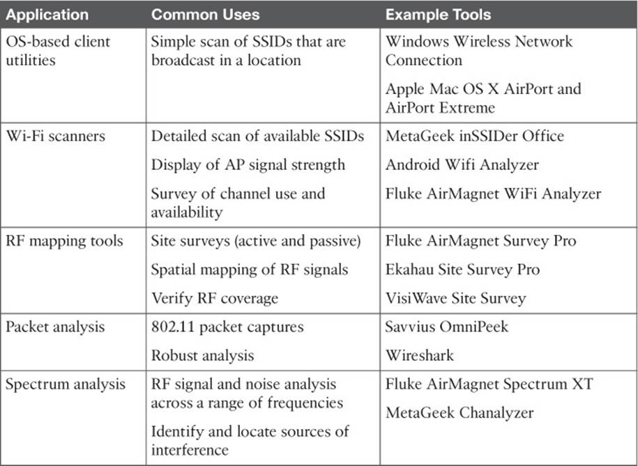
Table 20-5 Third-Party Wireless Troubleshooting Tools
Exam Preparation Tasks
As mentioned in the section, “How to Use This Book,” in the Introduction, you have a couple of choices for exam preparation: the exercises here, Chapter 21, “Final Review,” and the exam simulation questions on the DVD.
Review All Key Topics
Review the most important topics in this chapter, noted with the Key Topic icon in the outer margin of the page. Table 20-6 lists a reference of these key topics and the page numbers on which each is found.
![]()
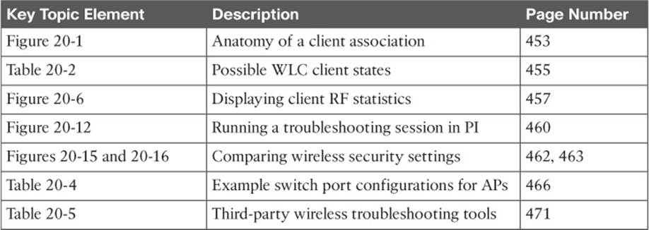
Table 20-6 Key Topics for Chapter 20
All materials on the site are licensed Creative Commons Attribution-Sharealike 3.0 Unported CC BY-SA 3.0 & GNU Free Documentation License (GFDL)
If you are the copyright holder of any material contained on our site and intend to remove it, please contact our site administrator for approval.
© 2016-2026 All site design rights belong to S.Y.A.