CCNP Routing and Switching TSHOOT 300-135 Official Cert Guide (2015)
Part III. Troubleshooting Router Features
Chapter 9. Troubleshooting IPv4 Addressing and Addressing Technologies
This chapter covers the following topics:
![]() Troubleshooting IPv4 Addressing: This section focuses on how you can verify that devices are addressed correctly in the network during your troubleshooting process.
Troubleshooting IPv4 Addressing: This section focuses on how you can verify that devices are addressed correctly in the network during your troubleshooting process.
![]() Troubleshooting DHCP for IPv4: This section reviews the DHCP for IPv4 operations and identifies how you can successfully troubleshoot DHCP related issues.
Troubleshooting DHCP for IPv4: This section reviews the DHCP for IPv4 operations and identifies how you can successfully troubleshoot DHCP related issues.
![]() Troubleshooting NAT: This section explains the reasons why NAT may not be translating addresses and how to recognize them.
Troubleshooting NAT: This section explains the reasons why NAT may not be translating addresses and how to recognize them.
![]() IPv4 Addressing and Addressing Technologies Trouble Tickets: This section provides trouble tickets that demonstrate how you can use a structured troubleshooting process to solve a reported problem.
IPv4 Addressing and Addressing Technologies Trouble Tickets: This section provides trouble tickets that demonstrate how you can use a structured troubleshooting process to solve a reported problem.
Although IPv6 is currently being deployed, it is being done at a slow pace. Therefore, most networks are still relying on IPv4, and many new networks and network additions are being deployed with IPv4. Therefore, as a troubleshooter, you need the skills necessary to successfully identify issues related to improper IPv4 addressing on devices. It might be a bad address, subnet mask, or even the address of the default gateway.
Typically, when deploying IPv4 addresses, Dynamic Host Configuration Protocol (DHCP) will be used so that they can be dynamically assigned. However, with this dynamic process, issues may arise that prevent a device from successfully obtaining an IPv4 address from the DHCP server. Therefore, you need a solid understanding of how DHCP operates and how to identify the issues that would prevent a client from obtaining an IP address from a DHCP server.
Because RFC 1918 addresses are not routable on the Internet, Network Address Translation (NAT) is needed to translate IPv4 private addresses to public addresses that are routable on the Internet. This adds another bit of complexity to the environment that you need to know how to troubleshoot so that devices can access resources external to the organization.
This chapter covers the different methods that you can use to troubleshoot IPv4 addressing issues, DHCP for IPv4-related issues, and NAT issues.
“Do I Know This Already?” Quiz
The “Do I Know This Already?” quiz allows you to assess whether you should read this entire chapter thoroughly or jump to the “Exam Preparation Tasks” section. If you are in doubt about your answers to these questions or your own assessment of your knowledge of the topics, read the entire chapter. Table 9-1 lists the major headings in this chapter and their corresponding “Do I Know This Already?” quiz questions. You can find the answers in Appendix A, “Answers to the ‘Do I Know This Already?’ Quizzes.”
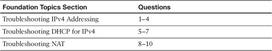
Table 9-1 “Do I Know This Already?” Section-to-Question Mapping
Caution
The goal of self-assessment is to gauge your mastery of the topics in this chapter. If you do not know the answer to a question or are only partially sure of the answer, you should mark that question as wrong for purposes of the self-assessment. Giving yourself credit for an answer that you correctly guess skews your self-assessment results and might provide you with a false sense of security.
1. What will occur when a PC with the IP address 10.1.1.27/28 needs to communicate with a PC that has an IP address of 10.1.1.18? (Choose two answers.)
a. It will send the frame to its default gateway.
b. It will send the frame directly to the destination PC.
c. It will ARP for the MAC address of the default gateway.
d. It will ARP for the MAC address of the destination PC.
2. What will occur when a PC with the IP address 10.1.1.27/29 needs to communicate with a PC that has an IP address of 10.1.1.18? (Choose two answers.)
a. It will send the frame to its default gateway.
b. It will send the frame directly to the destination PC.
c. It will ARP for the MAC address of the default gateway.
d. It will ARP for the MAC address of the destination PC.
3. Which command enables you to verify the IP address configured on a Windows PC interface?
a. ipconfig
b. show ip interface
c. arp -a
d. show ip arp
4. Which command enables you to verify the IP address configured on a router’s interface?
a. ipconfig
b. show ip interface
c. arp -a
d. show ip arp
5. What is the correct order of operations for the DHCP for IPv4 process?
a. Offer, Request, Ack, Discover
b. Discover, Request, Ack, Offer
c. Request, Offer, Discover, Ack
d. Discover, Offer, Request, Ack
6. Which command is needed on a router interface to forward DHCP Discover messages to a DHCP server on a different subnet?
a. ip address dhcp
b. ip helper-address
c. ip dhcp-forwarder
d. ip dhcp server
7. Which command will enable a router interface to obtain an IP address from a DHCP server?
a. ip dhcp client
b. ip dhcp server
c. ip address dhcp
d. ip helper-address
8. Which parameter is necessary in the ip nat inside source command to enable PAT?
a. pat
b. list
c. overload
d. private
9. Which command enables you to verify the interfaces that are configured for NAT?
a. show ip nat translations
b. show ip nat statistics
c. show ip nat interfaces
d. show ip nat
10. Which column in the output of show ip nat translations displays the address that source IPs have been translated to?
a. Inside Local
b. Inside Global
c. Outside Local
d. Outside Global
Foundation Topics
Troubleshooting IPv4 Addressing
Just like your personal street address uniquely defines where you live, an IPv4 address uniquely defines where a device resides in a network. Your street address is made of two parts, the street name and the number of your residence; and the combination of these will be unique within your city/town. As a result, the pizza delivery person is able to drop off your pizza at your house in 30 minutes or it is free. If your house is addressed incorrectly, you may or may not get your pizza, and we do not want that to happen.
The same is true with IPv4 addressing. If devices are addressed incorrectly, they may or may not receive the packets that are intended for them. Therefore, it is imperative that you have a solid understanding of IPv4 addressing and how to verify that devices are addressed correctly on the network.
This section focuses on how we can troubleshoot IPv4 addressing issues.
IPv4 Addressing Issues
An IPv4 address is made up of two parts: a network/subnet portion and a host portion. It is imperative that all devices in the same network/subnet share the exact same network/subnet portion. If they are not exactly the same, the PC could end up addressing the Layer 2 frame incorrectly and sending the packet in the wrong direction. Refer to Figure 9-1, which shows a sample subnet (10.1.1.0/26) with two PCs and their default gateway, R1.

Figure 9-1 Correct IPv4 Addressing Example

When PC1 needs to communicate with PC2, it does a DNS lookup for the IP address of PC2. The IP address 10.1.1.20 is returned. Now PC1 needs to determine whether PC2 is located in the same subnet because this will determine whether the frame will have the MAC of PC2 or the MAC of the default gateway (DG). PC1 determines its network/subnet portion by comparing its IP address to its subnet mask in binary as follows:
00001010.00000001.00000001.00001010 – PC1 IP address in binary
11111111.11111111.11111111.11000000 – PC1 subnet mask in binary
-----------------------------------
00001010.00000001.00000001.00 – PC1 network/subnet ID
(The 1s in the subnet mask identify the network portion.)
Now PC1 compares the exact same binary bits to those binary bits in PC2’s address as follows:
00001010.00000001.00000001.00 – PC1 network/subnet ID
00001010.00000001.00000001.00010100 – PC2 IP address in binary
Because the binary bits are the same, PC1 concludes that PC2 is in the same network/subnet; therefore, it can communicate directly with it and does not need to send the data to its default gateway. PC1 will create a frame with its own source MAC address and the MAC of PC2 as the destination.
Consider what occurs when PC1 needs to communicate with the web server at 192.0.2.1. It does a DNS lookup for the IP address of the web server. The IP address 192.0.2.1 is returned. Now PC1 needs to determine whether the web server is located in the same network/subnet. This will determine whether the frame will have the MAC of the web server or the MAC of the DG. PC1 determines its network/subnet portion by comparing its IP address to its subnet mask in binary as follows:
00001010.00000001.00000001.00001010 – PC1 IP address in binary
11111111.11111111.11111111.11000000 – PC1 subnet mask in binary
-----------------------------------
00001010.00000001.00000001.00 – PC1 network/subnet ID
(The 1s in the subnet mask identify the network portion.)
Now PC1 compares the exact same binary bits to those binary bits in the web server address as follows:
00001010.00000001.00000001.00 – PC1 network/subnet ID
11000000.00000000.00000010.00000001 – web server IP address in binary
PC1 concludes that the web server is in a different network/subnet, because the bits are not the same; therefore, to communicate with the web server, it needs to send the data to its default gateway. PC1 will create a frame with its own source MAC address and the MAC of R1 as the destination.
As you can see, accurate IP addressing is paramount for successful communication. Let’s see what happens if PC1 is configured with the wrong subnet mask (255.255.255.240), as shown in Figure 9-2.
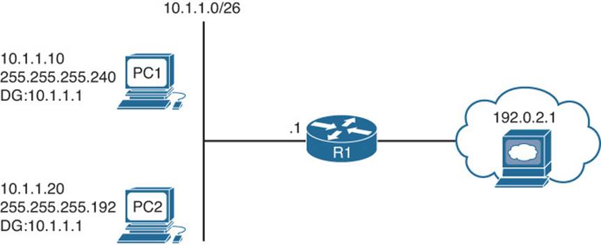
Figure 9-2 Incorrect IPv4 Addressing Example
PC1 determines its network/subnet portion by comparing its IP address to its subnet mask in binary as follows:
00001010.00000001.00000001.00001010 – PC1 IP address in binary
11111111.11111111.11111111.11110000 – PC1 subnet mask in binary
---------------------------------------------------
00001010.00000001.00000001.0000 – PC1 network/subnet ID
Now PC1 compares the exact same binary bits to those binary bits in PC2s address as follows:
00001010.00000001.00000001.0000 – PC1 network/subnet ID
00001010.00000001.00000001.00010100 – PC2 IP address in binary
PC1 concludes that PC2 is not in the same network/subnet, because the binary bits are not exactly the same. Therefore, it cannot communicate directly with it and will need to send the frame to the router so that the router can route the packet to the subnet PC2 is in. However, the PCs are actually connected to the same subnet, and as a result we have an IPv4 addressing and connectivity issue.
Not only will an improper subnet mask cause issues, but an inappropriate IP address combined with the correct subnet mask will also cause issues. In addition, if the default gateway is not configured correctly on the PCs, packets will not be forwarded to the correct device when packets need to be sent to a different subnet.
As a troubleshooter, you need to be able to recognize these issues, or eliminate them as a possible issue quickly. You can verify the IP addressing information on a Windows PC using the ipconfig command and on a router or switch using the show ip interface interface_type interface_number command, as shown in Example 9-1.
Example 9-1 Verifying IP Addressing on a PC and on a Router
C:\>ipconfig
Windows IP Configuration
Ethernet adapter PC1:
Connection-specific DNS Suffix . :
IP Address. . . . . . . . . . . . : 10.1.1.10
Subnet Mask . . . . . . . . . . . : 255.255.255.192
IP Address. . . . . . . . . . . . : 2001:10::10
IP Address. . . . . . . . . . . . : fe80::a00:27ff:fe5d:6d6%4
Default Gateway . . . . . . . . . : 10.1.1.1
R1#show ip interface gigabitEthernet 1/0
GigabitEthernet1/0 is up, line protocol is up
Internet address is 10.1.1.1/26
...output omitted..
Determining IP Addresses Within a Subnet
You want to be quick! Here is a quick way to determine all the IP addresses that will be in a particular subnet. Refer to Figure 9-3 as you are exploring this method.
Figure 9-3 Determining IP Address Within a Subnet
Take the subnet mask and find the most interesting octet. This is where the last binary 1 would be. In this case, 255.255.255.192 would have the last binary 1 in the fourth octet, which is 192.
Now, take 256 and subtract 192 from it. The result is 64. The number 64 represents the block size or the total number of addresses in that subnet. Our subnet in this case is 10.1.1.0/26, and because the block size is 64, this subnet would begin at 10.1.1.0/26 and end at 10.1.1.63/26, which is a total of 64 addresses. The next subnet would be 10.1.1.64/26 to 10.1.1.127/26. The third subnet would be 10.1.1.128/26 to 10.1.1.191/26 and so on.
Now you can compare the addresses of devices with the subnet ranges you just identified. In this case, PC1, PC2, and an interface on R1 are supposed to be in the same subnet. As a result, they better all be addressed correctly or communication will not occur correctly. For example, if you are reviewing the output of ipconfig on PC1, as shown in Example 9-2, now that you have the ranges, you can easily see that PC1 is not in the same subnet as R1 and PC2. Although they have the same subnet mask, in this case PC1 falls in the range 10.1.1.64/26 to 10.1.1.127/26, whereas PC2 and the default gateway fall in the range 10.1.1.0/26 to 10.1.1.63/26. PC1 is in a different network/subnet, when it should be in the same according to Figure 9-3. You will have to fix the address on PC1 so that it is within the correct network/subnet.
Example 9-2 Verifying IP Addressing on PC with the ipconfig Command
C:\>ipconfig
Windows IP Configuration
Ethernet adapter PC1:
Connection-specific DNS Suffix . :
IP Address. . . . . . . . . . . . : 10.1.1.74
Subnet Mask . . . . . . . . . . . : 255.255.255.192
IP Address. . . . . . . . . . . . : 2001:10::10
IP Address. . . . . . . . . . . . : fe80::a00:27ff:fe5d:6d6%4
Default Gateway . . . . . . . . . : 10.1.1.1
Troubleshooting DHCP for IPv4
Dynamic Host Configuration Protocol (DHCP) serves as one of the most common methods of assigning IPv4 address information to a network host. Specifically, DHCP allows a DHCP client to obtain an IP address, subnet mask, default gateway IP address, DNS server IP address, and other types of IP address information from a DHCP server. The DHCP server can be local within the subnet, in a remote subnet, or the same device that is also the default gateway.
Because it is the most common way to deploy IPv4 addresses, you need to be well versed in the DHCP process and able to recognize issues related to DHCP. This section explains how DHCP operates and focuses on how to identify DHCP-related issues.
Reviewing DHCP Operations
If you have a cable modem, digital subscriber line (DSL), or fiber connection in your home, your router more than likely obtains its IP address from your service provider via DHCP. The router is also acting as a DHCP server for the devices in your home. In corporate networks, when a PC boots, that PC receives its IP address configuration information from a corporate DHCP server. Figure 9-4 illustrates the exchange of messages (Discover, Offer, Request, Acknowledgment [DORA] process) that occur as a DHCP client obtains IP address information from a DHCP server.
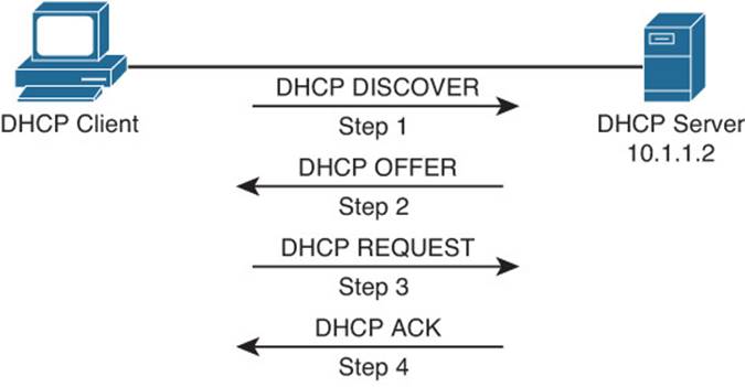
Figure 9-4 DHCP DORA Process
Step 1. When a DHCP client initially boots, it has no IP address, default gateway, or other such configuration information. Therefore, the way a DHCP client initially communicates is by sending a broadcast message (that is, a DHCPDISCOVER message) to a destination IP address of 255.255.255.255 and a destination MAC address of FFFF:FFFF:FFFF in an attempt to discover a DHCP server. The source IP address will be 0.0.0.0, and the source MAC address will be the MAC address of the sending device.
Step 2. When a DHCP server receives a DHCPDISCOVER message, it can respond with a DHCPOFFER message with an unleased IP address, subnet mask, and default gateway information. Because the DHCPDISCOVER message is sent as a broadcast, more than one DHCP server might respond to this Discover message with a DHCPOFFER. However, the client typically selects the server that sent the first DHCPOFFER response it received.
Step 3. The DHCP client communicates with the selected server by sending a broadcasted DHCPREQUEST message indicating that it will be using the address provided in the DHCPOFFER and as a result wants the associated address leased to itself.
Step 4. Finally, the DHCP server responds to the client with a DHCPACK message indicating that the IP address is leased to the client and includes any additional DHCP options that might be needed at this point.
Notice that in Step 1 the DHCPDISCOVER message was sent as a broadcast. The broadcast cannot cross a router boundary. Therefore, if a client resides on a different network than the DHCP server, the default gateway of the client should be configured as a DHCP relay agent to forward the broadcast packets as unicast packets to the server. You can use the ip helper-address ip_address interface configuration mode command to configure a router to relay DHCP messages to a DHCP server in the organization.
To illustrate, consider Figure 9-5 and Example 9-3. In the figure, the DHCP client belongs to the 172.16.1.0/24 network, whereas the DHCP server belongs to the 10.1.1.0/24 network. Router R1 is configured as a DHCP relay agent by using the syntax shown in Example 9-3.
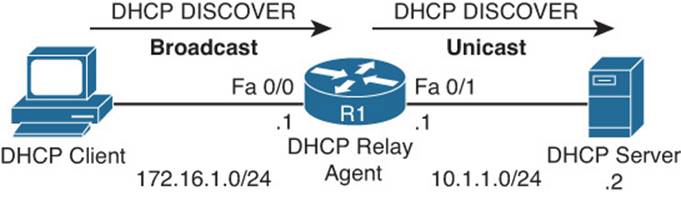
Figure 9-5 DHCP Relay Agent
Example 9-3 DHCP Relay Agent Configuration
R1#configure terminal
Enter configuration commands, one per line. End with CNTL/Z.
R1(config)#service dhcp
R1(config)#interface fa 0/0
R1(config-if)#ip helper-address 10.1.1.2
In the configuration, notice the service dhcp command. This command enables the DHCP service on the router, which must be enabled for the DHCP services to function. This command is usually not required because the DHCP service is enabled by default; however, when troubleshooting a DHCP relay agent issue, you might want to confirm that the service is enabled. Also, the ip helper-address 10.1.1.2 command specifies the IP address of the DHCP server. If the wrong IP address is specified, the DHCP messages will be relayed to the wrong device. In addition, the ip helper-address command must be configured on the interface that is receiving the DHCPDISCOVER messages from the clients. If not, the router cannot relay the DHCP messages.
When you configure a router to act as a DHCP relay agent, realize that it relays a few other broadcast types in addition to a DHCP message. Other protocols that are forwarded by a DHCP relay agent include the following:
![]() TFTP
TFTP
![]() Domain Name System (DNS)
Domain Name System (DNS)
![]() Internet Time Service (ITS)
Internet Time Service (ITS)
![]() NetBIOS name server
NetBIOS name server
![]() NetBIOS datagram server
NetBIOS datagram server
![]() BootP
BootP
![]() TACACS
TACACS
As a reference, Table 9-2 provides a comprehensive listing of DHCP message types you might encounter while troubleshooting a DHCP issue.
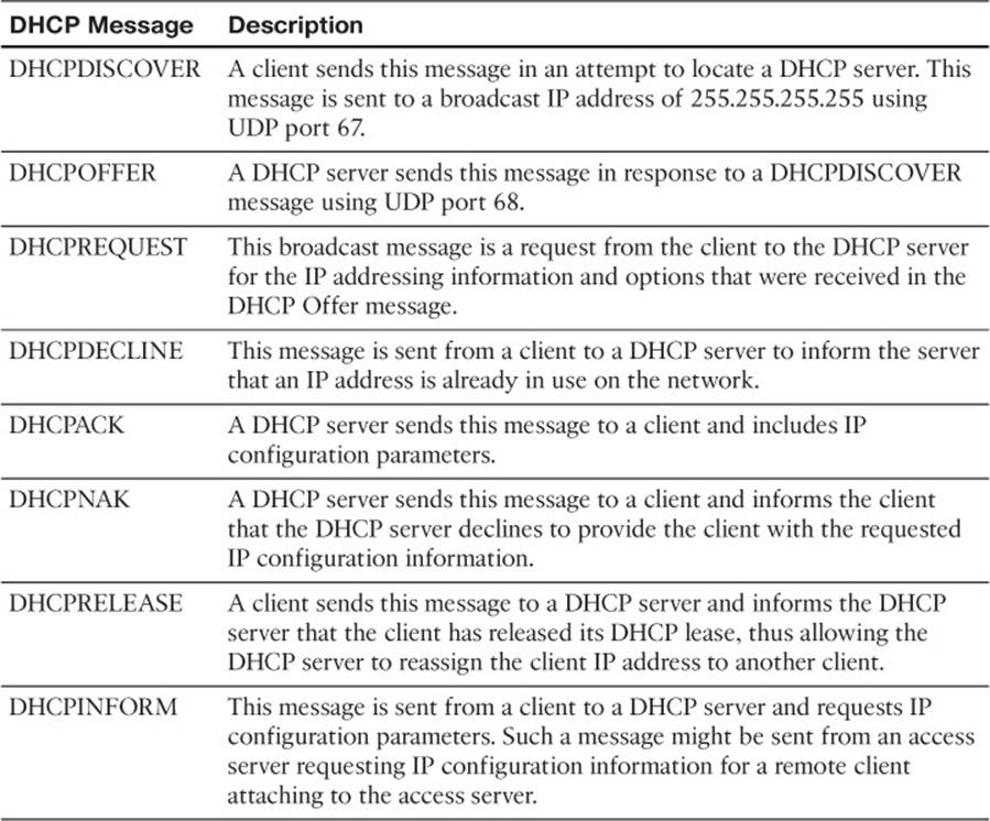
Table 9-2 DHCP Message Types
In addition to acting as a DHCP relay agent, a router might act as a DHCP client. Specifically, the interface of a router might obtain its IP address from a DHCP server. Figure 9-6 shows a router acting as a DHCP client, where the router’s Fast Ethernet 0/1 interface obtains its IP address from a DHCP server. Example 9-4 provides the configuration for the router in the topology (that is, router R1). Notice the dhcp option used in the ip address command, instead of the usual IP address and subnet mask information.
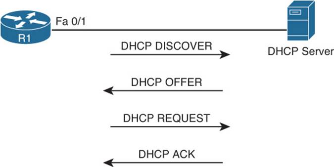
Figure 9-6 Router Acting as a DHCP Client
Example 9-4 DHCP Client Configuration
R1#configure terminal
R1(config)#int fa 0/1
R1(config-if)#ip address dhcp
A router and multilayer switch can also act as a DHCP server. Figure 9-7 shows a router acting as a DHCP server, and Example 9-5 shows the router configuration. The ip dhcp excluded-address 10.8.8.1 10.8.8.10 command prevents DHCP from assigning those IP addresses to a client. Note that you do not have to include the IP address of the router interface in this exclusion because the router will never hand out its own interface IP address. The ip dhcp pool POOL-A command creates a DHCP pool named POOL-A. This pool can hand out IP addresses from the 10.8.8.0/24 network, with a default gateway of 10.8.8.1, a DNS server of 192.168.1.1, and a WINS server of 192.168.1.2.
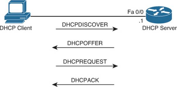
Figure 9-7 Router Acting as a DHCP Server
Example 9-5 DHCP Server Configuration
R1#show run
...OUTPUT OMITTED...
ip dhcp excluded-address 10.8.8.1 10.8.8.10
!
ip dhcp pool POOL-A
network 10.8.8.0 255.255.255.0
default-router 10.8.8.1
dns-server 192.168.1.1
netbios-name-server 192.168.1.2
...OUTPUT OMITTED...
If your device is configured to receive an IP address from a DHCP server but the IP address of the client is an APIPA (Automatic Private IP Addressing) address (169.254.x.x) because of autoconfiguration, as shown in Example 9-6, you can conclude that the client was not able to obtain an IP address from the DHCP server. Do not immediately assume that DHCP is the problem. It is quite possible that you have a Layer 2 problem, such as VLANs, trunks, Spanning Tree Protocol (STP), or security, for example, that is preventing the clients DHCPDISCOVER message from reaching the DHCP server.
Example 9-6 Verifying DHCP-Assigned IP Address on PC
C:\>ipconfig /all
Windows IP Configuration
...output omitted...
Ethernet adapter PC1 Lab:
Connection-specific DNS Suffix . :
Description . . . . . . . . . . . : AMD PCNET Family PCI Ethernet Adapter
Physical Address. . . . . . . . . : 08-00-27-5D-06-D6
Dhcp Enabled. . . . . . . . . . . : Yes
Autoconfiguration Enabled . . . . : Yes
Autoconfiguration IP Address. . . : 169.254.180.166
Subnet Mask . . . . . . . . . . . : 255.255.0.0
IP Address. . . . . . . . . . . . : 2001:10::10
IP Address. . . . . . . . . . . . : fe80::a00:27ff:fe5d:6d6%4
Default Gateway . . . . . . . . . :
Potential DHCP Troubleshooting Issues
When troubleshooting what you suspect might be a DHCP issue, consider the following potential issues:
![]() A router not forwarding broadcasts: By default, a router does not forward broadcasts, including DHCPDISCOVER broadcast messages. Therefore, a router needs to be explicitly configured to act as a DHCP relay agent if the DHCP client and DHCP server are on different subnets.
A router not forwarding broadcasts: By default, a router does not forward broadcasts, including DHCPDISCOVER broadcast messages. Therefore, a router needs to be explicitly configured to act as a DHCP relay agent if the DHCP client and DHCP server are on different subnets.
![]() DHCP pool out of IP addresses: A DHCP pool contains a finite number of addresses. Once a DCHP pool becomes depleted, new DHCP requests are rejected.
DHCP pool out of IP addresses: A DHCP pool contains a finite number of addresses. Once a DCHP pool becomes depleted, new DHCP requests are rejected.
![]() Misconfiguration: The configuration of a DHCP server might be incorrect. For example, the range of network addresses to be given out by a particular pool might be incorrect, or the exclusion of addresses statically assigned to routers or DNS servers might be incorrect.
Misconfiguration: The configuration of a DHCP server might be incorrect. For example, the range of network addresses to be given out by a particular pool might be incorrect, or the exclusion of addresses statically assigned to routers or DNS servers might be incorrect.
![]() Duplicate IP addresses: A DHCP server might hand out an IP address to a client that is already statically assigned to another host on the network. These duplicate IP addresses can cause connectivity issues for both the DHCP client and the host that had been statically configured for the IP address.
Duplicate IP addresses: A DHCP server might hand out an IP address to a client that is already statically assigned to another host on the network. These duplicate IP addresses can cause connectivity issues for both the DHCP client and the host that had been statically configured for the IP address.
![]() Redundant services not communicating: Some DHCP servers can coexist with other DHCP servers for redundancy. For this redundancy to function, these DHCP servers need to communicate with one another. If this interserver communication fails, the DHCP servers can hand out overlapping IP addresses to their clients.
Redundant services not communicating: Some DHCP servers can coexist with other DHCP servers for redundancy. For this redundancy to function, these DHCP servers need to communicate with one another. If this interserver communication fails, the DHCP servers can hand out overlapping IP addresses to their clients.
![]() The “pull” nature of DHCP: When a DHCP client wants an IP address, it can request an IP address from a DHCP server. However, the DHCP server has no ability to initiate a change in the client IP address after the client obtains an IP address. In other words, the DHCP client pulls information from the DHCP server, but the DHCP server cannot push information to the DHCP client.
The “pull” nature of DHCP: When a DHCP client wants an IP address, it can request an IP address from a DHCP server. However, the DHCP server has no ability to initiate a change in the client IP address after the client obtains an IP address. In other words, the DHCP client pulls information from the DHCP server, but the DHCP server cannot push information to the DHCP client.
![]() Interface not configured with IP address in DHCP pool: A router or a multilayer switch that is acting as a DHCP server must have an interface with an IP address that is part of the pool/subnet that it is handing out IP addresses for. The router will only hand the addresses in the pool to clients reachable out that interface. This ensures that the router interface and the clients are in the same subnet. However, note that this is not the case if a relay agent is forwarding DHCP messages between the client and the router that is the DHCP server. In that case, the DHCP server does not have to have an IP address on an interface that is part of the pool it is handing out addresses for.
Interface not configured with IP address in DHCP pool: A router or a multilayer switch that is acting as a DHCP server must have an interface with an IP address that is part of the pool/subnet that it is handing out IP addresses for. The router will only hand the addresses in the pool to clients reachable out that interface. This ensures that the router interface and the clients are in the same subnet. However, note that this is not the case if a relay agent is forwarding DHCP messages between the client and the router that is the DHCP server. In that case, the DHCP server does not have to have an IP address on an interface that is part of the pool it is handing out addresses for.
At this point in this section, you have reviewed basic DHCP operations and potential DHCP troubleshooting targets. When you begin your troubleshooting efforts, you might want to collect the following information to help you better isolate the underlying cause of the DHCP issue you are investigating:
![]() The configuration of the DHCP server: For example, confirm that the pools are correctly defined with appropriate network addresses, default gateways, and other relevant IP address information.
The configuration of the DHCP server: For example, confirm that the pools are correctly defined with appropriate network addresses, default gateways, and other relevant IP address information.
![]() The configuration of the DHCP relay agent: For example, ensure that the specified helper address is the correct unicast IP address and ensure that it is configured on the interface on which DHCPDISCOVER broadcasts will be received.
The configuration of the DHCP relay agent: For example, ensure that the specified helper address is the correct unicast IP address and ensure that it is configured on the interface on which DHCPDISCOVER broadcasts will be received.
![]() Determine the size of a DHCP pool: Because a pool in a DHCP server accommodates only a limited number of IP addresses, determine how many IP addresses (if any) are still available from a given DHCP pool.
Determine the size of a DHCP pool: Because a pool in a DHCP server accommodates only a limited number of IP addresses, determine how many IP addresses (if any) are still available from a given DHCP pool.
![]() Verify IP address of router interface: If the router is a DHCP server (and there is no relay agent configured to forward DHCP messages to it), verify that the router has the correct IP address assigned to the correct interface based on the pools it will be handing out addresses for. If the interface does not have an IP address that is part of a pool it is handing out addresses for, it will not hand out addresses to the clients out the interface it is receiving DHCPDISCOVER messages on.
Verify IP address of router interface: If the router is a DHCP server (and there is no relay agent configured to forward DHCP messages to it), verify that the router has the correct IP address assigned to the correct interface based on the pools it will be handing out addresses for. If the interface does not have an IP address that is part of a pool it is handing out addresses for, it will not hand out addresses to the clients out the interface it is receiving DHCPDISCOVER messages on.
DHCP Troubleshooting Commands
Example 9-7 provides sample output from the show ip dhcp conflict command. The output indicates a duplicate 172.16.1.3 IP address on the network, which the router discovered via a ping. You can clear the information displayed by issuing the clear ip dhcp conflict * command after you have resolved the duplicate address issue on the network.
Example 9-7 show ip dhcp conflict Command Output
R1#show ip dhcp conflict
IP address Detection method Detection time
172.16.1.3 Ping Oct 15 2014 8:56 PM
Example 9-8 shows sample output from the show ip dhcp binding command. The output indicates that an IP address of 10.1.1.10 was assigned to a DHCP client. You can release this DHCP lease with the clear ip dhcp binding * command.
Example 9-8 show ip dhcp binding Command Output
R1#show ip dhcp binding
Bindings from all pools not associated with VRF:
IP address Client-ID/ Lease expiration Type
Hardware address/
User name
10.1.1.3 0100.50b6.0765.7a Oct 17 2014 07:53 PM Automatic
10.1.1.10 0108.0027.5d06.d6 Oct 17 2014 07:53 PM Automatic
Example 9-9 shows sample output from the debug ip dhcp server events command. The output shows updates to the DHCP database.
Example 9-9 debug ip dhcp server events Command Output
R1#debug ip dhcp server events
DHCPD: Seeing if there is an internally specified pool class:
DHCPD: htype 1 chaddr c001.0f1c.0000
DHCPD: remote id 020a00000a01010101000000
DHCPD: circuit id 00000000
DHCPD: Seeing if there is an internally specified pool class:
DHCPD: htype 1 chaddr c001.0f1c.0000
DHCPD: remote id 020a00000a01010101000000
DHCPD: circuit id 00000000
DHCPD: no subnet configured for 192.168.1.238.
Example 9-10 shows sample output from the debug ip dhcp server packet command. The output shows a DHCPRELEASE message being received when a DHCP client with an IP address of 10.1.1.3 is shut down. You can also see the four-step process of a DHCP client obtaining an IP address of 10.1.1.4 with the following messages: DHCPDISCOVER, DHCPOFFER, DHCPREQUEST, and DHCPACK.
Example 9-10 debug ip dhcp server packet Command Output
R1#debug ip dhcp server packet
DHCPD: DHCPRELEASE message received from client
0063.6973.636f.2d63.3030.312e.3066.3163.2e30.3030.302d.4661.302f.30 (10.1.1.3).
DHCPD: DHCPRELEASE message received from client
0063.6973.636f.2d63.3030.312e.3066.3163.2e30.3030.302d.4661.302f.30 (10.1.1.3).
DHCPD: Finding a relay for client
0063.6973.636f.2d63.3030.312e.3066.3163.2e30.3030.302d.4661.302f.30 on interface
FastEthernet0/1.
DHCPD: DHCPDISCOVER received from client
0063.6973.636f.2d63.3030.312e.3066.3163.2e30.3030.302d.4661.302f.30 on interface
FastEthernet0/1.
DHCPD: Allocate an address without class information
(10.1.1.0)
DHCPD: Sending DHCPOFFER to client
0063.6973.636f.2d63.3030.312e.3066.3163.2e30.3030.302d.4661.302f.30 (10.1.1.4).
DHCPD: broadcasting BOOTREPLY to client c001.0f1c.0000.
DHCPD: DHCPREQUEST received from client
0063.6973.636f.2d63.3030.312e.3066.3163.2e30.3030.302d.4661.302f.30.
DHCPD: No default domain to append - abort update
DHCPD: Sending DHCPACK to client
0063.6973.636f.2d63.3030.312e.3066.3163.2e30.3030.302d.4661.302f.30 (10.1.1.4).
DHCPD: broadcasting BOOTREPLY to client c001.0f1c.0000.
Troubleshooting NAT
In IPv4 networks, Network Address Translation (NAT) is needed for multiple reasons. However, the most common reason is to translate a private IPv4 address to a public IPv4 address. This section explains how NAT operates and identifies NAT related issues and how to troubleshoot them.
Reviewing NAT
Public IP addresses are routable through the public Internet, whereas private IP addresses (as defined in RFC 1918) are not, and are intended for use within an organization. Because devices within an organization using private IP addresses need to communicate outside of their local networks (Internet/public network), NAT is needed to translate the private IP addresses into Internet-routable IP addresses (that is, public IP addresses). Table 9-3 identifies three types of NAT.
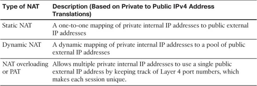
Table 9-3 Types of NAT
Consider Figure 9-8, which shows a basic NAT topology. In the topology, a client with a private IP address of 10.1.1.10 wants to communicate with a server on the public Internet at 192.0.2.1. Router R1 is configured for NAT. Router R1 takes packets coming from 10.1.1.10 that are destined for remote devices (such as the server) and changes the source IP address in the packet headers to 203.0.113.1, which is a publicly routable IP address. When the server at IP address 192.0.2.1 receives traffic from the client, the return traffic from the server is sent to a destination address of 203.0.113.1. When router R1 receives traffic from the outside network destined for 203.0.113.1, the router translates the destination IP address to 10.1.1.10 and forwards the traffic to the inside network, where the client receives the traffic.
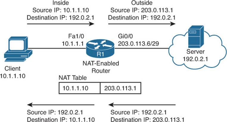
Figure 9-8 Basic NAT Topology Example
Note that NAT by itself does not scale well for an organization that has many privately addressed devices that need access to the public Internet all at the same time. As you can see from the example just discussed, you would need one public IP for every single private IP you want to translate. To overcome this issue, you use Port Address Translation (PAT), which can translate multiple private IP addresses to the same public IP address by keeping track of port numbers. PAT is simply a feature that NAT provides. Figure 9-9 displays how PAT can use port numbers and have multiple private IPs use the same public IP address. In this case, the public IP address is the same one that is used on the outside interface; however, you could also use a pool of public addresses. When the packet sourced from IP 10.1.1.10 port 65500 arrives at the PAT-enabled router, it translates it to the appropriate public IP and makes note of the port number as well as the IP address in the NAT table. Therefore, when traffic returns from the server destined to 203.0.113.1 port 65500, the router knows it is destined for 10.1.1.10 at port 65500. The client at 10.1.1.20 will also be translated to the same outside IP address, but a different port number will be used. This ensures that the router can differentiate between the different packets and who they are truly sourced from and destined to.
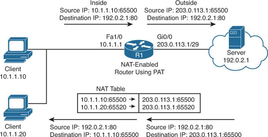
Figure 9-9 Basic PAT Topology Example
To effectively troubleshoot a NAT configuration, you should be familiar with the terminology describing the various IP addresses involved in a translation, as outlined in Table 9-4.
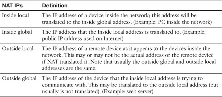
Table 9-4 Names of NAT IP Addresses
Based on the definitions in Table 9-4, Table 9-5 categorizes the IP addresses previously shown in Figure 9-9.
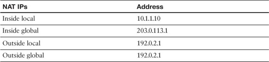
Table 9-5 Classifying the NAT IP Addresses in Figure 9-9
NAT Troubleshooting Issues
Refer to Example 9-11, which displays a sample NAT/PAT configuration that uses a pool of public addresses. Notice how many different issues could arise based on a mistake in the configuration.
![]() Interfaces not configured correctly: You need to specify which interfaces will be the outside and inside interfaces. If not configured correctly, NAT will not translate addresses properly.
Interfaces not configured correctly: You need to specify which interfaces will be the outside and inside interfaces. If not configured correctly, NAT will not translate addresses properly.
![]() The pool may be misconfigured: The pool must specify the correct public addresses that will be translated. This pool represents the inside global addresses.
The pool may be misconfigured: The pool must specify the correct public addresses that will be translated. This pool represents the inside global addresses.
![]() The public addresses in the pool are not reachable: For traffic to return from the destination, the public addresses need to be reachable (advertised) to the Internet.
The public addresses in the pool are not reachable: For traffic to return from the destination, the public addresses need to be reachable (advertised) to the Internet.
![]() The access list may not reference the correct inside devices: The ACL identifies the inside local addresses that will be translated to inside global addresses. If the ACL is incorrect, addresses will not be translated correctly.
The access list may not reference the correct inside devices: The ACL identifies the inside local addresses that will be translated to inside global addresses. If the ACL is incorrect, addresses will not be translated correctly.
![]() ACL and pool not mapped correctly: The ip nat inside source command marries the ACL and the pool together. If this mapping is incorrect, NAT will not translate addresses correctly.
ACL and pool not mapped correctly: The ip nat inside source command marries the ACL and the pool together. If this mapping is incorrect, NAT will not translate addresses correctly.
![]() Overload keyword missing: To enable PAT, the overload keyword must be included in the ip nat inside source command.
Overload keyword missing: To enable PAT, the overload keyword must be included in the ip nat inside source command.
Example 9-11 Dynamic NAT with PAT Sample Configuration
R1#show run
...OUTPUT OMITTED...
interface FastEthernet1/0
ip address 10.1.1.1 255.255.255.0
ip nat inside
!
interface GigabitEthernet 0/0
ip address 203.0.113.1 255.255.255.248
ip nat outside
!
ip nat pool OUTSIDE_POOL 203.0.113.3 203.0.113.6 netmask 255.255.255.248
ip nat inside source list 1 pool OUTSIDE_POOL overload
!
access-list 1 permit 10.1.1.0 0.0.0.255
...OUTPUT OMITTED...
From a troubleshooting perspective, adding NAT into a network introduces additional troubleshooting issues. Consider the following situations in which NAT might cause an issue for end users:
![]() Using NAT over a VPN: Some VPN protocols check the checksum of a packet to verify its integrity. The checksum calculated for a packet before NAT differs from a checksum calculated for that same packet after NAT (because performing NAT on a packet changes IP address information). Therefore, a virtual private network (VPN) protocol (for example, IPsec) might reject such a packet because it appears to have been altered.
Using NAT over a VPN: Some VPN protocols check the checksum of a packet to verify its integrity. The checksum calculated for a packet before NAT differs from a checksum calculated for that same packet after NAT (because performing NAT on a packet changes IP address information). Therefore, a virtual private network (VPN) protocol (for example, IPsec) might reject such a packet because it appears to have been altered.
![]() NAT hiding true IP address information: Because NAT translates an inside IP address to an outside IP address, tracing a data flow from end to end for troubleshooting purposes can be challenging. You can start troubleshooting by using the show ip nat translation command to verify whether the translation does exist in the translation table.
NAT hiding true IP address information: Because NAT translates an inside IP address to an outside IP address, tracing a data flow from end to end for troubleshooting purposes can be challenging. You can start troubleshooting by using the show ip nat translation command to verify whether the translation does exist in the translation table.
![]() Applications that are not NAT compatible: When some applications initialize, they randomly determine what ports are going to be used for communication, which might be incompatible with how NAT handles incoming traffic. Some Voice over IP (VoIP) protocols face such an issue, as they select the User Datagram Protocol (UDP) port numbers to be used for their Real-time Transport Protocol (RTP) media streams. Also, when setting up communication with a remote device, an application might include IP address information in the payload of a packet. If the remote device attempted to return traffic to the IP address embedded in that payload, that IP address might be unreachable because of the NAT translation.
Applications that are not NAT compatible: When some applications initialize, they randomly determine what ports are going to be used for communication, which might be incompatible with how NAT handles incoming traffic. Some Voice over IP (VoIP) protocols face such an issue, as they select the User Datagram Protocol (UDP) port numbers to be used for their Real-time Transport Protocol (RTP) media streams. Also, when setting up communication with a remote device, an application might include IP address information in the payload of a packet. If the remote device attempted to return traffic to the IP address embedded in that payload, that IP address might be unreachable because of the NAT translation.
![]() Delays experienced due to NAT’s processing: Because NAT manipulates Layer 3 information of packets, the packets are subject to a bit more delay than they would otherwise experience. This delay might become more evident on routers performing numerous NAT translations.
Delays experienced due to NAT’s processing: Because NAT manipulates Layer 3 information of packets, the packets are subject to a bit more delay than they would otherwise experience. This delay might become more evident on routers performing numerous NAT translations.
NAT Troubleshooting Commands
Example 9-12 provides sample output from the show ip nat translations command and how to clear all dynamic entries in this output with the clear ip nat translation * command. Initially, the show ip nat translations command shows three statically configured NAT translations and one dynamically learned translation (which is highlighted in the output). Then, after issuing the clear ip nat translation * command, the dynamically learned NAT entry is deleted from the IP NAT table, leaving the three statically configured NAT entries.
Example 9-12 show ip nat translations and clear ip nat translation * Command Output
Router#show ip nat translations
Pro Inside global Inside local Outside local Outside global
--- 192.168.1.12 192.168.0.1 --- ---
--- 192.168.1.13 192.168.0.2 --- ---
tcp 192.168.1.27:23 192.168.0.27:23 192.168.1.50:1158 192.168.1.50:1158
--- 192.168.1.27 192.168.0.27 --- ---
Router#clear ip nat translation *
Router#show ip nat translations
Pro Inside global Inside local Outside local Outside global
--- 192.168.1.12 192.168.0.1 --- ---
--- 192.168.1.13 192.168.0.2 --- ---
--- 192.168.1.27 192.168.0.27 --- ---
Example 9-13 provides sample output from the show ip nat statistics command. The output shows which interfaces are acting as the inside and outside interfaces, and it shows the current number of static and dynamic translations.
Example 9-13 show ip nat statistics Command Output
R1#show ip nat statistics
Total active translations: 4 (3 static, 1 dynamic; 1 extended)
Outside interfaces:
FastEthernet0/0
Inside interfaces:
FastEthernet0/1
Hits: 10 Misses: 0
CEF Translated packets: 5, CEF Punted packets: 0
Expired translations: 0
Dynamic mappings:
Appl doors: 0
Normal doors: 0
Queued Packets: 0
Example 9-14 provides sample output from the debug ip nat command, which you should use with caution because it can crash a router. The output shows that when a source IP address of 192.168.1.50 is attempting to communicate with a destination IP address of 192.168.1.27, the router translates the destination IP address into 192.168.0.27. Also, when a source IP address of 192.168.1.11 is attempting to communicate with a destination IP address of 192.168.1.50, the router translates the source IP address of 192.168.1.11 into an IP address of 192.168.1.27.
Example 9-14 debug ip nat Command Output
R1#debug ip nat
IP NAT debugging is on
NAT*: s=192.168.1.50, d=192.168.1.27->192.168.0.27 [10202]
NAT: s=192.168.1.11->192.168.1.27, d=192.168.1.50 [210]
NAT*: s=192.168.1.50, d=192.168.1.27->192.168.0.27 [10370]
NAT: s=192.168.1.11->192.168.1.27, d=192.168.1.50 [211]
NAT*: s=192.168.1.50, d=192.168.1.27->192.168.0.27 [10540]
NAT: s=192.168.1.11->192.168.1.27, d=192.168.1.50 [214]
IPv4 Addressing and Addressing Technologies Trouble Tickets
This section presents various trouble tickets relating to the topics discussed earlier in the chapter. The purpose of these trouble tickets is to give a process that you can follow when troubleshooting in the real world or in an exam environment. All trouble tickets in this section are based on the topology depicted in Figure 9-10.
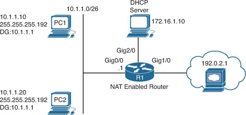
Figure 9-10 IPv4 Addressing Trouble Tickets Topology
Trouble Ticket 9-1
Problem: PC1 is not able to access resources on the web server 192.0.2.1.
You begin troubleshooting by verifying the issue with a ping from PC1 to 192.0.2.1. As shown in Example 9-15, the ping fails.
Example 9-15 Failed Ping from PC1 to 192.0.2.1
C:\PC1>ping 192.0.2.1
Pinging 192.0.2.1 with 32 bytes of data:
Request timed out.
Request timed out.
Request timed out.
Request timed out.
Ping statistics for 192.0.2.1:
Packets: Sent = 4, Received = 0, Lost = 4 (100% loss),
Next you ping the default gateway for PC1, which is R1, at 10.1.1.1. As shown in Example 9-16, the ping is successful.
Example 9-16 Successful Ping from PC1 to Default Gateway
C:\PC1>ping 10.1.1.1
Reply from 10.1.1.1: bytes=32 time 1ms TTL=128
Reply from 10.1.1.1: bytes=32 time 1ms TTL=128
Reply from 10.1.1.1: bytes=32 time 1ms TTL=128
Reply from 10.1.1.1: bytes=32 time 1ms TTL=128
Ping statistics for 10.1.1.1:
Packets: Sent = 4, Received = 4, Lost = 0 (0% loss),
Approximate round trip times in milli-seconds:
Minimum = 0ms, Maximum = 0ms, Average = 0ms
You decide to see whether this is an isolated incident. You access PC2 and ping 192.0.2.1, which is successful, as shown in Example 9-17.
Example 9-17 Successful Ping from PC2 to 192.0.2.1
C:\PC2>ping 192.0.2.1
Reply from 192.0.2.1: bytes=32 time 1ms TTL=128
Reply from 192.0.2.1: bytes=32 time 1ms TTL=128
Reply from 192.0.2.1: bytes=32 time 1ms TTL=128
Reply from 192.0.2.1: bytes=32 time 1ms TTL=128
Ping statistics for 192.0.2.1:
Packets: Sent = 4, Received = 4, Lost = 0 (0% loss),
Approximate round trip times in milli-seconds:
Minimum = 0ms, Maximum = 0ms, Average = 0ms
At this point, you have determined that Layer 2 and Layer 3 connectivity from PC1 and PC2 to the router is fine. You also confirmed that PC2 can reach Internet resources even though PC1 cannot. There are many reasons why this situation might exist. One of the big ones is an ACL on Gig0/0 or Gig1/0 that is denying PC1 from accessing resources on the Internet. It could also be a NAT issue that is preventing 10.1.1.10 from being translated. However, before we go down that path, review the basics. For example, what about the default gateway configured on PC1? If it is configured incorrectly, PC1 is sending packets that are destined to a remote subnet to the wrong default gateway. Reviewing the output of ipconfig on PC1, as shown in Example 9-18, indicates that the default gateway is configured as 10.1.1.100, which is not the IP address of R1s interface.
Example 9-18 ipconfig Output on PC1
C:\PC1>ipconfig
Windows IP Configuration
Ethernet adapter Local Area Connection:
Connection-specific DNS Suffix . :
IP Address. . . . . . . . . . . . : 10.1.1.10
Subnet Mask . . . . . . . . . . . : 255.255.255.192
Default Gateway . . . . . . . . . : 10.1.1.100
After you change the default gateway on R1 to 10.1.1.1, the ping to 192.0.2.1 is successful, as shown in Example 9-19.
Example 9-19 Successful Ping from PC1 to 192.0.2.1
C:\PC1>ping 192.0.2.1
Reply from 192.0.2.1: bytes=32 time 1ms TTL=128
Reply from 192.0.2.1: bytes=32 time 1ms TTL=128
Reply from 192.0.2.1: bytes=32 time 1ms TTL=128
Reply from 192.0.2.1: bytes=32 time 1ms TTL=128
Ping statistics for 192.0.2.1:
Packets: Sent = 4, Received = 4, Lost = 0 (0% loss),
Approximate round trip times in milli-seconds:
Minimum = 0ms, Maximum = 0ms, Average = 0ms
Trouble Ticket 9-2
Problem: PC1 is not able to access resources on the web server 192.0.2.1.
You begin troubleshooting by verifying the issue with a ping from PC1 to 192.0.2.1. As shown in Example 9-20, the ping fails.
Example 9-20 Failed Ping from PC1 to 192.0.2.1
C:\PC1>ping 192.0.2.1
Pinging 192.0.2.1 with 32 bytes of data:
Request timed out.
Request timed out.
Request timed out.
Request timed out.
Ping statistics for 192.0.2.1:
Packets: Sent = 4, Received = 0, Lost = 4 (100% loss),
Next you ping the default gateway for PC1, which is R1, at 10.1.1.1. As shown in Example 9-21, it fails as well.
Example 9-21 Failed Ping from PC1 to Default Gateway
C:\PC1>ping 10.1.1.1
Pinging 10.1.1.1 with 32 bytes of data:
Request timed out.
Request timed out.
Request timed out.
Request timed out.
Ping statistics for 10.1.1.1:
Packets: Sent = 4, Received = 0, Lost = 4 (100% loss),
Next you decide to see whether this is an isolated incident by pinging from PC2 to the IP address 192.0.2.1 and to the default gateway at 10.1.1.1. As shown in Example 9-22, both pings fail as well, indicating that it is not isolated.
Example 9-22 Failed Ping from PC2 to 192.0.2.1 and Default Gateway
C:\PC2>ping 192.0.2.1
Pinging 192.0.2.1 with 32 bytes of data:
Request timed out.
Request timed out.
Request timed out.
Request timed out.
Ping statistics for 192.0.2.1:
Packets: Sent = 4, Received = 0, Lost = 4 (100% loss),
C:\PC2>ping 10.1.1.1
Pinging 10.1.1.1 with 32 bytes of data:
Request timed out.
Request timed out.
Request timed out.
Request timed out.
Ping statistics for 10.1.1.1:
Packets: Sent = 4, Received = 0, Lost = 4 (100% loss),
At this point, you have confirmed that there is no Layer 2 or Layer 3 connectivity from PC1 or PC2 to their default gateway. As you have seen in previous chapters, this can be caused by many different reasons. For example, VLANs, VACLs, trunks, VTP, STP, are all possible reasons why this issue is occurring. However, always remember to check the basics first: IP addressing on the client. On PC1, you issue the ipconfig command, and as shown in Example 9-23, PC1 has an APIPA (Automatic Private IP Addressing) address of 169.254.180.166/16 and no default gateway. This means that PC1 cannot contact a DHCP server and is autoconfiguring an IP address. This still does not rule out a VLAN, trunk, VTP, STP, and so on. However, it is helping us narrow the focus.
Example 9-23 ipconfig Output on PC1
C:\PC1>ipconfig
Windows IP Configuration
Ethernet adapter Local Area Connection:
Connection-specific DNS Suffix . :
IP Address. . . . . . . . . . . . : 169.254.180.166
Subnet Mask . . . . . . . . . . . : 255.255.0.0
Default Gateway . . . . . . . . . :
We can clearly see in the trouble ticket topology in Figure 9-10 that the DHCP server is located out interface Gig2/0 on R1. It is in a different subnet than the PCs. Therefore, R1 is required to forward the DHCPDISCOVER messages from the PCs to the DHCP server at 172.16.1.10. To do this, it needs the ip helper-address command configured on Gig0/0. Let’s start there so that we can eliminate this as the issue and focus elsewhere if need be. On R1, you issue the command show run interface gig 0/0, as shown in Example 9-24. The output indicates that the IP helper address is 172.16.1.100, which is not correct according to the network diagram.
Example 9-24 Verifying the IP Helper Address on Gig0/0 of R1
R1#show run interface gigabitEthernet 0/0
Building configuration...
Current configuration : 193 bytes
!
interface GigabitEthernet0/0
ip address 10.1.1.1 255.255.255.192
ip helper-address 172.16.1.100
ip nat inside
end
After you fix the IP helper address with the no ip helper-address 172.16.1.100 command and issue the ip helper-address 172.16.1.10 command in interface configuration mode, PC1 successfully receives IP addressing information from the DHCP server, as shown in Example 9-25.
Example 9-25 R1 with Correct IP Addressing After Fixing the IP Helper Address Command
C:\PC1>ipconfig
Windows IP Configuration
Ethernet adapter Local Area Connection:
Connection-specific DNS Suffix . :
IP Address. . . . . . . . . . . . : 10.1.1.10
Subnet Mask . . . . . . . . . . . : 255.255.255.192
Default Gateway . . . . . . . . . : 10.1.1.1
After you verify the addressing information on R1, the ping to 192.0.2.1 is successful, as shown in Example 9-26.
Example 9-26 Successful Ping from PC1 to 192.0.2.1
C:\PC1>ping 192.0.2.1
Reply from 192.0.2.1: bytes=32 time 1ms TTL=128
Reply from 192.0.2.1: bytes=32 time 1ms TTL=128
Reply from 192.0.2.1: bytes=32 time 1ms TTL=128
Reply from 192.0.2.1: bytes=32 time 1ms TTL=128
Ping statistics for 192.0.2.1:
Packets: Sent = 4, Received = 4, Lost = 0 (0% loss),
Approximate round trip times in milli-seconds:
Minimum = 0ms, Maximum = 0ms, Average = 0ms
Trouble Ticket 9-3
Problem: No PC in the 10.1.1.0 network can access resources on the Internet. You suspect NAT is the issue. As shown in Example 9-27, there are no translations occurring when you look at the output of show ip nat translations.
Example 9-27 Viewing the NAT Translations on R1
R1#show ip nat translations
R1#
In Example 9-28, you issue the show ip nat statistics command on R1 to verify which interfaces are participating in the NAT process. In this example, Gig0/0 and Gig1/0 are both configured to participate in NAT. However, take a moment to compare the output to Figure 9-10. Figure 9-10shows that Gig0/0 is connected to the private network and Gig1/0 is connected to the public network. As such, Gig0/0 should be the inside interface, and Gig1/0 should be the outside interface. In the output of show ip nat statistics, this is not the case. As a result, you will need to modify the configuration so that Gig0/0 is the inside interface and Gig1/0 is the outside interface.
Example 9-28 Viewing the NAT Statistics on R1
R1#show ip nat statistics
Total active translations: 0 (0 static, 0 dynamic; 0 extended)
Outside interfaces:
GigabitEthernet0/0
Inside interfaces:
GigabitEthernet1/0
Hits: 0 Misses: 0
CEF Translated packets: 0, CEF Punted packets: 0
Expired translations: 0
Dynamic mappings:
-- Inside Source
[Id: 1] access-list 1 interface GigabitEthernet0/0 refcount 0
nat-limit statistics:
max entry: max allowed 0, used 0, missed 0
In addition, if you look at the bottom of Example 9-28, you will notice that it states that IP addresses associated with access list 1 will be translated to the IP address associated with Gig0/0, which is supposed to be the inside interface according to Figure 9-10. Therefore, the ip nat inside source command needs to be modified as well. Example 9-29 shows the commands that are needed to modify the NAT configuration so that translations are successful.
Example 9-29 Modifying the NAT Configuration on R1
R1#config t
Enter configuration commands, one per line. End with CNTL/Z.
R1(config)#interface gigabitEthernet 0/0
R1(config-if)#no ip nat outside
R1(config-if)#ip nat inside
R1(config-if)#interface gigbitethernet 1/0
R1(config-if)#no ip nat inside
R1(config-if)#ip nat outside
R1(config-if)#exit
R1(config)#ip nat inside source list 1 interface gigabitEthernet 1/0 overload
R1(config)#end
After making the modifications, you ping from 10.1.1.10 to 192.0.2.1 and it fails. The output of show ip nat translations in Example 9-30 still shows no translations occurring.
Example 9-30 Viewing the NAT Translations on R1 After the Configuration Changes
R1#show ip nat translations
R1#
You review the output of show ip nat statistics again, as shown in Example 9-31, and confirm that everything looks fine. However, translations are still not occurring.
Example 9-31 Viewing the NAT Statistics on R1 After the Configuration Changes
R1#show ip nat statistics
Total active translations: 0 (0 static, 0 dynamic; 0 extended)
Outside interfaces:
GigabitEthernet1/0
Inside interfaces:
GigabitEthernet0/0
Hits: 0 Misses: 0
CEF Translated packets: 0, CEF Punted packets: 0
Expired translations: 0
Dynamic mappings:
-- Inside Source
[Id: 1] access-list 1 interface GigabitEthernet1/0 refcount 0
nat-limit statistics:
max entry: max allowed 0, used 0, missed 0
One item that has not been checked yet is the access list. In this case, ACL 1 is being used to identify the private addresses that will be translated. Example 9-32 displays the output of show access-list 1. This ACL is permitting the IP addresses from 10.1.1.64 to 10.1.1.127. If you compare this range of addresses to Figure 9-10, it is incorrect. It should be 10.1.1.0 to 10.1.1.63 that is permitted.
Example 9-32 Viewing the NAT Statistics on R1
R1#show access-lists 1
Standard IP access list 1
10 permit 10.1.1.64, wildcard bits 0.0.0.63
After removing the ACL with the no access-list 1 command and creating a new one with the access-list 1 permit 10.1.1.0 0.0.0.63 command, a ping from 10.1.1.10 to 192.0.2.1 is successful. In addition, as shown in Example 9-33, the output of show ip nat translations indicates that a translation has occurred.
Example 9-33 Successful Translations on R1
R1#show ip nat translations
Pro Inside global Inside local Outside local Outside global
icmp 203.0.113.1:1024 10.1.1.10:512 192.0.2.1:512 192.0.2.1:1024
Exam Preparation Tasks
As mentioned in the section “How to Use This Book” in the Introduction, you have a couple of choices for exam preparation: the exercises here; Chapter 22, “Final Preparation;” and the exam simulation questions on the CD-ROM.
Review All Key Topics
Review the most important topics in this chapter, noted with the Key Topic icon in the outer margin of the page. Table 9-6 lists a reference of these key topics and the page numbers on which each is found.

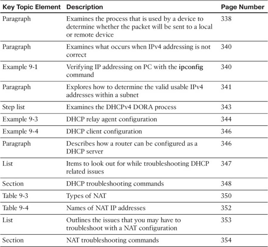
Table 9-6 Key Topics for Chapter 9
Define Key Terms
Define the following key terms from this chapter and check your answers in the glossary:
DHCP
DORA
DHCPDISCOVER
DHCPOFFER
DHCPREQUEST
DHCPACK
DHCP relay agent
APIPA
NAT
PAT/NAT overloading
static NAT
dynamic NAT
inside local
inside global
outside local
outside global
Command Reference to Check Your Memory
This section includes the most important verification and show commands covered in this chapter. It might not be necessary to memorize the complete syntax of every command, but you should be able to remember the basic keywords that are needed.
To test your memory of the commands, cover the right side of Table 9-7 with a piece of paper, read the description on the left side, and then see how much of the command you can remember.
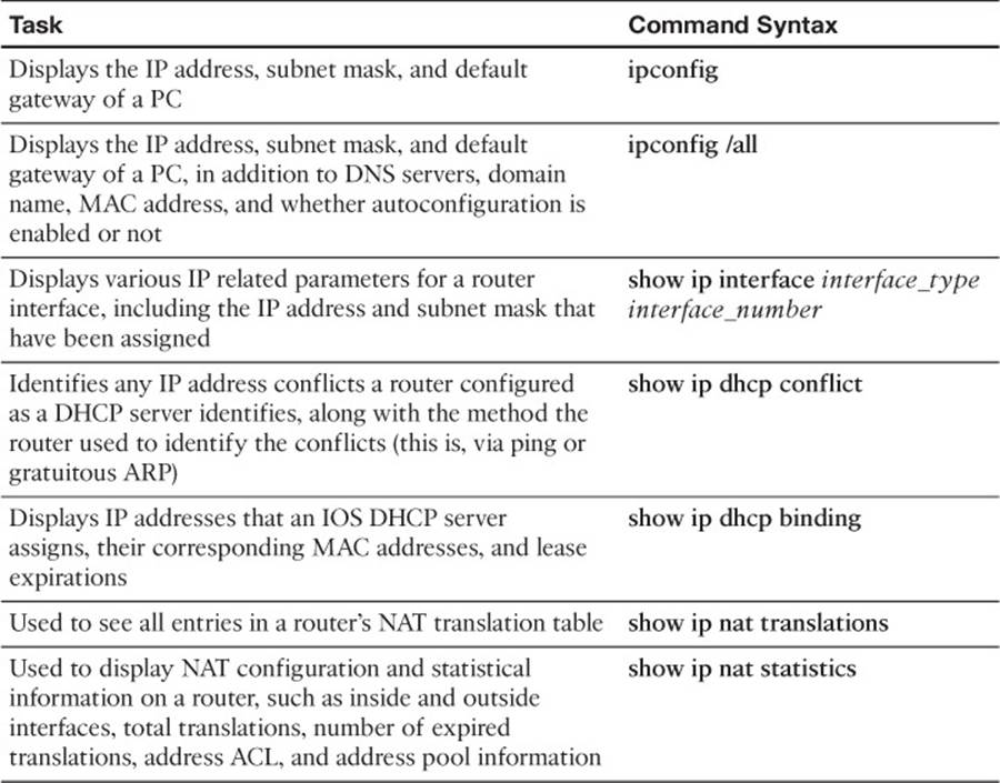
Table 9-7 Verification and show Commands
The 300-135 TSHOOT exam focuses on practical, hands-on skills that are used by a networking professional. Therefore, you should be able to identify the commands needed to verify and troubleshoot the topics covered in this chapter.
All materials on the site are licensed Creative Commons Attribution-Sharealike 3.0 Unported CC BY-SA 3.0 & GNU Free Documentation License (GFDL)
If you are the copyright holder of any material contained on our site and intend to remove it, please contact our site administrator for approval.
© 2016-2026 All site design rights belong to S.Y.A.