CCNP Routing and Switching TSHOOT 300-135 Official Cert Guide (2015)
Part III. Troubleshooting Router Features
Chapter 10. Troubleshooting IPv6 Addressing and Addressing Technologies
This chapter covers the following topics:
![]() Troubleshooting IPv6 Addressing: This section explains how IPv6 devices determine whether traffic is destined locally or remotely. In addition, the section covers how MAC addresses are learned with Neighbor Solicitation and Neighbor Advertisement messages when using IPv6.
Troubleshooting IPv6 Addressing: This section explains how IPv6 devices determine whether traffic is destined locally or remotely. In addition, the section covers how MAC addresses are learned with Neighbor Solicitation and Neighbor Advertisement messages when using IPv6.
![]() Troubleshooting IPv6 Address Assignment: This section identifies the different methods that you can use to assign IPv6 addresses to clients. These methods include SLAAC, stateless DHCPv6, and stateful DHCPv6. You will also learn how to verify and troubleshoot IPv6 address assignment methods.
Troubleshooting IPv6 Address Assignment: This section identifies the different methods that you can use to assign IPv6 addresses to clients. These methods include SLAAC, stateless DHCPv6, and stateful DHCPv6. You will also learn how to verify and troubleshoot IPv6 address assignment methods.
![]() IPv6 Addressing Trouble Tickets: This section provides trouble tickets that demonstrate how a structured troubleshooting process can be used to solve a reported problem.
IPv6 Addressing Trouble Tickets: This section provides trouble tickets that demonstrate how a structured troubleshooting process can be used to solve a reported problem.
Most organizations are still using IPv4; however, sooner or later they will have to switch to IPv6. When comparing IPv6 to IPv4, there is a whole lot more to IPv6 than it just being a larger address space. For example, because broadcasts have been removed from IPv6, multicast addresses are used in its place for addressing functions. Therefore, you need to be aware of these multicast addresses to successfully troubleshoot IPv6 addressing issues.
This chapter covers how an IPv6-enabled device determines whether the destination is local or remote. You will also learn how MAC addresses are determined for known IPv6 addresses, and you will explore the various options for address assignment and what to look for while troubleshooting related issues.
“Do I Know This Already?” Quiz
The “Do I Know This Already?” quiz allows you to assess whether you should read this entire chapter thoroughly or jump to the “Exam Preparation Tasks” section. If you are in doubt about your answers to these questions or your own assessment of your knowledge of the topics, read the entire chapter. Table 10-1 lists the major headings in this chapter and their corresponding “Do I Know This Already?” quiz questions. You can find the answers in Appendix A, “Answers to the ‘Do I Know This Already?’ Quizzes.”
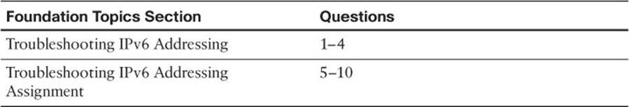
Table 10-1 “Do I Know This Already?” Section-to-Question Mapping
Caution
The goal of self-assessment is to gauge your mastery of the topics in this chapter. If you do not know the answer to a question or are only partially sure of the answer, you should mark that question as wrong for purposes of the self-assessment. Giving yourself credit for an answer that you correctly guess skews your self-assessment results and might provide you with a false sense of security.
1. What protocol is used with IPv6 to determine the MAC address of a device in the same local-area network?
a. Address Resolution Protocol
b. Inverse Address Resolution Protocol
c. Neighbor Discovery Protocol
d. Neighbor Solicitation
2. What type of message is used to determine the MAC address of a known IPv6 address?
a. Router Solicitation
b. Router Advertisement
c. Neighbor Solicitation
d. Neighbor Advertisement
3. Which of the following are true when using EUI-64? (Choose two answers.)
a. The interface MAC address is used unmodified.
b. The interface MAC address is used with FFFE added to the middle.
c. The seventh bit from the left in the MAC address is flipped.
d. The seventh bit from the right in the MAC address is flipped.
4. What command is used on a Cisco IOS router to enable SLAAC on an interface?
a. ipv6 address autoconfig
b. ipv6 address dhcp
c. ipv6 address prefix eui-64
d. ipv6 nd ra suppress
5. What are requirements for stateless autoconfiguration to function? (Choose three answers.)
a. The prefix must be a /64.
b. The router must be sending and not suppressing RA messages.
c. The router must be enabled for IPv6 unicast routing.
d. The router must be sending RS messages.
6. Which command is used on a Cisco IOS router to verify the IPv6 addresses that have been deployed to clients?
a. show ipv6 dhcp mappings
b. show ipv6 dhcp interface
c. show ipv6 dhcp binding
d. show ipv6 dhcp pool
7. Which command is used to enable a router to inform clients that they need to get additional configuration information from a DHCPv6 server?
a. ipv6 nd ra suppress
b. ipv6 dhcp relay destination
c. ipv6 address autoconfig
d. ipv6 nd other-config-flag
8. Which DHCPv6 message type is sent from the client as it is searching for a DHCPv6 server?
a. ADVERTISE
b. REPLY
c. SOLICIT
d. REQUEST
9. What is needed when a DHCPv6 server resides in a different network than the clients it is providing IPv6 addresses to?
a. Address Resolution Protocol
b. Neighbor Discovery Protocol
c. Relay agent
d. Network Address Translation
10. What command enables you to configure a router interface as a DHCPv6 relay agent?
a. ipv6 forwarder
b. ipv6 helper-address
c. ipv6 dhcp relay destination
d. ipv6 dhcp client
Foundation Topics
Troubleshooting IPv6 Addressing
Just like your personal street address uniquely defines where you live, an IPv6 address uniquely defines where a device resides. Your street address is made of two parts, the street name and the number of your residence; and the combination of these will be unique. The same is true with IPv6 addresses. They are made up of two parts. The first 64 bits usually represent the subnet prefix (what network you belong to), and the last 64 bits usually represent the interface ID/host ID (who you are in the network).
This section covers IPv6 addressing and assignment so that you are armed with the knowledge needed for troubleshooting IPv6 addressing issues.
IPv6 Addressing Review
As with IPv4, it is important that devices are configured with the appropriate IPv6 address based on where they reside so that packets can be successfully routed to and from them. Refer to Figure 10-1, which depicts an IPv6 network. 2001:db8:A:A::/64 represents the first 64 bits of the IPv6 address, which is the subnet prefix. This is the IPv6 network the nodes reside in. Router R1 has an interface IPv6 address of 2001:db8:a:a::1 where the last 64 bits, which are ::1 in this case, represent the interface/host ID or who it is in the IPv6 network. PC1 is ::10 and PC2 is ::20. All the devices in 2001:db8:a:a::/64 are configured with a default gateway address of R1’s Gig0/0 interface, which is 2001:db8:a:a::1.
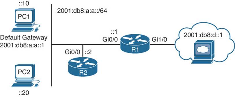
Figure 10-1 IPv6 Addressing Example
Neighbor Solicitation and Neighbor Advertisement
Just like IPv4, when a host wants to communicate with another host, it compares its subnet bits to the exact same bits in the destination IP address. If they match, both devices are in the same subnet; if they do not match, both devices are in different subnets. If both devices are in the same subnet, they can communicate directly with each other, and if they are in different subnets, they will need to communicate through the default gateway.
For example, referring to Figure 10-1 again, when PC1 needs to communicate with the server at 2001:db8:d::1, it realizes that the web server is in a different network. Therefore, PC1 has to send the frame to the default gateway using the default gateway’s MAC address. In IPv4, Address Resolution Protocol (ARP) was used to determine the MAC associated with an IPv4 address. ARP does not exist in IPv6, and neither do broadcasts. Instead, Neighbor Discovery Protocol (NDP) is used, which is based on multicasts.

Refer to Figure 10-2. In this case, PC1 sends a Neighbor Solicitation (NS) message sourced from its own IPv6 address 2001:db8:a:a::10 and MAC address 0800:275d:06d6. However, the destination IPv6 address and MAC address are solicited node multicast addresses because broadcasts do not exist. The IPv6 address solicited node multicast looks like this FF02:0:0:0:0:1:FFXX:XXXX. The X’s are replaced with the last 24 bits (6 hex values) of the destination’s IPv6 address. In this case, the IPv6 address of R1 (the destination) is 2001:db8:a:a::1. Therefore, the last 24 bits in hexadecimal would be 00:0001. So, the IPv6 destination solicited node multicast address would be FF02::1:FF00:1. The destination MAC solicited node multicast address looks like this 33:33:FF:XX:XX:XX. The last 24 bits (6 hex values) are the last 6 hex values of the IPv6 address (not MAC address). Therefore, the destination MAC address is 33:33:FF:00:00:01.
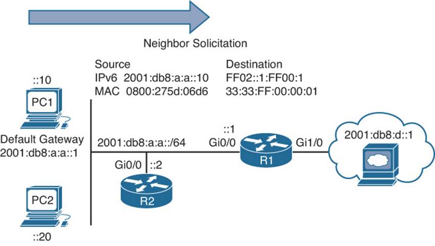
Figure 10-2 Neighbor Solicitation Example
Why does NDP go to this length just to send an NS message? Remember, there are no broadcasts with IPv6 at Layer 2 and Layer 3. Therefore, unicast communication or multicast communication is needed. Because we do not know the destination MAC, unicast is out of the question until we know it. So, multicast is used. However, you do not want to multicast to everyone, you only want to multicast to those devices that need to receive the multicast packet; therefore, those devices listening to the multicast group address. So, what is the group in this case? It is R1, the default gateway!
By default, all devices will create their own solicited node multicast group by appending the last 6 hex values of their IPv6 address to the IPv6 solicited node multicast address FF02:0:0:0:0:1:FF00::/104. As a result, when PC1 in our example sends the NS message, the destination is the solicited node multicast address that R1 is listening to. To verify the multicast groups that a router interface is listening to, you can use the show ipv6 interface interface_type interface_number command, as shown in Example 10-1. Notice that R1 is listening for packets destined to the multicast group FF02::1:FF00:1, as we had discussed with Figure 10-2. In addition, you can view the global unicast addresses assigned to the interface as well as the link-local address.

Example 10-1 Verifying IPv6 Multicast Groups a Router Interface Is Listening To
R1#show ipv6 interface gigabitEthernet 0/0
GigabitEthernet0/0 is up, line protocol is up
IPv6 is enabled, link-local address is FE80::C80A:4FF:FE84:8
No Virtual link-local address(es):
Global unicast address(es):
2001:DB8:A:A::1, subnet is 2001:DB8:A:A::/64
Joined group address(es):
FF02::1
FF02::1:FF00:1
FF02::1:FF84:8
MTU is 1500 bytes
ICMP error messages limited to one every 100 milliseconds
ICMP redirects are enabled
ICMP unreachables are sent
ND DAD is enabled, number of DAD attempts: 1
ND reachable time is 30000 milliseconds (using 30000)
ND NS retransmit interval is 1000 milliseconds
After R1 receives the NS message, it responds with a Neighbor Advertisement (NA), which will be a unicast packet. Refer to Figure 10-3, which shows R1 sending the NA to PC1 with a source IPv6 address 2001:db8:a:a::1 and MAC address ca0a.0484.0008.
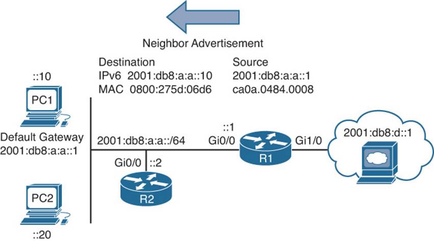
Figure 10-3 Neighbor Advertisement Example
Now PC1 can communicate with the server at 2001:db8:d::1 because it can send the frame to R1 and then R1 can route it.
You can verify the IPv6 address of a PC using the ipconfig command, as shown in Example 10-2. In this example, PC1 has a link-local address of fe80::a00:27ff:fe5d:6d6 and a global unicast address of 2001:db8:a:a::10, which was statically configured. Notice the %11 at the end of the link-local address in this case. This is the interface identification number. This is needed so that the system knows which interface to send the packets out of. The reason is because you can have multiple interfaces on the same device with the same link-local address assigned to it.
Example 10-2 Using ipconfig to Verify IPv6 Addressing
C:\PC1>ipconfig
Windows IP Configuration
Ethernet adapter Local Area Connection:
Connection-specific DNS Suffix . :
IPv6 Address. . . . . . . . . . . : 2001:db8:a:a::10
Link-local IPv6 Address . . . . . : fe80::a00:27ff:fe5d:6d6%11
IPv4 Address. . . . . . . . . . . : 10.1.1.10
Subnet Mask . . . . . . . . . . . : 255.255.255.192
Default Gateway . . . . . . . . . : 2001:db8:a:a::1
10.1.1.1
EUI-64
Recall that the IPv6 address consists of two parts: the subnet ID and the interface/host ID. The host ID is usually 64 bits long, and as a result is not something you want to be configuring manually in your organization. Although you can statically define the interface ID, the best approach is to allow your end devices to automatically assign their own interface ID for global unicast and link-local addresses based on the IEEE EUI-64 standard.
EUI-64 takes the clients MAC address, which is 48 bits, splits it in half, and adds the hex values FFFE in the middle. In addition, it takes the seventh bit from the left and flips it. So, if it is a 1, it becomes a 0, and if it is a 0, it becomes a 1. Look back at Example 10-2. Notice the link-local address is fe80::a00:27ff:fe5d:6d6. The subnet ID is FE80::, and the interface ID is a00:27ff:fe5d:6d6. Let’s fill in the missing leading 0s so that the address is 0a00:27ff:fe5d:06d6. This is an EUI-64 interface ID because it has FFFE in it. Let’s see how it is derived.
Example 10-3 displays the output of ipconfig /all on PC1. Notice that the MAC address is 08-00-27-5D-06-D6. Split it in half and add FFFE in the middle so that you get 08-00-27-FF-FE-5D-06-D6. Now group the hex values into groups of four and replace the dashes (-) with colons, like this: 0800:27FF:FE5D:06D6. This looks very close to what is listed in the link-local address, but it is not exact. The interface ID in the link-local address starts with 0a and ours starts with 08. This is because the seventh bit is flipped, as discussed earlier. Let’s flip it. 08 hex in binary is 00001000. The seventh bit from the left is a 0, so make it a 1. Now you have 00001010. Convert to hex and you get 0a. So, our interface ID is 0A00:27FF:FE5D:06D6.
Example 10-3 Using ipconfig /all to Verify IPv6 Addressing
C:\PC1>ipconfig /all
Windows IP Configuration
Host Name . . . . . . . . . . . . : PC1_Win7
Primary Dns Suffix . . . . . . . :
Node Type . . . . . . . . . . . . : Broadcast
IP Routing Enabled. . . . . . . . : No
WINS Proxy Enabled. . . . . . . . : No
Ethernet adapter Local Area Connection:
Connection-specific DNS Suffix . :
Description . . . . . . . . . . . : Intel(R) PRO/1000 MT Desktop Adapter
Physical Address. . . . . . . . . : 08-00-27-5D-06-D6
DHCP Enabled. . . . . . . . . . . : No
Autoconfiguration Enabled . . . . : Yes
IPv6 Address. . . . . . . . . . . : 2001:db8:a:a::10(Preferred)
Link-local IPv6 Address . . . . . : fe80::a00:27ff:fe5d:6d6%11(Preferred)
IPv4 Address. . . . . . . . . . . : 10.1.1.10(Preferred)
Subnet Mask . . . . . . . . . . . : 255.255.255.192
Default Gateway . . . . . . . . . : 2001:db8:a:a::1
10.1.1.1
DNS Servers . . . . . . . . . . . : fec0:0:0:ffff::1%1
fec0:0:0:ffff::2%1
fec0:0:0:ffff::3%1
NetBIOS over Tcpip. . . . . . . . : Enabled
By default, routers will use EUI-64 when generating the interface portion of the link-local address of an interface. Modern Windows PCs will randomly generate the interface portion by default for both the link-local address and the global unicast address when autoconfiguring their IPv6 addresses. However, this can be changed so that EUI-64 is used instead. When statically configuring an IPv6 address on a PC, the interface portion is manually assigned. However, on a router, if you want to use EUI-64 for a statically configured global unicast address, you can use the eui-64keyword at the end of the ipv6 address command, as shown in Example 10-4.
Example 10-4 Using EUI-64 on a Router Interface
R2#config t
Enter configuration commands, one per line. End with CNTL/Z.
R2(config)#interface gigabitEthernet 0/0
R2(config-if)#ipv6 address 2001:db8:a:a::/64 eui-64
You can verify the global unicast address and the EUI-64 interface ID assigned to it using the show ipv6 interface command, as shown in Example 10-5. In this case, R2’s Gig0/0 interface has a global unicast address that obtained the interface ID from the EUI-64 standard.
Example 10-5 Verifying EUI-64 on a Router Interface
R2#show ipv6 interface gigabitEthernet 0/0
GigabitEthernet0/0 is up, line protocol is up
IPv6 is enabled, link-local address is FE80::C80E:15FF:FEF4:8
No Virtual link-local address(es):
Global unicast address(es):
2001:DB8:A:A:C80E:15FF:FEF4:8, subnet is 2001:DB8:A:A::/64 [EUI]
Joined group address(es):
FF02::1
FF02::1:FFF4:8
MTU is 1500 bytes
...output omitted...
Troubleshooting IPv6 Address Assignment
Assigning any IP address (IPv4 or IPv6) manually is not a scalable option. With IPv4, you had Dynamic Host Configuration Protocol (DHCP) as your dynamic option. With IPv6, you have three dynamic options to choose from: stateless address autoconfiguration (or SLAAC for short), stateful DHCPv6, or stateless DHCPv6. Let’s look at the issues that might arise for each and how we can troubleshoot these issues.
Stateless Address Autoconfiguration/SLAAC
Stateless address autoconfiguration (SLAAC) is designed so that devices are able to configure their own IPv6 address, prefix, and default gateway without a DHCPv6 server. Windows PCs are automatically enabled for SLAAC and will generate their own IPv6 addresses, as shown inExample 10-6, which displays the output of ipconfig /all on PC1.
Example 10-6 Using ipconfig /all to Verify IPv6 SLAAC Is Enabled
C:\PC1>ipconfig /all
Windows IP Configuration
Host Name . . . . . . . . . . . . : PC1_Win7
Primary Dns Suffix . . . . . . . :
Node Type . . . . . . . . . . . . : Broadcast
IP Routing Enabled. . . . . . . . : No
WINS Proxy Enabled. . . . . . . . : No
Ethernet adapter Local Area Connection:
Connection-specific DNS Suffix . : SWITCH.local
Description . . . . . . . . . . . : Intel(R) PRO/1000 MT Desktop Adapter
Physical Address. . . . . . . . . : 08-00-27-5D-06-D6
DHCP Enabled. . . . . . . . . . . : Yes
Autoconfiguration Enabled . . . . : Yes
IPv6 Address. . . . . . . . . . . : 2001:db8::a00:27ff:fe5d:6d6(Preferred)
Link-local IPv6 Address . . . . . : fe80::a00:27ff:fe5d:6d6%11(Preferred)
IPv4 Address. . . . . . . . . . . : 10.1.1.10(Preferred)
Subnet Mask . . . . . . . . . . . : 255.255.255.192
...output omitted...
On Cisco routers, if you want to take advantage of SLAAC, you need to enable it manually on an interface with the ipv6 address autoconfig command, as shown in Example 10-7.
Example 10-7 Enabling SLAAC on a Router Interface
R2#config t
Enter configuration commands, one per line. End with CNTL/Z.
R2(config)#interface gigabitEthernet 0/0
R2(config-if)#ipv6 address autoconfig
When a Windows PC and router interface are enabled for SLAAC, they will send a Router Solicitation (RS) message to determine whether there are any routers connected to the local link. In turn, they wait for a router to send a Router Advertisement (RA) that identifies the prefix being used by the router (default gateway) connected to the same network they are on. They will then use that prefix information to generate their own IPv6 address in the same network as the router interface that generated the RA. The router will use EUI-64 for the interface portion, and the PC will randomly generate the interface portion unless it is configured to use EUI-64. In addition, the PC will use the IPv6 link-local address of the device that sent the RA as the default gateway address.
Refer to Figure 10-4, which displays the RA process. R1 sends an RA out its Gig0/0 interface. The source IPv6 address is the Gig0/0 link-local address, and the source MAC address is the MAC address of interface Gig0/0. The destination IPv6 address is the all-nodes link-local multicast IPv6 address of FF02::1. The destination MAC address is the all-nodes destination MAC address of 33:33:00:00:00:01 that is associated with the all-nodes link-local multicast IPv6 address FF02::1. By default, all IPv6-enabled interfaces listen for packets and frames destined for these two addresses.
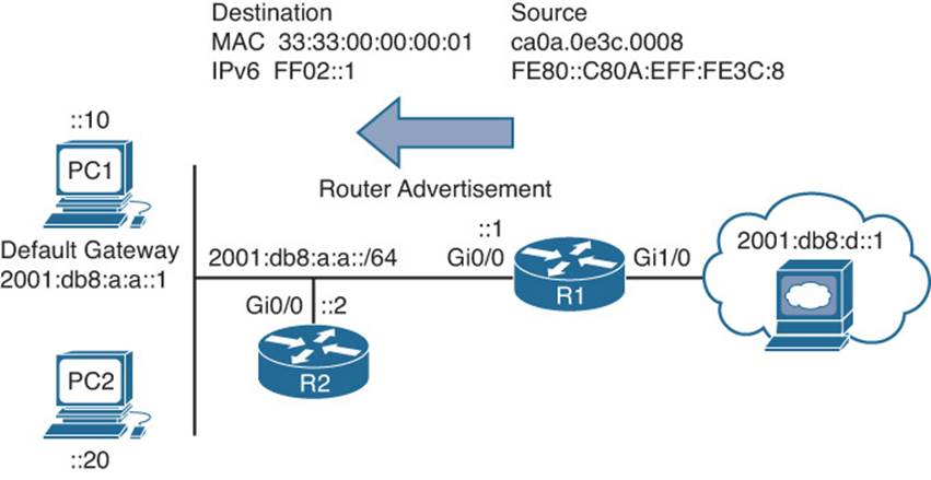
Figure 10-4 Router Advertisement Example
Once PC1 in Figure 10-4 receives the RA, it takes the prefix included in the RA, which is 2001:db8:a:a::/64, and in this case uses EUI-64 to create its IPv6 address. It also takes the link-local address from the source of the RA and uses it as the default gateway address, as shown in Example 10-8, which displays the output of ipconfig on PC1.
Example 10-8 Verifying IPv6 Addresses Generated by SLAAC on a PC
C:\PC1>ipconfig
Windows IP Configuration
Ethernet adapter Local Area Connection:
Connection-specific DNS Suffix . :
IPv6 Address. . . . . . . . . . . : 2001:db8:a:a:a00:27ff:fe5d:6d6
Link-local IPv6 Address . . . . . : fe80::a00:27ff:fe5d:6d6%11
IPv4 Address. . . . . . . . . . . : 10.1.1.10
Subnet Mask . . . . . . . . . . . : 255.255.255.192
Default Gateway . . . . . . . . . : fe80::c80a:eff:fe3c:8%11
10.1.1.1
To verify an IPv6 address generated by SLAAC on a router interface, use the show ipv6 interface command. As shown in Example 10-9, the global unicast address was generated using SLAAC. Also notice at the bottom of the example that the default router is listed as the link-local address of R1. However, note that this will occur only if IPv6 unicast routing has not been enabled on the router and as a result the router is acting as an end device.
Example 10-9 Verifying IPv6 Addresses Generated by SLAAC on a Router Interface
R2#show ipv6 interface gig 0/0
GigabitEthernet0/0 is up, line protocol is up
IPv6 is enabled, link-local address is FE80::C80B:EFF:FE3C:8
No Virtual link-local address(es):
Stateless address autoconfig enabled
Global unicast address(es):
2001:DB8:A:A:C80B:EFF:FE3C:8, subnet is 2001:DB8:A:A::/64 [EUI/CAL/PRE]
valid lifetime 2591816 preferred lifetime 604616
Joined group address(es):
FF02::1
FF02::1:FF3C:8
MTU is 1500 bytes
ICMP error messages limited to one every 100 milliseconds
ICMP redirects are enabled
ICMP unreachables are sent
ND DAD is enabled, number of DAD attempts: 1
ND reachable time is 30000 milliseconds (using 30000)
ND NS retransmit interval is 1000 milliseconds
Default router is FE80::C80A:EFF:FE3C:8 on GigabitEthernet0/0
It is important to realize that RAs are generated by default on router interfaces only if the router interface is enabled for IPv6, IPv6 unicast routing is enabled, and RAs are not being suppressed on the interface. Therefore, if SLAAC is not working, check the following:
![]() Make sure that IPv6 unicast routing is enabled on the router that should be generating RAs by using the show run | include ipv6 unicast-routing command, as shown in Example 10-10.
Make sure that IPv6 unicast routing is enabled on the router that should be generating RAs by using the show run | include ipv6 unicast-routing command, as shown in Example 10-10.
![]() Make sure that the appropriate interface is enabled for IPv6 with the show ipv6 interface command, as shown in Example 10-11.
Make sure that the appropriate interface is enabled for IPv6 with the show ipv6 interface command, as shown in Example 10-11.
![]() Make sure that the router interface advertising RAs has a /64 prefix by using the show ipv6 interface command, as shown in Example 10-11. (SLAAC works only if the router is using a /64 prefix.)
Make sure that the router interface advertising RAs has a /64 prefix by using the show ipv6 interface command, as shown in Example 10-11. (SLAAC works only if the router is using a /64 prefix.)
![]() Make sure that RAs are not being suppressed on the interface by using the show ipv6 interface command, as shown in Example 10-12. In this example they are.
Make sure that RAs are not being suppressed on the interface by using the show ipv6 interface command, as shown in Example 10-12. In this example they are.
Example 10-10 Verifying IPv6 Unicast Routing Is Enabled on a Router
R1#show run | include ipv6 unicast-routing
ipv6 unicast-routing
Example 10-11 Verifying an Interface Is Enabled for IPv6
R1#show ipv6 interface gigabitEthernet 0/0
GigabitEthernet0/0 is up, line protocol is up
IPv6 is enabled, link-local address is FE80::C80A:EFF:FE3C:8
No Virtual link-local address(es):
Global unicast address(es):
2001:DB8:A:A::1, subnet is 2001:DB8:A:A::/64
Joined group address(es):
FF02::1
FF02::2
FF02::1:FF00:1
FF02::1:FF3C:8
...output omitted...
Example 10-12 Verifying that RAs Are Not Suppressed
R1#show ipv6 interface gigabitEthernet 0/0
GigabitEthernet0/0 is up, line protocol is up
IPv6 is enabled, link-local address is FE80::C80A:EFF:FE3C:8
No Virtual link-local address(es):
Global unicast address(es):
2001:DB8:A:A::1, subnet is 2001:DB8:A:A::/64
Joined group address(es):
FF02::1
FF02::2
FF02::1:FF00:1
FF02::1:FF3C:8
MTU is 1500 bytes
ICMP error messages limited to one every 100 milliseconds
ICMP redirects are enabled
ICMP unreachables are sent
ND DAD is enabled, number of DAD attempts: 1
ND reachable time is 30000 milliseconds (using 30000)
ND RAs are suppressed (all)
Hosts use stateless autoconfig for addresses.
In addition, if you have more than one router on the subnet generating RAs, which is normal when you have redundant default gateways, the clients will learn about multiple default gateways from the RAs, as shown in Example 10-13. The top default gateway is R2’s link-local address, and the bottom default gateway is R1’s link-local address. Now, this might seem like a benefit; however, it is a benefit only if both default gateways can reach the same networks. Refer to Figure 10-5. If PC1 uses R2 as the default gateway, the packets to the web server will be dropped because R2 does not have a way to route packets to the web server, as shown in the Example 10-14 ping, unless it redirects them back out the interface they arrived on, which is not a normal behavior. Therefore, if users are complaining that they cannot access resources, and they are connected to a network with multiple routers generating RAs, check the default gateways learned by SLAAC and make sure that those default gateways can route to the intended resources.
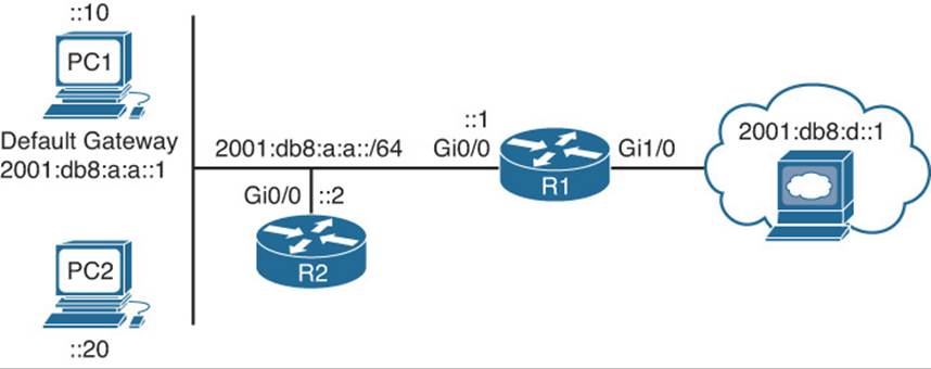
Figure 10-5 Redundant Default Gateways
Example 10-13 Verifying Default Gateways Configured on a PC
C:\PC1>#ipconfig
Windows IP Configuration
Ethernet adapter Local Area Connection:
Connection-specific DNS Suffix . :
IPv6 Address. . . . . . . . . . . : 2001:db8:a:a:a00:27ff:fe5d:6d6
Link-local IPv6 Address . . . . . : fe80::a00:27ff:fe5d:6d6%11
IPv4 Address. . . . . . . . . . . : 10.1.1.10
Subnet Mask . . . . . . . . . . . : 255.255.255.192
Default Gateway . . . . . . . . . : fe80::c80b:eff:fe3c:8%11
fe80::c80a:eff:fe3c:8%11
10.1.1.1
Example 10-14 Failed Ping from PC1 to 2001:db8:a:a::1
C:\PC1>ping 2001:db8:d::1
Pinging 2001:db8:d::1 with 32 bytes of data:
Destination net unreachable.
Destination net unreachable.
Destination net unreachable.
Destination net unreachable.
Ping statistics for 2001:db8:d::1:
Packets: Sent = 4, Received = 0, Lost = 4 (100% loss),
Stateful DHCPv6
Although a device is able to determine its IPv6 address, prefix, and default gateway using SLAAC, there is not much else the devices can obtain. In a modern-day network, the devices may also need Network Time Protocol (NTP) server information, domain name information, DNS server information, and TFTP server information to name a few. To hand out the IPv6 addressing information along with all optional information, you need to use a DHCPv6 server. Both Cisco routers and multilayer switches can act as DHCP servers. Example 10-15 provides a sample DHCPv6 configuration on R1 and the ipv6 dhcp server interface command necessary to enable the interface to use the DHCP pool for handing out IPv6 addressing information. If you are troubleshooting an issue where clients are not receiving IPv6 addressing information or wrong IPv6 addressing information from a router or multilayer switch acting as a DHCPv6 server, check the interface and make sure that it has been associated with the correct pool.
Example 10-15 Sample DHCPv6 Configuration on R1
R1#show run | section dhcp
ipv6 dhcp pool DHCPV6POOL
address prefix 2001:DB8:A:A::/64
dns-server 2001:DB8:B:B::1
domain-name TSHOOT.com
R1#show run interface gigabitEthernet 0/0
Building configuration...
Current configuration : 173 bytes
!
interface GigabitEthernet0/0
no ip address
ipv6 address 2001:DB8:A:A::1/64
ipv6 dhcp server DHCPV6POOL
end
In Example 10-16, you can see samples of the show ipv6 dhcp binding command, which displays the IPv6 addresses that are being used by clients, the show ipv6 dhcp interface command, which displays the IPv6 addresses that are being used by clients, and the show ipv6 dhcp poolcommand, which displays the configured pools.
Example 10-16 Verifying DHCPv6 Information on R1
R1#show ipv6 dhcp binding
Client: FE80::A00:27FF:FE5D:6D6
DUID: 000100011B101C740800275D06D6
Username : unassigned
VRF : default
IA NA: IA ID 0x0E080027, T1 43200, T2 69120
Address: 2001:DB8:A:A:D519:19AB:E903:F802
preferred lifetime 86400, valid lifetime 172800
expires at May 25 2014 08:37 PM (172584 seconds)
R1#show ipv6 dhcp interface
GigabitEthernet0/0 is in server mode
Using pool: DHCPV6POOL
Preference value: 0
Hint from client: ignored
Rapid-Commit: disabled
R1#show ipv6 dhcp pool
DHCPv6 pool: DHCPV6POOL
Address allocation prefix: 2001:DB8:A:A::/64 valid 172800 preferred 86400 (1 in
use, 0 conflicts)
DNS server: 2001:DB8:B:B::1
Domain name: TSHOOT.com
Active clients: 0
Stateless DHCPv6
Stateless DHCPv6 is a combination of SLAAC and DHCPv6. In this case, a router’s RA is used by the clients to automatically determine their IPv6 address, prefix, and default gateway. Included in the RA is a flag that tells the client to get other nonaddressing information from a DHCPv6 server, such as the address of a DNS server or a TFTP server. To accomplish this you need to ensure that the ipv6 nd other-config-flag interface configuration command is enabled. This ensures that the RA informs the client that it must contact a DHCPv6 server for other information. InExample 10-17, you can see this command configured under interface Gigabit Ethernet 0/0. Also, in Example 10-17, you can see the output of show ipv6 interface gigabitEthernet 0/0, which states that hosts will obtain IPv6 addressing from stateless autoconfig and other information from aDHCP server.
Example 10-17 Verifying Stateless DHCPv6
R1#show run int gig 0/0
Building configuration...
Current configuration : 171 bytes
!
interface GigabitEthernet0/0
no ip address
media-type gbic
speed 1000
duplex full
negotiation auto
ipv6 address 2001:DB8:A:A::1/64
ipv6 nd other-config-flag
end
R1#show ipv6 interface gigabitEthernet 0/0
GigabitEthernet0/0 is up, line protocol is up
IPv6 is enabled, link-local address is FE80::C80A:EFF:FE3C:8
No Virtual link-local address(es):
Global unicast address(es):
2001:DB8:A:A::1, subnet is 2001:DB8:A:A::/64
Joined group address(es):
FF02::1
FF02::2
FF02::1:FF00:1
FF02::1:FF3C:8
...output omitted...
ND advertised default router preference is Medium
Hosts use stateless autoconfig for addresses.
Hosts use DHCP to obtain other configuration.
Example 10-18 shows the ipconfig /all output on PC1 after it has used stateless autoconfig for IPv6 addressing and then contacted a DHCPv6 server for DNS and domain name information.
Example 10-18 Verifying IPv6 Configuration on PC1
C:\PC1>ipconfig /all
Windows IP Configuration
Host Name . . . . . . . . . . . . : PC1_Win7
Primary Dns Suffix . . . . . . . :
Node Type . . . . . . . . . . . . : Broadcast
IP Routing Enabled. . . . . . . . : No
WINS Proxy Enabled. . . . . . . . : No
DNS Suffix Search List. . . . . . : TSHOOT.com
Ethernet adapter Local Area Connection:
Connection-specific DNS Suffix . : TSHOOT.com
Description . . . . . . . . . . . : Intel(R) PRO/1000 MT Desktop Adapter
Physical Address. . . . . . . . . : 08-00-27-5D-06-D6
DHCP Enabled. . . . . . . . . . . : No
Autoconfiguration Enabled . . . . : Yes
IPv6 Address. . . . . . . . . . . : 2001:db8:a:a:a00:27ff:fe5d:6d6(Preferred)
Link-local IPv6 Address . . . . . : fe80::a00:27ff:fe5d:6d6%11(Preferred)
IPv4 Address. . . . . . . . . . . : 10.1.1.10(Preferred)
Subnet Mask . . . . . . . . . . . : 255.255.255.192
Default Gateway . . . . . . . . . : fe80::c80a:eff:fe3c:8%11
10.1.1.1
DHCPv6 IAID . . . . . . . . . . . : 235405351
DHCPv6 Client DUID. . . . . . . . : 00-01-00-01-1B-10-1C-74-08-00-27-5D-06-D6
DNS Servers . . . . . . . . . . . : 2001:db8:b:b::10
NetBIOS over Tcpip. . . . . . . . : Enabled
Connection-specific DNS Suffix Search List : TSHOOT.com
DHCPv6 Operation
DHCPv6 has a four-way negotiation process, like IPv4. However, DHCPv6 uses the following messages:
Step 1. SOLICIT: A client sends this message to locate DHCPv6 servers using the multicast address FF02::1:2, which is the all DHCPv6 servers multicast address.
Step 2. ADVERTISE: Servers respond to SOLICIT messages with a unicast ADVERTISE message offering addressing information to the client.
Step 3. REQUEST: The client sends this message to the server confirming the addresses provided and any other parameters.
Step 4. REPLY: The server finalizes the process with this message.
As a reference, Table 10-2 provides a comprehensive listing of DHCPv6 message types you might encounter while troubleshooting a DHCPv6 issue.
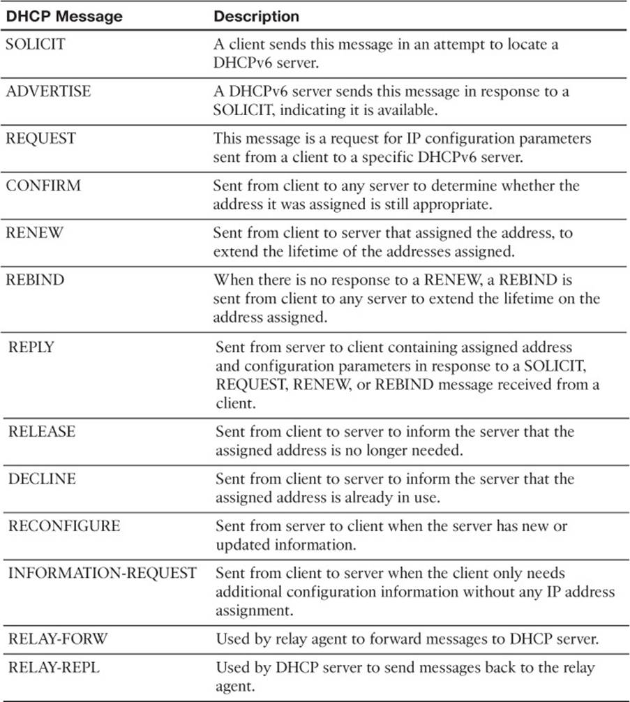
Table 10-2 DHCP Message Types
DHCPv6 Relay Agent
All the DHCPv6 examples so far have included the DHCP server within the same local network. However, in most networks, the DHCP server will be located in a different network, which creates an issue. If you review the multicast address of the SOLICIT message, you will notice it is a link-local scope multicast address. It starts with FF02. Therefore, the multicast will not leave the local network, and the client will not be able to reach the DHCPv6 server.
To relay the DHCPv6 messages to a DHCPv6 server in another network, the local router interface in the network the client belongs needs to be configured as a relay agent with the ipv6 dhcp relay destination interface configuration command. Example 10-19 shows interface Gigabit Ethernet 0/0 configured with the command ipv6 dhcp relay destination 2001:db8:a:b::7, which will be used to forward SOLICIT messages to a DHCPv6 server at the address listed.
Example 10-19 Configuring R1 as a DHCPv6 Relay Agent
R1#config t
Enter configuration commands, one per line. End with CNTL/Z.
R1(config)#interface gigabitethernet0/0
R1(config-if)#ipv6 dhcp relay destination 2001:db8:a:b::7
IPv6 Addressing Trouble Tickets
This section presents various trouble tickets relating to the topics discussed earlier in the chapter. The purpose of these trouble tickets is to give a process that you can follow when troubleshooting in the real world or in an exam environment. All trouble tickets in this section are based on the topology depicted in Figure 10-6.
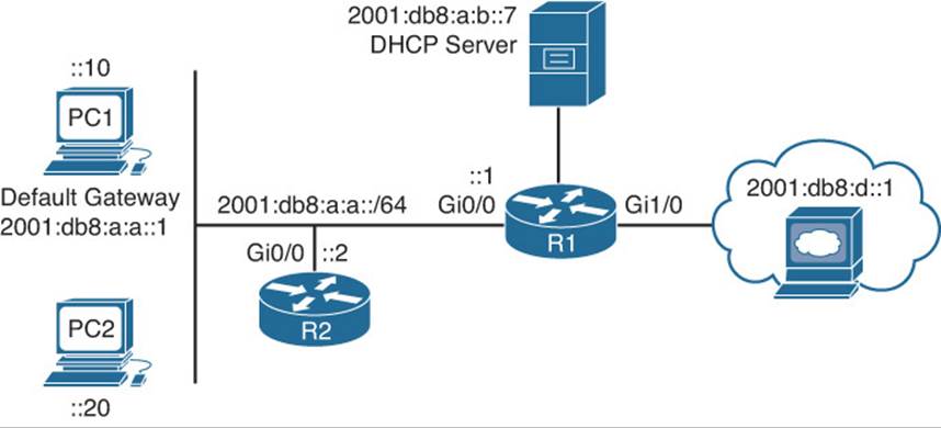
Figure 10-6 IPv6 Addressing Trouble Tickets Topology
Trouble Ticket 10-1
Problem: PC1 is not able to access resources on the web server at 2001:db8:d::1.
Your network uses stateless autoconfiguration for IPv6 addressing and DHCPv6 for additional options such as a domain name, TFTP server addresses, and DNS server addresses.
You begin troubleshooting by verifying the issue with a ping from PC1 to 2001:db8:d::1. As shown in Example 10-20, the ping fails.
Example 10-20 Failed Ping from PC1 to Web Server at 2001:db8:d::1
C:\PC1>ping 2001:db8:d::1
Pinging 2001:db8:d::1 with 32 bytes of data:
PING: transmit failed. General failure.
PING: transmit failed. General failure.
PING: transmit failed. General failure.
PING: transmit failed. General failure.
Ping statistics for 2001:db8:d::1:
Packets: Sent = 4, Received = 0, Lost = 4 (100% loss),
You ping the default gateway at 2001:db8:a:a::1, but the ping fails, as shown in Example 10-21.
Example 10-21 Failed Ping from PC1 to Default Gateway at 2001:db8:a:a::1
C:\PC1>ping 2001:db8:a:a::1
Pinging 2001:db8:a:a::1 with 32 bytes of data:
PING: transmit failed. General failure.
PING: transmit failed. General failure.
PING: transmit failed. General failure.
PING: transmit failed. General failure.
Ping statistics for 2001:db8:a:a::1:
Packets: Sent = 4, Received = 0, Lost = 4 (100% loss),
Next you verify the IPv6 addresses on PC1 using the ipconfig command. Example 10-22 indicates that PC1 is not generating its own global unicast address using stateless autoconfiguration or identifying a default gateway on the network.
Example 10-22 Verifying IPv6 Addressing on PC1
C:\PC1>ipconfig
Windows IP Configuration
Ethernet adapter Local Area Connection:
Connection-specific DNS Suffix . : TSHOOT.com
Link-local IPv6 Address . . . . . : fe80::a00:27ff:fe5d:6d6%11
IPv4 Address. . . . . . . . . . . : 10.1.1.10
Subnet Mask . . . . . . . . . . . : 255.255.255.192
Default Gateway . . . . . . . . . : 10.1.1.1
Your phone rings, and the user at PC2 is indicating that he cannot access any of the IPv6-enabled resources. You access PC2 and issue the ipconfig command, as shown in Example 10-23, and notice that it is not generating an IPv6 address either or identifying a default gateway.
Example 10-23 Verifying IPv6 Addressing on PC2
C:\PC2>ipconfig
Windows IP Configuration
Ethernet adapter Local Area Connection:
Connection-specific DNS Suffix . : TSHOOT.com
Link-local IPv6 Address . . . . . : fe80::a00:27ff:fe5d:ce47%9
IPv4 Address. . . . . . . . . . . : 10.1.1.20
Subnet Mask . . . . . . . . . . . : 255.255.255.192
Default Gateway . . . . . . . . . : 10.1.1.1
Recall that SLAAC relies on RAs. Therefore, R1’s Gig0/0 interface needs to be sending RAs on the link for PC1 and PC2 to generate their own IPv6 addresses using SLAAC. You issue the command show ipv6 interface gigabitethernet0/0 on R1, as shown in Example 10-24. The output indicates that hosts will use SLAAC for addresses, and DHCP will be used for other configuration values. However, it also indicates that RAs are suppressed. Therefore, PC1 and PC2 will not be receiving RAs that provide the prefix information necessary to perform autoconfiguration.
Example 10-24 Verifying Whether RAs Are Suppressed on R1
R1#show ipv6 interface gigabitEthernet 0/0
GigabitEthernet0/0 is up, line protocol is up
IPv6 is enabled, link-local address is FE80::C80A:EFF:FE3C:8
No Virtual link-local address(es):
Global unicast address(es):
2001:DB8:A:A::1, subnet is 2001:DB8:A:A::/64
Joined group address(es):
FF02::1
FF02::2
FF02::1:2
FF02::1:FF00:1
FF02::1:FF3C:8
MTU is 1500 bytes
ICMP error messages limited to one every 100 milliseconds
ICMP redirects are enabled
ICMP unreachables are sent
ND DAD is enabled, number of DAD attempts: 1
ND reachable time is 30000 milliseconds (using 30000)
ND RAs are suppressed (all)
Hosts use stateless autoconfig for addresses.
Hosts use DHCP to obtain other configuration.
You issue the command show run interface gigabitethernet0/0 to verify the configuration commands on the interface. As shown in Example 10-25, the interface is configured with the command ipv6 nd ra suppress all, which stops R1 from sending RAs.
Example 10-25 Verifying Interface Configuration on R1
R1#show run interface gigabitEthernet 0/0
Building configuration...
Current configuration : 241 bytes
!
interface GigabitEthernet0/0
no ip address
ipv6 address 2001:DB8:A:A::1/64
ipv6 nd other-config-flag
ipv6 nd ra suppress all
ipv6 dhcp relay destination 2001:DB8:A:B::7
end
After you remove this command with the no ipv6 nd ra suppress all command, PC1 successfully generates a global IPv6 address and identifies an IPv6 default gateway, as shown in Example 10-26.
Example 10-26 Verifying IPv6 Addressing on PC1
C:\PC1>ipconfig
Windows IP Configuration
Ethernet adapter Local Area Connection:
Connection-specific DNS Suffix . : TSHOOT.com
IPv6 Address. . . . . . . . . . . : 2001:db8:a:a:a00:27ff:fe5d:6d6
Link-local IPv6 Address . . . . . : fe80::a00:27ff:fe5d:6d6%11
IPv4 Address. . . . . . . . . . . : 10.1.1.10
Subnet Mask . . . . . . . . . . . : 255.255.255.192
Default Gateway . . . . . . . . . : fe80::c80a:eff:fe3c:8%11
10.1.1.1
You confirm that IPv6 resources are accessible by pinging 2001:db8:d::1 in Example 10-27, and it is successful. You then call the user at PC2 and confirm that he can access the resources as well. He indicates that he is.
Example 10-27 Successful Ping from PC1 to Web Server at 2001:db8:d::1
C:\PC1>ping 2001:db8:d::1
Pinging 2001:db8:d::1 with 32 bytes of data:
Reply from 2001:db8:d::1: time=37ms
Reply from 2001:db8:d::1: time=35ms
Reply from 2001:db8:d::1: time=38ms
Reply from 2001:db8:d::1: time=38ms
Ping statistics for 2001:db8:d::1:
Packets: Sent = 4, Received = 4, Lost = 0 (0% loss),
Approximate round trip times in milli-seconds:
Minimum = 35ms, Maximum = 38ms, Average = 36ms
Trouble Ticket 10-2
Problem: PC1 is not able to access resources on the web server at 2001:db8:d::1.
Your network uses stateless autoconfiguration for IPv6 addressing and DHCPv6 for additional options such as a domain name, TFTP server addresses, and DNS server addresses.
You begin troubleshooting by verifying the issue with a ping from PC1 to 2001:db8:d::1. As shown in Example 10-28, the ping fails.
Example 10-28 Failed Ping from PC1 to Web Server at 2001:db8:d::1
C:\PC1>ping 2001:db8:d::1
Pinging 2001:db8:d::1 with 32 bytes of data:
PING: transmit failed. General failure.
PING: transmit failed. General failure.
PING: transmit failed. General failure.
PING: transmit failed. General failure.
Ping statistics for 2001:db8:d::1:
Packets: Sent = 4, Received = 0, Lost = 4 (100% loss),
You ping the default gateway at 2001:db8:a:a::1, but the ping fails, as shown in Example 10-29.
Example 10-29 Failed Ping from PC1 to Default Gateway at 2001:db8:a:a::1
C:\PC1>ping 2001:db8:a:a::1
Pinging 2001:db8:a:a::1 with 32 bytes of data:
PING: transmit failed. General failure.
PING: transmit failed. General failure.
PING: transmit failed. General failure.
PING: transmit failed. General failure.
Ping statistics for 2001:db8:a:a::1:
Packets: Sent = 4, Received = 0, Lost = 4 (100% loss),
Next you verify the IPv6 addresses on PC1 using the ipconfig command. Example 10-30 indicates that PC1 is not generating its own global unicast address using stateless autoconfiguration; however, it is identifying a default gateway on the network at the link-local address fe80::c80a:eff:fe3c:8.
Example 10-30 Verifying IPv6 Addressing on PC1
C:\PC1>ipconfig
Windows IP Configuration
Ethernet adapter Local Area Connection:
Connection-specific DNS Suffix . : TSHOOT.com
Link-local IPv6 Address . . . . . : fe80::a00:27ff:fe5d:6d6%11
IPv4 Address. . . . . . . . . . . : 10.1.1.10
Subnet Mask . . . . . . . . . . . : 255.255.255.192
Default Gateway . . . . . . . . . : fe80::c80a:eff:fe3c:8%11
10.1.1.1
Your phone rings, and the user at PC2 is indicating that she cannot access any of the IPv6-enabled resources. You access PC2 and issue the ipconfig command, as shown in Example 10-31, and notice that it is experiencing the same issues as PC1.
Example 10-31 Verifying IPv6 Addressing on PC2
C:\PC2>ipconfig
Windows IP Configuration
Ethernet adapter Local Area Connection:
Connection-specific DNS Suffix . : TSHOOT.com
Link-local IPv6 Address . . . . . : fe80::a00:27ff:fe5d:ce47%9
IPv4 Address. . . . . . . . . . . : 10.1.1.10
Subnet Mask . . . . . . . . . . . : 255.255.255.192
Default Gateway . . . . . . . . . : fe80::c80a:eff:fe3c:8%11
10.1.1.1
Recall that SLAAC relies on RAs. Therefore, R1’s Gig0/0 interface needs to be sending RAs on the link for PC1 and PC2 to generate their own IPv6 address using SLAAC. You issue the command show ipv6 interface gigabitethernet0/0 on R1, as shown in Example 10-32. The output indicates that hosts will use SLAAC for addresses, and DHCP will be used for other configuration values. Also, there is no indication that RAs are being suppressed. This is also confirmed by the fact that PC1 and PC2 are identifying a default gateway. However, is it the right one? According to Examples 10-30 and 10-31, the default gateway is fe80::c80a:eff:fe3c:8. Based on Example 10-32, this is correct. Review Example 10-32 further; can you see the issue?
Example 10-32 Verifying Whether RAs Are Suppressed on R1
R1#show ipv6 interface gigabitEthernet 0/0
GigabitEthernet0/0 is up, line protocol is up
IPv6 is enabled, link-local address is FE80::C80A:EFF:FE3C:8
No Virtual link-local address(es):
Global unicast address(es):
2001:DB8:A:A::1, subnet is 2001:DB8:A::/60
Joined group address(es):
FF02::1
FF02::2
FF02::1:2
FF02::1:FF00:1
FF02::1:FF3C:8
MTU is 1500 bytes
ICMP error messages limited to one every 100 milliseconds
ICMP redirects are enabled
ICMP unreachables are sent
ND DAD is enabled, number of DAD attempts: 1
ND reachable time is 30000 milliseconds (using 30000)
ND advertised reachable time is 0 (unspecified)
ND advertised retransmit interval is 0 (unspecified)
ND router advertisements are sent every 200 seconds
ND router advertisements live for 1800 seconds
ND advertised default router preference is Medium
Hosts use stateless autoconfig for addresses.
Hosts use DHCP to obtain other configuration.
If you have not spotted it, look at the global prefix assigned to interface Gig0/0: 2001:db8:a::/60. SLAAC works only if the prefix is /64.
You issue the command show run interface gigabitethernet0/0 to verify the configuration commands on the interface. As shown in Example 10-33, the interface is configured with the command ipv6 address 2001:db8:a:a::1/60. RAs are still generated, but SLAAC will not work unless the prefix is a /64.
Example 10-33 Verifying Interface Configuration on R1
R1#show run interface gigabitEthernet 0/0
Building configuration...
Current configuration : 216 bytes
!
interface GigabitEthernet0/0
ipv6 address 2001:DB8:A:A::1/60
ipv6 nd other-config-flag
ipv6 dhcp relay destination 2001:DB8:A:B::7
end
After you remove this command with the no ipv6 address 2001:db8:a:a::1/60 command, and issue the command ipv6 address 2001:db8:a:a::1/64, PC1 successfully generates a global IPv6 unicast address, as shown in Example 10-34.
Example 10-34 Verifying IPv6 Addressing on PC1
C:\PC1>ipconfig
Windows IP Configuration
Ethernet adapter Local Area Connection:
Connection-specific DNS Suffix . : TSHOOT.com
IPv6 Address. . . . . . . . . . . : 2001:db8:a:a:a00:27ff:fe5d:6d6
Link-local IPv6 Address . . . . . : fe80::a00:27ff:fe5d:6d6%11
IPv4 Address. . . . . . . . . . . : 10.1.1.10
Subnet Mask . . . . . . . . . . . : 255.255.255.192
Default Gateway . . . . . . . . . : fe80::c80a:eff:fe3c:8%11
10.1.1.1
You confirm that IPv6 resources are accessible by pinging 2001:db8:d::1 in Example 10-35, and it is successful. In addition, you contact the user at PC2, and she indicates that everything is fine now.
Example 10-35 Successful Ping from PC1 to Web Server at 2001:db8:d::1
C:\PC1>ping 2001:db8:d::1
Pinging 2001:db8:d::1 with 32 bytes of data:
Reply from 2001:db8:d::1: time=37ms
Reply from 2001:db8:d::1: time=35ms
Reply from 2001:db8:d::1: time=38ms
Reply from 2001:db8:d::1: time=38ms
Ping statistics for 2001:db8:d::1:
Packets: Sent = 4, Received = 4, Lost = 0 (0% loss),
Approximate round trip times in milli-seconds:
Minimum = 35ms, Maximum = 38ms, Average = 36ms
Exam Preparation Tasks
As mentioned in the section “How to Use This Book” in the Introduction, you have a couple of choices for exam preparation: the exercises here; Chapter 22, “Final Preparation;” and the exam simulation questions on the CD-ROM.
Review All Key Topics
Review the most important topics in this chapter, noted with the Key Topic icon in the outer margin of the page. Table 10-3 lists a reference of these key topics and the page numbers on which each is found.
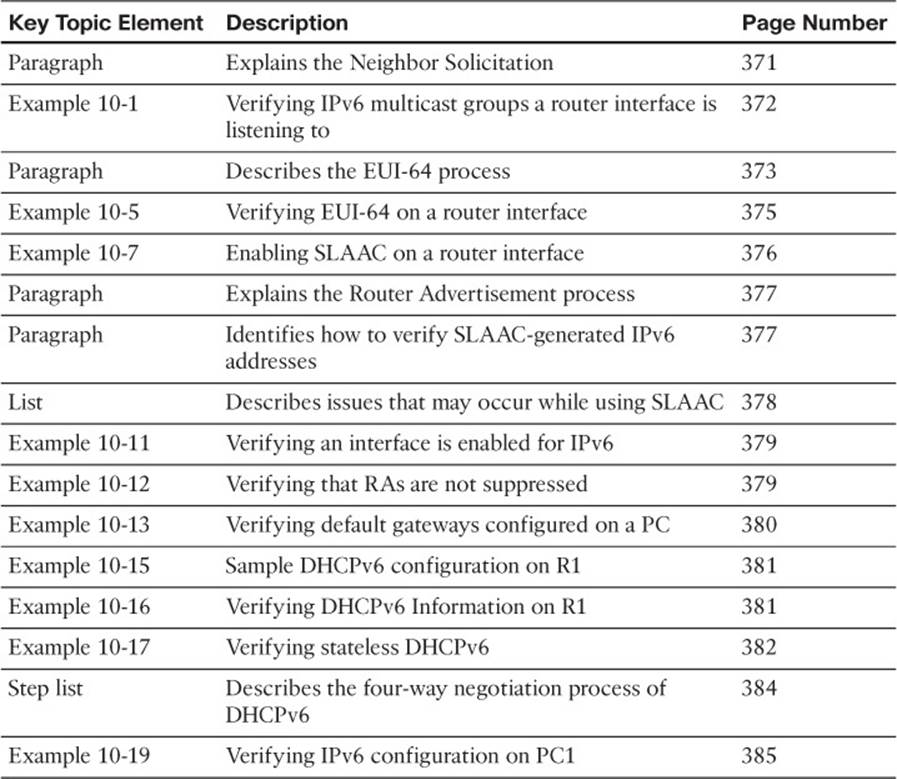
Table 10-3 Key Topics for Chapter 10
Define Key Terms
Define the following key terms from this chapter and check your answers in the glossary:
Neighbor Solicitation
Neighbor Advertisement
Neighbor Discovery
solicited node multicast addresses
EUI-64
stateless autoconfiguration (SLAAC)
stateful DHCPv6
stateless DHCPv6
router solicitation
router advertisement
link-local address
global unicast address
SOLICIT message
ADVERTISE message
REQUEST message
REPLY message
DHCPv6 relay agent
Command Reference to Check Your Memory
This section includes the most important show commands covered in this chapter. It might not be necessary to memorize the complete syntax of every command, but you should be able to remember the basic keywords that are needed.
To test your memory of the commands, cover the right side of Table 10-4 with a piece of paper, read the description on the left side, and then see how much of the command you can remember.
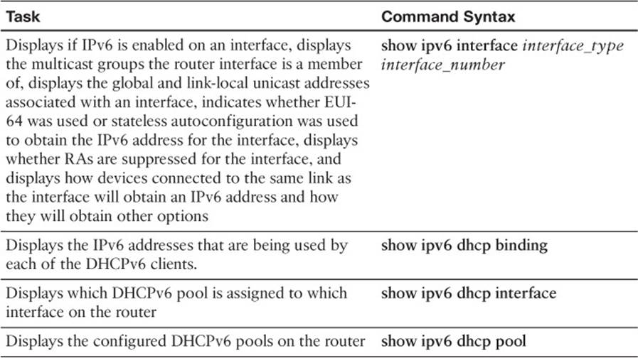
Table 10-4 show Commands
The 300-135 TSHOOT exam focuses on practical, hands-on skills that are used by a networking professional. Therefore, you should be able to identify the commands needed to successfully troubleshoot the topic covered in this chapter.
All materials on the site are licensed Creative Commons Attribution-Sharealike 3.0 Unported CC BY-SA 3.0 & GNU Free Documentation License (GFDL)
If you are the copyright holder of any material contained on our site and intend to remove it, please contact our site administrator for approval.
© 2016-2026 All site design rights belong to S.Y.A.