CCNP Routing and Switching TSHOOT 300-135 Official Cert Guide (2015)
Part III. Troubleshooting Router Features
Chapter 12. Troubleshooting Basic IPv4/IPv6 Routing and GRE Tunnels
This chapter covers the following topics:
![]() Packet-Forwarding Process: This section covers the processes that are involved during the packet-forwarding process and the commands that you can use while troubleshooting issues related to the packet-forwarding process.
Packet-Forwarding Process: This section covers the processes that are involved during the packet-forwarding process and the commands that you can use while troubleshooting issues related to the packet-forwarding process.
![]() Troubleshooting Routing Information Sources: This section covers how a router can learn from multiple sources and how it chooses which source is the most reliable. You will also learn how you can identify the administrative distance associated with a route.
Troubleshooting Routing Information Sources: This section covers how a router can learn from multiple sources and how it chooses which source is the most reliable. You will also learn how you can identify the administrative distance associated with a route.
![]() Troubleshooting Static Routes: This section explains how IPv4 and IPv6 static routes are created. You will also learn the key characteristics of each and how a misconfiguration can cause suboptimal routing or routing loops.
Troubleshooting Static Routes: This section explains how IPv4 and IPv6 static routes are created. You will also learn the key characteristics of each and how a misconfiguration can cause suboptimal routing or routing loops.
![]() Static Routing Trouble Tickets: This section provides trouble tickets that demonstrate how you can use a structured troubleshooting process to solve a reported problem.
Static Routing Trouble Tickets: This section provides trouble tickets that demonstrate how you can use a structured troubleshooting process to solve a reported problem.
![]() Troubleshooting GRE Tunnels: This section explains how to configure a GRE tunnel over an IPv4 network to transport IPv4 and IPv6 traffic so that you are able to troubleshoot misconfiguration issues with GRE tunnels. You will also discover the benefits of using IPsec with GRE tunnels for security.
Troubleshooting GRE Tunnels: This section explains how to configure a GRE tunnel over an IPv4 network to transport IPv4 and IPv6 traffic so that you are able to troubleshoot misconfiguration issues with GRE tunnels. You will also discover the benefits of using IPsec with GRE tunnels for security.
Before you can explore how to troubleshoot static routing or dynamic routing, you need a solid understanding of the packet-delivery process (also known as the routing process). This is the process that a router goes through when a packet arrives at an ingress interface and needs to be packet switched to an egress interface. It does not matter whether the packet is an IPv4 or IPv6 packet. The router will go through the same steps to successfully take a packet from in ingress interface and packet switch it to the egress interface.
As a troubleshooter, you also need to be familiar with how a router populates the routing table with “the best” routes. What classifies those routes as the best? Is an Enhanced Interior Gateway Routing Protocol (EIGRP)-learned route better than a static route? What about an Open Shortest Path First (OSPF)-learned route or a Border Gateway Protocol (BGP)-learned route? How do they compare to the other sources of routing information. When multiple sources provide the same routing information, as a troubleshooter you need to be able to identify why the router made the decision it made.
Static routes are part of every network. However, because they are manually configured, they are prone to human error, which can produce suboptimal routing or routing loops. As a troubleshooter, you need to be able to identify issues related to static routes.
Also, it is common to take one protocol like IPv6 and transport it over another protocol like IPv4. This is accomplished by using a tunneling protocol such as generic routing encapsulation (GRE). GRE is used to encapsulate various types of network layer packets inside a transport protocol (GRE) so that they can be transported over an IP network. Therefore, you need to be able to troubleshoot issues related to GRE tunnels.
This chapter covers the packet-delivery process and the various commands that you can use to troubleshoot issues related to the process. You will learn how a router chooses which sources of routing information are more believable so that only the best routes are in the routing table. You will also learn how to recognize and troubleshoot issues related to static routing and GRE tunnels.
“Do I Know This Already?” Quiz
The “Do I Know This Already?” quiz allows you to assess whether you should read this entire chapter thoroughly or jump to the “Exam Preparation Tasks” section. If you are in doubt about your answers to these questions or your own assessment of your knowledge of the topics, read the entire chapter. Table 12-1 lists the major headings in this chapter and their corresponding “Do I Know This Already?” quiz questions. You can find the answers in Appendix A, “Answers to the ‘Do I Know This Already?’ Quizzes.”
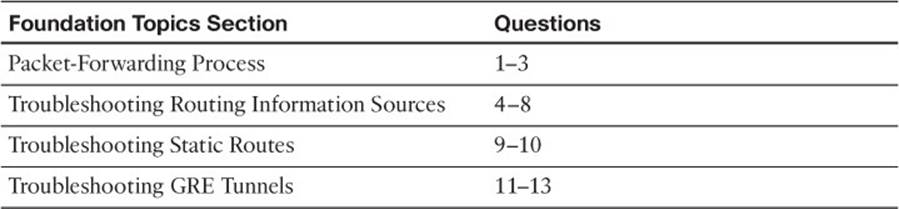
Table 12-1 “Do I Know This Already?” Section-to-Question Mapping
Caution
The goal of self-assessment is to gauge your mastery of the topics in this chapter. If you do not know the answer to a question or are only partially sure of the answer, you should mark that question as wrong for purposes of the self-assessment. Giving yourself credit for an answer that you correctly guess skews your self-assessment results and might provide you with a false sense of security.
1. Which two data structures does a router use during the packet-forwarding process?
a. Routing table
b. Layer 3 to Layer 2 mapping table
c. Topology table
d. Link-state database
2. Which two data structures reside at the routers data plane?
a. IP routing table
b. ARP cache
c. Forwarding Information Base
d. Adjacency table
3. Which command enables you to verify routes in the FIB?
a. show ip route
b. show ip arp
c. show ip cef
d. show adjacency detail
4. Which are capable of populating a routing protocols data structure, such as the EIGRP topology table? (Choose three answers.)
a. Updates from a neighbor
b. Redistributed routes
c. Interfaces enabled for the routing process
d. Static routes
5. Which of the following has the lowest default administrative distance?
a. OSPF
b. EIGRP (internal)
c. RIP
d. eBGP
6. What is the default administrative distance of an OSPF intra-area route?
a. 90
b. 110
c. 115
d. 120
7. What is the default administrative distance of a static route?
a. 0
b. 1
c. 5
d. 20
8. How can you create a floating static route?
a. Provide the static route with a metric higher than the preferred source of the route
b. Provide the static route with a metric lower than the preferred source of the route
c. Provide the static route with an AD higher than the preferred source of the route
d. Provide the static route with an AD lower than the preferred source of the route
9. What occurs when you create an IPv4 static route with an Ethernet interface designated instead of a next hop IP address?
a. The router ARPs for the MAC address of the directly connected routers IP address.
b. The router forwards the packet with a destination MAC address of FFFF:FFFF:FFFF.
c. The router ARPs for the MAC address of the IP address in the source of the packet.
d. The router ARPs for the MAC address of the IP address in the destination of the packet.
10. What occurs when you create an IPv6 static route with a global unicast address as the next hop?
a. The router ARPs for the MAC address of the directly connected routers IP address.
b. The router forwards the packet with a destination MAC address of FFFF:FFFF:FFFF.
c. The router uses NDP to determine the MAC address associated with the global unicast address.
d. The router uses NDP to determine the MAC address associated with the destination IPv6 address in the packet.
11. Which statements are true about GRE tunnels?
a. The original packet is encapsulated in a GRE header only.
b. The original packet is encapsulated in a GRE header, and then a new IP header is added.
c. The original packet is encapsulated in an IP header, and then a GRE header is added.
d. The original packet header is rewritten by the GRE header.
12. When creating a virtual tunnel interface, what is the default tunnel mode?
a. GRE/IP
b. GRE/IPv6
c. IPv6/IP
d. GRE/Multipoint
13. Which of the following are true about IPsec transport mode? (Choose two answers.)
a. It creates a new tunnel IP packet.
b. It reuses the GRE IP header, which reduces overhead.
c. It encrypts the original IP packet, the GRE header, and the GRE IP header.
d. It encrypts the original IP packet and the GRE header only.
Foundation Topics
Packet-Forwarding Process
When troubleshooting connectivity issues for an IP-based network, the network layer (Layer 3) of the OSI reference model is often an appropriate place to begin your troubleshooting efforts (divide-and-conquer method). For example, if you are experiencing connectivity issues between two hosts on a network, you could check Layer 3 by pinging between the hosts. If the pings are successful, you can conclude that the issue resides at upper layers of the OSI reference model (Layers 4–7). However, if the pings fail, you can focus your troubleshooting efforts on Layers 1–3. If you ultimately determine that there is a problem at Layer 3, your efforts may be centered on the packet-forwarding process of a router.
This section discusses the packet-forwarding process and the commands that you can use to verify the entries in the data structures that are used for this process. It also provides you with a collection of Cisco IOS Software commands that could prove to be useful when troubleshooting-related issues.
Reviewing Layer 3 Packet-Forwarding Process
To review basic routing processes, consider Figure 12-1. In this topology, PC1 needs to access HTTP resources on Server1. Notice that PC1 and Server1 are on different networks. So, the question becomes, how does a packet from a source IP address of 192.168.1.2 get routed to a destination IP address of 192.168.3.2?
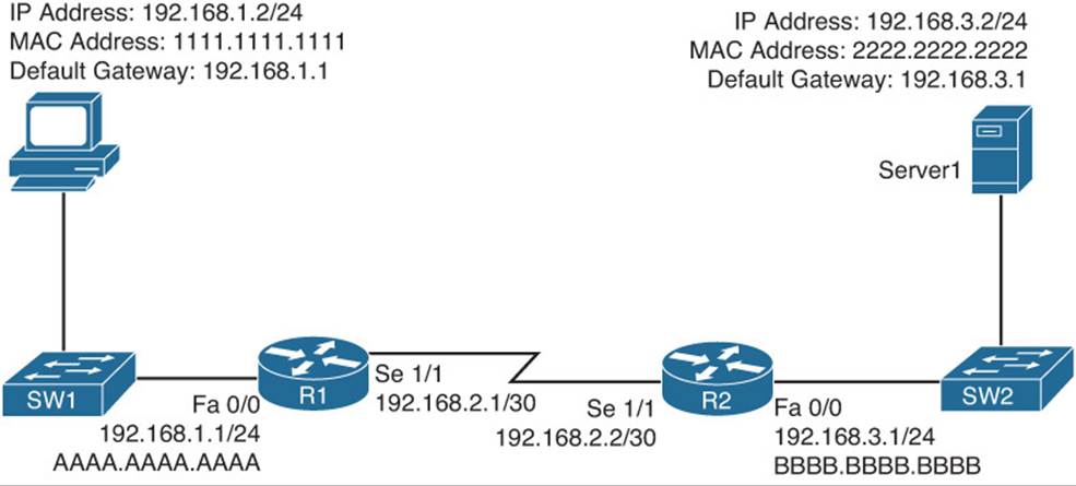
Figure 12-1 Basic Routing Topology
Consider the following walkthrough of this process, step by step:
Step 1. PC1 compares its IP address and subnet mask of 192.168.1.2/24 with the destination IP address 192.168.3.2, as discussed in Chapter 9, “Troubleshooting IPv4 Addressing and Addressing Technologies.” PC1 determines the network portion of its own IP address. It then compares these binary bits with the same binary bits of the destination address. If they are the same, the destination is on the same subnet. If they differ, the destination is on a remote subnet. PC1 concludes that the destination IP address resides on a remote subnet in this example. Therefore, PC1 needs to send the frame to its default gateway, which could have been manually configured on PC1 or dynamically learned via Dynamic Host Configuration Protocol (DHCP). In this example, PC1 has a default gateway of 192.168.1.1 (that is, router R1). To construct a proper Layer 2 frame, PC1 needs the MAC address of the frame’s destination, which is PC1’s default gateway in this example. If the MAC address is not in PC1’s Address Resolution Protocol (ARP) cache, PC1 uses ARP to discover it. Once PC1 receives an ARP reply from router R1, PC1 adds router R1’s MAC address to its ARP cache. PC1 now sends its data destined for Server1 in a frame addressed to R1, as shown in Figure 12-2.
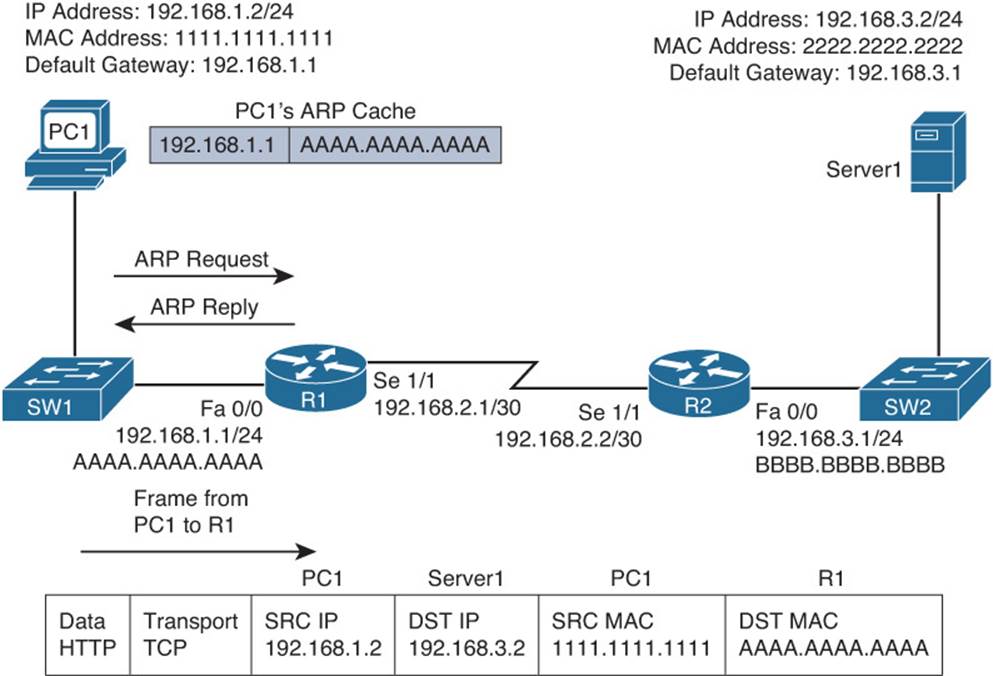
Figure 12-2 Basic Routing Step 1
Step 2. Router R1 receives the frame sent from PC1, and because the destination MAC is R1’s, R1 tears off the Layer 2 header and interrogates the IP (Layer 3) header. An IP header contains a time-to-live (TTL) field, which is decremented once for each router hop. Therefore, router R1 decrements the packet’s TTL field. If the value in the TTL field is reduced to zero, the router discards the packet and sends a time-exceeded Internet Control Message Protocol (ICMP) message back to the source. Assuming the TTL is not decremented to zero, router R1 checks its routing table to determine the best path to reach the IP address 192.168.3.2. In this example, router R1’s routing table has an entry stating that network 192.168.3.0/24 is accessible via interface Serial 1/1. Note that ARPs are not required for serial interfaces because these interface types do not have MAC addresses. Therefore, router R1 forwards the frame out of its Serial 1/1 interface, as shown in Figure 12-3, using the PPP Layer 2 framing header.
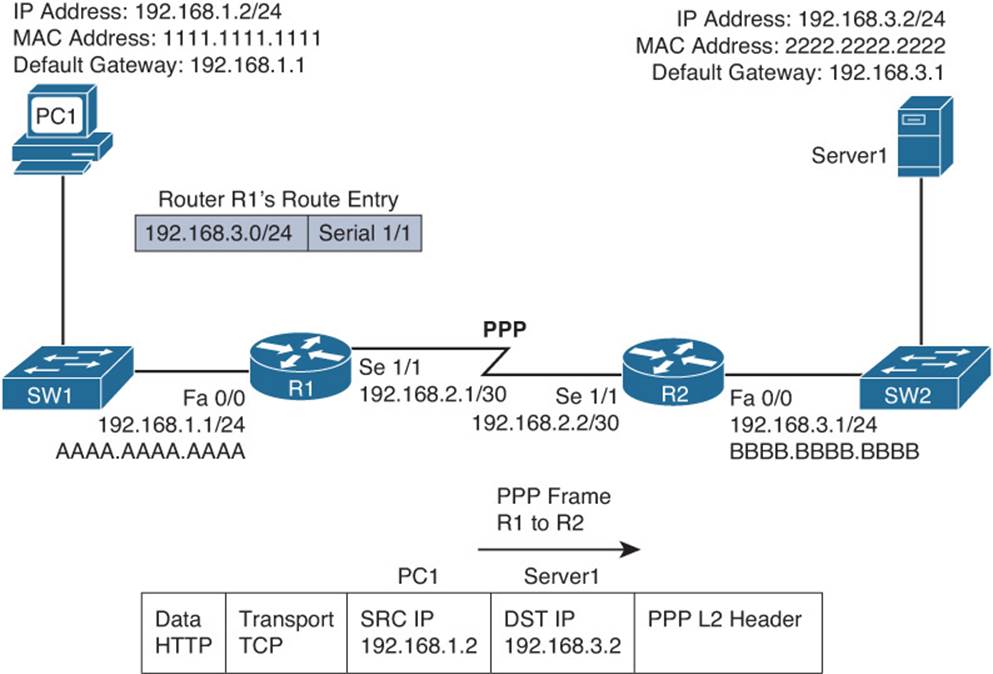
Figure 12-3 Basic Routing Step 2
Step 3. When router R2 receives the frame, it removes the PPP header, and then decrements the TTL in the IP header, just as router R1 did. Again, assuming the TTL did not get decremented to zero, router R2 interrogates the IP header to determine the destination network. In this case, the destination network of 192.168.3.0/24 is directly attached to router R2’s Fast Ethernet 0/0 interface. Similar to how PC1 sent out an ARP request to determine the MAC address of its default gateway, router R2 sends an ARP request to determine the MAC address of Server1 if it is not already known in the ARP cache. Once an ARP reply is received from Server1, router R2 forwards the frame out of its Fast Ethernet 0/0 interface to Server1, as shown in Figure 12-4.
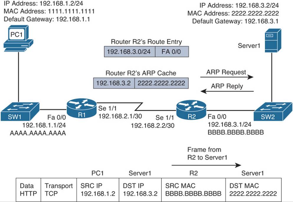
Figure 12-4 Basic Routing Step 3
The previous steps identified two router data structures:

![]() IP routing table: When a router needed to route an IP packet, it consulted its IP routing table to find the best match. The best match is the route that has the longest prefix. For example, suppose that a router has a routing entry for network 10.0.0.0/8, 10.1.1.0/24, and 10.1.1.0/26. Also, suppose that the router is trying to forward a packet with the destination IP address 10.1.1.10. The router would select the 10.1.1.0/26 route entry as the best match for 10.1.1.10 because that route entry has the longest prefix of /26 (matches the most number of bits).
IP routing table: When a router needed to route an IP packet, it consulted its IP routing table to find the best match. The best match is the route that has the longest prefix. For example, suppose that a router has a routing entry for network 10.0.0.0/8, 10.1.1.0/24, and 10.1.1.0/26. Also, suppose that the router is trying to forward a packet with the destination IP address 10.1.1.10. The router would select the 10.1.1.0/26 route entry as the best match for 10.1.1.10 because that route entry has the longest prefix of /26 (matches the most number of bits).
![]() Layer 3 to Layer 2 mapping table: In the previous figure, router R2’s ARP cache contained Layer 3 to Layer 2 mapping information. Specifically, the ARP cache had a mapping that said a MAC address of 2222.2222.2222 corresponded to an IP address of 192.168.3.2. An ARP cache is the Layer 3 to Layer 2 mapping data structure used for Ethernet-based networks, but similar data structures are used for Multipoint Frame Relay networks and dynamic multipoint virtual private networks (DMVPNs). However, for point-to-point links such as PPP or HDLC, because there is only one other possible device connected to the other end of the link, no mapping information is needed to determine the next-hop device.
Layer 3 to Layer 2 mapping table: In the previous figure, router R2’s ARP cache contained Layer 3 to Layer 2 mapping information. Specifically, the ARP cache had a mapping that said a MAC address of 2222.2222.2222 corresponded to an IP address of 192.168.3.2. An ARP cache is the Layer 3 to Layer 2 mapping data structure used for Ethernet-based networks, but similar data structures are used for Multipoint Frame Relay networks and dynamic multipoint virtual private networks (DMVPNs). However, for point-to-point links such as PPP or HDLC, because there is only one other possible device connected to the other end of the link, no mapping information is needed to determine the next-hop device.
Continually querying a router’s routing table and its Layer 3 to Layer 2 mapping data structure (for example, an ARP cache) is less than efficient. Fortunately, Cisco Express Forwarding (CEF), as introduced in Chapter 3, “Troubleshooting Device Performance,” makes lookups much more efficient. CEF gleans its information from the router’s IP routing table and Layer 3 to Layer 2 mapping tables. Then, CEF’s data structures can be referenced when forwarding packets. The two primary CEF data structures are as follows:
![]() Forwarding Information Base (FIB): The FIB contains Layer 3 information, similar to the information found in an IP routing table. In addition, an FIB contains information about multicast routes and directly connected hosts.
Forwarding Information Base (FIB): The FIB contains Layer 3 information, similar to the information found in an IP routing table. In addition, an FIB contains information about multicast routes and directly connected hosts.
![]() Adjacency table: When a router is performing a route lookup using CEF, the FIB references an entry in the adjacency table. The adjacency table entry contains the frame header information required by the router to properly form a frame. Therefore, an egress interface and a next-hop MAC address would be in an adjacency entry for a multipoint interface, whereas a point-to-point interface would require only egress interface information.
Adjacency table: When a router is performing a route lookup using CEF, the FIB references an entry in the adjacency table. The adjacency table entry contains the frame header information required by the router to properly form a frame. Therefore, an egress interface and a next-hop MAC address would be in an adjacency entry for a multipoint interface, whereas a point-to-point interface would require only egress interface information.
As a reference, Figure 12-5 shows the router data structures previously discussed.
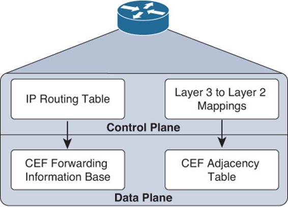
Figure 12-5 A Router’s Data Structures
Troubleshooting the Packet-Forwarding Process
When troubleshooting packet-forwarding issues, you will examine a router’s IP routing table. If the traffic’s observed behavior is not conforming to information in the IP routing table, remember that the IP routing table is maintained by a router’s control plane and is used to build the tables at the data plane. CEF is operating in the data plane and uses the FIB. Therefore, you want to view the CEF data structures (that is, the FIB and the adjacency table) that contain all the information required to make packet-forwarding decisions.
Example 12-1 provides sample output from the show ip route [ip_address] command. The output shows that the next-hop IP address to reach an IP address of 192.168.1.11 is 192.168.0.11, which is accessible via interface Fast Ethernet 0/0. Because this information is coming from the control plane, it includes information about the routing protocol, which is OSPF in this case.
Example 12-1 show ip route ip_address Command Output
Router#show ip route 192.168.1.11
Routing entry for 192.168.1.0/24
Known via "ospf 1", distance 110, metric 11, type intra area
Last update from 192.168.0.11 on FastEthernet0/0, 00:06:45 ago
Routing Descriptor Blocks:
192.168.0.11, from 10.1.1.1, 00:06:45 ago, via FastEthernet0/0
Route metric is 11, traffic share count is 1
Example 12-2 provides sample output from the show ip route ip_address subnet_mask command. The output indicates that the entire network 192.168.1.0/24 is accessible out of interface Fast Ethernet 0/0, with a next-hop IP address of 192.168.0.11.
Example 12-2 show ip route ip_address subnet_mask Command Output
Router#show ip route 192.168.1.0 255.255.255.0
Routing entry for 192.168.1.0/24
Known via "ospf 1", distance 110, metric 11, type intra area
Last update from 192.168.0.11 on FastEthernet0/0, 00:06:57 ago
Routing Descriptor Blocks:
192.168.0.11, from 10.1.1.1, 00:06:57 ago, via FastEthernet0/0
Route metric is 11, traffic share count is 1
Example 12-3 provides sample output from the show ip route ip_address subnet_mask longer-prefixes command, with and without the longer-prefixes option. Notice that the router responds that the subnet 172.16.0.0 255.255.0.0 is not in the IP routing table. However, after adding thelonger-prefixes option, two routes are displayed, because these routes are subnets of the 172.16.0.0/16 network.
Example 12-3 show ip route ip_address subnet_mask longer-prefixes Command Output
Router#show ip route 172.16.0.0 255.255.0.0
% Subnet not in table
R2#show ip route 172.16.0.0 255.255.0.0 longer-prefixes
Codes: C - connected, S - static, R - RIP, M - mobile, B - BGP
D - EIGRP, EX - EIGRP external, O - OSPF, IA - OSPF inter area
N1 - OSPF NSSA external type 1, N2 - OSPF NSSA external type 2
E1 - OSPF external type 1, E2 - OSPF external type 2
i - IS-IS, su - IS-IS summary, L1 - IS-IS level-1, L2 - IS-IS level-2
ia - IS-IS inter area, * - candidate default, U - per-user static route
- ODR, P - periodic downloaded static route
Gateway of last resort is not set
172.16.0.0/30 is subnetted, 2 subnets
C 172.16.1.0 is directly connected, Serial1/0.1
C 172.16.2.0 is directly connected, Serial1/0.2
Example 12-4 provides sample output from the show ip cef ip_address command. The output indicates that, according to CEF, an IP address of 192.168.1.11 is accessible out of interface Fast Ethernet 0/0, with a next-hop IP address of 192.168.0.11.
Example 12-4 show ip cef ip_address Command Output
Router#show ip cef 192.168.1.11
192.168.1.0/24, version 42, epoch 0, cached adjacency 192.168.0.11
0 packets, 0 bytes
via 192.168.0.11, FastEthernet0/0, 0 dependencies
next hop 192.168.0.11, FastEthernet0/0
valid cached adjacency
Example 12-5 provides sample output from the show ip cef ip_address subnet_mask command. The output indicates that network 192.168.1.0/24 is accessible off of interface Fast Ethernet 0/0, with a next-hop IP address of 192.168.0.11.
Example 12-5 show ip cef ip_address subnet_mask Command Output
Router#show ip cef 192.168.1.0 255.255.255.0
192.168.1.0/24, version 42, epoch 0, cached adjacency 192.168.0.11
0 packets, 0 bytes
via 192.168.0.11, FastEthernet0/0, 0 dependencies
next hop 192.168.0.11, FastEthernet0/0
valid cached adjacency
Example 12-6 provides sample output from the show ip cef exact-route source_address destination_address command. The output indicates that a packet sourced from an IP address of 10.2.2.2 and destined for an IP address of 192.168.1.11 will be sent out of interface Fast Ethernet 0/0 to a next-hop IP address of 192.168.0.11.
Example 12-6 show ip cef exact-route source_address destination_address Command Output
Router#show ip cef exact-route 10.2.2.2 192.168.1.11
10.2.2.2 -> 192.168.1.11 : FastEthernet0/0 (next hop 192.168.0.11)
For a multipoint interface such as point-to-multipoint Frame Relay or Ethernet, after a router knows the next-hop address for a packet, it needs appropriate Layer 2 information (for example, next-hop MAC address, or data-link connection identifier [DLCI]) to properly construct a frame.Example 12-7 provides sample output from the show ip arp command, which displays the ARP cache that is stored in the control plane on a router. The output shows the learned or configured MAC addresses along with their associated IP addresses.
Example 12-7 show ip arp Command Output
Router#show ip arp
Protocol Address Age (min) Hardware Addr Type Interface
Internet 192.168.0.11 0 0009.b7fa.d1e1 ARPA FastEthernet0/0
Internet 192.168.0.22 - c001.0f70.0000 ARPA FastEthernet0/0
Example 12-8 provides sample output from the show frame-relay map command. The output shows the Frame Relay interfaces, the corresponding DLCIs associated with the interfaces, and the next-hop IP address that is reachable out the interface using the permanent virtual circuit (PVC)associated with the listed DLCI. In this case, if R2 needs to send data to the next-hop IP address 172.16.33.6, it would use the PVC associated with DLCI 406 to get there.
Example 12-8 show frame-relay map Command Output
Router#show frame-relay map
Serial1/0 (up): ip 172.16.33.5 dlci 405(0x195,0x6450), static,broadcast,
CISCO, status defined, active
Serial1/0 (up): ip 172.16.33.6 dlci 406(0x196,0x6460), static,broadcast,
CISCO, status defined, active
Example 12-9 provides sample output from the show ip nhrp command. This command displays the Next Hop Resolution Protocol cache that is used with DMVPNs. In this example, if a packet needs to be sent to the 192.168.255.2 next-hop IP address, the nonbroadcast multiaccess (NBMA) address of 198.51.100.2 is used to reach it.
Example 12-9 show ip nhrp Command Output
HUBRouter#show ip nhrp
192.168.255.2/32 via 192.168.255.2
Tunnel0 created 00:02:35, expire 01:57:25
Type: dynamic, Flags: unique registered
NBMA address: 198.51.100.2
192.168.255.3/32 via 192.168.255.3
Tunnel0 created 00:02:36, expire 01:57:23
Type: dynamic, Flags: unique registered
NBMA address: 203.0.113.2
Example 12-10 provides sample output from the show adjacency detail command. The output shows the CEF information used to construct frame headers needed to reach the next-hop IP addresses through the various router interfaces. Notice the value 64510800 for Serial 1/0. This is a hexadecimal representation of information that is needed by the router to successfully forward the packet to the next hop IP address 172.16.33.5, including the DLCI of 405. Notice the value CA1B01C4001CCA1C164000540800 for Fast Ethernet 3/0. This is the destination MAC, source MAC, and the EtherType code for an Ethernet frame. The first 12 hex values are the destination MAC, the next 12 are the source MAC, and 0800 is the IPv4 EtherType code.
Example 12-10 show adjacency detail Command Output
Router#show adjacency detail
Protocol Interface Address
IP Serial1/0 172.16.33.5(7)
0 packets, 0 bytes
epoch 0
sourced in sev-epoch 1
Encap length 4
64510800
FR-MAP
IP Serial1/0 172.16.33.6(7)
0 packets, 0 bytes
epoch 0
sourced in sev-epoch 1
Encap length 4
64610800
FR-MAP
IP FastEthernet3/0 203.0.113.1(7)
0 packets, 0 bytes
epoch 0
sourced in sev-epoch 1
Encap length 14
CA1B01C4001CCA1C164000540800
L2 destination address byte offset 0
L2 destination address byte length 6
Link-type after encap: ip
ARP
Troubleshooting Routing Information Sources
When designing a routed network, you have many options to choose from when determining what will be the source of routing information: connected, static, EIGRP, OSPF, BGP, to name a few. With all these different options, you need to be able to recognize what is more trustworthy (believable). This is extremely important when you are using multiple sources because only one source of information can be used to populate the routing table for any given route. As a result, it is important as a troubleshooter to understand how the best source of route information is determined and placed in the routing table.
This section explains which sources of route information are the most believable and how the routing table interacts with various data structures to populate itself with the best information.
Data Structures and the Routing Table
To better troubleshoot routing information sources, consider, generically, how dynamic routing protocols’ data structures interact with a router’s IP routing table. Figure 12-6 shows the interaction between the data structures of an IP routing protocol and a router’s IP routing table.
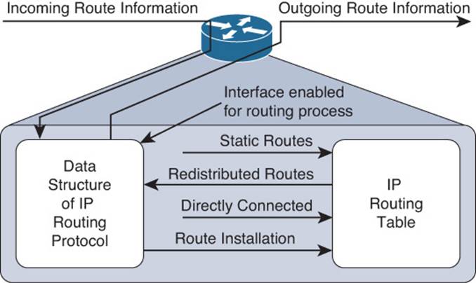
Figure 12-6 Interaction Between the IP Routing Table and a Routing Protocol Data Structure
As a router receives route information from a neighboring router, the information is stored in the data structures of the IP routing protocol and analyzed by the routing protocol to determine the best path based on metrics. An IP routing protocol’s data structure can also be populated by the local router. For example, a router might be configured for route redistribution, where route information is redistributed from the routing table into the IP routing protocols data structure. The router might be configured to have specific interfaces participate in an IP routing protocol process. Therefore, the network that the interface belongs to is placed into the routing protocol data structure as well.
However, what goes in the routing table? Reviewing Figure 12-6 again, you can see that the routing protocol data structure can populate the routing table, a directly connected route can populate the routing table, and static routes can populate the routing table. These are all known as sources of routing information.
Sources of Route Information
Your router could conceivably receive route information from the following routing sources all at the same time:
![]() Connected interface
Connected interface
![]() Static route
Static route
![]() RIP
RIP
![]() EIGRP
EIGRP
![]() OSPF
OSPF
![]() BGP
BGP
If the route information received from all these sources is for different destination networks, each one will be used for its respectively learned destination networks and be placed in the routing table. However, what if the route received from RIP and OSPF were the exact same? For example, both protocols have informed the router about the 10.1.1.0/24 network. How does the router choose which is the most believable, or the best source of routing information? It cannot use both; it has to pick one and install that information in the routing table.
Routing information sources have each been assigned an administrative distance (AD). An administrative distance of a routing information source can be thought of as the believability or trustworthiness of that routing source when comparing it to the other routing information sources. Table 12-2 lists the default ADs of routing information sources. The lower the AD, the more preferred the source of information.
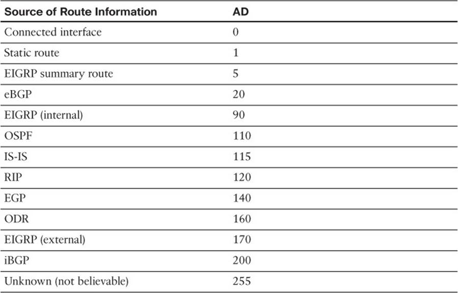
Table 12-2 Default Administrative Distance of Route Sources
For instance, RIP has a default AD of 120, whereas OSPF has a default AD of 110. Therefore, if both RIP and OSPF have knowledge of a route to a specific network (10.1.1.0/24 as an example), the OSPF route would be injected into the router’s IP routing table because OSPF has a more believable AD. Therefore, the best route selected by an IP routing protocol’s data structure is only a candidate to be injected into the router’s IP routing table. The route is only injected into the routing table if the routing table concludes that it came from the best routing source. As you will see in later chapters when you troubleshoot specific routing protocols, routes might be missing in the routing table from a specific routing protocol, or suboptimal routing may be occurring because a different routing source with a lower AD is being used.
You can verify the AD of a route in the routing table by using the show ip route ip_address command as shown in Example 12-11. You can see in the example that the route to 10.1.1.0 has an AD of 0 and the route to 10.1.23.0 has an AD of 90.
Example 12-11 Verifying the Administrative Distance of a Route in the Routing Table
R1#show ip route 10.1.1.0
Routing entry for 10.1.1.0/26
Known via "connected", distance 0, metric 0 (connected, via interface)
Redistributing via eigrp 100
Routing Descriptor Blocks:
directly connected, via GigabitEthernet1/0
Route metric is 0, traffic share count is 1
R1#show ip route 10.1.23.0
Routing entry for 10.1.23.0/24
Known via "eigrp 100", distance 90, metric 3072, type internal
Redistributing via eigrp 100
Last update from 10.1.13.3 on GigabitEthernet2/0, 09:42:20 ago
Routing Descriptor Blocks:
10.1.13.3, from 10.1.13.3, 09:42:20 ago, via GigabitEthernet2/0
Route metric is 3072, traffic share count is 1
Total delay is 20 microseconds, minimum bandwidth is 1000000 Kbit
Reliability 255/255, minimum MTU 1500 bytes
Loading 1/255, Hops 1
If you ever need to make sure that the route information or subset of route information received from a particular source is never used, you can change the AD of specific routes or all routes from that source to 255, which means “do not believe.”
AD can also be used to manipulate path selection. For example you may have two different paths to the same destination learned from two different sources (for example, EIGRP and a static route). In this case, the static route is preferred. However, this static route may be pointing to a backup link that is slower than the EIGRP path. Therefore, you want the EIGRP path to be installed in the routing table because the static route is causing suboptimal routing. But, you are not allowed to remove the static route. To solve this issue, you can create a floating static route. This static route has a higher AD than the preferred route. Because we want EIGRP to be preferred, we modify the static route so that it has an AD higher than EIGRP, which is 90. As a result, the EIGRP-learned route is installed in the routing table, and the static route will be installed only if the EIGRP-learned route goes away.
Troubleshooting Static Routes
Static routes are manually configured by administrators, and by default are the second most trustworthy source of routing information, with an AD of 1. They allow an administrator to precisely control how to route packets for a particular destination. This section discusses the syntax of IPv4 and IPv6 static routes and explains what to look for while troubleshooting.
IPv4 Static Routes
To create an IPv4 static route, you use the ip route prefix mask {ip_address | interface_type interface_number} [distance] command in global configuration mode. Example 12-12 displays the configuration of a static route on R1, as shown in Figure 12-7. The static route is training R1 about the 10.1.3.0/24 network. To get to the network, it is reachable via the next-hop address of 10.1.12.2, which is R2, and it has been assigned an AD of 8. (The default is 1.)
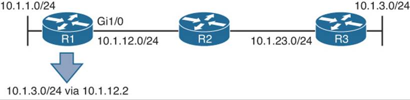
Figure 12-7 Configuring a Static Route on R1 with Next-Hop Option
Example 12-12 Configuring a Static Route on R1 with Next-Hop Option
R1#config t
Enter configuration commands, one per line. End with CNTL/Z.
R1(config)#ip route 10.1.3.0 255.255.255.0 10.1.12.2 8
Example 12-13, which shows the output of show ip route static on R1, indicates that the 10.1.3.0/24 network was learned by a static route, it is reachable via the next-hop IP address of 10.1.12.2, it has an AD of 8, and the metric is 0 because there is no way to know how far the destination truly is like a dynamic routing protocol does.
Example 12-13 Verifying a Static Route on R1
R1#show ip route static
Codes: L - local, C - connected, S - static, R - RIP, M - mobile, B - BGP
...output omitted...
10.0.0.0/8 is variably subnetted, 7 subnets, 2 masks
S 10.1.3.0/24 [8/0] via 10.1.12.2
When troubleshooting IPv4 static routes, you need to be able to recognize why the static route may not be providing the results you want. For example, are the network and mask accurate? If either of these is incorrect, your static route will not route the packets you are expecting it to route. The router might drop packets because it does not match the static route or any other route. It might end up forwarding packets via the default route, which may be pointing the wrong way. In addition, if the static route includes networks that it should not, you could be routing packets the wrong way.
Consider this: If you were to configure the following static route on R2 in Figure 12-7, ip route 10.1.3.0 255.255.255.0 10.1.12.1, packets destined to 10.1.3.0 would be sent to R1, which is the wrong way. However, notice in Example 12-13 that R1 points to R2 (10.1.12.2) for the network 10.1.3.0/24. Therefore, R1 and R2 will simply bounce packets back and forth that are destined for 10.1.3.0/24 until the TTL expires.
As you can see, the next-hop IP address is a very important parameter for the static route. It tells the local router where to send the packet. For instance, in Example 12-13, the next hop is 10.1.12.2. Therefore, a packet destined to 10.1.3.0 has to go to 10.1.12.2 next. R1 now does a recursive lookup in the routing table for 10.1.12.2 to determine how to reach it, as shown in Example 12-14. This example displays the output of the show ip route 10.1.12.2 command on R1. You can see that 10.1.12.2 is directly connected out Gigabit Ethernet 1/0.
Example 12-14 Recursive Lookup on R1 for Next-Hop Address
R1#show ip route 10.1.12.2
Routing entry for 10.1.12.0/24
Known via "connected", distance 0, metric 0 (connected, via interface)
Routing Descriptor Blocks:
directly connected, via GigabitEthernet1/0
Route metric is 0, traffic share count is 1
Because the exit interface to reach 10.1.12.2 is Gigabit Ethernet 1/0, the Ethernet frame requires a source and destination MAC address. As a result, R1 looks in its ARP cache as shown in Example 12-15 and finds the MAC for 10.1.12.2 is ca08.0568.0008.
Example 12-15 MAC Address Lookup in ARP Cache
R1#show ip arp
Protocol Address Age (min) Hardware Addr Type Interface
Internet 10.1.1.1 - ca07.0568.0008 ARPA GigabitEthernet0/0
Internet 10.1.12.1 - ca07.0568.001c ARPA GigabitEthernet1/0
Internet 10.1.12.2 71 ca08.0568.0008 ARPA GigabitEthernet1/0
As you can see in this case, the MAC address of the next-hop address is used for the Layer 2 frame. It is not the MAC address of the IP address in the packet. The benefit of this is that the router only has to find the MAC address of the next-hop once using the ARP process and then store the results in the ARP cache. Now, any packet that has to go to the next-hop of 10.1.12.2 does not require an ARP request to be sent, just a look up in the ARP cache, making the overall routing process more efficient.
Now that we understand the next-hop IP address, there is another option we need to know about. The ip route syntax shown earlier indicated that you can specify an exit interface instead of a next hop IP address. There is a right time and a wrong time to use the exit interface. The right time is when it’s a pure point-to-point interface such as DSL, or Serial. Point-to-Point Ethernet links are not pure point-to-point, they are still multi-access, and since they are Ethernet they require a source and destination MAC address. If you specify an Ethernet interface as the next-hop you will be making your router ARP for the MAC address of every destination IP address in every packet. Let’s look at this.
You configure the following static route on R1: ip route 10.1.3.0 255.255.255.0 gigabit Ethernet 1/0. Example 12-16 displays how the static route appears in the routing table. It states 10.1.3.0/24 is directly connected to Gigabit Ethernet 1/0. But is it? Refer to Figure 12-8 to know for sure. It is clear in Figure 12-8 that 10.1.3.0/24 is not directly connected. But, the way the static route is configured, R1 thinks that it is.
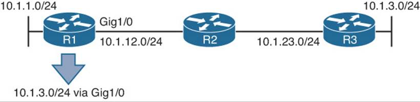
Figure 12-8 Configuring a Static Route on R1 with Exit Interface Option
Example 12-16 Static Route with Exit Interface Specified
R1#show ip route static
...output omitted...
10.0.0.0/8 is variably subnetted, 7 subnets, 2 masks
S 10.1.3.0/24 is directly connected, GigabitEthernet1/0
Imagine users in the 10.1.1.0/24 network are trying to access resources in the 10.1.3.0/24 network. Specifically, they are accessing resources on 10.1.3.1 through 10.1.3.8. R1 receives the packets, and it looks in the routing table and the longest match is the following entry:
S 10.1.3.0/24 is directly connected, GigabitEthernet1/0
R1 believes the network is directly connected; therefore, the destination IP address in the packet is on the network connected to Gig1/0. However, we know better because we have shown in Figure 12-8 that it is not. So, because it is an Ethernet interface, R1 will use ARP to determine the MAC of the IP address in the destination field of the packet. (This is different from what occurred when the next-hop IP address was specified. When the next-hop was specified, the MAC of the next-hop address was used.) Review Example 12-17 now. It displays the ARP cache on R1. Notice that every destination IP address has an entry in the ARP cache. How can that be since ARPs are not forwarded by routers? It is because of Proxy ARP, which is on by default on our routers. Proxy ARP allows a router to respond to ARP requests with its own MAC address if it has a route in the routing table to the IP address in the ARP request. Notice how the MAC addresses listed are all the same. In addition, they match the MAC address of the 10.1.12.2 entry. Therefore, because R2 has a route to reach the IP address of the ARP request, it responds back with its MAC address to use.
Example 12-17 ARP Cache on R1 with R2 Proxy ARP Enabled
R1#show ip arp
Protocol Address Age (min) Hardware Addr Type Interface
Internet 10.1.1.1 - ca07.0568.0008 ARPA GigabitEthernet0/0
Internet 10.1.3.1 0 ca08.0568.0008 ARPA GigabitEthernet1/0
Internet 10.1.3.2 0 ca08.0568.0008 ARPA GigabitEthernet1/0
Internet 10.1.3.3 3 ca08.0568.0008 ARPA GigabitEthernet1/0
Internet 10.1.3.4 0 ca08.0568.0008 ARPA GigabitEthernet1/0
Internet 10.1.3.5 1 ca08.0568.0008 ARPA GigabitEthernet1/0
Internet 10.1.3.6 0 ca08.0568.0008 ARPA GigabitEthernet1/0
Internet 10.1.3.7 0 ca08.0568.0008 ARPA GigabitEthernet1/0
Internet 10.1.3.8 1 ca08.0568.0008 ARPA GigabitEthernet1/0
Internet 10.1.12.1 - ca07.0568.001c ARPA GigabitEthernet1/0
Internet 10.1.12.2 139 ca08.0568.0008 ARPA GigabitEthernet1/0
Example 12-18 shows how you can verify whether Proxy ARP is enabled by using the show ip interfaces command.
Example 12-18 Verifying Whether Proxy ARP Is Enabled
R2#show ip interface gigabitEthernet 0/0
GigabitEthernet0/0 is up, line protocol is up
Internet address is 10.1.12.2/24
Broadcast address is 255.255.255.255
Address determined by non-volatile memory
MTU is 1500 bytes
Helper address is not set
Directed broadcast forwarding is disabled
Multicast reserved groups joined: 224.0.0.5 224.0.0.6
Outgoing access list is not set
Inbound access list is not set
Proxy ARP is enabled
Local Proxy ARP is disabled
Security level is default
Split horizon is enabled
ICMP redirects are always sent
If Proxy ARP was not enabled, the ARP cache on R1 would appear as shown in Example 12-19. Notice how R1 is still sending ARP requests; however, it is not getting any ARP replies. Therefore, it cannot build the Layer 2 frame, and the result is an encapsulation failure, which you would be able to see if you were debugging IP packets.
Example 12-19 ARP Cache on R1 with R2 Proxy ARP Disabled
R1#show ip arp
Protocol Address Age (min) Hardware Addr Type Interface
Internet 10.1.1.1 - ca07.0568.0008 ARPA GigabitEthernet0/0
Internet 10.1.3.1 0 Incomplete ARPA
Internet 10.1.3.2 0 Incomplete ARPA
Internet 10.1.3.3 0 Incomplete ARPA
Internet 10.1.3.4 0 Incomplete ARPA
Internet 10.1.3.5 0 Incomplete ARPA
Internet 10.1.3.6 0 Incomplete ARPA
Internet 10.1.3.7 0 Incomplete ARPA
Internet 10.1.3.8 0 Incomplete ARPA
Internet 10.1.12.1 - ca07.0568.001c ARPA GigabitEthernet1/0
Internet 10.1.12.2 139 ca08.0568.0008 ARPA GigabitEthernet1/0
Because of the fact that R1 will use ARP to determine the MAC address of every destination IP address in every packet, you should never specify an Ethernet interface in a static route. This results in an excessive use of router resources, such as processor and memory, as the control plane gets involved during the forwarding process to determine the appropriate Layer 2 MAC address using ARP.
As you can see, being able to recognize misconfigured static routes and the issues that arise is an important skill to have when troubleshooting because a misconfigured static route will cause traffic to be misrouted or suboptimally routed. In addition, remember that static routes have an AD of 1; therefore, they will be preferred over other sources of routing information to the same destination.
IPv6 Static Routes
To create an IPv6 static route, you use the ipv6 route {ipv6_prefix/prefix_length} {ipv6_address | interface_type interface_number} [administrative_distance] [next_hop_address] command in global configuration mode.
Example 12-20 displays the configuration of a static route on R1, as shown in Figure 12-9. The static route is training R1 about the 2001:DB8:0:3::/64 network. To get to the network, it is reachable via the next-hop address of FE80::2, which is R2’s link-local address, and it has been assigned an AD of 8. (The default is 1.) Notice how the exit Ethernet interface is specified. This is mandatory when using the link-local address as the next-hop because the same link-local address can be used on multiple local router interfaces. In addition, multiple remote router interfaces can have the same link-local address as well. However, as long as the link-local addresses are unique between the devices within the same local network, then communication occurs as intended. If you are using a global unicast address as the next hop, you do not have to specify the exit interface.
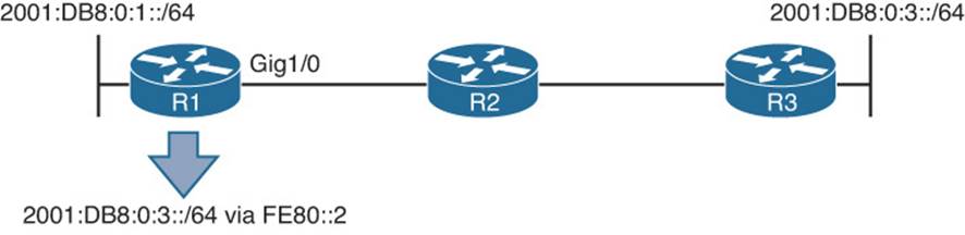
Figure 12-9 Configuring an IPv6 Static Route on R1 with Next-Hop Option
Example 12-20 Configuring an IPv6 Static Route on R1 with Next-Hop Option
R1#config t
Enter configuration commands, one per line. End with CNTL/Z.
R1(config)#ipv6 route 2001:DB8:0:3::/64 gigabitEthernet 1/0 FE80::2 8
Example 12-21, which shows the output of show ipv6 route static on R1, indicates that the 2001:DB8:0:3::/64 network was learned by a static route, it is reachable via the next-hop IP address of FE80::2, it has an AD of 8, and the metric is 0 because there is no way to know how far the destination truly is like a dynamic routing protocol does.
Example 12-21 Verifying an IPv6 Static Route on R1
R1#show ipv6 route static
...output omitted...
S 2001:DB8:0:3::/64 [8/0]
via FE80::2, GigabitEthernet1/0
Now recall that there are no broadcasts with IPv6. Therefore, IPv6 does not use ARP. It uses NDP (Neighbor Discovery Protocol), which is multicast based, to determine a neighboring devices MAC address. In this case, if R1 needs to route packets to 2001:DB8:0:3::/64, the routing table says to use the next-hop FE80::2, which is out Gig1/0. Therefore, it consults its IPv6 neighbor table, as shown in Example 12-22, to determine whether there is a MAC address for FE80::2 out Gig 1/0. It is imperative that the table has an entry mapping the link-local address and the interface. If only one matches, it is not the correct entry. If there is no entry in the IPv6 neighbor table, a neighbor solicitation message is sent to discover the MAC of FE80::2 on Gig1/0.
Example 12-22 Viewing the IPv6 Neighbor Table on R1
R1#show ipv6 neighbors
IPv6 Address Age Link-layer Addr State Interface
FE80::2 0 ca08.0568.0008 REACH Gi1/0
As you discovered earlier with IPv4, it is not acceptable to use the interface option in a static route when the interface is an Ethernet interface because of Proxy ARP consuming an excessive amount of router resources. Note that Proxy ARP does not exist in IPv6. Therefore, if you use the interface option with an Ethernet interface, it will work only if the destination IPv6 address is directly attached to the router interface specified. This is because the destination IPv6 address in the packet is used as the next-hop address and the MAC address will need to be discovered using NDP. If the destination is not in the directly connected network, ND will fail, and Layer 2 encapsulation will ultimately fail. Consider Figure 12-9 again. On R1, if you configured the following IPv6 static route (which is called a directly attached static route), what would happen?
ipv6 route 2001:DB8:0:3::/64 gigabitEthernet 1/0
When R1 receives a packet destined for 2001:db8:0:3::3, it determines based on the static route that it is directly connected to Gig1/0 (which it is not according to the figure). Therefore, R1 sends an NS out Gig1/0 for the MAC address associated with 2001:db8:0:3::3 using the solicited-node multicast address FF02::1:FF00:3. If no device attached to Gig1/0 is using the solicited-node multicast address FF02::1:FF00:3 and the IPv6 address 2001:db8:0:3::3, the NS goes unanswered, and Layer 2 encapsulation fails.
As you can see, being able to recognize misconfigured static routes and the issues that arise is an important skill to have when troubleshooting because a misconfigured static route will cause traffic to be misrouted or suboptimally routed. In addition, remember that static routes have an AD of 1 by default; therefore, they are preferred over other sources of routing information to the same destination.
Static Routing Trouble Tickets
This section presents various trouble tickets relating to the topics discussed earlier in the chapter. The purpose of these trouble tickets is to give a process that you can follow when troubleshooting in the real world or in an exam environment. All trouble tickets in this section are based on the topology depicted in Figure 12-10.
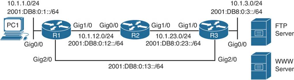
Figure 12-10 Static Routing Trouble Tickets Topology
Trouble Ticket 12-1
Problem: Users in the 10.1.1.0/24 network have indicated that they are not able to access resources on the FTP server in the 10.1.3.0/24 network. The FTP server uses a static IPv4 address of 10.1.3.10. They also indicate that they are able to access the web server at 10.1.3.5. (Note: This network only uses static routes.)
You start your troubleshooting efforts by verifying the problem with a ping to 10.1.3.10 from PC1 in the 10.1.1.0/24 network. As shown in Example 12-23 the ping is not successful. R1 is responding with a destination unreachable message. This indicates that R1 does not know how to route the packet destined for 10.1.3.10. In addition, you ping 10.1.3.5 from PC1, and it is successful, as shown in Example 12-23 as well.
Example 12-23 Failed Ping From PC1 to 10.1.3.10 and Successful Ping to 10.1.3.5
C:\PC1>ping 10.1.3.10
Pinging 10.1.3.10 with 32 bytes of data;
Reply from 10.1.1.1: Destination host unreachable.
Reply from 10.1.1.1: Destination host unreachable.
Reply from 10.1.1.1: Destination host unreachable.
Reply from 10.1.1.1: Destination host unreachable.
Ping statistics for 10.1.3.10:
Packets: Sent = 4, Received = 4, lost = 0 (0% loss),
Approximate round trip times in milli-seconds:
Minimum = 0ms, Maximum = 0ms, Average = 0ms
C:\PC1>ping 10.1.3.5
Pinging 10.1.3.5 with 32 bytes of data:
Reply from 10.1.3.5: bytes=32 time 1ms TTL=128
Reply from 10.1.3.5: bytes=32 time 1ms TTL=128
Reply from 10.1.3.5: bytes=32 time 1ms TTL=128
Reply from 10.1.3.5: bytes=32 time 1ms TTL=128
Ping statistics for 10.1.3.5:
Packets: Sent = 4, Received = 4, Lost = 0 (0% loss),
Approximate round trip times in milli-seconds:
Minimum = 0ms, Maximum = 0ms, Average = 0ms
Next you access R1 and issue the show ip route command on R1 to verify whether it knows how to route the packet to 10.1.3.10. In Example 12-24, the closest entry that would match 10.1.3.10 is the entry for 10.1.3.0/29. However, does 10.1.3.10 fall within that subnet?
Example 12-24 Verifying Routing Table Entries
R1#show ip route
...output omitted...
Gateway of last resort is not set
10.0.0.0/8 is variably subnetted, 6 subnets, 3 masks
C 10.1.1.0/24 is directly connected, GigabitEthernet0/0
L 10.1.1.1/32 is directly connected, GigabitEthernet0/0
S 10.1.3.0/29 [1/0] via 10.1.12.2
C 10.1.12.0/24 is directly connected, GigabitEthernet1/0
L 10.1.12.1/32 is directly connected, GigabitEthernet1/0
S 10.1.23.0/24 [1/0] via 10.1.12.2
The network 10.1.3.0/29 would have a range of addresses from 10.1.3.0 to 10.1.3.7. Therefore, 10.1.3.10 does not fall within that subnet, but 10.1.3.5 does. This explains why the users can reach one address and not the other in the 10.1.3.0/24 network. If you execute the show ip route 10.1.3.10 and show ip route 10.1.3.5 commands on R1, the output will verify this further. As shown in Example 12-25, there is no match for 10.1.3.10, but there is one for 10.1.3.5.
Example 12-25 Verifying Specific Routes
R1#show ip route 10.1.3.10
% Subnet not in table
R1#show ip route 10.1.3.5
Routing entry for 10.1.3.0/29
Known via "static", distance 1, metric 0
Routing Descriptor Blocks:
10.1.12.2
Route metric is 0, traffic share count is 1
Because the network in Figure 12-10 is 10.1.3.0/24, and the entry in the routing table is 10.1.3.0/29, it is possible that the static route was misconfigured. You need to verify this by examining the running configuration using the show run | include ip route command, as shown in Example 12-26. Notice the command ip route 10.1.3.0 255.255.255.248 10.1.12.2. This is the command that is producing the 10.1.3.0/29 entry in the routing table. If you look closely, you will notice that the subnet mask was not configured correctly.
Example 12-26 Examining the Static Routes on R1 in the Running Configuration
R1#show run | include ip route
ip route 10.1.3.0 255.255.255.248 10.1.12.2
ip route 10.1.23.0 255.255.255.0 10.1.12.2
To solve this issue, you need to remove the static route with the command no ip route 10.1.3.0 255.255.255.248 10.1.12.2 and create a new static route with the ip route 10.1.3.0 255.255.255.0 10.1.12.2 command.
After you do this, you issue the show ip route command on R1 and confirm that the entry in the routing table is 10.1.3.0/24, as shown in Example 12-27.
Example 12-27 Verifying Updated Static Route in the Routing Table on R1
R1#show ip route
...output omitted...
Gateway of last resort is not set
10.0.0.0/8 is variably subnetted, 6 subnets, 2 masks
C 10.1.1.0/24 is directly connected, GigabitEthernet0/0
L 10.1.1.1/32 is directly connected, GigabitEthernet0/0
S 10.1.3.0/24 [1/0] via 10.1.12.2
C 10.1.12.0/24 is directly connected, GigabitEthernet1/0
L 10.1.12.1/32 is directly connected, GigabitEthernet1/0
S 10.1.23.0/24 [1/0] via 10.1.12.2
Next you issue the show ip route 10.1.3.10 command, as shown in Example 12-28, and notice that the IP 10.1.3.10 now matches an entry in the routing table.
Example 12-28 Verifying an Entry Exists for 10.1.3.10
R1#show ip route 10.1.3.10
Routing entry for 10.1.3.0/24
Known via "static", distance 1, metric 0
Routing Descriptor Blocks:
10.1.12.2
Route metric is 0, traffic share count is 1
Finally, you ping from PC1 to the IP address 10.1.3.10, and the ping is successful, as shown in Example 12-29.
Example 12-29 Successful Ping from PC1 to 10.1.3.10
C:\PC1>ping 10.1.3.10
Pinging 10.1.3.10 with 32 bytes of data:
Reply from 10.1.3.10: bytes=32 time 1ms TTL=128
Reply from 10.1.3.10: bytes=32 time 1ms TTL=128
Reply from 10.1.3.10: bytes=32 time 1ms TTL=128
Reply from 10.1.3.10: bytes=32 time 1ms TTL=128
Ping statistics for 10.1.3.10:
Packets: Sent = 4, Received = 4, Lost = 0 (0% loss),
Approximate round trip times in milli-seconds:
Minimum = 0ms, Maximum = 0ms, Average = 0ms
Trouble Ticket 12-2
Problem: Your proactive traffic monitoring indicates that all traffic from 2001:DB8:0:1::/64 destined to 2001:DB8:0:3::/64 is going through R2 when it should be going directly to R3 over the Gig2/0 link. R2 should only be used to forward traffic from 2001:DB8:0:1::/64 to 2001:DB8:0:3::/64 if the Gig2/0 link fails, which it has not. You need to determine why traffic is being forwarded the wrong way and fix it. (Note: This network only uses static routes.)
You start by confirming the problem with a trace, as shown in Example 12-30, from PC1 to 2001:DB8:0:3::3, which is the IPv6 address of the Gig0/0 interface on R3. The trace confirms that the packets are being sent though R2.
Example 12-30 Trace from PC1 to R3s Gig0/0 Interface
C:\PC1>tracert 2001:DB8:0:3::3
Tracing route to 2001:DB8:0:3::3 over a maximum of 30 hops
1 6 ms 1 ms 2 ms 2001:DB8:0:1::1
2 5 ms 1 ms 2 ms 2001:DB8:0:12::2
3 5 ms 1 ms 2 ms 2001:DB8:0:23::3
Trace complete.
Now you issue the show ipv6 route 2001:DB8:0:3::/64 command on R1, as shown in Example 12-31, and confirm that the next-hop IPv6 address for 2001:DB8:0:3::/64 is 2001:DB8:0:12::2, which is the IPv6 address of R2s Gig0/0 interface. The next-hop IPv6 address should be 2001:DB8:0:13::3 which is R3’s Gig2/0 interface.
Example 12-31 Verifying the IPv6 Route to 2001:DB8:0:3::/64 on R1
R1#show ipv6 route 2001:DB8:0:3::/64
Routing entry for 2001:DB8:0:3::/64
Known via "static", distance 10, metric 0
Backup from "static [11]"
Route count is 1/1, share count 0
Routing paths:
2001:DB8:0:12::2
Last updated 00:09:07 ago
It appears that someone provided the incorrect next-hop IPv6 address in the static route. You verify the static route configured on R1 for the 2001:DB8:0:3::/64 network using the show run | include ipv6 route command, as shown in Example 12-32. You notice that there are two commands for the network 2001:DB8:0:3::/64. One has a next hop of 2001:DB8:0:12::2, and the other has a next hop of 2001:DB8:0:13::3.
Example 12-32 Verifying the IPv6 Static Routes Configured on R1
R1#show run | include ipv6 route
ipv6 route 2001:DB8:0:3::/64 2001:DB8:0:12::2 10
ipv6 route 2001:DB8:0:3::/64 2001:DB8:0:13::3 11
ipv6 route 2001:DB8:0:23::/64 2001:DB8:0:12::2
Why is the ipv6 route command with the next hop of 2001:DB8:0:12::2 being preferred over the command with a next hop of 2001:DB8:0:13::3? If you look closely at both commands in Example 12-32, you will notice that the one with a next hop of 2001:DB8:0:12::2 is configured with an AD of 10 and that the other, which has a next hop of 2001:DB8:0:13::3, is configured with an AD of 11. Because lower AD is preferred, the static route with the AD of 10 is more trustworthy and therefore used.
To solve this issue, you need to configure the static route with the next hop of 2001:DB8:0:13::3 with a lower AD. In this case, you change the AD to 1, which is the default for static routes, with the ipv6 route 2001:DB8:0:3::/64 2001:DB8:0:13::3 1 command. After the change, you revisit the routing table with the show ipv6 route 2001:DB8:0:3::/64 command to verify that the static route with the next hop of 2001:DB8:0:13::3 is now in the routing table. Example 12-33 confirms that the change was successful.
Example 12-33 Verifying IPv6 Routing Table on R1
R1#show ipv6 route 2001:DB8:0:3::/64
Routing entry for 2001:DB8:0:3::/64
Known via "static", distance 1, metric 0
Backup from "static [11]"
Route count is 1/1, share count 0
Routing paths:
2001:DB8:0:13::3
Last updated 00:01:14 ago
Now you perform a trace from PC1 to 2001:DB8:0:3::3, as shown in Example 12-34, and it confirms that R2 is no longer being used. The traffic is now flowing across the link between R1 and R3.
Example 12-34 Trace from PC1 to R3’s Gig0/0 Interface
C:\PC1>tracert 2001:DB8:0:3::3
Tracing route to 2001:DB8:0:3::3 over a maximum of 30 hops
1 6 ms 1 ms 2 ms 2001:DB8:0:1::1
2 5 ms 1 ms 2 ms 2001:DB8:0:13::3
Trace complete.
Troubleshooting GRE Tunnels
Generic routing encapsulation (GRE) is a tunneling protocol that is used to encapsulate various types of network layer packets inside a transport protocol (GRE) so that they can be transported over an IP network. For example, you could take IPv6 network layer packets and encapsulate them in GRE so that they can be transported over an IPv4 network. Discussions related to GRE can be extensive. However, this book is focused on getting you ready for the TSHOOT certification exam. Therefore, we focus our GRE discussion on exam preparation. As a result, this section covers the benefits of using GRE for site-to-site VPNs in addition to the issues that could cause your GRE tunnels for IPv4 and IPv6 packets not to function as expected.
With GRE, you can create virtual point-to-point links between remote Cisco routers across an IP network, as shown in Figure 12-11. HQ, which is in San Francisco, and Branch, which is in Toronto, are both connected to the Internet and are not directly connected to each other. However, by using a GRE tunnel, you can virtually directly connect the two routers. Example 12-35 provides a sample configuration that would be used on HQ to configure the GRE tunnel, and Example 12-36 provides a sample configuration that would be used on Branch to configure the GRE tunnel. The tunnel IP address is 172.16.1.1 for HQ and 172.16.1.2 for Branch. HQ is using Fa3/0 as the source of the tunnel and the IP address of 203.0.113.1 as the tunnel destination. Branch is using Fa1/0 as the source of the tunnel and the IP address of 192.0.2.1 as the tunnel destination. The tunnel mode is not listed, which means that the default tunnel mode (point-to-point GRE) is being used. For Cisco devices, the default tunnel mode is GRE/IP. If you had changed the mode and now you want to revert back to the default mode, you use the command tunnel mode gre ip in interface tunnel configuration mode.
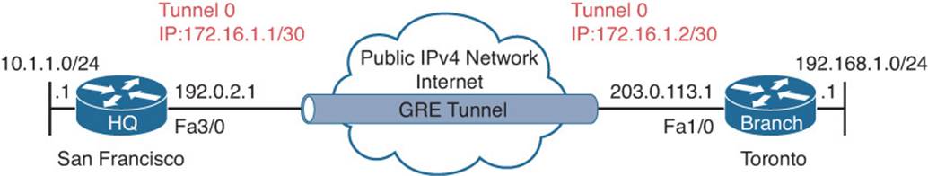
Figure 12-11 GRE Tunnel Example
Example 12-35 GRE Tunnel Configuration on HQ
HQ#show run int tunnel 0
Building configuration...
Current configuration : 127 bytes
!
interface Tunnel0
ip address 172.16.1.1 255.255.255.252
tunnel source FastEthernet3/0
tunnel destination 203.0.113.1
end
Example 12-36 GRE Tunnel Configuration on Branch
Branch#show run int tunnel 0
Building configuration...
Current configuration : 125 bytes
!
interface Tunnel0
ip address 172.16.1.2 255.255.255.252
tunnel source FastEthernet1/0
tunnel destination 192.0.2.1
end
An advantage of using GRE in this scenario is that HQ and Branch can dynamically learn about the private IPv4 networks at each site by exchanging routing information over the tunnel. Without the tunnel, this would not occur because the public IPv4 network would not allow for the exchange of such information between HQ and Branch. GRE accomplishes this by adding a GRE header (carrier protocol) to encapsulate the original packet (passenger protocol) and then adding a new IP header (transport protocol), which will be used to transport the GRE encapsulated packet over the public IPv4 network, as shown in Figure 12-12. As a result of this, users in HQ can successfully access resources in Branch (through the tunnel), and users in Branch can successfully access resources in HQ (through the tunnel), as shown in Example 12-37.
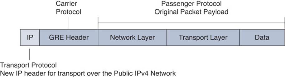
Figure 12-12 GRE Encapsulated Packet
Example 12-37 Verifying Routes via Tunnel Interface on HQ and Branch
HQ#show ip route
Codes: L - local, C - connected, S - static, R - RIP, M - mobile, B - BGP
D - EIGRP, EX - EIGRP external, O - OSPF, IA - OSPF inter area
N1 - OSPF NSSA external type 1, N2 - OSPF NSSA external type 2
E1 - OSPF external type 1, E2 - OSPF external type 2
i - IS-IS, su - IS-IS summary, L1 - IS-IS level-1, L2 - IS-IS level-2
ia - IS-IS inter area, * - candidate default, U - per-user static route
- ODR, P - periodic downloaded static route, H - NHRP, l - LISP
+ - replicated route, % - next hop override
Gateway of last resort is 192.0.2.2 to network 0.0.0.0
S* 0.0.0.0/0 [1/0] via 192.0.2.2
10.0.0.0/8 is variably subnetted, 2 subnets, 2 masks
C 10.1.1.0/24 is directly connected, GigabitEthernet0/0
L 10.1.1.1/32 is directly connected, GigabitEthernet0/0
172.16.0.0/16 is variably subnetted, 2 subnets, 2 masks
C 172.16.1.0/30 is directly connected, Tunnel0
L 172.16.1.1/32 is directly connected, Tunnel0
192.0.2.0/24 is variably subnetted, 2 subnets, 2 masks
C 192.0.2.0/30 is directly connected, FastEthernet3/0
L 192.0.2.1/32 is directly connected, FastEthernet3/0
D 192.168.1.0/24 [90/26880256] via 172.16.1.2, 00:14:08, Tunnel0
Branch#show ip route
Codes: L - local, C - connected, S - static, R - RIP, M - mobile, B - BGP
D - EIGRP, EX - EIGRP external, O - OSPF, IA - OSPF inter area
N1 - OSPF NSSA external type 1, N2 - OSPF NSSA external type 2
E1 - OSPF external type 1, E2 - OSPF external type 2
i - IS-IS, su - IS-IS summary, L1 - IS-IS level-1, L2 - IS-IS level-2
ia - IS-IS inter area, * - candidate default, U - per-user static route
- ODR, P - periodic downloaded static route, H - NHRP, l - LISP
+ - replicated route, % - next hop override
Gateway of last resort is 203.0.113.2 to network 0.0.0.0
S* 0.0.0.0/0 [1/0] via 203.0.113.2
10.0.0.0/24 is subnetted, 1 subnets
D 10.1.1.0 [90/26880256] via 172.16.1.1, 00:15:29, Tunnel0
172.16.0.0/16 is variably subnetted, 2 subnets, 2 masks
C 172.16.1.0/30 is directly connected, Tunnel0
L 172.16.1.2/32 is directly connected, Tunnel0
192.168.1.0/24 is variably subnetted, 2 subnets, 2 masks
C 192.168.1.0/24 is directly connected, GigabitEthernet0/0
L 192.168.1.1/32 is directly connected, GigabitEthernet0/0
203.0.113.0/24 is variably subnetted, 2 subnets, 2 masks
C 203.0.113.0/30 is directly connected, FastEthernet1/0
L 203.0.113.1/32 is directly connected, FastEthernet1/0
When troubleshooting GRE issues, you need to consider the following:
![]() Are the remote devices reachable across the public network? To form a GRE tunnel between the two remote devices, they must be able to reach each other’s public IP address. You can verify this using the ping command on each router, as shown in Example 12-38.
Are the remote devices reachable across the public network? To form a GRE tunnel between the two remote devices, they must be able to reach each other’s public IP address. You can verify this using the ping command on each router, as shown in Example 12-38.
![]() Are the tunnel IP addresses in the same subnet? With GRE, you are creating a virtual point-to-point connection between two remote devices; therefore, they need to be in the same subnet. You can verify the IP address on a tunnel interface, as shown in Example 12-39, using theshow interfaces tunnel tunnel_number command or the show ip interface brief command.
Are the tunnel IP addresses in the same subnet? With GRE, you are creating a virtual point-to-point connection between two remote devices; therefore, they need to be in the same subnet. You can verify the IP address on a tunnel interface, as shown in Example 12-39, using theshow interfaces tunnel tunnel_number command or the show ip interface brief command.
![]() Are the correct tunnel source and destination IP addresses specified? The tunnel needs to know where it starts and where it ends. This is based on a source IP address and a destination IP address. These addresses need to be reachable, need to be accurate, and need to be symmetrical (source on each router must match destination on other router and vise versa). You can verify the tunnel source and destination IP addresses using the show interfaces tunnel tunnel_number command, as shown in Example 12-39.
Are the correct tunnel source and destination IP addresses specified? The tunnel needs to know where it starts and where it ends. This is based on a source IP address and a destination IP address. These addresses need to be reachable, need to be accurate, and need to be symmetrical (source on each router must match destination on other router and vise versa). You can verify the tunnel source and destination IP addresses using the show interfaces tunnel tunnel_number command, as shown in Example 12-39.
![]() Is the correct tunnel mode specified? To transport IPv4 or IPv6 packets using GRE over an IPv4 network a tunnel mode of GRE IP is required. You can verify the tunnel mode used on a tunnel interface with the show interfaces tunnel tunnel_number command, as shown inExample 12-39.
Is the correct tunnel mode specified? To transport IPv4 or IPv6 packets using GRE over an IPv4 network a tunnel mode of GRE IP is required. You can verify the tunnel mode used on a tunnel interface with the show interfaces tunnel tunnel_number command, as shown inExample 12-39.
![]() Is an access control list (ACL) blocking GRE packets? GRE uses IP protocol number 47. If an ACL exists along the path between the remote devices that is denying protocol 47 or not permitting protocol 47, GRE packets will be dropped in transit. You can verify whether an ACL is applied to an interface with the show ip interface interface_type interface_number command, and you can verify the entries in an ACL with the show access-list command.
Is an access control list (ACL) blocking GRE packets? GRE uses IP protocol number 47. If an ACL exists along the path between the remote devices that is denying protocol 47 or not permitting protocol 47, GRE packets will be dropped in transit. You can verify whether an ACL is applied to an interface with the show ip interface interface_type interface_number command, and you can verify the entries in an ACL with the show access-list command.
![]() Is fragmentation occurring due to insufficient maximum transmission unit (MTU)? Because the GRE header is 24 bytes, this limits the original packet payload to 1476 bytes for a total of 1500 bytes, which equals the typical MTU of an interface. This can become an issue if large packets (original packet payload) bigger than 1476 bytes have to cross the GRE tunnel. Because the combined GRE header and original packet payload will be larger than 1500 bytes, fragmentation will occur. This results in processing delays and high CPU usage. To overcome this issue, you have to implement a consistent MTU from end to end. You can verify the MTU on a tunnel interface by using the show interface tunnel tunnel_number command, as shown in Example 12-39.
Is fragmentation occurring due to insufficient maximum transmission unit (MTU)? Because the GRE header is 24 bytes, this limits the original packet payload to 1476 bytes for a total of 1500 bytes, which equals the typical MTU of an interface. This can become an issue if large packets (original packet payload) bigger than 1476 bytes have to cross the GRE tunnel. Because the combined GRE header and original packet payload will be larger than 1500 bytes, fragmentation will occur. This results in processing delays and high CPU usage. To overcome this issue, you have to implement a consistent MTU from end to end. You can verify the MTU on a tunnel interface by using the show interface tunnel tunnel_number command, as shown in Example 12-39.
![]() Is the recursive routing table lookup pointing back to the tunnel? If you receive the syslog message %TUN-5-RECURDOWN: Tunnel0 temporarily disabled due to recursive routing, it is indicating that the router is trying to route to the tunnel destination (the public IPv4 address on the Internet in our example) using the virtual tunnel interface instead of the physical interface connected to the Internet. This can be temporary due to a flapping route elsewhere in the network, or it could be permanent due to a misconfiguration that is causing the router to route packets to the tunnel destination through the virtual tunnel interface.
Is the recursive routing table lookup pointing back to the tunnel? If you receive the syslog message %TUN-5-RECURDOWN: Tunnel0 temporarily disabled due to recursive routing, it is indicating that the router is trying to route to the tunnel destination (the public IPv4 address on the Internet in our example) using the virtual tunnel interface instead of the physical interface connected to the Internet. This can be temporary due to a flapping route elsewhere in the network, or it could be permanent due to a misconfiguration that is causing the router to route packets to the tunnel destination through the virtual tunnel interface.
![]() Is the routing protocol enabled on the tunnel interface? For routes to be shared dynamically over the tunnel, the tunnel interface needs to be participating in a routing process (for example, RIP, EIGRP, OSPF).
Is the routing protocol enabled on the tunnel interface? For routes to be shared dynamically over the tunnel, the tunnel interface needs to be participating in a routing process (for example, RIP, EIGRP, OSPF).
Example 12-38 Verifying Connectivity Between Remote Routers
HQ#ping 203.0.113.1
Type escape sequence to abort.
Sending 5, 100-byte ICMP Echos to 203.0.113.1, timeout is 2 seconds:
!!!!!
Success rate is 100 percent (5/5), round-trip min/avg/max = 36/67/104 ms
Branch#ping 192.0.2.1
Type escape sequence to abort.
Sending 5, 100-byte ICMP Echos to 192.0.2.1, timeout is 2 seconds:
!!!!!
Success rate is 100 percent (5/5), round-trip min/avg/max = 32/67/84 ms
Example 12-39 Verifying Tunnel Addresses, Mode, and MTU
HQ#show interfaces tunnel 0
Tunnel0 is up, line protocol is up
Hardware is Tunnel
Internet address is 172.16.1.1/30
MTU 17916 bytes, BW 100 Kbit/sec, DLY 50000 usec,
reliability 255/255, txload 1/255, rxload 1/255
Encapsulation TUNNEL, loopback not set
Keepalive not set
Tunnel source 192.0.2.1 (FastEthernet3/0), destination 203.0.113.1
Tunnel Subblocks:
src-track:
Tunnel0 source tracking subblock associated with FastEthernet3/0
Set of tunnels with source FastEthernet3/0, 1 member (includes iterators), on interface <OK>
Tunnel protocol/transport GRE/IP
Key disabled, sequencing disabled
Checksumming of packets disabled
Tunnel TTL 255, Fast tunneling enabled
Tunnel transport MTU 1476 bytes
Tunnel transmit bandwidth 8000 (kbps)
Tunnel receive bandwidth 8000 (kbps)
...output omitted...
HQ#show ip interface brief
Interface IP-Address OK? Method Status Protocol
Ethernet0/0 unassigned YES unset administratively down down
GigabitEthernet0/0 10.1.1.1 YES manual up up
FastEthernet3/0 192.0.2.1 YES manual up up
Tunnel0 172.16.1.1 YES manual up up
Refer to Figure 12-13; the GRE tunnel is being used to transport IPv6 packets over an IPv4 network. Examples 12-40 and 12-41 display the configurations required on HQ and Branch to accomplish this. Notice that the tunnel source and tunnel destination are IPv4 addresses and that interface Tunnel 1 is using an IPv6 address. The IPv6 address is a link-local address in this case; however, it could have been a global unicast address as well. The tunnel mode is not displayed because the default is being used. The default tunnel mode on Cisco routers is point-to-point GRE/IP.
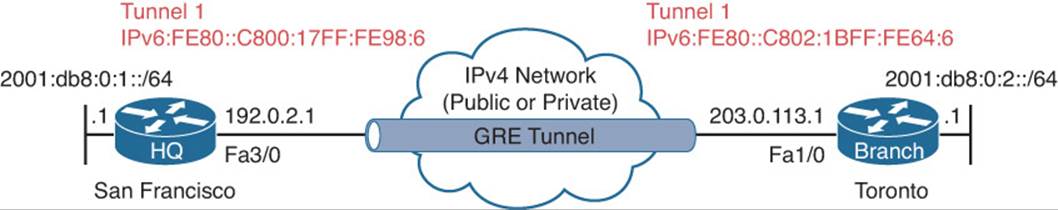
Figure 12-13 GRE Tunnel Example (for IPv6 Traffic)
Example 12-40 GRE Tunnel Configuration on HQ for IPv6
HQ#show run interface tunnel 1
Building configuration...
Current configuration : 132 bytes
!
interface Tunnel1
no ip address
ipv6 enable
ipv6 eigrp 100
tunnel source FastEthernet3/0
tunnel destination 203.0.113.1
end
Example 12-41 GRE Tunnel Configuration on Branch for IPv6
Branch#show run interface tunnel 1
Building configuration...
Current configuration : 130 bytes
!
interface Tunnel1
no ip address
ipv6 enable
ipv6 eigrp 100
tunnel source FastEthernet1/0
tunnel destination 192.0.2.1
end
The show interfaces tunnel 1 command is displayed in Example 12-42. You can see from this output that the GRE tunnel mode is GRE/IP even though you are transporting IPv6 packets over the IPv4 network. The tunnel source and destination are IPv4 addresses. The output of show ipv6 interface brief is displayed in Example 12-43 and allows you to verify the IPv6 addresses on an interface.
Example 12-42 Verifying GRE Tunnel Configuration with the show interface tunnel Command
HQ#show interface tunnel 1
Tunnel1 is up, line protocol is up
Hardware is Tunnel
MTU 17916 bytes, BW 100 Kbit/sec, DLY 50000 usec,
reliability 255/255, txload 1/255, rxload 1/255
Encapsulation TUNNEL, loopback not set
Keepalive not set
Tunnel source 192.0.2.1 (FastEthernet3/0), destination 203.0.113.1
Tunnel Subblocks:
src-track:
Tunnel1 source tracking subblock associated with FastEthernet3/0
Set of tunnels with source FastEthernet3/0, 2 members (includes iterators), on interface <OK>
Tunnel protocol/transport GRE/IP
Key disabled, sequencing disabled
Checksumming of packets disabled
Tunnel TTL 255, Fast tunneling enabled
Tunnel transport MTU 1476 bytes
Tunnel transmit bandwidth 8000 (kbps)
Tunnel receive bandwidth 8000 (kbps)
...output omitted...
Example 12-43 Verifying IPv6 Addresses of Tunnel Interface
HQ#show ipv6 interface brief
Ethernet0/0 [administratively down/down]
unassigned
GigabitEthernet0/0 [up/up]
FE80::C800:17FF:FE98:8
2001:DB8:0:1::1
FastEthernet3/0 [up/up]
unassigned
Tunnel0 [up/up]
unassigned
Tunnel1 [up/up]
FE80::C800:17FF:FE98:6
GRE is great at tunneling, but lousy at security. Its main purpose is to provide simple yet powerful tunneling for multiple network layer protocols. It provides basic plaintext authentication between the remote devices using a tunnel key, which is not a valid security solution when using GRE over an untrusted network such as the Internet.
When using GRE over an untrusted network, you want to provide confidentiality, authentication, and data integrity. You can accomplish this with IPsec. Confidentiality can be provided with symmetric algorithms, and authentication and integrity can be provided with hash message authentication codes (HMACs).
When using IPsec with GRE, GRE encapsulates the original packet payload first, and then encryption occurs next with IPsec to protect the GRE packet.
Two different IPsec modes exist that you can use to encapsulate the GRE packet (see Figure 12-14). IPsec tunnel mode will encapsulate and encrypt the entire GRE packet, including the Transport Protocol header. Because the Transport Protocol header is being encapsulated and encrypted, IPsec has to include a new IP header. IPsec transport mode will only encapsulate and encrypt the carrier protocol and the passenger protocol. Therefore, the Transport Protocol header can be reused by IPsec and reduce overhead.
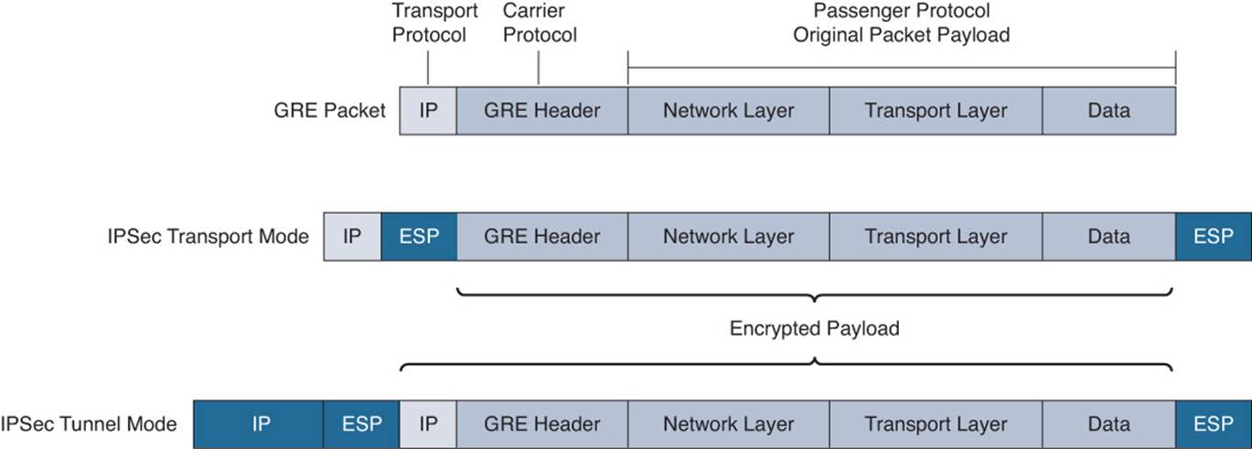
Figure 12-14 IPsec Modes
Benefits of using GRE and IPsec for site-to-site VPNs include the following:
![]() In addition to supporting IPv4 as the passenger protocol, it provides support for other Layer 3 protocols.
In addition to supporting IPv4 as the passenger protocol, it provides support for other Layer 3 protocols.
![]() It provides support for multicast and routing traffic across the IPsec VPN.
It provides support for multicast and routing traffic across the IPsec VPN.
![]() With a hub-and-spoke topology, it reduces the management overhead needed to maintain IPsec tunnels because a minimum number of tunnels is used to provide full connectivity.
With a hub-and-spoke topology, it reduces the management overhead needed to maintain IPsec tunnels because a minimum number of tunnels is used to provide full connectivity.
Exam Preparation Tasks
As mentioned in the section “How to Use This Book” in the Introduction, you have a couple of choices for exam preparation: the exercises here; Chapter 22, “Final Preparation;” and the exam simulation questions on the CD-ROM.
Review All Key Topics
Review the most important topics in this chapter, noted with the Key Topic icon in the outer margin of the page. Table 12-3 lists a reference of these key topics and the page numbers on which each is found.
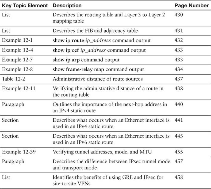
Table 12-3 Key Topics for Chapter 12
Define Key Terms
Define the following key terms from this chapter and check your answers in the glossary:
packet forwarding
ARP
TTL
routing table
ARP cache
CEF
FIB
adjacency table
control plane
data plane
administrative distance
static route
proxy ARP
GRE tunnel
Complete Tables and Lists from Memory
Print a copy of Appendix C, “Memory Tables,” (found on the disc), or at least the section for this chapter, and complete the tables and lists from memory. Appendix D, “Memory Tables Answer Key,” also on the disc, includes completed tables and lists to check your work.
Command Reference to Check Your Memory
This section includes the most important show commands covered in this chapter. It might not be necessary to memorize the complete syntax of every command, but you should be able to remember the basic keywords that are needed.
To test your memory of the commands, cover the right side of Table 12-4 with a piece of paper, read the description on the left side, and then see how much of the command you can remember.
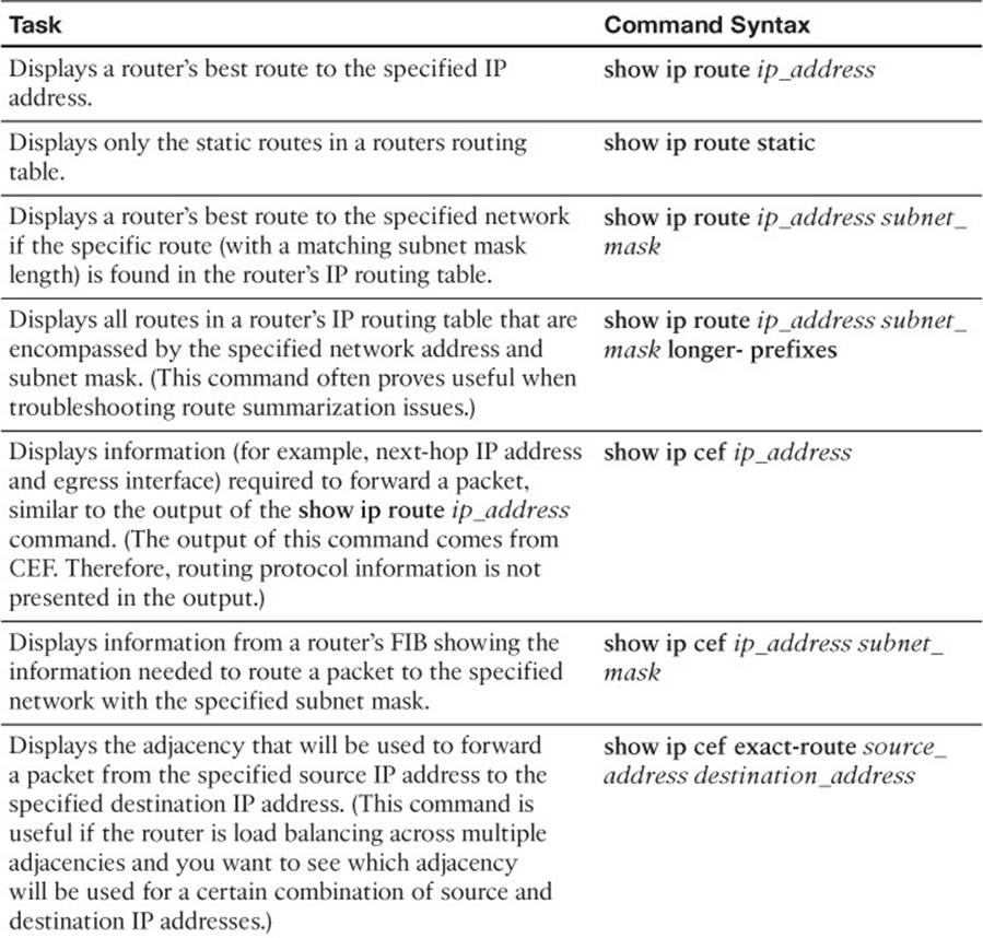
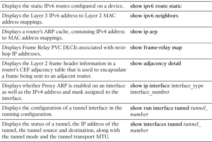
Table 12-4 show Commands
The 300-135 TSHOOT exam focuses on practical, hands-on skills that are used by a networking professional. Therefore, you should be able to identify the commands needed to verify and troubleshoot the topics covered in this chapter.
All materials on the site are licensed Creative Commons Attribution-Sharealike 3.0 Unported CC BY-SA 3.0 & GNU Free Documentation License (GFDL)
If you are the copyright holder of any material contained on our site and intend to remove it, please contact our site administrator for approval.
© 2016-2026 All site design rights belong to S.Y.A.