CCNP Routing and Switching TSHOOT 300-135 Official Cert Guide (2015)
Part III. Troubleshooting Router Features
Chapter 13. Troubleshooting RIPv2 and RIPng
This chapter covers the following topics:
![]() Troubleshooting RIPv2: This section covers the different issues that could cause routes to be missing in RIPv2 domains. You will also learn the different commands that you can use to identify and troubleshoot these issues.
Troubleshooting RIPv2: This section covers the different issues that could cause routes to be missing in RIPv2 domains. You will also learn the different commands that you can use to identify and troubleshoot these issues.
![]() Troubleshooting RIPng: This section explains the different commands that you can use to identify and troubleshoot issues related to RIPng.
Troubleshooting RIPng: This section explains the different commands that you can use to identify and troubleshoot issues related to RIPng.
![]() RIPv2 and RIPng Troubleshooting: This section provides trouble tickets that demonstrate how you can use a structured troubleshooting process to solve a reported problem.
RIPv2 and RIPng Troubleshooting: This section provides trouble tickets that demonstrate how you can use a structured troubleshooting process to solve a reported problem.
Routing Information Protocol (RIP) is one of the oldest dynamic routing protocols. It is a distance vector routing protocol that relies on hop count as the routing metric. It is not scalable like Enhanced Interior Gateway Routing Protocol (EIGRP) and Open Shortest Path First (OSPF), and it takes a considerable amount of time to fully converge after a topology change. Therefore, if used, it is used in small and simple routed networks. RIPv2 is designed for IPv4 routed networks, and RIP next generation (RIPng) is designed for IPv6 routed networks.
This chapter focuses on the issues you may have to troubleshoot in a RIPv2 and RIPng domain. This includes how you would recognize the issues based on the presented symptoms and the commands you would use to successfully verify the reason why the issue exists.
“Do I Know This Already?” Quiz
The “Do I Know This Already?” quiz allows you to assess whether you should read this entire chapter thoroughly or jump to the “Exam Preparation Tasks” section. If you are in doubt about your answers to these questions or your own assessment of your knowledge of the topics, read the entire chapter. Table 13-1 lists the major headings in this chapter and their corresponding “Do I Know This Already?” quiz questions. You can find the answers in Appendix A, “Answers to the ‘Do I Know This Already?’ Quizzes.”
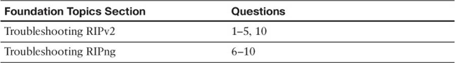
Table 13-1 “Do I Know This Already?” Section-to-Question Mapping
Caution
The goal of self-assessment is to gauge your mastery of the topics in this chapter. If you do not know the answer to a question or are only partially sure of the answer, you should mark that question as wrong for purposes of the self-assessment. Giving yourself credit for an answer that you correctly guess skews your self-assessment results and might provide you with a false sense of security.
1. Which command enables you to verify all RIPv2 routes learned from directly connected devices?
a. show ip route
b. show ip route rip
c. show ip protocols
d. show ip rip database
2. Which command enables you to verify the interfaces that are sending and receiving RIPv2 routing updates?
a. show ip route
b. show ip route rip
c. show ip protocols
d. show ip rip database
3. Which command will enable the RIPv2 routing process on the interface with an IP address of 10.1.1.7/28?
a. network 10.0.0.0
b. network 10.1.1.7 0.0.0.0
c. ip rip enable
d. ip ripv2 enable
4. What occurs when you configure a passive interface with RIPv2? (Choose two answers.)
a. The interface will send RIP updates.
b. The interface will receive RIP updates.
c. The interface will suppress the sending of RIP updates.
d. The interface will suppress the receiving of RIP updates.
5. What is the maximum hop count for RIPv2?
a. 5
b. 10
c. 15
d. 16
6. Which command enables you to verify all RIPng routes learned from directly connected devices?
a. show ipv6 rip
b. show ipv6 route rip
c. show ipv6 protocols
d. show ipv6 rip database
7. Which commands enable you to verify the interfaces that are participating in the RIPng routing process? (Choose two answers.)
a. show ipv6 rip
b. show ipv6 route rip
c. show ipv6 protocols
d. show ipv6 rip database
8. Which command enables you to verify the number of paths that will be used by RIPng for load balancing?
a. show ipv6 rip
b. show ipv6 route rip
c. show ipv6 protocols
d. show ipv6 rip database
9. Which command enables you to verify whether default routes are being generated by RIPng?
a. show ipv6 rip
b. show ipv6 route rip
c. show ipv6 protocols
d. show ipv6 rip database
10. Which of the following are reasons why a RIP route may be missing from a router running RIPv2 or RIPng? (Choose three answers.)
a. Bad or missing network statement
b. Max hop count exceeded
c. ACLs
d. Neighbor relationship not formed
Foundation Topics
Troubleshooting RIPv2
Routing Information Protocol Version 2 (RIPv2) does not establish neighbor adjacencies; therefore, you will not have to troubleshoot neighbor-related issues like you do with Enhanced Interior Gateway Routing Protocol (EIGRP), Open Shortest Path First (OSPF), and Border Gateway Protocol (BGP). However, with RIPv2, you will be troubleshooting issues related to routing updates. This section covers the reasons why a RIPv2 router may not be receiving the routes that you expect it to receive.
Missing RIPv2 Routes
A RIPv2 route may be missing from the RIP database or the routing table for many reasons. As a troubleshooter, it is important that you can recognize the reasons why routes are missing and resolve the issue quickly and efficiently.
Following is a listing of reasons as to why RIPv2 routes might be missing either in the RIP database or the routing table:

![]() Interface is shut down: The RIP-enabled interface must be up/up for the network associated with the interface to be advertised.
Interface is shut down: The RIP-enabled interface must be up/up for the network associated with the interface to be advertised.
![]() Wrong subnet: The sender of RIP updates must be in the same subnet as the receiver of RIP updates; otherwise, updates are ignored.
Wrong subnet: The sender of RIP updates must be in the same subnet as the receiver of RIP updates; otherwise, updates are ignored.
![]() Bad or missing network statement: The network command enables the RIP process on an interface and injects the network the interface is part of into the RIP process.
Bad or missing network statement: The network command enables the RIP process on an interface and injects the network the interface is part of into the RIP process.
![]() Passive interface: Suppresses the sending of RIP updates out an interface.
Passive interface: Suppresses the sending of RIP updates out an interface.
![]() Wrong version: The sender of RIP updates must be using the same RIP version as the receiver of RIP updates.
Wrong version: The sender of RIP updates must be using the same RIP version as the receiver of RIP updates.
![]() Max hop count exceeded: When the maximum hop count is exceeded, the route is unreachable and not used.
Max hop count exceeded: When the maximum hop count is exceeded, the route is unreachable and not used.
![]() Authentication: If authentication parameters do not match, routing updates are ignored.
Authentication: If authentication parameters do not match, routing updates are ignored.
![]() Route filtering: A filter might be set up that is preventing a route from being advertised or learned.
Route filtering: A filter might be set up that is preventing a route from being advertised or learned.
![]() Split horizon: Loop-prevention feature that prevents a router from advertising routes out the same interface they were learned on.
Split horizon: Loop-prevention feature that prevents a router from advertising routes out the same interface they were learned on.
![]() Autosummarization: Summarizes classless networks at classful boundaries, which is problematic in discontiguous networks.
Autosummarization: Summarizes classless networks at classful boundaries, which is problematic in discontiguous networks.
![]() Better source of information: If the exact same network is learned from a more reliable source (as determined by the administrative distance), it is used instead of the RIP-learned information.
Better source of information: If the exact same network is learned from a more reliable source (as determined by the administrative distance), it is used instead of the RIP-learned information.
![]() ACLs: If an access control list (ACL) is denying RIP packets in an interface, routes will not be learned.
ACLs: If an access control list (ACL) is denying RIP packets in an interface, routes will not be learned.
![]() Load balancing: If the maximum paths value is incorrectly set, equal metric paths for certain routes will be missing from the routing table.
Load balancing: If the maximum paths value is incorrectly set, equal metric paths for certain routes will be missing from the routing table.
To verify all routes that have been learned from neighboring routers and the directly connected routes that have been injected into the RIP process, use the show ip rip database command. This command displays the RIP database, as shown in Example 13-1. In this example, you can see two directly connected networks (10.1.1.0/24 and 10.1.12.0/24) that have been injected into the RIP process and two networks (10.1.3.0/24 and 10.1.23.0/24) that have been learned from the neighbor with an IP address of 10.1.12.2, which is also the next hop to reach those networks. The 10.1.3.0/24 network has a hop count of 2, and the 10.1.23.0/24 network has a hop count of 1. Remember that autosummarization is on by default with RIP; as a result, the router will automatically create a classful summary route, as seen with the 10.0.0.0/8 network.
Example 13-1 Viewing the RIP Database with the show ip rip database Command
R1#show ip rip database
10.0.0.0/8 auto-summary
10.1.1.0/24 directly connected, GigabitEthernet0/0
10.1.3.0/24
[2] via 10.1.12.2, 00:00:03, GigabitEthernet1/0
10.1.12.0/24 directly connected, GigabitEthernet1/0
10.1.23.0/24
[1] via 10.1.12.2, 00:00:03, GigabitEthernet1/0
To verify the RIP routes that have been installed in the routing table, use the show ip route rip command, as shown in Example 13-2. In this example, there are two RIP routes with a next-hop address of 10.1.12.2. Because they are learned via RIP, they have an administrative distance (AD) of 120 by default. The metric (hop count) for 10.1.3.0/24 is 2, as shown in the brackets, and 1 for 10.1.23.0/24.
Example 13-2 Viewing the RIP Installed Routes in the Routing Table with the show ip route rip Command
R1#show ip route rip
Codes: L - local, C - connected, S - static, R - RIP, M - mobile, B - BGP
D - EIGRP, EX - EIGRP external, O - OSPF, IA - OSPF inter area
N1 - OSPF NSSA external type 1, N2 - OSPF NSSA external type 2
E1 - OSPF external type 1, E2 - OSPF external type 2
i - IS-IS, su - IS-IS summary, L1 - IS-IS level-1, L2 - IS-IS level-2
ia - IS-IS inter area, * - candidate default, U - per-user static route
o - ODR, P - periodic downloaded static route, H - NHRP, l - LISP
+ - replicated route, % - next hop override
Gateway of last resort is not set
10.0.0.0/8 is variably subnetted, 6 subnets, 2 masks
R 10.1.3.0/24 [120/2] via 10.1.12.2, 00:00:06, GigabitEthernet1/0
R 10.1.23.0/24 [120/1] via 10.1.12.2, 00:00:06, GigabitEthernet1/0
To verify various RIP parameters and settings, use the show ip protocols command, as shown in Example 13-3. With show ip protocols, you can verify route filters that have been applied, timers, redistribution, which versions of RIP are being sent and received, the status of automatic summarization, maximum paths for load balancing, the address that was used for the network command, any passive interfaces, who the router has learned routes from, and finally, the AD. You will examine most of these as we go through examples.
Example 13-3 Viewing RIP Settings with the show ip protocols Command
R1#show ip protocols
*** IP Routing is NSF aware ***
Routing Protocol is "rip"
Outgoing update filter list for all interfaces is not set
Incoming update filter list for all interfaces is not set
Sending updates every 30 seconds, next due in 21 seconds
Invalid after 180 seconds, hold down 180, flushed after 240
Redistributing: rip
Default version control: send version 2, receive version 2
Interface Send Recv Triggered RIP Key-chain
GigabitEthernet1/0 2 2
Automatic network summarization is not in effect
Maximum path: 4
Routing for Networks:
10.0.0.0
Passive Interface(s):
Ethernet0/0
GigabitEthernet0/0
GigabitEthernet2/0
Routing Information Sources:
Gateway Distance Last Update
10.1.12.2 120 00:00:14
Distance: (default is 120)
Let’s examine each of the issues previously listed on an individual basis and identify how we can troubleshoot them.
Interface Is Shut Down
For an interface to participate in the RIP routing process, it must be up/up. You can verify the status of an interface with the show ip interface brief command, as shown in Example 13-4.
Example 13-4 Verifying the Status of an Interface
R1#show ip interface brief
Interface IP-Address OK? Method Status Protocol
Ethernet0/0 unassigned YES NVRAM administratively down down
GigabitEthernet0/0 10.1.1.1 YES NVRAM up up
GigabitEthernet1/0 10.1.12.1 YES NVRAM up up
GigabitEthernet2/0 unassigned YES NVRAM up up
Wrong Subnet
RIP routers exchanging RIP updates must be in the same subnet. If they are not, they will ignore the RIP updates that they receive from each other. See Figure 13-1, which displays a sample RIP domain where the link between R1 and R2 is not addressed properly. Notice that R1’s interface connected to R2 is in the 10.1.10.0/24 network and the interface on R2 connected to R1 is in the 10.1.12.0/24 network. When either R1 or R2 receive a RIP update from each other, they will ignore it, as shown in Example 13-5, which displays the output of debug ip rip on R1.
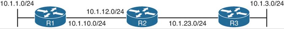
Figure 13-1 Example of Wrong Addressing Between R1 and R2
Example 13-5 Output of debug ip rip on R1
R1#debug ip rip
RIP protocol debugging is on
R1#
RIP: ignored v2 update from bad source 10.1.12.2 on GigabitEthernet1/0
As a result, both the IP address and the subnet mask assigned to an interface must be correct. In this case, the link between R1 and R2 is the 10.1.12.0/24 network. Reviewing the output of show ip interface gigabitethernet1/0 on R1 in Example 13-6 reveals that it is configured with a 10.1.10.1/24 address and mask. Therefore, it would have to be changed so that the address is 10.1.12.1/24 by using the interface command ip address 10.1.12.1 255.255.255.0.
Example 13-6 Output of show ip interface on R1
R1#show ip interface gigabitethernet1/0
GigabitEthernet1/0 is up, line protocol is up
Internet address is 10.1.10.1/24
Broadcast address is 255.255.255.255
Address determined by setup command
MTU is 1500 bytes
Helper address is not set
Directed broadcast forwarding is disabled
Multicast reserved groups joined: 224.0.0.9
...output omitted...
Bad or Missing Network Statement
The RIP process is enabled on interfaces using the classful network command in router RIP configuration mode. Once an interface is enabled for RIP, the network the interface is part of will be injected into the RIP routing process and advertised to directly connected routers out RIP-enabled interfaces. If the network command is missing, or is incorrect, the RIP process will not be enabled on the interface, and routes will be missing in the RIP domain.
To verify the interfaces enabled for RIP, use the show ip protocols command, as shown in Example 13-7. In this example, interfaces Gigabit Ethernet 0/0 and Gigabit Ethernet 1/0 are participating in the RIP routing process. In addition, you will notice the Routing for Networks: area that indicates 10.0.0.0. This is really the network command that was used to enable the RIP routing process on the interfaces. It states that the RIP routing process will be enabled on any interface that has a first octet with 10 in it. Reviewing the running configuration with the command show run | section rip, as shown in Example 13-8, confirms the network command is network 10.0.0.0. Using the command show ip interface brief, as shown in Example 13-9, indicates that Gigabit Ethernet 0/0 and Gigabit Ethernet 1/0 both have an IP address that begin with a 10 in the first octet and therefore will participate in the RIP routing process.
Example 13-7 Verifying Interfaces Participating in the RIP Process With show ip protocols
R1#show ip protocols
*** IP Routing is NSF aware ***
Routing Protocol is "rip"
Outgoing update filter list for all interfaces is not set
Incoming update filter list for all interfaces is not set
Sending updates every 30 seconds, next due in 28 seconds
Invalid after 180 seconds, hold down 180, flushed after 240
Redistributing: rip
Default version control: send version 2, receive version 2
Interface Send Recv Triggered RIP Key-chain
GigabitEthernet0/0 2 2
GigabitEthernet1/0 2 2
Automatic network summarization is not in effect
Maximum path: 4
Routing for Networks:
10.0.0.0
Routing Information Sources:
Gateway Distance Last Update
Distance: (default is 120)
Example 13-8 Verifying RIP Configurations in the Running Configuration
R1#show run | section router rip
router rip
version 2
network 10.0.0.0
no auto-summary
Example 13-9 Verifying Interface IP Addresses
R1#show ip interface brief
Interface IP-Address OK? Method Status Protocol
Ethernet0/0 unassigned YES NVRAM administratively down down
GigabitEthernet0/0 10.1.1.1 YES NVRAM up up
GigabitEthernet1/0 10.1.12.1 YES NVRAM up up
GigabitEthernet2/0 unassigned YES NVRAM up up
Passive Interface
The passive interface feature is a must have for all routing domains. It does two things: reduces the RIP related traffic on a LAN, and improves RIP security.
The passive interface feature for RIP will disable the sending of RIP updates out of the interface that is passive. Therefore, it eliminates the RIP-related traffic on the LAN leaving the router interface. This slightly improves the security of RIP because the router is not advertising RIP information out an interface that could be captured by a malicious user. However, the interface will still receive RIP updates and use them; as a result, it is possible for rogue RIP routes to be introduced into the RIP domain. Remember that when an interface is passive, the network/subnet the interface is part of will still be injected into the RIP routing process and advertised to other RIP routers.
Consider Figure 13-2, where Gigabit Ethernet 1/0 of R1 has been configured as a passive interface. In this case, R1 will not send RIP updates out Gig1/0 to R2; however, it will still receive RIP updates from R2. Therefore, R1 will know how to get to the 10.1.3.0/24 network, but R2 and R3 will not know how to reach the 10.1.1.0/24 network. Therefore, end-to-end routing is broken in this RIP domain because the passive interface feature was enabled on the wrong interface.
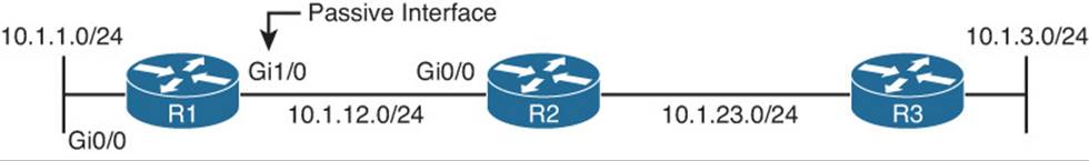
Figure 13-2 Example of Passive Interface Configured on Wrong Interface
Example 13-10 displays the output of show ip route on R1 and R2. Notice how R2 lacks the route 10.1.1.0/24 but R1 knows about 10.1.3.0/24 and 10.1.23.0/24.
Example 13-10 Verifying RIP Routes on R1 and R2
R1#show ip route
...output omitted
10.0.0.0/8 is variably subnetted, 6 subnets, 2 masks
C 10.1.1.0/24 is directly connected, GigabitEthernet0/0
L 10.1.1.1/32 is directly connected, GigabitEthernet0/0
R 10.1.3.0/24 [120/2] via 10.1.12.2, 00:00:04, GigabitEthernet1/0
C 10.1.12.0/24 is directly connected, GigabitEthernet1/0
L 10.1.12.1/32 is directly connected, GigabitEthernet1/0
R 10.1.23.0/24 [120/1] via 10.1.12.2, 00:00:04, GigabitEthernet1/0
R2#show ip route
...output omitted...
10.0.0.0/8 is variably subnetted, 5 subnets, 2 masks
R 10.1.3.0/24 [120/1] via 10.1.23.3, 00:00:04, GigabitEthernet1/0
C 10.1.12.0/24 is directly connected, GigabitEthernet0/0
L 10.1.12.2/32 is directly connected, GigabitEthernet0/0
C 10.1.23.0/24 is directly connected, GigabitEthernet1/0
L 10.1.23.2/32 is directly connected, GigabitEthernet1/0
To verify whether there are any passive interfaces configured, you use show ip protocols, as shown in Example 13-11. In this case, Gigabit Ethernet 1/0 is a passive interface when it should not be.
Example 13-11 Verifying RIP Passive Interfaces with show ip protocols
R1#show ip protocols
*** IP Routing is NSF aware ***
Routing Protocol is "rip"
Outgoing update filter list for all interfaces is not set
Incoming update filter list for all interfaces is not set
Sending updates every 30 seconds, next due in 6 seconds
Invalid after 180 seconds, hold down 180, flushed after 240
Redistributing: rip
Default version control: send version 2, receive version 2
Interface Send Recv Triggered RIP Key-chain
GigabitEthernet0/0 2 2
Automatic network summarization is not in effect
Maximum path: 4
Routing for Networks:
10.0.0.0
Passive Interface(s):
GigabitEthernet1/0
Routing Information Sources:
Gateway Distance Last Update
10.1.12.2 120 00:00:07
Distance: (default is 120)
Wrong Version
By default, RIPv1 is enabled when you start the RIP routing process with the router rip global configuration command. To enable RIPv2, you issue the version 2 command in router RIP configuration mode. If directly connected routers are not using the same version, they will not share routing information. See Figure 13-3, which shows that R1 is using RIPv1 and R2 is using RIPv2.
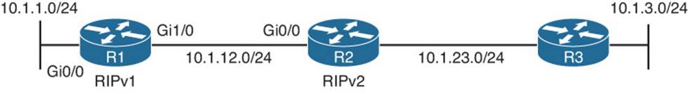
Figure 13-3 Example of Routers Using Incorrect RIP Versions
Example 13-12 displays the output of debug ip RIP on R1 and R2. Notice that they ignore the RIP routing updates from each other as they are “illegal version.” As a result, R1 in this case will not learn any RIP routes and will only have directly connected routes in the routing table. R2 will not learn any RIP routes from R1 either.
Example 13-12 Using debug ip rip to Determine Why Routes Are Not Received
R1#debug ip rip
RIP: ignored v2 packet from 10.1.12.2 (illegal version)
R1#u all
R2#debug ip rip
RIP: ignored v1 packet from 10.1.12.1 (illegal version)
R2#u all
You can verify which version of RIP is being used on a router with the show ip protocols command. As shown in Example 13-13, RIPv1 is being used for both sent updates and received updates on R1, and RIPv2 is being used for both sent and received updates on R2.
Example 13-13 Verifying the Version of RIP Being Used
R1#show ip protocols
...output omitted...
Invalid after 180 seconds, hold down 180, flushed after 240
Redistributing: rip
Default version control: send version 1, receive version 1
Interface Send Recv Triggered RIP Key-chain
GigabitEthernet0/0 1 1
GigabitEthernet1/0 1 1
Automatic network summarization is not in effect
...output omitted...
R2#show ip protocols
...output omitted...
Invalid after 180 seconds, hold down 180, flushed after 240
Redistributing: rip
Default version control: send version 2, receive version 2
Interface Send Recv Triggered RIP Key-chain
GigabitEthernet0/0 2 2
GigabitEthernet1/0 2 2
Automatic network summarization is not in effect
...output omitted...
Note that with RIP you can control on an interface-by-interface basis with the ip rip send version and ip rip receive version commands which version of RIP is used to send and receive updates, regardless of the version specified in router RIP configuration mode. Therefore, it is possible to have version 1 running but send v2 updates out an interface, or version 2 running and have v1 updates sent out an interface, as shown in Example 13-14. Notice that version 2 is running but Gigabit Ethernet 0/0 is using version 1 for sending and receiving updates, which in this case would align with R1 using version 1 and routes being exchanged successfully.
Example 13-14 Controlling RIP Version on an Interface Basis
R2#show ip protocols
*** IP Routing is NSF aware ***
Routing Protocol is "rip"
Outgoing update filter list for all interfaces is not set
Incoming update filter list for all interfaces is not set
Sending updates every 30 seconds, next due in 13 seconds
Invalid after 180 seconds, hold down 180, flushed after 240
Redistributing: rip
Default version control: send version 2, receive version 2
Interface Send Recv Triggered RIP Key-chain
GigabitEthernet0/0 1 1
GigabitEthernet1/0 2 2
Automatic network summarization is in effect
Maximum path: 4
Routing for Networks:
10.0.0.0
Routing Information Sources:
Gateway Distance Last Update
10.1.12.1 120 00:00:26
10.1.23.3 120 00:00:12
Distance: (default is 120)
Therefore, it is important to check the version being used on the router as a whole as well as the interfaces when troubleshooting RIP related issues.
Max Hop Count Exceeded
RIP has a maximum hop count of 15. Any routes that are 16 hops or further are considered unreachable. Therefore, they will not be installed in the routing table or shared with neighboring routers. Here is a listing of reasons as to why the max hop count may be exceeded:
![]() The physical topology is too large: If there are too many physical routers (15 or more) from the local router to the destination network, the hop count will be exceeded. You will need to review your network topologies and consult your documentation to verify this.
The physical topology is too large: If there are too many physical routers (15 or more) from the local router to the destination network, the hop count will be exceeded. You will need to review your network topologies and consult your documentation to verify this.
![]() The seed metric during redistribution was set to high: When routes are redistributed into RIP, you must manually set a seed metric. If you set it too high, it is possible that the route will not get advertised to the furthest RIP routers in the domain because the max hop count is reached before the routers can learn about the redistributed route. RIP redistribution is covered in a later chapter.
The seed metric during redistribution was set to high: When routes are redistributed into RIP, you must manually set a seed metric. If you set it too high, it is possible that the route will not get advertised to the furthest RIP routers in the domain because the max hop count is reached before the routers can learn about the redistributed route. RIP redistribution is covered in a later chapter.
![]() There is an offset list applied: You can use an offset list to manipulate the metric of RIP routes by adding hops before the route is advertised or once it is received. If the offset is set to high, it is possible that the route will not get advertised to the furthest RIP routers in the domain because the max hop count is reached before the routers can learn about the route.
There is an offset list applied: You can use an offset list to manipulate the metric of RIP routes by adding hops before the route is advertised or once it is received. If the offset is set to high, it is possible that the route will not get advertised to the furthest RIP routers in the domain because the max hop count is reached before the routers can learn about the route.
You can verify whether an offset list is applied using show ip protocols, as shown in Example 13-15. In this example, it states that routes received inbound on Gigabit Ethernet 1/0 that match ACL 1 will have 14 hops added to their metric. ACL 1 is shown in Example 13-16 with the show ip access-list 1 command. It matches routes that have an address of 10.1.3.0.
Example 13-15 Verifying Applied Offset Lists
R2#show ip protocols
*** IP Routing is NSF aware ***
Routing Protocol is "rip"
Outgoing update filter list for all interfaces is not set
Incoming update filter list for all interfaces is not set
Incoming routes in GigabitEthernet1/0 will have 14 added to metric if on list 1
Sending updates every 30 seconds, next due in 11 seconds
Invalid after 180 seconds, hold down 180, flushed after 240
Redistributing: rip
Default version control: send version 2, receive version 2
Interface Send Recv Triggered RIP Key-chain
GigabitEthernet0/0 2 2
GigabitEthernet1/0 2 2
Automatic network summarization is in effect
Maximum path: 4
Routing for Networks:
10.0.0.0
Routing Information Sources:
Gateway Distance Last Update
10.1.12.1 120 00:00:02
10.1.23.3 120 00:00:07
Distance: (default is 120)
Example 13-16 Verifying Access List 1 on R2
R2#show ip access-list 1
Standard IP access list 1
10 permit 10.1.3.0 (14 matches)
Reviewing the output of show ip route on R2 indicates that 10.1.3.0/24 is now 15 hops away, as shown in Example 13-17.
Example 13-17 Verifying RIP Metric for the 10.1.3.0/24 Route
R2#show ip route
...output omitted...
10.0.0.0/8 is variably subnetted, 6 subnets, 2 masks
R 10.1.1.0/24 [120/1] via 10.1.12.1, 00:00:08, GigabitEthernet0/0
R 10.1.3.0/24 [120/15] via 10.1.23.3, 00:00:28, GigabitEthernet1/0
C 10.1.12.0/24 is directly connected, GigabitEthernet0/0
L 10.1.12.2/32 is directly connected, GigabitEthernet0/0
C 10.1.23.0/24 is directly connected, GigabitEthernet1/0
L 10.1.23.2/32 is directly connected, GigabitEthernet1/0
Now take a look at the debug ip rip output on R1 in Example 13-18. Notice that when R1 receives the RIP update from R2, 10.1.3.0/24 is 16 hops away (inaccessible). Therefore, it will not be installed in R1’s routing table. Because it is not installed in R1’s routing table, it will not be advertised out any other RIP-enabled interfaces. You can verify this in the same debug output. When the RIP update is sent out Gigabit Ethernet 0/0, the 10.1.3.0/24 network is missing.
Example 13-18 Reviewing debug ip rip Output on R1
R1#debug ip rip
RIP protocol debugging is on
RIP: received v2 update from 10.1.12.2 on GigabitEthernet1/0
10.1.3.0/24 via 0.0.0.0 in 16 hops (inaccessible)
10.1.23.0/24 via 0.0.0.0 in 1 hops
R1#
RIP: sending v2 update to 224.0.0.9 via GigabitEthernet0/0 (10.1.1.1)
RIP: build update entries
10.1.12.0/24 via 0.0.0.0, metric 1, tag 0
10.1.23.0/24 via 0.0.0.0, metric 2, tag 0
Authentication
When authentication is configured on a RIP-enabled interface, it will only accept RIP updates that pass authentication, which improves security. As shown in the debug ip rip output of Example 13-19, R1 is ignoring the update from 10.1.12.2 because of invalid authentication.
Example 13-19 Ignored Update Due to Invalid Authentication
R1#debug ip rip
RIP protocol debugging is on
RIP: ignored v2 packet from 10.1.12.2 (invalid authentication)
When troubleshooting authentication, you need to consider all three of the following:
![]() Key chain configuration
Key chain configuration
![]() Key chain association
Key chain association
![]() Authentication Mode
Authentication Mode
RIP uses key chains for authentication; therefore, you need to be able to troubleshoot key chain configurations when troubleshooting RIP authentication. Example 13-20 displays the output of show key chain on R1. The key chain in this example is called RIP, it has 1 key with an ID of 1, and the key sting (text) is TSHOOT. For RIP authentication to be successful, the key ID and the key string have to match between the router interface sending the updates and the router interface receiving the updates. However, the name of the key chain does not have to match. In addition, notice the accept and send lifetime. These are used to specify when the key will be used when sending updates and when the key will be used for received updates. By default, they are always valid (never expire). However, you can modify the lifetimes to control when keys will be used. This is important if you specify multiple keys for key rotation to enhance security.
Example 13-20 Verifying Key Chain
R1#show key chain
Key-chain RIP:
key 1 -- text "TSHOOT"
accept lifetime (always valid) - (always valid) [valid now]
send lifetime (always valid) - (always valid) [valid now]
To assign a key chain to an interface using RIP, you use the ip rip authentication key-chain key_chain command in interface configuration mode. To specify the mode, you type ip rip authentication mode [text|md5]. It is imperative that neighboring RIP routers are using the same keys and the same mode. Example 13-21 displays the output of show ip protocols. You can see that Gigabit Ethernet 1/0 is configured to use the key chain named RIP. Remember that the key chain name does not have to match between the directly connected RIP routers. Therefore, once you determine the key chain applied to the interface, you would have to execute the show key chain command, as shown before in Example 13-20, to review the key ID, key string, and the validity of the keys to make sure that they match.
Example 13-21 Verifying RIP Authentication
R1#show ip protocols
*** IP Routing is NSF aware ***
Routing Protocol is "rip"
Outgoing update filter list for all interfaces is not set
Incoming update filter list for all interfaces is not set
Sending updates every 30 seconds, next due in 15 seconds
Invalid after 180 seconds, hold down 180, flushed after 240
Redistributing: rip
Default version control: send version 2, receive version 2
Interface Send Recv Triggered RIP Key-chain
GigabitEthernet1/0 2 2 RIP
Automatic network summarization is not in effect
Maximum path: 4
...output omitted...
So far, you have verified which key chain is applied and the settings of the key chain. However, you have yet to confirm the mode of authentication that is being used. RIP supports message digest 5 (MD5) authentication and simple password authentication. You are encouraged to use MD5 authentication and avoid simple password authentication in the real world. Regardless of what you use, to verify the mode you need to review the interface configuration in the running config using the show run interface interface_type interface_number command. As shown in Example 13-22, R1 is using MD5 authentication.
Example 13-22 Verifying RIP Authentication Mode
R1#show run interface gigabitethernet1/0
Building configuration...
Current configuration : 193 bytes
!
interface GigabitEthernet1/0
ip address 10.1.12.1 255.255.255.0
ip rip authentication mode md5
ip rip authentication key-chain RIP
negotiation auto
ipv6 address 2001:DB8:0:12::1/64
end
The best approach when troubleshooting authentication is to compare the authentication configurations of the two devices in question and spot the difference.
Route Filtering
A distribute list applied to the RIP process controls which routes are advertised to neighbors or which routes are received from neighbors. The distribute list is applied in RIP configuration mode either inbound or outbound, and the routes sent or received are controlled by ACLs, prefix lists, or route maps, as specified by the distribute list. So, when troubleshooting route filtering, you need to consider the following:
![]() Is the distribute list applied in the correct direction?
Is the distribute list applied in the correct direction?
![]() Is the distribute list applied to the correct interface?
Is the distribute list applied to the correct interface?
![]() If the distribute list is using an ACL, is the ACL correct?
If the distribute list is using an ACL, is the ACL correct?
![]() If the distribute list is using a prefix list, is the prefix list correct?
If the distribute list is using a prefix list, is the prefix list correct?
![]() If the distribute list is using a route map, is the route map correct?
If the distribute list is using a route map, is the route map correct?
The show ip protocols command identifies whether a distribute list is applied to all interfaces or an individual interface, as shown in Example 13-23. This example indicates that there are no outbound filters and that there is an inbound filter on Gig 1/0.
Example 13-23 Verifying Route Filters with show ip protocols
R1#show ip protocols
*** IP Routing is NSF aware ***
Routing Protocol is "rip"
Outgoing update filter list for all interfaces is not set
Incoming update filter list for all interfaces is not set
GigabitEthernet1/0 filtered by (prefix-list) TSHOOT_RIP (per-user), default is not set
Sending updates every 30 seconds, next due in 17 seconds
Invalid after 180 seconds, hold down 180, flushed after 240
Redistributing: rip
Default version control: send version 2, receive version 2
Interface Send Recv Triggered RIP Key-chain
GigabitEthernet1/0 2 2 RIP
...output omitted...
The inbound filter in Example 13-23 on Gig 1/0 is filtered by prefix list TSHOOT_RIP. To verify entries in the prefix list, you would need to issue the show ip prefix-list TSHOOT_RIP command. To verify entries in an ACL, you would need to issue the show access-lists[access_list_number | access_list_name] command. If a route map was applied, you would issue the show route-map [map_name] command.
As displayed in Example 13-24, you can verify the command that was used to apply the distribute list in the running configuration.
Example 13-24 Verifying the RIP Distribute List Command
R1#show run | section router rip
router rip
version 2
passive-interface default
no passive-interface GigabitEthernet1/0
network 10.0.0.0
distribute-list prefix TSHOOT_RIP in GigabitEthernet1/0
no auto-summary
Split Horizon
The RIP split-horizon rule states that any routes learned inbound on an interface will not be advertised out the same interface. This rule is designed to prevent routing loops. Refer to the debug ip rip output in Example 13-25, which shows how R1 only sends the 10.1.1.0/24 network to R2 and not 10.1.3.0/24, 10.1.23.0/24, or 10.1.12.0/24 as shown in Figure 13-4.
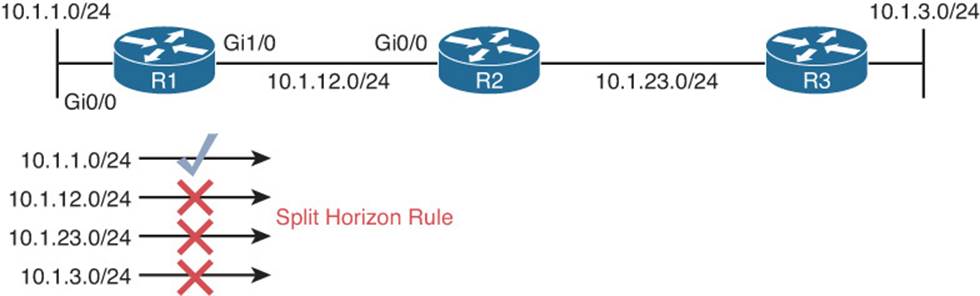
Figure 13-4 Sample Topology for Split-Horizon Rule
Example 13-25 Verifying Advertised Routes
R1#debug ip rip
RIP: sending v2 update to 224.0.0.9 via GigabitEthernet1/0 (10.1.12.1)
RIP: build update entries
10.1.1.0/24 via 0.0.0.0, metric 1, tag 0
R1#
You can verify whether split horizon is enabled on an interface with the show ip interface interface_type interface_number command, as shown in Example 13-26.
Example 13-26 Verifying That Split Horizon Is Enabled
R1#show ip interface gigabitethernet1/0
GigabitEthernet1/0 is up, line protocol is up
Internet address is 10.1.12.1/24
Broadcast address is 255.255.255.255
Address determined by setup command
MTU is 1500 bytes
Helper address is not set
Directed broadcast forwarding is disabled
Multicast reserved groups joined: 224.0.0.9
Outgoing access list is not set
Inbound access list is not set
Proxy ARP is enabled
Local Proxy ARP is disabled
Security level is default
Split horizon is enabled
ICMP redirects are always sent
ICMP unreachables are always sent
ICMP mask replies are never sent
The split-horizon rule becomes an issue in multiaccess hub-and-spoke topologies such as Frame Relay. Figure 13-5 depicts such a network. In this case, when R2 sends a RIP update about 10.1.2.0/24 to R1, R1 will not send the 10.1.2.0/24 network in its routing update out Serial 1/0 because of the split-horizon rule. Therefore, R3 never learns about 10.1.2.0/24. The same will be true about R3’s update about 10.1.3.0/24. R1 will not send 10.1.3.0/24 in the update out Serial 1/0 because of the split-horizon rule, and as a result R2 will not learn about the 10.1.3.0/24 network. You have to be able to recognize this issue based on the topology and disable the split-horizon rule for RIP on the hub routers’ multiaccess interface with the no ip split-horizon interface configuration command so that the routing updates can be sent back out the same physical interface they were received on. Your other option is to use point-to-point subinterfaces.
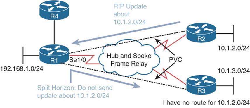
Figure 13-5 Split-Horizon in Hub-and-Spoke Multiaccess Topology
Autosummarization
RIP performs summarization automatically when it sends updates out interfaces that are part of a different classful network than the route it is advertising. This is an issue in RIP domains that have discontiguous networks. Figure 13-6 provides an example of a discontiguous network. The 172.16.0.0/16 Class B classful network is considered discontiguous because its subnets, 172.16.1.0/24 and 172.16.2.0/24, are separated from each other by another network, which is the Class A 10.0.0.0 network in this case. With automatic summarization turned on, when R3 advertises the 172.16.2.0/24 network to R2, it is summarized to 172.16.0.0/16 because it is being sent out an interface in a different network than 172.16.0.0. So, instead of 172.16.2.0/24 being sent, 172.16.0.0/16 is sent, as shown in the debug ip rip output of Example 13-27. Likewise, the same thing happens when R1 advertises the 172.16.1.0/24 network to R2; it is advertised as 172.16.0.0/16. If you were to review R2’s routing table, it would show an entry for 172.16.0.0 with two next hops (if everything else is equal), one via R3 using Fa0/1 and the other via R1 using Fa0/0.
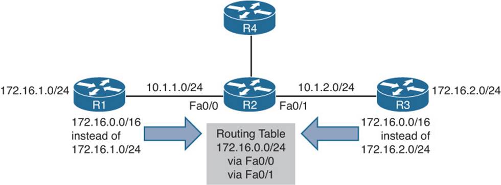
Figure 13-6 Discontiguous Network Example
Now picture a packet arriving at R2 from R4 with a destination IP of 172.16.2.5. Which way does R2 send it? You see the problem? It should send it out Fa0/1, but it could send it out Fa0/0. There is a 50/50 chance that it gets it correct. The moral of this story is this: If you have a discontiguous network, autosummarization has to be off with the no auto-summary command in router RIP configuration mode, and you must take care when performing manual summarization. To verify whether automatic summarization is enabled or disabled, use the show ip protocolscommand, as displayed in Example 13-27.
Example 13-27 Verifying Automatic Summarization
R3#debug ip rip
RIP protocol debugging is on
R3#
RIP: sending v2 update to 224.0.0.9 via FastEthernet0/1 (10.1.2.3)
RIP: build update entries
172.16.0.0/16 via 0.0.0.0, metric 1, tag 0
R3#u all
All possible debugging has been turned off
R3#show ip protocols
...output omitted...
GigabitEthernet0/0 2 2
GigabitEthernet1/0 2 2
Automatic network summarization is in effect
Maximum path: 4
Routing for Networks:
10.0.0.0
Routing Information Sources:
Gateway Distance Last Update
10.1.23.2 120 00:00:12
Distance: (default is 120)
Better Source of Information
For a RIP-learned route to be installed in the routing table, it has to be the most believable routing source. Recall that this is based on AD. RIP’s default AD is 120. Therefore, if there is another source that is educating the same router about the exact same network and that source has a better AD, the source with the better AD wins, and its information will be installed in the routing table. Review Example 13-28, which is the RIP database on R2, and Example 13-29, which is the routing table of R2 displaying only the RIP installed routes on the router. Notice that there is no entry for 10.1.3.0/24, although there should be according to Figure 13-7. Also, Example 13-30 displays the debug ip rip output on R2 that clearly shows R2 is learning it from R3.
Figure 13-7 Sample RIP topology
Example 13-28 Sample show ip rip database Command Output
R2#show ip rip database
10.0.0.0/8 auto-summary
10.1.1.0/24
[1] via 10.1.12.1, 00:00:15, GigabitEthernet0/0
10.1.12.0/24 directly connected, GigabitEthernet0/0
10.1.23.0/24 directly connected, GigabitEthernet1/0
Example 13-29 Sample show ip route rip Command Output
R2#show ip route rip
...output omitted...
10.0.0.0/8 is variably subnetted, 6 subnets, 2 masks
R 10.1.1.0/24 [120/1] via 10.1.12.1, 00:00:11, GigabitEthernet0/0
Example 13-30 Sample debug ip rip Command Output
R2#debug ip rip
RIP protocol debugging is on
R3#
RIP: received v2 update from 10.1.23.3 on GigabitEthernet1/0
10.1.3.0/24 via 0.0.0.0 in 1 hops
R3#u all
All possible debugging has been turned off
On R2, you issue the show ip route 10.1.3.0 command, as shown in Example 13-31. The output displays that the route is learned via a static route with an AD of 1. Therefore, it is more believable than the RIP-learned route from R3 and the reason why it is not in the table as a RIP learned route.
Example 13-31 Verifying the Source of 10.1.3.0 Route
R2#show ip route 10.1.3.0
Routing entry for 10.1.3.0/24
Known via "static", distance 1, metric 0
Routing Descriptor Blocks:
* 10.1.23.3
Route metric is 0, traffic share count is 1
So, what is the issue? Because 10.1.3.0 is not being used by R2 as a RIP-learned route, it will not advertise it to R1. Therefore, R1 will not know how to reach 10.1.3.0/24. Examining R1’s routing table in Example 13-32 confirms this for us.
Example 13-32 Verifying R1’s Routing Table
R2#show ip route
...output omitted...
10.0.0.0/8 is variably subnetted, 5 subnets, 2 masks
C 10.1.1.0/24 is directly connected, GigabitEthernet0/0
L 10.1.1.1/32 is directly connected, GigabitEthernet0/0
C 10.1.12.0/24 is directly connected, GigabitEthernet1/0
L 10.1.12.1/32 is directly connected, GigabitEthernet1/0
R 10.1.23.0/24 [120/1] via 10.1.12.2, 00:00:19, GigabitEthernet1/0
ACLs
RIP uses destination UDP port 520 for communication and the destination multicast address 224.0.0.9. Therefore, if there is an ACL filtering traffic in an interface and it is not permitting User Datagram Protocol (UDP) port 520 traffic or the multicast address 224.0.0.9, RIP routing updates will be denied in the interface. Example 13-33 displays access list 100 applied to interface Gigabit Ethernet 1/0 inbound. Notice that there is no entry permitting UDP port 520 traffic from R2 or all IP traffic (ip any any). Therefore, RIP packets will be denied because of the implicit deny allrule. The output of show ip route confirms that no RIP routes are learned or being used.
Example 13-33 Verifying R1’s Applied Access Lists and RIP Routes
R1#show access-list
Extended IP access list 100
10 permit ip 10.1.3.0 0.0.0.255 any
20 permit ip 10.1.23.0 0.0.0.255 any
R1#show ip interface gigabitEthernet 1/0 | include access list
Outgoing access list is not set
Inbound access list is 100
R1#show ip route rip
Codes: L - local, C - connected, S - static, R - RIP, M - mobile, B - BGP
D - EIGRP, EX - EIGRP external, O - OSPF, IA - OSPF inter area
N1 - OSPF NSSA external type 1, N2 - OSPF NSSA external type 2
E1 - OSPF external type 1, E2 - OSPF external type 2
i - IS-IS, su - IS-IS summary, L1 - IS-IS level-1, L2 - IS-IS level-2
ia - IS-IS inter area, * - candidate default, U - per-user static route
o - ODR, P - periodic downloaded static route, H - NHRP, l - LISP
+ - replicated route, % - next hop override
Gateway of last resort is not set
R1#
To solve this issue, you need to add either permit ip any any at the end of the ACL or permit udp any any eq 520 to allow the RIP packets in. However, if you want more control and security, you can specify the source address of the router you only want to receive RIPv2 packets from, which would be R2 in this case.
Load Sharing
By default, RIP will load balance on four equal metric paths. You can verify the maximum number of paths configured for load balancing with show ip protocols, as shown in Example 13-34. If you have equal metric paths but they are not being installed in the routing table for a particular destination network, check to make sure that the maximum paths is configured with an appropriate value for the number of paths you have. If it is set to 1, it means that no load balancing will occur.
Example 13-34 Verifying Maximum Paths for Load Balancing
R1#show ip protocols
*** IP Routing is NSF aware ***
Routing Protocol is "rip"
Outgoing update filter list for all interfaces is not set
Incoming update filter list for all interfaces is not set
Sending updates every 30 seconds, next due in 0 seconds
Invalid after 180 seconds, hold down 180, flushed after 240
Redistributing: rip
Default version control: send version 2, receive version 2
Interface Send Recv Triggered RIP Key-chain
GigabitEthernet1/0 2 2
Automatic network summarization is not in effect
Maximum path: 4
Routing for Networks:
10.0.0.0
Passive Interface(s):
Ethernet0/0
GigabitEthernet0/0
GigabitEthernet2/0
Routing Information Sources:
Gateway Distance Last Update
10.1.12.2 120 00:00:02
Distance: (default is 120)
Other RIP Issues
In addition to all the reasons why RIP routes might be missing, you may have to troubleshoot issues related to a missing default route or to route summarization.
Missing Default Route
There is a very small chance that a router using RIP will be able to support all 480,000+ summarized Internet routes. Therefore, redistributing the entire BGP routing table into RIP is out of the question. Therefore, for packets sourced in the RIP domain destined to the Internet to be successfully routed, the RIP routers need to know what to do with packets that they do not have a specific match for. This is where the default route enters the picture.
The default route will typically be configured on the edge device with a next-hop address of the Internet service provider’s (ISP) router (for example, ip route 0.0.0.0 0.0.0.0 203.0.13.1). However, this is a static default route on the edge router and still needs to be injected into the RIP process so that it can be advertised to the other RIP routers in the domain. To inject the default route into the RIP process, use the default-information originate command in router RIP configuration mode. (Note that with RIP you do not need the static route configured to generate a default route. If it is missing, RIP will still generate a default route and advertise it to the other routers after you enter the default-information originate command. However, if the static route is missing on the router on which you issued the command, it will not be able to forward the packets and will drop them.)
If you expect a default route on routers in the RIP domain and they are not receiving one, verify the RIP configuration on the router that should be generating the default route (typically an edge router) with the show run | section router rip command, as shown in Example 13-35. In this case, you are looking for the default-information originate command, which is configured in this example.
Example 13-35 Verifying default-information originate Configuration
Edge#show run | section router rip
show run | section router rip
router rip
version 2
passive-interface default
no passive-interface GigabitEthernet1/0
network 10.0.0.0
default-information originate
no auto-summary
You may also want to confirm the default route has been inserted into the rip database as shown in Example 13-36 with show ip rip database. Notice that it has been inserted into the RIP database and that it says redistributed.
Example 13-36 Verifying the Default Route in the RIP Database
Edge#show ip rip database
0.0.0.0/0 auto-summary
0.0.0.0/0 redistributed
[1] via 0.0.0.0,
10.0.0.0/8 auto-summary
10.1.1.0/24 directly connected, GigabitEthernet0/0
10.1.3.0/24
[2] via 10.1.12.2, 00:00:19, GigabitEthernet1/0
10.1.12.0/24 directly connected, GigabitEthernet1/0
10.1.23.0/24
[1] via 10.1.12.2, 00:00:19, GigabitEthernet1/0
Route Summarization
With RIP, manual route summarization is enabled on an interface-by-interface basis with the ip summary address rip address ip_subnet_mask interface configuration mode command. Therefore, when troubleshooting route summarization, you want to keep the following in mind:
![]() Did you enable route summarization on the correct interface?
Did you enable route summarization on the correct interface?
![]() Did you associate the summary route with RIP?
Did you associate the summary route with RIP?
![]() Did you create the appropriate summary route?
Did you create the appropriate summary route?
You can verify manual route summarization using the show ip protocols command, as shown in Example 13-37. In this example, autosummarization is disabled, and manual summarization is enabled for RIP on interface Gigabit Ethernet 1/0 for 10.1.0.0/20.
Example 13-37 Verifying Route Summarization with show ip protocols
R1#show ip protocols
*** IP Routing is NSF aware ***
Routing Protocol is "rip"
Outgoing update filter list for all interfaces is not set
Incoming update filter list for all interfaces is not set
Sending updates every 30 seconds, next due in 11 seconds
Invalid after 180 seconds, hold down 180, flushed after 240
Redistributing: rip
Default version control: send version 2, receive version 2
Interface Send Recv Triggered RIP Key-chain
GigabitEthernet1/0 2 2
Automatic network summarization is not in effect
Address Summarization:
10.1.0.0/20 for GigabitEthernet1/0
Maximum path: 4
Routing for Networks:
10.0.0.0
Passive Interface(s):
Ethernet0/0
GigabitEthernet0/0
GigabitEthernet2/0
Routing Information Sources:
Gateway Distance Last Update
Gateway Distance Last Update
10.1.12.2 120 00:00:17
Distance: (default is 120)
It is important to remember that a route to null0 is not automatically created with RIP. Therefore, if R1, as shown in Figure 13-8, is configured with a summary route, as shown previously in Example 13-37, and it has a default route in the routing table, as shown in Example 13-38, a routing loop may occur, as shown in the following paragraphs and examples.
Figure 13-8 Route Summarization Topology
Example 13-38 Verifying the Default Route on R1
R1#show ip route
...output omitted...
Gateway of last resort is 10.1.12.2 to network 0.0.0.0
R* 0.0.0.0/0 [120/2] via 10.1.12.2, 00:00:14, GigabitEthernet1/0
10.0.0.0/8 is variably subnetted, 6 subnets, 2 masks
C 10.1.1.0/24 is directly connected, GigabitEthernet0/0
L 10.1.1.1/32 is directly connected, GigabitEthernet0/0
R 10.1.3.0/24 [120/2] via 10.1.12.2, 00:00:14, GigabitEthernet1/0
C 10.1.12.0/24 is directly connected, GigabitEthernet1/0
L 10.1.12.1/32 is directly connected, GigabitEthernet1/0
R 10.1.23.0/24 [120/1] via 10.1.12.2, 00:00:14, GigabitEthernet1/0
Now suppose that R1 receives a packet destined for 10.1.5.2. What will it do with it? Based on the default route, it will send it to R2. However, in Example 13-37, you witnessed in the output of show ip protocols that a summary route for 10.1.0.0/20 was configured on R1. Using the command show ip rip database, as shown in Example 13-39, indicates 10.1.0.0/20 is installed in the RIP database. Also, reviewing the output of show ip route in Example 13-40 on R2 reveals that it is learning the summary route from R1.
Example 13-39 Verifying the Summary Route in the RIP Database
R1#show ip rip database
0.0.0.0/0 auto-summary
0.0.0.0/0
[2] via 10.1.12.2, 00:00:27, GigabitEthernet1/0
10.0.0.0/8 auto-summary
10.1.0.0/20 int-summary
10.1.1.0/24 directly connected, GigabitEthernet0/0
10.1.3.0/24
[2] via 10.1.12.2, 00:00:27, GigabitEthernet1/0
10.1.12.0/24 directly connected, GigabitEthernet1/0
10.1.23.0/24
[1] via 10.1.12.2, 00:00:27, GigabitEthernet1/0
Example 13-40 Verifying the Summary Route on R2
R2#show ip route
...output omitted...
Gateway of last resort is 10.1.23.3 to network 0.0.0.0
R* 0.0.0.0/0 [120/1] via 10.1.23.3, 00:00:20, GigabitEthernet1/0
10.0.0.0/8 is variably subnetted, 7 subnets, 3 masks
R 10.1.0.0/20 [120/1] via 10.1.12.1, 00:00:21, GigabitEthernet0/0
R 10.1.1.0/24 [120/1] via 10.1.12.1, 00:01:16, GigabitEthernet0/0
R 10.1.3.0/24 [120/1] via 10.1.23.3, 00:00:20, GigabitEthernet1/0
C 10.1.12.0/24 is directly connected, GigabitEthernet0/0
L 10.1.12.2/32 is directly connected, GigabitEthernet0/0
C 10.1.23.0/24 is directly connected, GigabitEthernet1/0
L 10.1.23.2/32 is directly connected, GigabitEthernet1/0
Because the advertised summary route includes networks that R1 truly does not know how to reach (including 10.1.5.2), a routing loop is created as packets are sent to R1, because of the summary route, and then R1 sends the packet back to R2, because of the default route. For example, R2 sends the packet destined to 10.1.5.2 back to R1, then R1 sends it back to R2, and then R2 back to R1, and so on. This is witnessed in Example 13-41 with a trace from R3 to 10.1.5.2, which loops between R2 and R1.
Example 13-41 Verifying a Routing Loop with a Trace on R3
R3#trace 10.1.5.2
Type escape sequence to abort.
Tracing the route to 10.1.5.2
VRF info: (vrf in name/id, vrf out name/id)
1 10.1.23.2 32 msec 44 msec 44 msec
2 10.1.12.1 72 msec 88 msec 84 msec
3 10.1.12.2 88 msec 92 msec 88 msec
4 10.1.12.1 152 msec 120 msec 136 msec
5 10.1.12.2 132 msec 128 msec 116 msec
6 10.1.12.1 136 msec 136 msec 124 msec
7 10.1.12.2 160 msec 136 msec *
8 10.1.12.1 156 msec 176 msec 180 msec
9 10.1.12.2 180 msec 168 msec 200 msec
10 10.1.12.1 212 msec 192 msec 196 msec
11 10.1.12.2 232 msec 196 msec 208 msec
12 10.1.12.1 244 msec 260 msec 236 msec
13 10.1.12.2 228 msec 264 msec 228 msec
14 10.1.12.1 276 msec 296 msec 288 msec
15 10.1.12.2 260 msec 276 msec 292 msec
16 10.1.12.1 292 msec 316 msec 276 msec
17 10.1.12.2 288 msec 316 msec 268 msec
18 10.1.12.1 332 msec 312 msec 368 msec
19 10.1.12.2 308 msec 336 msec 324 msec
20 10.1.12.1 364 msec 340 msec 364 msec
21 10.1.12.2 372 msec 340 msec 372 msec
22 10.1.12.1 372 msec 384 msec 372 msec
23 10.1.12.2 416 msec 384 msec 404 msec
24 10.1.12.1 428 msec 416 msec 424 msec
25 10.1.12.2 420 msec 432 msec 440 msec
26 10.1.12.1 456 msec 460 msec 452 msec
27 10.1.12.2 460 msec 484 msec 460 msec
28 10.1.12.1 468 msec 484 msec 492 msec
29 10.1.12.2 488 msec 508 msec 480 msec
30 10.1.12.1 528 msec 516 msec 548 msec
To solve this issue, you would need to create a static route to null0 on R1 for the summary route or create a better summary route. This will ensure that when R1 receives a packet that falls within the summary route but that it does not know how to reach, it will drop the packet instead of sending it back to R2 because of the default route. Example 13-42 displays the static route configuration to null0 for the same network as the summary route and the output of show ip route to verify the newly created static route.
Example 13-42 Configuring a Static Route to Null0
R1#config t
Enter configuration commands, one per line. End with CNTL/Z.
R1(config)#ip route 10.1.0.0 255.255.240.0 null 0
R1(config)#end
R1#show ip route
...output omitted...
Gateway of last resort is 10.1.12.2 to network 0.0.0.0
R* 0.0.0.0/0 [120/2] via 10.1.12.2, 00:00:01, GigabitEthernet1/0
10.0.0.0/8 is variably subnetted, 7 subnets, 3 masks
S 10.1.0.0/20 is directly connected, Null0
C 10.1.1.0/24 is directly connected, GigabitEthernet0/0
L 10.1.1.1/32 is directly connected, GigabitEthernet0/0
R 10.1.3.0/24 [120/2] via 10.1.12.2, 00:00:01, GigabitEthernet1/0
C 10.1.12.0/24 is directly connected, GigabitEthernet1/0
L 10.1.12.1/32 is directly connected, GigabitEthernet1/0
R 10.1.23.0/24 [120/1] via 10.1.12.2, 00:00:01, GigabitEthernet1/0
Example 13-43 confirms that the loop no longer exists with a trace. Notice the !H that is returned. It means the host is not reachable. In this case it is because, the packet is being dropped by the Null0 route.
Example 13-43 Confirming That the Loop No Longer Exists with a Trace
R3#trace 10.1.5.2
Type escape sequence to abort.
Tracing the route to 10.1.5.2
VRF info: (vrf in name/id, vrf out name/id)
1 10.1.23.2 32 msec 44 msec 40 msec
2 10.1.12.1 68 msec 92 msec 72 msec
3 10.1.12.1 !H !H !H
Troubleshooting RIPng
RIPng is the next generation RIP routing protocol designed for routing IPv6 addresses and prefixes. It functions the same as RIPv2, but had to be modified to support IPv6. Some of the RIPng enhancements include the use of the all-RIP-devices multicast group of FF02::9, the removal of thenetwork command, which was replaced by an interface configuration command, and the use of link-local addresses as the next-hop IPv6 address.
In this section, you will learn how to troubleshoot and verify RIPng issues.
Before you even begin troubleshooting RIPng, you need to verify that IPv6 unicast routing is enabled on the router. If it is not, it must be enabled before you proceed any further. As shown in Example 13-44, you can use the show run | include ipv6 unicast-routing command to verify if it is enabled.
Example 13-44 Confirming That IPv6 Unicast Routing Is Enabled
R1#show run | include ipv6 unicast-routing
ipv6 unicast-routing
R1#
Figure 13-9 depicts a RIPng routing domain. To verify the RIPng database on R1, you use the show ipv6 rip database command, as shown in Example 13-45. In this example, you can see that 2001:DB8:0:3::/64 and 2001:DB8:0:23::/64 are installed in the routing table but that 2001:DB8:0:12::/64 is not. This is because 2001:DB8:0:3::/64 and 2001:DB8:0:23::/64 have been learned from a neighboring router, and 2001:DB8:0:12::/64 is a directly connected network. Therefore, there is a better route based on AD that can be installed in the routing table instead of this RIPng one.
Figure 13-9 RIPng Sample Topology
Example 13-45 Sample Output of the RIPng Database
R1#show ipv6 rip database
RIP process "TSHOOT_RIP", local RIB
2001:DB8:0:3::/64, metric 3, installed
GigabitEthernet1/0/FE80::C801:3FF:FE9C:8, expires in 172 secs
2001:DB8:0:12::/64, metric 2
GigabitEthernet1/0/FE80::C801:3FF:FE9C:8, expires in 172 secs
2001:DB8:0:23::/64, metric 2, installed
GigabitEthernet1/0/FE80::C801:3FF:FE9C:8, expires in 172 secs
To verify the RIPng routes installed in the routing table, you use the show ipv6 route rip command, as shown in Example 13-46. Notice that the RIPng routes are still represented by an R and that the AD is still 120. In addition, the hop count is still based on the number of routers that have to be traversed to reach the destination network. Note that the next-hop IP address is an FE80:: link-local address.
Example 13-46 Viewing RIPng Routes in the Routing Table
R1#show ipv6 route rip
IPv6 Routing Table - default - 9 entries
Codes: C - Connected, L - Local, S - Static, U - Per-user Static route
B - BGP, R - RIP, H - NHRP, I1 - ISIS L1
I2 - ISIS L2, IA - ISIS interarea, IS - ISIS summary, D - EIGRP
EX - EIGRP external, ND - ND Default, NDp - ND Prefix, DCE - Destination
NDr - Redirect, O - OSPF Intra, OI - OSPF Inter, OE1 - OSPF ext 1
OE2 - OSPF ext 2, ON1 - OSPF NSSA ext 1, ON2 - OSPF NSSA ext 2, l - LISP
R 2001:DB8:0:3::/64 [120/3]
via FE80::C801:3FF:FE9C:8, GigabitEthernet1/0
R 2001:DB8:0:23::/64 [120/2]
via FE80::C801:3FF:FE9C:8, GigabitEthernet1/0
The show ipv6 protocols output, as shown in Example 13-47, is not as verbose as the show ip protocols output. Presently, it is only showing the interfaces that are enabled for the RIPng process called TSHOOT_RIP and that no redistribution is happening. If you want to verify timers, maximum paths, port number, multicast group, as well as the interfaces that are enabled for the RIPng process, you need to use the show ipv6 rip process_name command. In Example 13-48, the output of show ipv6 rip TSHOOT_RIP is displayed. You can verify that the maximum paths is set to 16, the multicast group is FF02::9, the RIPng port number is 521, the AD is 120, split horizon is on, updates are sent every 30 seconds and will expire after 180 seconds, and interfaces Gigabit Ethernet 0/0 and 1/0 are enabled for this RIPng process.
Example 13-47 Viewing the Output of show ipv6 protocols
R1#show ipv6 protocols
IPv6 Routing Protocol is "connected"
IPv6 Routing Protocol is "ND"
IPv6 Routing Protocol is "rip TSHOOT_RIP"
Interfaces:
GigabitEthernet1/0
GigabitEthernet0/0
Redistribution:
None
Example 13-48 Viewing the Output of show ipv6 rip TSHOOT_RIP
R1#show ipv6 rip TSHOOT_RIP
RIP process "TSHOOT_RIP", port 521, multicast-group FF02::9, pid 93
Administrative distance is 120. Maximum paths is 16
Updates every 30 seconds, expire after 180
Holddown lasts 0 seconds, garbage collect after 120
Split horizon is on; poison reverse is off
Default routes are not generated
Periodic updates 79, trigger updates 8
Full Advertisement 0, Delayed Events 0
Interfaces:
GigabitEthernet1/0
GigabitEthernet0/0
Redistribution:
None
If you want to verify the number of routes that a router is learning from a RIPng directly connected router, you can use the show ipv6 rip next-hops command, as shown in Example 13-49. In this case, we can reach three different networks (we have learned about three different networks) from the RIPng router at the next-hop IPv6 address of FE80::C801:3FF:FE9C:8.
Example 13-49 Viewing the Number of IPv6 Routes Reachable via a Next-Hop Router
R1#show ipv6 rip next-hops
RIP process "TSHOOT_RIP", Next Hops
FE80::C801:3FF:FE9C:8/GigabitEthernet1/0 [3 paths]
If you need to verify RIPng packets in real time, you can use the debug ipv6 rip command, as shown in Example 13-50. In this example, you can see the router sending RIPng updates out Gig1/0 for RIPng process TSHOOT_RIP with a link-local source address and a multicast destination of FF02::9. The prefixes are 2001:DB8:0:1::/64 and 2001:DB8:0:12::/64. The router is also receiving RIPng updates on the same interface from the device with a link-local address of FE80::C80F:1FF:FE9C:8. The routes in the update are 2001:DB8:0:12::/64, 2001:DB8:0:23::/64, and 2001:DB8:0:3::/64.
Example 13-50 Sample RIPng debug Output
R1#debug ipv6 rip
RIP Routing Protocol debugging is on
R1#
RIPng: Sending multicast update on GigabitEthernet1/0 for TSHOOT_RIP
src=FE80::C80E:1FF:FE9C:1C
dst=FF02::9 (GigabitEthernet1/0)
sport=521, dport=521, length=52
command=2, version=1, mbz=0, #rte=2
tag=0, metric=1, prefix=2001:DB8:0:1::/64
tag=0, metric=1, prefix=2001:DB8:0:12::/64
RIPng: Packet waiting
RIPng: response received from FE80::C80F:1FF:FE9C:8 on GigabitEthernet1/0 for
TSHOOT_RIP
src=FE80::C80F:1FF:FE9C:8 (GigabitEthernet1/0)
dst=FF02::9
sport=521, dport=521, length=72
command=2, version=1, mbz=0, #rte=3
tag=0, metric=1, prefix=2001:DB8:0:12::/64
tag=0, metric=1, prefix=2001:DB8:0:23::/64
tag=0, metric=2, prefix=2001:DB8:0:3::/64
R1#u all
All possible debugging has been turned off
By default, RIPng will load balance on 16 equal metric paths. You can verify the maximum number of paths configured for load balancing with the show ipv6 rip process_name command, as shown in Example 13-51. In this case, the maximum paths would have been changed to 11 with themaximum-paths command in ipv6 router rip process_name configuration mode. If you have equal metric paths but they are not being installed in the routing table for a particular destination network, check to make sure that the maximum paths is configured with an appropriate value for the number of paths you have. If it is set to 1, it means that no load balancing will occur.
Example 13-51 Verifying Maximum Paths for Load Balancing
R1#show ipv6 rip TSHOOT_RIP
RIP process "TSHOOT_RIP", port 521, multicast-group FF02::9, pid 276
Administrative distance is 120. Maximum paths is 11
Updates every 30 seconds, expire after 180
Holddown lasts 0 seconds, garbage collect after 120
Split horizon is on; poison reverse is off
Default routes are not generated
Periodic updates 71, trigger updates 2
Full Advertisement 1, Delayed Events 0
Interfaces:
GigabitEthernet1/0
GigabitEthernet0/0
Redistribution:
None
With RIPng, default routing is enabled on an interface-by-interface basis with the ipv6 rip process_name default-information [originate | only] command. The originate keyword is used to advertise a default route out the interface along with all the other routes that the router knows. Theonly keyword is used to advertise just a default route, and all other routes that would have been advertised out the interface are suppressed. You can verify whether a default route is being generated by using the show ipv6 rip process_name command, as shown in Example 13-52. However, this does not confirm what type of default route is being generated or by which interface. You must review the interface configuration in the running configuration to verify this. Using the command show run | include interface|default, as shown in Example 13-53, displays that interface Gig1/0 is configured to generate a default route and only advertise that specific route out Gig1/0.
Example 13-52 Verifying Whether a Default Route Is Being Generated
R1#show ipv6 rip TSHOOT_RIP
RIP process "TSHOOT_RIP", port 521, multicast-group FF02::9, pid 276
Administrative distance is 120. Maximum paths is 11
Updates every 30 seconds, expire after 180
Holddown lasts 0 seconds, garbage collect after 120
Split horizon is on; poison reverse is off
Default routes are generated
Periodic updates 110, trigger updates 2
Full Advertisement 1, Delayed Events 0
Interfaces:
GigabitEthernet1/0
GigabitEthernet0/0
Redistribution:
None
Example 13-53 Verifying Whether a Default Route Is Configured on an Interface
R1#show run | include interface|default
interface Ethernet0/0
interface GigabitEthernet0/0
interface GigabitEthernet1/0
ipv6 rip TSHOOT_RIP default-information only
interface GigabitEthernet2/0
ACLs can be the cause of many troubleshooting efforts. You implement an ACL on an interface to protect your network from malicious traffic only to break routing in your network because you accidentally denied the routing protocol with the implicit deny all entry in the ACL. To verify whether there are any ACLs denying packets in an interface, you can issue the debug ipv6 packets command. The debug messages will indicate that the packet is being discarded by a certain ACL. However, be very careful with this command because it debugs every single IPv6 packet and could overload the router’s processor and grind it to a halt.
An alternative is to issue the command show run | include interface|traffic to find any interface that might have the ipv6 traffic-filter command applied, as in Example 13-54. In this example, you see the IPv6 traffic filter called NETWORK is applied inbound to Gig1/0. Now you issue theshow ipv6 access-list NETWORK command to confirm whether this is in fact the reason why routes are not being learned. In Example 13-55, the only traffic that is permitted is traffic from 2001:DB8:0:3::/64 going to 2001:DB8:0:1::/64. Therefore, all other IPV6 traffic, except neighbor discovery traffic, is denied by the implicit deny all entry. Even the RIPng updates are denied. You will need to add an entry that permits UDP port 521 traffic for the RIPng updates (for example, permit udp any any eq 521).
Example 13-54 Verifying ACLs Applied to Interfaces
R1#show run | include interface|traffic
interface Ethernet0/0
interface GigabitEthernet0/0
interface GigabitEthernet1/0
ipv6 traffic-filter NETWORK in
interface GigabitEthernet2/0
Example 13-55 Verifying IPv6 ACLs
R1#show ipv6 access-list NETWORK
IPv6 access list NETWORK
permit ipv6 2001:DB8:0:3::/64 2001:DB8:0:1::/64 sequence 10
RIPng is enabled on an interface-by-interface basis with the ipv6 rip process_name enable interface configuration command. If the command is missing from the interface, the RIPng process will not be running on the interface, and the network the interface is part of will not be injected into the RIPng routing process. To verify which interfaces are participating in a particular RIPng process, you can use the show ipv6 protocols command or the show ipv6 rip process_name command, as shown in Example 13-56.
Example 13-56 Verifying RIPng-Enabled Interfaces
R1#show ipv6 protocols
IPv6 Routing Protocol is "connected"
IPv6 Routing Protocol is "ND"
IPv6 Routing Protocol is "rip TSHOOT_RIP"
Interfaces:
GigabitEthernet1/0
GigabitEthernet0/0
Redistribution:
None
R1#show ipv6 rip TSHOOT_RIP
RIP process "TSHOOT_RIP", port 521, multicast-group FF02::9, pid 93
Administrative distance is 120. Maximum paths is 16
Updates every 30 seconds, expire after 180
Holddown lasts 0 seconds, garbage collect after 120
Split horizon is on; poison reverse is off
Default routes are not generated
Periodic updates 79, trigger updates 8
Full Advertisement 0, Delayed Events 0
Interfaces:
GigabitEthernet1/0
GigabitEthernet0/0
Redistribution:
None
RIPv2 and RIPng Trouble Tickets
This section presents various trouble tickets relating to the topics discussed earlier in the chapter. The purpose of these trouble tickets is to give a process that you can follow when troubleshooting in the real world or in an exam environment. All trouble tickets in this section are based on the topology depicted in Figure 13-10.
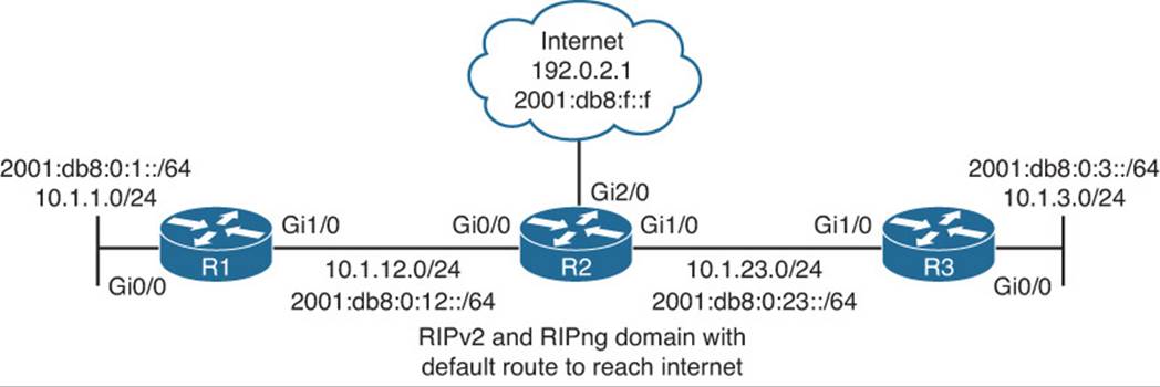
Figure 13-10 RIPv2 and RIPng Trouble Ticket Topology
Trouble Ticket 13-1
Problem: Users in the 10.1.1.0/24 network indicate that they are not able to access resources in the 10.1.3.0/24 network.
You start your troubleshooting process by confirming the issue. From a PC in the 10.1.1.0/24 network, you ping to the Gig0/0 interface on R3, which has an IP address of 10.1.3.3. In Example 13-57, the ping fails, confirming the issue. A ping to the default gateway of 10.1.1.0/24, which is 10.1.1.1, is successful, indicating that the issue is beyond the LAN and that we can start our troubleshooting efforts on R1.
Example 13-57 Confirming Issue with Ping
C:\>ping 10.1.3.3
Pinging 10.1.3.3 with 32 bytes of data:
Request timed out.
Request timed out.
Request timed out.
Request timed out.
Ping statistics for 10.1.3.3:
Packets: Sent = 4, Received = 0, Lost = 4 (100% loss),
C:\>ping 10.1.1.1
Pinging 10.1.1.1 with 32 bytes of data:
Reply from 10.1.1.1: bytes=32 time 1ms TTL=128
Reply from 10.1.1.1: bytes=32 time 1ms TTL=128
Reply from 10.1.1.1: bytes=32 time 1ms TTL=128
Reply from 10.1.1.1: bytes=32 time 1ms TTL=128
Ping statistics for 10.1.1.1:
Packets: Sent = 4, Received = 4, Lost = 0 (0% loss),
Approximate round trip times in milli-seconds:
Minimum = 0ms, Maximum = 0ms, Average = 0ms
On R1, you issue the show ip route 10.1.3.3 command. As shown in Example 13-58, the subnet is not in the table. This is a great indication that we are not learning about the 10.1.3.3 network. However, your network does use a default route; therefore, you issue the show ip route 0.0.0.0command and notice that there is a default route, as shown in Example 13-59, that points to a next hop of 10.1.12.2, which is R2. As a result, R1 should be sending the traffic to R2.
Example 13-58 Confirming Route to 10.1.3.3
R1#show ip route 10.1.3.3
% Subnet not in table
Example 13-59 Reviewing the Default Route in the Routing Table
R1#show ip route 0.0.0.0
Routing entry for 0.0.0.0/0, supernet
Known via "rip", distance 120, metric 1, candidate default path
Redistributing via rip
Last update from 10.1.12.2 on GigabitEthernet1/0, 00:00:21 ago
Routing Descriptor Blocks:
* 10.1.12.2, from 10.1.12.2, 00:00:21 ago, via GigabitEthernet1/0
Route metric is 1, traffic share count is 1
You issue a traceroute command to 10.1.3.3 on R1, sourcing it from 10.1.1.1, as shown in Example 13-60, and notice that the packet is going to the Internet at R2. It is time to shift your attention to R2.
Example 13-60 Using the traceroute Command to Verify the Path
R1#traceroute 10.1.3.3 source 10.1.1.1
Type escape sequence to abort.
Tracing the route to 10.1.3.3
VRF info: (vrf in name/id, vrf out name/id)
1 10.1.12.2 32 msec 44 msec 36 msec
2 203.0.113.2 64 msec 40 msec 60 msec
3 * * *
...output omitted...
On R2, you issue the command show ip route 10.1.3.3, and the result is the same as R1, subnet not in table, as shown in Example 13-61. It appears that R2 might not be learning about the 10.1.3.0/24 network. You issue the command show ip rip database on R2, as shown in Example 13-62, and confirm that R2 is not learning about 10.1.3.0/24 from R3.
Example 13-61 Confirming Route in R2’s Routing Table
R2#show ip route 10.1.3.3
% Subnet not in table
Example 13-62 Viewing the RIP Database on R2
R2#show ip rip database
0.0.0.0/0 auto-summary
0.0.0.0/0 redistributed
[1] via 0.0.0.0,
10.0.0.0/8 auto-summary
10.1.1.0/24
[1] via 10.1.12.1, 00:00:14, GigabitEthernet0/0
10.1.12.0/24 directly connected, GigabitEthernet0/0
10.1.23.0/24 directly connected, GigabitEthernet1/0
You hypothesize that interface Gig0/0 on R3 is not participating in the RIP process. To verify your hypothesis, you issue the show ip protocols command on R3, as shown in Example 13-63. According to the output, interface Gig0/0 is participating in the RIP process, and as a result the network associated with the interface should be advertised. You then notice that interface Gig1/0, which is connected to R2, is not participating in the RIP process, because it is not listed in the interface listing. However, you notice that it states lower in the output, Routing for Networks: 10.0.0.0. Interface Gig1/0 has an IP address of 10.1.23.3, as shown in the output of show ip interface brief of Example 13-64. Therefore, it is enabled for the RIP process and should be advertising the RIP updates to R2. You then notice that Gig1/0 is configured as a passive interface. When configured as a passive interface, the interface will still receive RIP updates but not send RIP updates. Therefore, R2 is not learning about 10.1.3.0/24, and as a result, R1 does not learn about it.
Example 13-63 Viewing the Output of show ip protocols on R3
R3#show ip protocols
*** IP Routing is NSF aware ***
Routing Protocol is "rip"
Outgoing update filter list for all interfaces is not set
Incoming update filter list for all interfaces is not set
Sending updates every 30 seconds, next due in 27 seconds
Invalid after 180 seconds, hold down 180, flushed after 240
Redistributing: rip
Default version control: send version 2, receive version 2
Interface Send Recv Triggered RIP Key-chain
GigabitEthernet0/0 2 2
Automatic network summarization is in effect
Maximum path: 4
Routing for Networks:
10.0.0.0
Passive Interface(s):
GigabitEthernet1/0
Routing Information Sources:
Gateway Distance Last Update
10.1.23.2 120 00:00:06
Distance: (default is 120)
Example 13-64 Viewing the Output of show ip interface brief on R3
R3#show ip int brief
Interface IP-Address OK? Method Status Protocol
Ethernet0/0 unassigned YES NVRAM administratively down down
GigabitEthernet0/0 10.1.3.3 YES NVRAM up up
GigabitEthernet1/0 10.1.23.3 YES NVRAM up up
You issue the command show run | section router rip and confirm that the passive-interface command is configured for interface Gig1/0, as shown in Example 13-65. You remove the command with the no passive-interface GigabitEthernet1/0 command in router RIP configuration mode.
Example 13-65 Verifying the Passive-Interface Configuration on R3
R3#show run | section router rip
router rip
version 2
passive-interface GigabitEthernet1/0
network 10.0.0.0
R3#config t
Enter configuration commands, one per line. End with CNTL/Z.
R3(config)#router rip
R3(config-router)#no passive-interface GigabitEthernet1/0
R3(config-router)#end
R3#
Now when you go back to R1 and issue the command show ip route 10.1.3.3, 10.1.3.0/24 is listed as the entry in the routing table, and the ping to 10.1.3.3 is successful, as shown in Example 13-66.
Example 13-66 Verifying 10.1.3.0/24 Route in R1’s Routing Table and a Successful Ping
R1#show ip route 10.1.3.3
Routing entry for 10.1.3.0/24
Known via "rip", distance 120, metric 2
Redistributing via rip
Last update from 10.1.12.2 on GigabitEthernet1/0, 00:00:27 ago
Routing Descriptor Blocks:
* 10.1.12.2, from 10.1.12.2, 00:00:27 ago, via GigabitEthernet1/0
Route metric is 2, traffic share count is 1
R1#ping 10.1.3.3
Type escape sequence to abort.
Sending 5, 100-byte ICMP Echos to 10.1.3.3, timeout is 2 seconds:
!!!!!
Success rate is 100 percent (5/5), round-trip min/avg/max = 36/52/64 ms
Trouble Ticket 13-2
Problem: Users in the 2001:db8:0:1::/64 network indicate that they are not able to access any resources on the Internet or the 2001:db8:0:3::/64 network.
You begin troubleshooting by verifying the problem with a ping to the Internet address of 2001:db8:f::f and the router address 2001:db8:0:3::3 with a source of 2001:db8:0:1::1. The results in Example 13-67 confirm the issues.
Example 13-67 Confirming the Users’ Issues with Pings
R1#ping 2001:db8:f::f source 2001:db8:0:1::1
Type escape sequence to abort.
Sending 5, 100-byte ICMP Echos to 2001:DB8:F::F, timeout is 2 seconds:
Packet sent with a source address of 2001:DB8:0:1::1
.....
Success rate is 0 percent (0/5)
R1#ping 2001:db8:0:3::3 source 2001:db8:0:1::1
Type escape sequence to abort.
Sending 5, 100-byte ICMP Echos to 2001:DB8:0:3::3, timeout is 2 seconds:
Packet sent with a source address of 2001:DB8:0:1::1
.....
Success rate is 0 percent (0/5)
You then issue the show ipv6 route ip_address command on R1 to determine whether a route exists. In Example 13-68, the default route is used to reach the Internet address, and 2001:DB8:0:3::/64 is used to reach 2001:DB8:0:3::3. Therefore, R1 knows how to reach the networks. In both cases, the next hop is out Gig1/0 with a link-local address of FE80::C80F:1FF:FE9C:8 (R2).
Example 13-68 Verifying Routing Table Entries for Destination Networks
R1#show ipv6 route 2001:db8:f::f
Routing entry for ::/0
Known via "rip TSHOOT_RIP", distance 120, metric 2
Route count is 1/1, share count 0
Routing paths:
FE80::C80F:1FF:FE9C:8, GigabitEthernet1/0
Last updated 01:16:36 ago
R1#show ipv6 route 2001:db8:0:3::3
Routing entry for 2001:DB8:0:3::/64
Known via "rip TSHOOT_RIP", distance 120, metric 3
Route count is 1/1, share count 0
Routing paths:
FE80::C80F:1FF:FE9C:8, GigabitEthernet1/0
Last updated 12:31:48 ago
You issue an extended IPv6 traceroute on R1 to verify the path from the 2001:db8:0:1::/64 network, and it fails immediately, as shown in Example 13-69.
Example 13-69 Issuing a Traceroute to Verify a Path
R1#traceroute ipv6
Target IPv6 address: 2001:db8:f::f
Source address: 2001:db8:0:1::1
Insert source routing header? [no]:
Numeric display? [no]:
Timeout in seconds [3]:
Probe count [3]:
Minimum Time to Live [1]:
Maximum Time to Live [30]:
Priority [0]:
Port Number [0]:
Type escape sequence to abort.
Tracing the route to 2001:DB8:F::F
1 * * *
2 * * *
3 * * *
4 * * *
5 * * *
6 * * *
7 * * *
8 * * *
9 * * *
...output omitted...
You issue a standard trace from R1 to 2001:db8:f::f so that the trace is generated with a source address of 2001:db8:0:12::1 and notice that it fails at R2, as shown in Example 13-70. However, we can see the !A, which indicates that an ACL is possibly the culprit here. This gives us something to work with now as we shift our attention to R2. However, notice that based on the source address, we had different trace results, ***, or !A !A !A.
Example 13-70 Issuing a Traceroute to Verify a Path
R1#traceroute 2001:db8:f::f
Type escape sequence to abort.
Tracing the route to 2001:DB8:F::F
1 2001:DB8:0:12::2 !A !A !A
On R2, you issue the show run | include interface|traffic-filter command to see whether any interfaces have an IPv6 ACL applied to them. The result of this command, as shown in Example 13-71, indicates that Gig0/0 (which is the interface connected to R1) has an ACL applied named TSHOOT. Your next step is to review the IPv6 ACL named TSHOOT, as shown in Example 13-72, with the show ipv6 access-list TSHOOT command. The ACL is permitting all IPv6-related traffic from 2001:DB8:0:1::/64 to anywhere. This explains why the traces produced different results. The trace is allowed when sourced from 2001:DB8:0:1::/64 but not when sourced from 2001:DB8:0:12::/64. This still does not explain why R1 has the routes to reach the networks but connectivity is failing.
Example 13-71 Verifying IPv6 ACLs Applied to Interfaces
R2#show run | include interface|traffic-filter
interface Ethernet0/0
interface GigabitEthernet0/0
ipv6 traffic-filter TSHOOT in
interface GigabitEthernet1/0
interface GigabitEthernet2/0
Example 13-72 Verifying IPv6 ACLs
R2#show ipv6 access-list TSHOOT
IPv6 access list TSHOOT
permit ipv6 2001:DB8:0:1::/64 any (74 matches) sequence 10
Let’s review R2’s routing table in Example 13-73. Maybe R2 has routes pointing to an incorrect next hop. They appear fine, so you decide to ping to make sure. As shown in the same example, they are successful.
Example 13-73 R2’s Routing Table and Successful Pings
R2#show ipv6 route
...output omitted...
S ::/0 [1/0]
via 2001:DB8:0:A::A
R 2001:DB8:0:3::/64 [120/2]
via FE80::C811:17FF:FE38:1C, GigabitEthernet1/0
C 2001:DB8:0:A::/64 [0/0]
via GigabitEthernet2/0, directly connected
...output omitted...
R2#ping 2001:db8:f::f
Type escape sequence to abort.
Sending 5, 100-byte ICMP Echos to 2001:DB8:F::F, timeout is 2 seconds:
!!!!!
Success rate is 100 percent (5/5), round-trip min/avg/max = 24/28/36 ms
R2#ping 2001:db8:0:3::3
Type escape sequence to abort.
Sending 5, 100-byte ICMP Echos to 2001:DB8:0:3::3, timeout is 2 seconds:
!!!!!
Success rate is 100 percent (5/5), round-trip min/avg/max = 8/40/88 ms
This narrows down the issue to being between R1 and R2. Recall that R1 knows about the routes. R2 knows about the routes. But, does R2 know how to reach R1 at 2001:db8:0:1::/64? You issue the command show ipv6 route 2001:db8:0:1::/64, as shown in Example 13-74, and notice that the default route is being used. Therefore, R2 does not know about 2001:db8:0:1::/64. Then you remember the ACL applied inbound on interface Gig0/0 of R2 from Example 13-72. It is permitting traffic from 2001:db8:0:1::/64 to anywhere, but it is denying everything else because of the implicit deny all rule, including RIPng updates.
Example 13-74 Verifying a Route to 2001:db8:0:1::/64 on R2
R2#show ipv6 route 2001:db8:0:1::/64
Routing entry for ::/0
Known via "static", distance 1, metric 0
Route count is 1/1, share count 0
Routing paths:
2001:DB8:0:A::A
Last updated 01:51:27 ago
To fix this issue, you need to permit RIPng updates in the ACL as well. Example 13-75 displays how this can be accomplished in addition to how it can be verified. Notice that RIPng packets are being matched to the permit statement now.
Example 13-75 Permitting UDP Port 521 Traffic in an IPv6 ACL
R2#config t
Enter configuration commands, one per line. End with CNTL/Z.
R2(config)#ipv6 access-list TSHOOT
R2(config-ipv6-acl)#permit udp any any eq 521
R2(config-ipv6-acl)#end
R2#show ipv6 access-list TSHOOT
IPv6 access list TSHOOT
permit ipv6 2001:DB8:0:1::/64 any (74 matches) sequence 10
permit udp any any eq 521 (8 matches) sequence 20
Now when you reissue the command show ipv6 route 2001:db8:0:1::/64, as shown in Example 13-76, the route is correct.
Example 13-76 Verifying Routing Table Entries
R2#show ipv6 route 2001:db8:0:1::/64
Routing entry for 2001:DB8:0:1::/64
Known via "rip TSHOOT_RIP", distance 120, metric 2
Route count is 1/1, share count 0
Routing paths:
FE80::C80E:1FF:FE9C:1C, GigabitEthernet0/0
Last updated 00:01:45 ago
Pinging from R1 to the Internet or the 2001:db8:0:3::/64 network is successful now, as shown in Example 13-77.
Example 13-77 Successful Pings
R1#ping 2001:db8:f::f source 2001:db8:0:1::1
Type escape sequence to abort.
Sending 5, 100-byte ICMP Echos to 2001:DB8:F::F, timeout is 2 seconds:
Packet sent with a source address of 2001:DB8:0:1::1
!!!!!
Success rate is 100 percent (5/5), round-trip min/avg/max = 20/33/48 ms
R1#ping 2001:db8:0:3::3 source 2001:db8:0:1::1
Type escape sequence to abort.
Sending 5, 100-byte ICMP Echos to 2001:DB8:0:3::3, timeout is 2 seconds:
Packet sent with a source address of 2001:DB8:0:1::1
!!!!!
Success rate is 100 percent (5/5), round-trip min/avg/max = 20/31/52 ms
Trouble Ticket 13-3
Problem: Users in the 2001:db8:0:1::/64 network indicate that they are not able to access resources on the Internet.
You begin troubleshooting by verifying the problem with a ping to the Internet address of 2001:db8:f::f with a source of 2001:db8:0:1::1. The results in Example 13-78 confirm the issues.
Example 13-77 Confirming the Users’ Issues with Pings
R1#ping 2001:db8:f::f source 2001:db8:0:1::1
Type escape sequence to abort.
Sending 5, 100-byte ICMP Echos to 2001:DB8:F::F, timeout is 2 seconds:
Packet sent with a source address of 2001:DB8:0:1::1
.....
Success rate is 0 percent (0/5)
You then issue the show ipv6 route ip_address command on R1 to determine whether a route exists for 2001:db8:f::f. In Example 13-78, there is no entry for that network. Based on the network topology in Figure 13-10, a default route should exist in the RIPng domain. Example 13-78 also displays the output of show ipv6 route ::/0, and the default route is not found either. On R2, you issue the same command, and Example 13-79 displays that it is known via a static route.
Example 13-78 Verifying Routing Table Entries for Destination Networks
R1#show ipv6 route 2001:db8:f::f
% Route not found
R1#show ipv6 route ::/0
% Route not found
Example 13-79 Verifying Default Route on R2
R2#show ipv6 route ::/0
Routing entry for ::/0
Known via "static", distance 1, metric 0
Route count is 1/1, share count 0
Routing paths:
2001:DB8:0:A::A
Last updated 02:49:57 ago
Next you issue the show ipv6 rip command to verify whether a default route is being generated for RIP. In Example 13-80, you can clearly see that a default route is being generated.
Example 13-80 Verifying a Default Route on R2
R2#show ipv6 rip
RIP process "TSHOOT_RIP", port 521, multicast-group FF02::9, pid 276
Administrative distance is 120. Maximum paths is 16
Updates every 30 seconds, expire after 180
Holddown lasts 0 seconds, garbage collect after 120
Split horizon is on; poison reverse is off
Default routes are generated
Periodic updates 2089, trigger updates 8
Full Advertisement 1, Delayed Events 0
Interfaces:
GigabitEthernet0/0
GigabitEthernet1/0
Redistribution:
None
But wait; remember that default routes for RIPng are configured on an interface-by-interface basis. This only tells you that a default route is being generated. It does not tell you where. Therefore, you need to issue the show run | include interface|default command, as shown in Example 13-81, to determine which RIPng interfaces are generating a default route. In this case, only Gig1/0 is. You need to add the ipv6 rip TSHOOT_RIP default-information originate command to Gig0/0 as well. Example 13-82 displays the commands needed to fix this issue.
Example 13-81 Verifying Which Interfaces Are Generating a Default Route for RIPng
R2#show run | include interface|default
interface Ethernet0/0
interface GigabitEthernet0/0
interface GigabitEthernet1/0
ipv6 rip TSHOOT_RIP default-information originate
interface GigabitEthernet2/0
Example 13-82 Configuring a RIPng Interface to Generate a Default Route
R2#config t
Enter configuration commands, one per line. End with CNTL/Z.
R2(config)#interface gigabitEthernet 0/0
R2(config-if)#ipv6 rip TSHOOT_RIP default-information originate
R2(config-if)#end
R2#
Back on R1, you issue the show ipv6 route ::/0 command again and confirm that there is an entry in the routing table. You also issue a ping to the Internet address 2001:db8:f::f, which is successful. Example 13-83 displays the routing table and the successful ping.
Example 13-83 Verifying the Issue is Solved
R1#show ipv6 route ::/0
Routing entry for ::/0
Known via "rip TSHOOT_RIP", distance 120, metric 2
Route count is 1/1, share count 0
Routing paths:
FE80::C80F:1FF:FE9C:8, GigabitEthernet1/0
Last updated 00:03:51 ago
R1#ping 2001:db8:f::f source 2001:db8:0:1::1
Type escape sequence to abort.
Sending 5, 100-byte ICMP Echos to 2001:DB8:F::F, timeout is 2 seconds:
Packet sent with a source address of 2001:DB8:0:1::1
!!!!!
Success rate is 100 percent (5/5), round-trip min/avg/max = 12/28/44 ms
R1#
Exam Preparation Tasks
As mentioned in the section “How to Use This Book” in the Introduction, you have a couple of choices for exam preparation: the exercises here; Chapter 22, “Final Preparation;” and the exam simulation questions on the CD-ROM.
Review All Key Topics
Review the most important topics in this chapter, noted with the Key Topic icon in the outer margin of the page. Table 13-2 lists a reference of these key topics and the page numbers on which each is found.
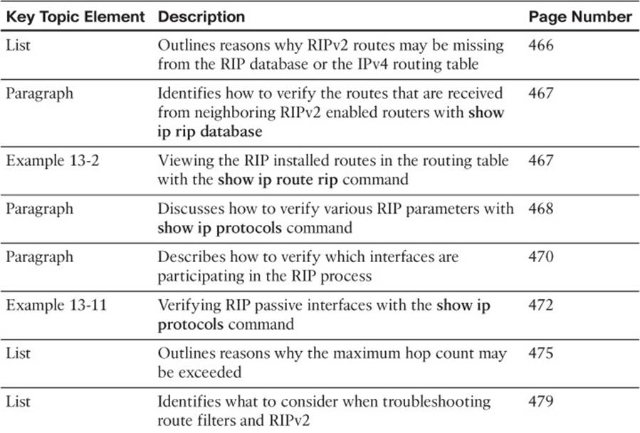
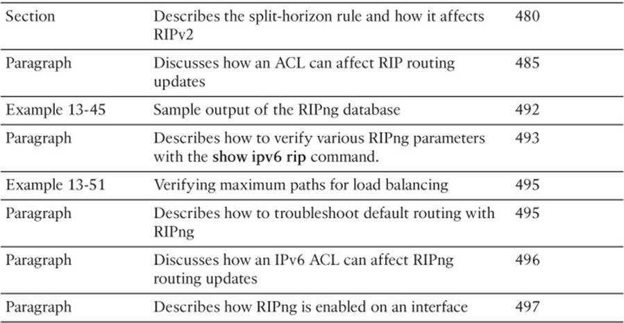
Table 13-2 Key Topics for Chapter 13
Define Key Terms
Define the following key terms from this chapter and check your answers in the glossary:
RIPv2
RIPng
network command
passive interface
hop count
split horizon
autosummarization
maximum paths
Command Reference to Check Your Memory
This section includes the most important show and debug commands covered in this chapter. It might not be necessary to memorize the complete syntax of every command, but you should be able to remember the basic keywords that are needed.
To test your memory of the commands, cover the right side of Table 13-3 with a piece of paper, read the description on the left side, and then see how much of the command you can remember.
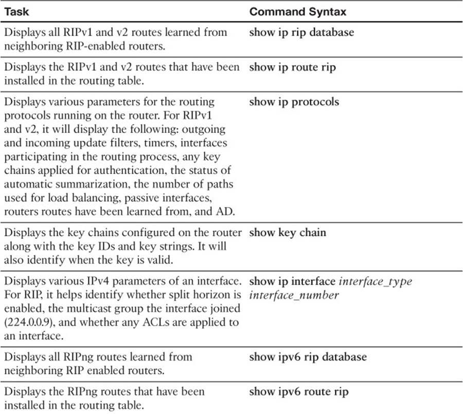
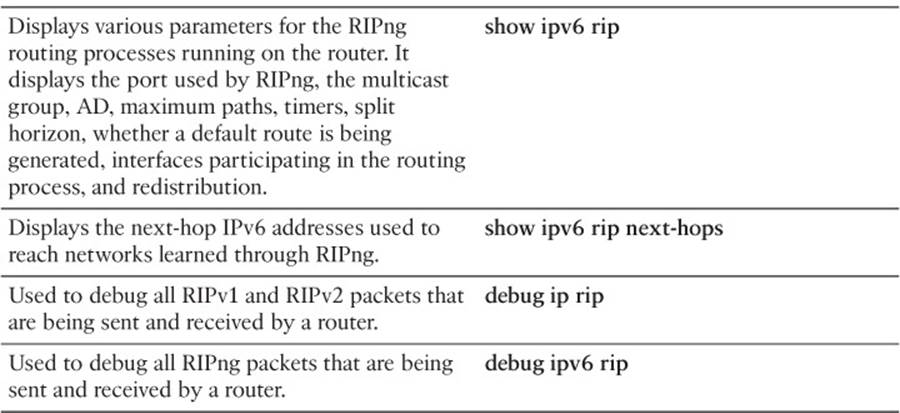
Table 13-3 show and debug commands
The 300-135 TSHOOT exam focuses on practical, hands-on skills that are used by a networking professional. Therefore, you should be able to identify the commands needed to successfully troubleshoot the topics and concepts covered in this chapter.
All materials on the site are licensed Creative Commons Attribution-Sharealike 3.0 Unported CC BY-SA 3.0 & GNU Free Documentation License (GFDL)
If you are the copyright holder of any material contained on our site and intend to remove it, please contact our site administrator for approval.
© 2016-2026 All site design rights belong to S.Y.A.