CCNP Routing and Switching TSHOOT 300-135 Official Cert Guide (2015)
Part III. Troubleshooting Router Features
Chapter 14. Troubleshooting EIGRP
This chapter covers the following topics:
![]() Troubleshooting EIGRP for IPv4: This section covers the reasons why EIGRP for IPv4 neighbor relationships are not being formed and how you can identify them. In addition, you will explore the reasons why EIGRP for IPv4 routes might be missing and how to determine why they are missing.
Troubleshooting EIGRP for IPv4: This section covers the reasons why EIGRP for IPv4 neighbor relationships are not being formed and how you can identify them. In addition, you will explore the reasons why EIGRP for IPv4 routes might be missing and how to determine why they are missing.
![]() EIGRP for IPv4 Trouble Tickets: This section provides trouble tickets that demonstrate how you can use a structured troubleshooting process to solve a reported problem.
EIGRP for IPv4 Trouble Tickets: This section provides trouble tickets that demonstrate how you can use a structured troubleshooting process to solve a reported problem.
![]() Troubleshooting EIGRP for IPv6: This section covers the reasons why EIGRP for IPv6 neighbor relationships are not being formed and how you can identify them. In addition, you will explore the reasons why EIGRP for IPv6 routes might be missing and how to determine why they are missing.
Troubleshooting EIGRP for IPv6: This section covers the reasons why EIGRP for IPv6 neighbor relationships are not being formed and how you can identify them. In addition, you will explore the reasons why EIGRP for IPv6 routes might be missing and how to determine why they are missing.
![]() EIGRP for IPv6 Trouble Tickets: This section provides trouble tickets that demonstrate how you can use a structured troubleshooting process to solve a reported problem.
EIGRP for IPv6 Trouble Tickets: This section provides trouble tickets that demonstrate how you can use a structured troubleshooting process to solve a reported problem.
![]() Troubleshooting Named EIGRP Configurations: In this section you discover the new show commands that you can use to troubleshoot named EIGRP configurations.
Troubleshooting Named EIGRP Configurations: In this section you discover the new show commands that you can use to troubleshoot named EIGRP configurations.
![]() Named EIGRP Trouble Tickets: This section provides trouble tickets that demonstrate how you can use a structured troubleshooting process to solve a reported problem.
Named EIGRP Trouble Tickets: This section provides trouble tickets that demonstrate how you can use a structured troubleshooting process to solve a reported problem.
The Cisco Enhanced Interior Gateway Routing Protocol (EIGRP) is considered an advanced distance vector routing protocol. Specifically, EIGRP advertises routes to directly attached neighbors, like a distance vector routing protocol, while forming neighbor relationships, similar to a link-state routing protocol.
EIGRP can route for both IPv4 and IPv6 protocols. This chapter focuses on troubleshooting both of these protocols using the classic configurations and the newer named EIGRP configurations.
Before any routes can be exchanged between EIGRP routers on the same LAN or across a WAN, an EIGRP neighbor relationship has to be formed. There are many reasons why a neighbor relationship will not form, and as a troubleshooter, you need to be aware of them. This chapter dives deep into these issues and gives you the tools needed to identify them and successfully solve neighbor issues.
Once neighbor relationships are formed, neighboring routers exchange EIGRP routes. In various cases, routes may end up missing, and you need to be able to determine why the routes are missing. This chapter discusses the various ways that routes could go missing and how you can identify them and solve any route-related issue.
In this chapter, you also learn how to troubleshoot issues related to load balancing, summarization, discontiguous networks, and feasible successors.
“Do I Know This Already?” Quiz
The “Do I Know This Already?” quiz allows you to assess whether you should read this entire chapter thoroughly or jump to the “Exam Preparation Tasks” section. If you are in doubt about your answers to these questions or your own assessment of your knowledge of the topics, read the entire chapter. Table 14-1 lists the major headings in this chapter and their corresponding “Do I Know This Already?” quiz questions. You can find the answers in Appendix A, “Answers to the ‘Do I Know This Already?’ Quizzes.”
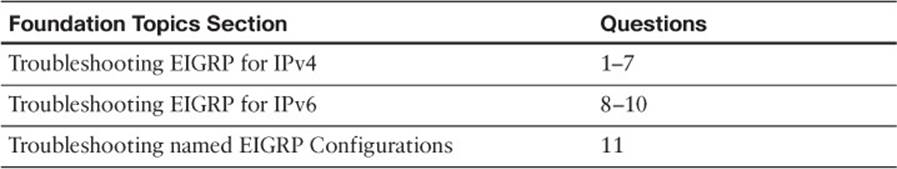
Table 14-1 “Do I Know This Already?” Section-to-Question Mapping
Caution
The goal of self-assessment is to gauge your mastery of the topics in this chapter. If you do not know the answer to a question or are only partially sure of the answer, you should mark that question as wrong for purposes of the self-assessment. Giving yourself credit for an answer that you correctly guess skews your self-assessment results and might provide you with a false sense of security.
1. Which command enables you to verify the routers that have formed an EIGRP adjacency with the local router, how long they have been neighbors for, and the current sequence number of EIGRP packets?
a. show ip eigrp interfaces
b. show ip eigrp neighbors
c. show ip route eigrp
d. show ip protocols
2. Which three of the following are reasons EIGRP neighbor relationships might not form?
a. Different autonomous system numbers
b. Different K values
c. Different timers
d. Different authentication parameters
3. Which command enables you to verify the configured EIGRP K values?
a. show ip protocols
b. show ip eigrp interfaces
c. show ip eigrp neighbor
d. show ip eigrp topology
4. Which command enables you to verify EIGRP authentication, split-horizon, and configured EIGRP timers?
a. show ip interfaces
b. show ip protocols
c. show ip eigrp interfaces detail
d. show ip eigrp neighbor
5. Besides a neighbor relationship not being formed, which three of the following are reasons why routes might be missing in your EIGRP autonomous system?
a. Interface not participating in the EIGRP process
b. Filters
c. Incorrect stub configuration
d. Passive interface feature
6. Which command enables you to verify whether any route filters have been applied to an EIGRP enabled interface?
a. show ip interface brief
b. show ip interface
c. show ip protocols
d. show ip eigrp interface
7. Which command enables you to verify the maximum paths configured for load balancing and whether unequal path load balancing has been enabled?
a. show ip protocols
b. show ip eigrp interfaces
c. show ip eigrp neighbors
d. show ip interfaces
8. Which EIGRP for IPv6 command is used to verify whether any interfaces have been configured as passive interfaces?
a. show ipv6 protocols
b. show ipv6 eigrp interface detail
c. show ipv6 eigrp neighbor detail
d. show ipv6 eigrp topology
9. Which EIGRP for IPv6 command enables you to verify whether the local router is a stub router?
a. show ipv6 protocols
b. show ipv6 eigrp interface detail
c. show ipv6 eigrp neighbor detail
d. show ipv6 eigrp topology
10. Which EIGRP for IPv6 command enables you to verify whether a neighboring router is a stub router?
a. show ipv6 protocols
b. show ipv6 eigrp interface detail
c. show ipv6 eigrp neighbor detail
d. show ipv6 eigrp topology
11. What are two ways that you can verify which interfaces are participating in the named EIGRP IPv4 address family?
a. show ip eigrp interfaces
b. show eigrp address-family ipv4 interfaces
c. show ipv6 eigrp interfaces
d. show eigrp address-family ipv6 interfaces
Foundation Topics
Troubleshooting EIGRP for IPv4
EIGRP establishes neighbor relationships by sending hello packets to the multicast address 224.0.0.10 out interfaces participating in the EIGRP process. To enable the EIGRP process on an interface, you use the network ip_address wildcard_mask command in router EIGRP configuration mode. For example, the following network command enables EIGRP on all interfaces with an IP address from 10.1.1.0 through 10.1.1.255: network 10.1.1.0 0.0.0.255. The following network command enables the EIGRP process on only the interface with the IP address 10.1.1.65:network 10.1.1.65 0.0.0.0. It seems rather simple, and it is; however, there are many reasons why a neighbor relationship may not form, and you need to be aware of all of them if you plan on successfully troubleshooting EIGRP-related problems.
After establishing a neighbor relationship, an EIGRP router performs a full exchange of routing information with the newly established neighbor. After the full exchange, only updates to route information are exchanged with that neighbor. Routing information learned from EIGRP neighbors is inserted into the EIGRP topology table. If the EIGRP information for a specific route happens to be the best source of information, it is installed in the routing table. There are various reasons as to why EIGRP routes might be missing from either the topology table or the routing table, and you need to be aware of all of them if you plan on successfully troubleshooting EIGRP route-related problems.
This section focuses on the reasons why an EIGRP neighbor relationship might not form and how you can identify them during the troubleshooting process. In addition, we examine the reasons why EIGRP routes might be missing, and how we can determine the reason why they are missing. To wrap up the section, we troubleshoot EIGRP issues that do not fall into the neighbor relationship or route categories.
Troubleshooting EIGRP for IPv4 Neighbor Adjacencies
To verify EIGRP neighbors, you use the show ip eigrp neighbors command. In Example 14-1, you can see sample output of the show ip eigrp neighbors command. It lists the IPv4 address of the neighboring device’s interface that sent the hello packet, the local interface on the router used to reach that neighbor, how long the local router will consider the neighboring router to be a neighbor, how long the routers have been neighbors for, the amount of time it takes for the neighbors to communicate on average, the number of EIGRP packets in a queue waiting to be sent to a neighbor (which should always be zero since we want up-to-date routing information), and a sequence number to keep track of the EIGRP packets received from the neighbor to ensure that only newer packets are accepted and processed.
Example 14-1 Verifying EIGRP Neighbors with show ip eigrp neighbors
R2#show ip eigrp neighbors
EIGRP-IPv4 Neighbors for AS(100)
H Address Interface Hold Uptime SRTT RTO Q Seq
(sec) (ms) Cnt Num
1 10.1.23.3 Gi1/0 14 10:01:09 72 432 0 3
0 10.1.12.1 Gi0/0 11 10:32:14 75 450 0 8
Here is a listing of reasons why an EIGRP neighbor relationship might not form:

![]() Interface is down: The interface has to be up/up.
Interface is down: The interface has to be up/up.
![]() Mismatched autonomous system numbers: Both routers need to be in the same autonomous system.
Mismatched autonomous system numbers: Both routers need to be in the same autonomous system.
![]() Incorrect network statement: The network statement must identify the IP address of the interface you want to include in the EIGRP process.
Incorrect network statement: The network statement must identify the IP address of the interface you want to include in the EIGRP process.
![]() Mismatched K values: Both routers must be using the exact same K values.
Mismatched K values: Both routers must be using the exact same K values.
![]() Passive interface: The passive interface feature suppresses the sending and receiving of hello packets while still allowing the interfaces network to be advertised.
Passive interface: The passive interface feature suppresses the sending and receiving of hello packets while still allowing the interfaces network to be advertised.
![]() Different subnets: The exchanging of hello packets must be done on the same subnet; if not, the hello packets are ignored.
Different subnets: The exchanging of hello packets must be done on the same subnet; if not, the hello packets are ignored.
![]() Authentication: If authentication is being used, the key ID and key string must match, in addition to when the key is valid (if configured).
Authentication: If authentication is being used, the key ID and key string must match, in addition to when the key is valid (if configured).
![]() ACL: An access control list (ACL) that is denying packets to the EIGRP multicast address 224.0.0.10.
ACL: An access control list (ACL) that is denying packets to the EIGRP multicast address 224.0.0.10.
![]() Timers: Timers do not have to match; however, if they are not configured correctly, your neighbor adjacencies will flap.
Timers: Timers do not have to match; however, if they are not configured correctly, your neighbor adjacencies will flap.
When an EIGRP neighbor relationship does not form, the neighbor is not listed in the neighbor table. Therefore, you will need the assistance of an accurate network diagram and the show cdp neighbors command to verify who should be the neighbors.
When troubleshooting EIGRP, you need to be aware of how to verify the parameters associated with each reason listed. Let’s look at them individually.
Interface Is Down
The interface has to be up if you plan on forming an EIGRP neighbor adjacency. As you have seen already, you can verify the status of an interface with the show ip interface brief command.
Mismatched Autonomous System Numbers
For an EIGRP neighbor relationship to be formed, both routers need to be in the same autonomous system. The autonomous system number is specified when you issue the router eigrp autonomous_system_number command in global configuration mode. If both routers are in different autonomous systems, they will not form an EIGRP neighbor relationship. Most EIGRP show commands will display the autonomous system number in the output. However, the best one is show ip protocols, which displays an incredible amount of information for troubleshooting, as shown in Example 14-2. In this example, you can verify that R1 is participating in EIGRP autonomous system 100. Using the spot-the-difference method, you can compare the autonomous system value listed to the value on a neighboring router to determine whether it differs.
Example 14-2 Verifying the Autonomous System Number with show ip protocols
R1#show ip protocols
*** IP Routing is NSF aware ***
Routing Protocol is "eigrp 100"
Outgoing update filter list for all interfaces is not set
Incoming update filter list for all interfaces is not set
Default networks flagged in outgoing updates
Default networks accepted from incoming updates
EIGRP-IPv4 Protocol for AS(100)
Metric weight K1=1, K2=0, K3=1, K4=0, K5=0
NSF-aware route hold timer is 240
Router-ID: 10.1.12.1
Topology : 0 (base)
Active Timer: 3 min
Distance: internal 90 external 170
Maximum path: 4
Maximum hopcount 100
Maximum metric variance 1
Automatic Summarization: disabled
Maximum path: 4
Routing for Networks:
10.1.1.1/32
10.1.12.1/32
Routing Information Sources:
Gateway Distance Last Update
10.1.12.2 90 09:54:36
Distance: internal 90 external 170
When using the debug eigrp packet command, as shown in Example 14-3, the debug output will show that the router is not receiving any hello packets from the neighbors with the mismatched autonomous system number. In this example, R1 is sending hello packets out Gig0/0 and Gig1/0. However, it is not receiving any hello packets. This could be because of an autonomous system mismatch. The local router could have the wrong autonomous system number, or the remote routers could have the wrong autonomous system number.
Example 14-3 Sample Output of debug eigrp packet When an Autonomous System Mismatch Exists
R1#debug eigrp packets
(UPDATE, REQUEST, QUERY, REPLY, HELLO, UNKNOWN, PROBE, ACK, STUB, SIAQUERY,
SIAREPLY)
EIGRP Packet debugging is on
R1#
EIGRP: Sending HELLO on Gi0/0 - paklen 20
AS 100, Flags 0x0:(NULL), Seq 0/0 interfaceQ 0/0 iidbQ un/rely 0/0
R1#
EIGRP: Sending HELLO on Gi1/0 - paklen 20
AS 100, Flags 0x0:(NULL), Seq 0/0 interfaceQ 0/0 iidbQ un/rely 0/0
R1#
EIGRP: Sending HELLO on Gi0/0 - paklen 20
AS 100, Flags 0x0:(NULL), Seq 0/0 interfaceQ 0/0 iidbQ un/rely 0/0
R1#l
EIGRP: Sending HELLO on Gi1/0 - paklen 20
AS 100, Flags 0x0:(NULL), Seq 0/0 interfaceQ 0/0 iidbQ un/rely 0/0
R1#l
EIGRP: Sending HELLO on Gi0/0 - paklen 20
AS 100, Flags 0x0:(NULL), Seq 0/0 interfaceQ 0/0 iidbQ un/rely 0/0
R1#u all
All possible debugging has been turned off
Incorrect Network Statement
If the network command is misconfigured, EIGRP may not be enabled on the proper interfaces, and as a result, hello packets will not be sent and neighbor relationships will not be formed. You can verify the interfaces that are participating in the EIGRP process with the command show ip eigrp interfaces, as shown in Example 14-4. In this output, you can see that two interfaces are participating in the EIGRP process for autonomous system 100. Gi0/0 does not have an EIGRP peer, and Gi1/0 does have an EIGRP peer. This is expected because there are no other routers reachable out Gi0/0. However, if you expect an EIGRP peer out the interface based on your documentation, you would need to troubleshoot why the peering/neighbor relationship is not forming. Shift your attention to the Pending Routes column. Notice all interfaces are listed as 0. This is expected. Any other value in this column means that some issue on the network is preventing the interface from sending the necessary updates to the neighbor. For example, it might be congestion.
Note
Remember that EIGRP passive interfaces do not show up in this output.
Example 14-4 Verifying EIGRP Interfaces with show ip eigrp interfaces
R2#show ip eigrp interfaces
EIGRP-IPv4 Interfaces for AS(100)
Xmit Queue PeerQ Mean Pacing Time Multicast Pending
Interface Peers Un/Reliable Un/Reliable SRTT Un/Reliable Flow Timer Routes
Gi0/0 0 0/0 0/0 0 0/0 0 0
Gi1/0 1 0/0 0/0 78 0/0 300 0
The output of show ip protocols displays the interfaces that are running EIGRP as a result of the network commands. It is not obvious at first unless someone tells you, like I just did. The reason it is not obvious is that it is not displayed properly. Focus on the highlighted text inExample 14-5. Notice that it states Routing for Networks. Those are not the networks we are routing for. We are routing for the networks associated with the interface EIGRP will be enabled on based on the network commands. In this case, 10.1.1.1/32 really means network 10.1.1.1 0.0.0.0 and 10.1.12.1/32 really means network 10.1.12.1 0.0.0.0. Therefore, a better option is using the show run | section router eigrp command, as displayed in Example 14-6.
Example 14-5 Verifying Network Statements with show ip protocols
R1#show ip protocols
*** IP Routing is NSF aware ***
Routing Protocol is "eigrp 100"
Outgoing update filter list for all interfaces is not set
Incoming update filter list for all interfaces is not set
Default networks flagged in outgoing updates
Default networks accepted from incoming updates
EIGRP-IPv4 Protocol for AS(100)
Metric weight K1=1, K2=0, K3=1, K4=0, K5=0
NSF-aware route hold timer is 240
Router-ID: 10.1.12.1
Topology : 0 (base)
Active Timer: 3 min
Distance: internal 90 external 170
Maximum path: 4
Maximum hopcount 100
Maximum metric variance 1
Automatic Summarization: disabled
Maximum path: 4
Routing for Networks:
10.1.1.1/32
10.1.12.1/32
Routing Information Sources:
Gateway Distance Last Update
10.1.12.2 90 09:54:36
Distance: internal 90 external 170
Example 14-6 Verifying network Statements with show run | section router eigrp
R1#show run | s router eigrp
router eigrp 100
network 10.1.1.1 0.0.0.0
network 10.1.12.1 0.0.0.0
As you can see, the network statement is extremely important. If it is misconfigured, interfaces that should be participating in the EIGRP process might not be, and interfaces that should not be participating in the EIGRP process might be. So, you should be able to recognize issues related to the network statement.
When using the debug eigrp packet command on the router with the misconfigured or missing network statement, you will notice that hello packets are not being sent out the interface that they should be. For example, if you expect hello packets to be sent out Gig1/0 but the debug eigrp packet command is not indicating so, it is possible that the interface is not participating in the EIGRP process because of a bad network statement.
Mismatched K Values
The K values, which are used during the metric calculation, must match between neighbors to form an adjacency. You can verify whether K values match with show ip protocols, as shown in Example 14-7. The default K values are highlighted in Example 14-7. Usually there is no need to change the K values. However, if they are changed, make them match on every router in the autonomous system. You can use the spot-the-difference method when determining whether K values do not match between routers. In addition, if you are logging syslog messages with a severity level of 5, you will receive a message similar to the following:
%DUAL-5-NBRCHANGE: EIGRP-IPv4 100: Neighbor 10.1.12.2 (GigabitEthernet1/0)
is down: K-value mismatch
Example 14-7 Verifying K Values with show ip protocols
R1#show ip protocols
*** IP Routing is NSF aware ***
Routing Protocol is "eigrp 100"
Outgoing update filter list for all interfaces is not set
Incoming update filter list for all interfaces is not set
Default networks flagged in outgoing updates
Default networks accepted from incoming updates
EIGRP-IPv4 Protocol for AS(100)
Metric weight K1=1, K2=0, K3=1, K4=0, K5=0
NSF-aware route hold timer is 240
Router-ID: 10.1.12.1
Topology : 0 (base)
Active Timer: 3 min
Distance: internal 90 external 170
Maximum path: 4
Maximum hopcount 100
Maximum metric variance 1
Automatic Summarization: disabled
Maximum path: 4
Routing for Networks:
10.1.1.1/32
10.1.12.1/32
Routing Information Sources:
Gateway Distance Last Update
10.1.12.2 90 09:54:36
Distance: internal 90 external 170
Passive Interface
The passive interface feature is a must have for all organizations. It does two things:
![]() Reduces the EIGRP related traffic on a network
Reduces the EIGRP related traffic on a network
![]() Improves EIGRP security
Improves EIGRP security
The passive interface feature turns off the sending and receiving of EIGRP packets on an interface while still allowing the interfaces network ID to be injected into the EIGRP process and advertised to other EIGRP neighbors. This ensures that rogue routers attached to the LAN will not be able to form an adjacency with your legitimate router on that interface, because it is not sending or receiving EIGRP packets on the interface. However, if you configure the wrong interface as passive, a legitimate EIGRP neighbor relationship will not be formed. As shown in the show ip protocols output of Example 14-8, Gigabit Ethernet 0/0 is a passive interface. If there are no passive interfaces, the passive interface section does not appear in the show ip protocols output.
Example 14-8 Verifying Passive Interfaces with show ip protocols
R1#show ip protocols
*** IP Routing is NSF aware ***
Routing Protocol is "eigrp 100"
Outgoing update filter list for all interfaces is not set
Incoming update filter list for all interfaces is not set
Default networks flagged in outgoing updates
Default networks accepted from incoming updates
EIGRP-IPv4 Protocol for AS(100)
Metric weight K1=1, K2=0, K3=1, K4=0, K5=0
NSF-aware route hold timer is 240
Router-ID: 10.1.12.1
Topology : 0 (base)
Active Timer: 3 min
Distance: internal 90 external 170
Maximum path: 4
Maximum hopcount 100
Maximum metric variance 1
Automatic Summarization: disabled
Maximum path: 4
Routing for Networks:
10.1.1.1/32
10.1.12.1/32
Passive Interface(s):
GigabitEthernet0/0
Routing Information Sources:
Gateway Distance Last Update
10.1.12.2 90 11:00:14
Distance: internal 90 external 170
Remember, for EIGRP, passive interfaces will not appear in the EIGRP interface table. Therefore, before you jump to the conclusion that the wrong network command was used and the interface has not been enabled for EIGRP, check to see whether the interface is passive.
When using the debug eigrp packet command on the router with the passive interface, you will notice that hello packets are not being sent out that interface. For example, if you expect hello packets to be sent out Gig1/0 but the debug eigrp packet command is not indicating so, it is possible that interface is participating in the EIGRP process but is configured as a passive interface.
Different Subnets
To form an EIGRP neighbor adjacency, the router interfaces must be on the same subnet. You can confirm this in many ways. The simplest way is to look at the interface configuration in the running configuration with the show run interface interface_type interface_number command.Example 14-9 displays the configuration of Gig1/0 on R1 and Gig0/0 on R2. Are they in the same subnet? Yes! Based on the IP address and the subnet mask, they would both be in the 10.1.12.0/24 subnet. However, if they are not in the same subnet and you have syslog setup for a severity level of 6, a message similar to the following will be displayed:
%DUAL-6-NBRINFO: EIGRP-IPv4 100: Neighbor 10.1.21.2 (GigabitEthernet1/0) is blocked: not on common subnet (10.1.12.1/24)
Example 14-9 Verifying IPv4 Addresses and Masks on Router Interfaces
R1#show running-config interface gigabitEthernet 1/0
Building configuration...
Current configuration : 90 bytes
!
interface GigabitEthernet1/0
ip address 10.1.12.1 255.255.255.0
negotiation auto
end
R2#show running-config interface gigabitEthernet 0/0
Building configuration...
Current configuration : 132 bytes
!
interface GigabitEthernet0/0
ip address 10.1.12.2 255.255.255.0
negotiation auto
end
Authentication
Authentication is used to ensure that your EIGRP routers only form neighbor relationships with legitimate routers and that they only accept EIGRP packets from legitimate routers. Therefore, if authentication is implemented, both routers must agree on the settings for a neighbor relationship to form. With authentication, you can use the spot-the-difference method. Example 14-10 is displaying the output of the commands show run interface interface_type interface_number and show ip eigrp interface detail interface_type interface_number, which will identify whether EIGRP authentication is enabled on the interface. According to the highlighted text, it is. Note that the authentication must be on the correct interface and that it must be tied to the correct autonomous system number. If you put in the wrong autonomous system number, it will not be enabled for the correct autonomous system. In addition, make sure that you specify the correct key chain that will be used for the message digest 5 (MD5) authentication hash. You can verify the key chain with the command show key chain, as shown in Example 14-11. The keys in this example do not expire. However, if you have implemented rotating keys, the keys must be valid for authentication to be successful.
Example 14-10 Verifying EIGRP Authentication on an Interface
R1#show run interface gig 1/0
Building configuration...
Current configuration : 178 bytes
!
interface GigabitEthernet1/0
ip address 10.1.12.1 255.255.255.0
ip authentication mode eigrp 100 md5
ip authentication key-chain eigrp 100 EIGRP_AUTH
negotiation auto
end
R1#show ip eigrp interfaces detail gigabitEthernet 1/0
EIGRP-IPv4 Interfaces for AS(100)
Xmit Queue PeerQ Mean Pacing Time Multicast Pending
Interface Peers Un/Reliable Un/Reliable SRTT Un/Reliable Flow Timer Routes
Gi1/0 1 0/0 0/0 87 0/0 376 0
Hello-interval is 5, Hold-time is 15
Split-horizon is enabled
Next xmit serial <none>
Packetized sent/expedited: 2/0
Hello's sent/expedited: 17/2
Un/reliable mcasts: 0/3 Un/reliable ucasts: 2/2
Mcast exceptions: 0 CR packets: 0 ACKs suppressed: 0
Retransmissions sent: 1 Out-of-sequence rcvd: 1
Topology-ids on interface - 0
Authentication mode is md5, key-chain is "EIGRP_AUTH"
Example 14-11 Verifying the Key Chain Used for EIGRP Authentication
R1#show key chain
Key-chain EIGRP_AUTH:
key 1 -- text "TSHOOT"
accept lifetime (always valid) - (always valid) [valid now]
send lifetime (always valid) - (always valid) [valid now]
Inside the key chain you find the key ID (1 in this case) and the key string (TSHOOT in this case). It is mandatory that the key ID in use and the key string in use between neighbors match. Therefore, if you have multiple keys and key strings in a chain, the same key and string must be used at the same time by both routers (meaning they must be valid and in use); otherwise, authentication will fail.
When using the debug eigrp packets command for troubleshooting authentication, you will receive different output based on the authentication issue. Example 14-12 displays what message is generated when the neighbor is not configured for authentication. It ignores that packet and states “(missing authentication).” When the key IDs or the key strings do not match between the neighbors, the debug output states “(invalid authentication),” as shown in Example 14-13.
Example 14-12 Example debug Output When Authentication Is Missing on Neighbor
R1#debug eigrp packets
(UPDATE, REQUEST, QUERY, REPLY, HELLO, UNKNOWN, PROBE, ACK, STUB, SIAQUERY,
SIAREPLY)
EIGRP Packet debugging is on
R1#
EIGRP: Sending HELLO on Gi1/0 - paklen 60
AS 100, Flags 0x0:(NULL), Seq 0/0 interfaceQ 0/0 iidbQ un/rely 0/0
EIGRP: Gi1/0: ignored packet from 10.1.12.2, opcode = 5 (missing authentication)
EIGRP: Sending HELLO on Gi0/0 - paklen 20
AS 100, Flags 0x0:(NULL), Seq 0/0 interfaceQ 0/0 iidbQ un/rely 0/0
R1#u all
All possible debugging has been turned off
Example 14-13 Example Debug Output When Key IDs or Key Strings Do Not Match
R1#debug eigrp packets
(UPDATE, REQUEST, QUERY, REPLY, HELLO, UNKNOWN, PROBE, ACK, STUB, SIAQUERY,
SIAREPLY)
EIGRP Packet debugging is on
R1#
EIGRP: pkt authentication key id = 2, key not defined
EIGRP: Gi1/0: ignored packet from 10.1.12.2, opcode = 5 (invalid authentication)
EIGRP: Sending HELLO on Gi0/0 - paklen 20
AS 100, Flags 0x0:(NULL), Seq 0/0 interfaceQ 0/0 iidbQ un/rely 0/0
EIGRP: Sending HELLO on Gi1/0 - paklen 60
AS 100, Flags 0x0:(NULL), Seq 0/0 interfaceQ 0/0 iidbQ un/rely 0/0
R1#u all
All possible debugging has been turned off
ACLs
Access control lists are extremely powerful. How they are implemented will determine what they are controlling in your network. If there is an ACL applied to an interface and the ACL is denying EIGRP packets, a neighbor relationship will not form. To determine whether an ACL is applied to an interface, use the show ip interface interface_type interface_number command, as shown in Example 14-14. Notice that ACL 100 is applied inbound on interface Gig 1/0. To verify the ACL 100 entries, issue the command show access-list 100, as shown in Example 14-15. In this case, you can see that ACL 100 is denying EIGRP traffic, which would prevent a neighbor relationship from forming.
Example 14-14 Verifying ACLs Applied to Interfaces
R1#show ip interface gig 1/0
GigabitEthernet1/0 is up, line protocol is up
Internet address is 10.1.12.1/24
Broadcast address is 255.255.255.255
Address determined by setup command
MTU is 1500 bytes
Helper address is not set
Directed broadcast forwarding is disabled
Multicast reserved groups joined: 224.0.0.10
Outgoing access list is not set
Inbound access list is 100
Proxy ARP is enabled
Local Proxy ARP is disabled
Security level is default
Split horizon is enabled
Example 14-15 Verifying ACL Entries
R1#show access-lists 100
Extended IP access list 100
10 deny eigrp any any (62 matches)
20 permit ip any any
Timers
Although EIGRP timers do not have to match, if the timers are skewed enough, the adjacency will flap. For example, suppose that R1 is using the default timers of 5 and 15, while R2 is sending hello packets every 20 seconds. R1’s hold time will expire before it receives another hello packet from R2 terminating the neighbor relationship. Five seconds later, the hello packet arrives, and the neighbor relationship is formed, only to be terminated 15 seconds later.
Although timers do not have to match, it is important that each router sends hello packets at a rate that is faster than the hold timer. You can verify the configured timers with the show ip eigrp interfaces detail command, as shown earlier in Example 14-10.
Troubleshooting EIGRP for IPv4 Routes
EIGRP only learns from directly connected neighbors, making it easy to follow the path of routes when troubleshooting. For example, if R1 does not know about the route but its neighbor does, there is more than likely something wrong between the neighbors. However, if the neighbor does not know about it either, you can focus on the neighbors’ neighbor and so on.
As we have discussed already, neighbor relationships are the foundation for EIGRP information sharing. If we have no neighbors, we will not learn any routes. So, besides the lack of a neighbor, what would be reasons for missing routes in an EIGRP network? Following is a listing of some common reasons as to why EIGRP routes might be missing either in the topology table or the routing table:
![]() Bad or missing network command: The network command enables the EIGRP process on an interface and injects the network the interface is part of into the EIGRP process.
Bad or missing network command: The network command enables the EIGRP process on an interface and injects the network the interface is part of into the EIGRP process.
![]() Better source of information: If the exact same network is learned from a more reliable source, it is used instead of the EIGRP learned information.
Better source of information: If the exact same network is learned from a more reliable source, it is used instead of the EIGRP learned information.
![]() Route filtering: A filter might be set up that is preventing a route from being advertised or learned.
Route filtering: A filter might be set up that is preventing a route from being advertised or learned.
![]() Stub configuration: If the wrong setting is chosen during the stub router configuration, or the wrong router is chosen as the stub router, you might prevent a network from being advertised.
Stub configuration: If the wrong setting is chosen during the stub router configuration, or the wrong router is chosen as the stub router, you might prevent a network from being advertised.
![]() Interface is shut down: The EIGRP enabled interface must be up/up for the network associated with the interface to be advertised.
Interface is shut down: The EIGRP enabled interface must be up/up for the network associated with the interface to be advertised.
![]() Split-horizon: Loop-prevention feature that prevents a router from advertising routes out the same interface they were learned on.
Split-horizon: Loop-prevention feature that prevents a router from advertising routes out the same interface they were learned on.
Let’s take a look at each of these individually and identify how to recognize them during the troubleshooting process.
Bad or Missing Network Command
When you use the network command, the EIGRP process is enabled on the interfaces that fall within the range of IP addresses identified by the command. EIGRP then takes the network/subnet the interface is part of and injects it into the topology table so that it can be advertised to other routers in the autonomous system. Therefore, even interfaces that will not form neighbor relationships with other routers need a valid network statement that will enable EIGRP on those interfaces so the networks the interfaces belong to will be injected into the EIGRP process and advertised. If the network statement is missing or configured incorrectly, EIGRP will not be enabled on the interface, and the network the interface belongs to will not be advertised.
As discussed in an earlier section, the output of show ip protocols displays the network statements in a nonintuitive way. Focus on the highlighted text in Example 14-16. Notice that it states Routing for Networks. Those are not the networks we are routing for. We are routing for the networks associated with the interface EIGRP will be enabled on based on the network statement. In this case, 10.1.1.1/32 really means network 10.1.1.1 0.0.0.0, and 10.1.12.1/32 really means network 10.1.12.1 0.0.0.0.
Example 14-16 Verifying network Statements with show ip protocols
R1#show ip protocols
*** IP Routing is NSF aware ***
Routing Protocol is "eigrp 100"
Outgoing update filter list for all interfaces is not set
Incoming update filter list for all interfaces is not set
Default networks flagged in outgoing updates
Default networks accepted from incoming updates
EIGRP-IPv4 Protocol for AS(100)
Metric weight K1=1, K2=0, K3=1, K4=0, K5=0
NSF-aware route hold timer is 240
Router-ID: 10.1.12.1
Topology : 0 (base)
Active Timer: 3 min
Distance: internal 90 external 170
Maximum path: 4
Maximum hopcount 100
Maximum metric variance 1
Automatic Summarization: disabled
Maximum path: 4
Routing for Networks:
10.1.1.1/32
10.1.12.1/32
Routing Information Sources:
Gateway Distance Last Update
10.1.12.2 90 09:54:36
Distance: internal 90 external 170
So what networks are we actually routing for then? The networks associated with the interfaces that are now enabled for EIGRP. In Example 14-17, you can see the output of the show ip interface command on R1 for Gig0/0 and Gig1/0, which was piped to only include the Internet address. Notice that they are in a /24 network. As a result, the network IDs would be 10.1.1.0/24 and 10.1.12.0/24. Those are the networks we are routing for.
Example 14-17 Verifying Network IDs with show ip interface
R1#show ip interface gi0/0 | i Internet
Internet address is 10.1.1.1/24
R1#show ip interface gi1/0 | i Internet
Internet address is 10.1.12.1/24
Therefore, if you expect to route for the network 10.1.1.0/24 or 10.1.12.0/24, as in this case, you better have a network statement that enables the EIGRP process on the router interfaces in those networks.
You can confirm which interfaces are participating in the EIGRP process with the show ip eigrp interfaces command, as shown earlier.
Better Source of Information
For an EIGRP-learned route to be installed in the routing table, it has to be the most trusted routing source. Recall that this is based on administrative distance (AD). EIGRP’s AD is 90 for internally learned routes (networks inside the autonomous system) and 170 for externally learned routes (networks outside the autonomous system). Therefore, if there is another source that is educating the same router about the exact same network and that source has a better AD, the source with the better AD wins, and its information will be installed in the routing table. Compare Example 14-18, which is an EIGRP topology table, and Example 14-19, which is the routing table displaying only the EIGRP installed routes on the router. Focus on the highlighted networks of the topology table. Do you see them listed as EIGRP routes in the routing table?
Example 14-18 Sample show ip eigrp topology Command Output
Router#show ip eigrp topology
EIGRP-IPv4 Topology Table for AS(100)/ID(192.4.4.4)
Codes: P - Passive, A - Active, U - Update, Q - Query, R - Reply,
r - reply Status, s - sia Status
P 172.16.33.8/30, 2 successors, FD is 2681856
via 172.16.33.6 (2681856/2169856), Serial1/0
via 172.16.33.18 (2681856/2169856), Serial1/2
P 10.1.34.0/24, 1 successors, FD is 2816
via Connected, GigabitEthernet2/0
P 192.7.7.7/32, 1 successors, FD is 2300416
via 172.16.33.5 (2300416/156160), Serial1/0
via 172.16.33.6 (2809856/2297856), Serial1/0
via 172.16.33.18 (2809856/2297856), Serial1/2
P 192.4.4.4/32, 1 successors, FD is 128256
via Connected, Loopback0
P 172.16.33.16/30, 1 successors, FD is 2169856
via Connected, Serial1/2
P 172.16.32.0/25, 2 successors, FD is 2172416
via 172.16.33.6 (2172416/28160), Serial1/0
via 172.16.33.18 (2172416/28160), Serial1/2
P 10.1.23.0/24, 1 successors, FD is 3072
via 10.1.34.3 (3072/2816), GigabitEthernet2/0
P 203.0.113.0/30, 1 successors, FD is 28160
via Connected, FastEthernet3/0
P 192.5.5.5/32, 1 successors, FD is 2297856
via 172.16.33.5 (2297856/128256), Serial1/0
P 192.3.3.3/32, 1 successors, FD is 130816
via 10.1.34.3 (130816/128256), GigabitEthernet2/0
P 192.2.2.2/32, 1 successors, FD is 131072
via 10.1.34.3 (131072/130816), GigabitEthernet2/0
P 10.1.13.0/24, 1 successors, FD is 3072
via 10.1.34.3 (3072/2816), GigabitEthernet2/0
P 0.0.0.0/0, 1 successors, FD is 28160
via Rstatic (28160/0)
P 192.1.1.1/32, 1 successors, FD is 131072
via 10.1.34.3 (131072/130816), GigabitEthernet2/0
P 172.16.32.192/29, 1 successors, FD is 2174976
via 172.16.33.5 (2174976/30720), Serial1/0
via 172.16.33.6 (2684416/2172416), Serial1/0
via 172.16.33.18 (2684416/2172416), Serial1/2
P 198.51.100.0/30, 1 successors, FD is 28416
via 10.1.34.3 (28416/28160), GigabitEthernet2/0
P 172.16.33.12/30, 1 successors, FD is 2172416
via 172.16.33.5 (2172416/28160), Serial1/0
P 192.6.6.6/32, 2 successors, FD is 2297856
via 172.16.33.6 (2297856/128256), Serial1/0
via 172.16.33.18 (2297856/128256), Serial1/2
P 172.16.33.0/29, 1 successors, FD is 2169856
via Connected, Serial1/0
P 10.1.1.0/26, 1 successors, FD is 3328
via 10.1.34.3 (3328/3072), GigabitEthernet2/0
P 172.16.32.128/26, 1 successors, FD is 2172416
via 172.16.33.5 (2172416/28160), Serial1/0
Example 14-19 Sample show ip route eigrp Command Output
Router#show ip route eigrp
Codes: L - local, C - connected, S - static, R - RIP, M - mobile, B - BGP
D - EIGRP, EX - EIGRP external, O - OSPF, IA - OSPF inter area
N1 - OSPF NSSA external type 1, N2 - OSPF NSSA external type 2
E1 - OSPF external type 1, E2 - OSPF external type 2
i - IS-IS, su - IS-IS summary, L1 - IS-IS level-1, L2 - IS-IS level-2
ia - IS-IS inter area, * - candidate default, U - per-user static route
o - ODR, P - periodic downloaded static route, H - NHRP, l - LISP
+ - replicated route, % - next hop override
Gateway of last resort is 203.0.113.1 to network 0.0.0.0
10.0.0.0/8 is variably subnetted, 5 subnets, 3 masks
D 10.1.1.0/26 [90/3328] via 10.1.34.3, 00:49:19, GigabitEthernet2/0
D 10.1.13.0/24 [90/3072] via 10.1.34.3, 00:49:22, GigabitEthernet2/0
D 10.1.23.0/24 [90/3072] via 10.1.34.3, 00:49:22, GigabitEthernet2/0
172.16.0.0/16 is variably subnetted, 9 subnets, 5 masks
D 172.16.32.0/25 [90/2172416] via 172.16.33.18, 00:49:22, Serial1/2
[90/2172416] via 172.16.33.6, 00:49:22, Serial1/0
D 172.16.32.128/26 [90/2172416] via 172.16.33.5, 00:49:23, Serial1/0
D 172.16.32.192/29 [90/2174976] via 172.16.33.5, 00:49:23, Serial1/0
D 172.16.33.8/30 [90/2681856] via 172.16.33.18, 00:49:22, Serial1/2
[90/2681856] via 172.16.33.6, 00:49:22, Serial1/0
D 172.16.33.12/30 [90/2172416] via 172.16.33.5, 00:49:23, Serial1/0
192.1.1.0/32 is subnetted, 1 subnets
D 192.1.1.1 [90/131072] via 10.1.34.3, 00:49:19, GigabitEthernet2/0
192.2.2.0/32 is subnetted, 1 subnets
D 192.2.2.2 [90/131072] via 10.1.34.3, 00:49:19, GigabitEthernet2/0
192.3.3.0/32 is subnetted, 1 subnets
D 192.3.3.3 [90/130816] via 10.1.34.3, 00:49:22, GigabitEthernet2/0
192.5.5.0/32 is subnetted, 1 subnets
D 192.5.5.5 [90/2297856] via 172.16.33.5, 00:49:23, Serial1/0
192.6.6.0/32 is subnetted, 1 subnets
D 192.6.6.6 [90/2297856] via 172.16.33.18, 00:49:22, Serial1/2
[90/2297856] via 172.16.33.6, 00:49:22, Serial1/0
192.7.7.0/32 is subnetted, 1 subnets
D 192.7.7.7 [90/2300416] via 172.16.33.5, 00:49:23, Serial1/0
198.51.100.0/30 is subnetted, 1 subnets
D 198.51.100.0 [90/28416] via 10.1.34.3, 00:49:22, GigabitEthernet2/0
None of the highlighted routes in Example 14-18 appear in the routing table as EIGRP routes. In this case, there is a better source for the same information. Example 14-20, which displays the output of the show ip route 172.16.33.16 255.255.255.252 command, identifies that this network is directly connected and has an AD of 0. Because a directly connected network has an AD of 0 and an internal EIGRP route has an AD of 90, the directly connected source is installed in the routing table. Refer back to Example 14-18 and focus on the 0.0.0.0/0 route. Notice that it says Rstatic, which means that the route was redistributed from a static route on this router. Therefore, there is a static default route on the local router with a better AD than the EIGRP default route, which would have an AD of 170. As a result, the EIGRP 0.0.0.0/0 route would not be installed in the routing table, the static default route would be.
Example 14-20 Sample show ip route 172.16.33.16 255.255.255.252 Command Output
Router#show ip route 172.16.33.16 255.255.255.252
Routing entry for 172.16.33.16/30
Known via "connected", distance 0, metric 0 (connected, via interface)
...output omitted...
Having a better source of routing information may not cause users to complain or submit a trouble ticket because they will probably still be able to access the resources they need to. However, it may be causing suboptimal routing in your network. Review Figure 14-1, which shows a network running two different routing protocols. In this case, which path will be used to send traffic from PC1 to 10.1.1.0/24? If you said the longer EIGRP path, you are correct. Even though it is quicker to use the Open Shortest Path First (OSPF) path, EIGRP wins by default because it has the lower AD, and suboptimal routing occurs.
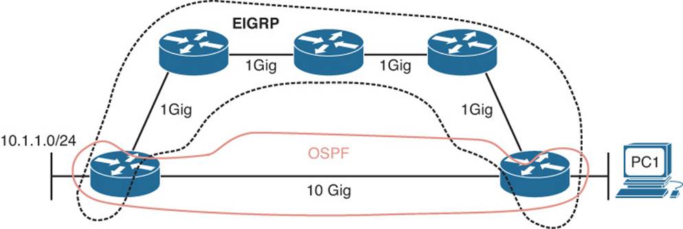
Figure 14-1 Using EIGRP Path Which Is Suboptimal
Being able to recognize when a certain routing source should be used and when it should not be used is key to optimizing your network and reducing the number of troubleshooting instances related to “the network is slow.” In this case, we might want to consider increasing the AD of EIGRP or lowering the AD of OSPF to optimize routing.
Route Filtering
A distribute list applied to an EIGRP process controls which routes are advertised to neighbors or which routes are received from neighbors. The distribute list is applied in EIGRP configuration mode either inbound or outbound, and the routes sent or received are controlled by ACLs, prefix lists, or route maps. So, when troubleshooting route filtering, you need to consider the following:
![]() Is the distribute list applied in the correct direction?
Is the distribute list applied in the correct direction?
![]() Is the distribute list applied to the correct interface?
Is the distribute list applied to the correct interface?
![]() If the distribute list is using an ACL, is the ACL correct?
If the distribute list is using an ACL, is the ACL correct?
![]() If the distribute list is using a prefix list, is the prefix list correct?
If the distribute list is using a prefix list, is the prefix list correct?
![]() If the distribute list is using a route map, is the route map correct?
If the distribute list is using a route map, is the route map correct?
The show ip protocols command will identify whether a distribute list is applied to all interfaces or an individual interface, as shown in Example 14-21. This example indicates that there are no outbound filters and that there is an inbound filter on Gig1/0.
Example 14-21 Verifying Route Filters with show ip protocols
R1#show ip protocols
*** IP Routing is NSF aware ***
Routing Protocol is "eigrp 100"
Outgoing update filter list for all interfaces is not set
Incoming update filter list for all interfaces is not set
GigabitEthernet1/0 filtered by 10 (per-user), default is not set
Default networks flagged in outgoing updates
Default networks accepted from incoming updates
EIGRP-IPv4 Protocol for AS(100)
Metric weight K1=1, K2=0, K3=1, K4=0, K5=0
NSF-aware route hold timer is 240
Router-ID: 10.1.12.1
...output omitted...
The inbound filter in Example 14-21 on Gig1/0 is filtering with ACL 10. To verify the entries in the ACL, you must issue the show access-lists 10 command. If a prefix list was applied, you issue the show ip prefix-list command. If a route map was applied you issue the show route-mapcommand.
As displayed in Example 14-22, you can verify the command that was used to apply the distribute list in the running configuration by reviewing the EIGRP configuration section.
Example 14-22 Verifying EIGRP distribute-list Command
R1#show run | section router eigrp
router eigrp 100
distribute-list 10 in GigabitEthernet1/0
network 10.1.1.1 0.0.0.0
network 10.1.12.1 0.0.0.0
passive-interface GigabitEthernet0/0
Stub Configuration
The EIGRP stub feature allows you to control the scope of EIGRP queries in the network. Figure 14-2 shows the failure of network 192.168.1.0/24 on R1 that causes a query to be sent to R2 and then a query from R2 sent to R3 and R4. However, the query to R3 is not needed because R3 will never have alternate information about the 192.168.1.0/24 network. The query wastes resources. Configuring the EIGRP stub feature on R3 with the eigrp stub command will ensure that R2 never sends a query to R3, as shown in Figure 14-3.
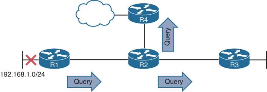
Figure 14-2 Query Scope Without EIGRP Stub Feature
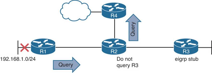
Figure 14-3 Query Scope with EIGRP Stub Feature
This feature comes in handy over slow hub-and-spoke WAN links, as shown in Figure 14-4. It prevents the hub from querying the spokes, which reduces the amount of EIGRP traffic sent over the link. In addition, it reduces the chance of a route being stuck-in-active (SIA). SIA happens when a router does not receive a reply to a query that it sent. Over WANs, this can happen due to congestion and result in the reestablishment of neighbor relationships, which causes convergence, which generates even more EIGRP traffic. Therefore, if we do not query the hubs, we do not have to worry about these issues.
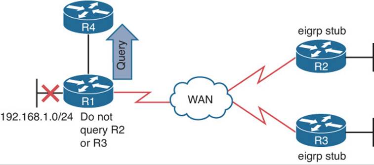
Figure 14-4 EIGRP Stub Feature over WAN Links
When configuring the EIGRP stub feature, you can control the routes that the stub router will advertise to its neighbor. By default, it is connected and summary routes. However, you have the option of just connected, summary, redistributed, static, or a combination of them. The other option is to send no routes (receive-only). If the wrong option is chosen, the stub routers would not be advertising the correct routes to its neighbors, resulting in missing routes on the hub and other routers in the topology. In addition, if you configure the wrong router as the stub router (for example, R1 in Figure 14-4), R1 would never fully share all routes it knows about to R4, R2, and R3, resulting in missing routes in the topology. To verify whether the router is a stub router and the routes it will advertise, issue the show ip protocols command, as shown in Example 14-23.
Example 14-23 show ip protocols Command Output on R2
R2#show ip protocols
...output omitted...
EIGRP-IPv4 Protocol for AS(100)
Metric weight K1=1, K2=0, K3=1, K4=0, K5=0
NSF-aware route hold timer is 240
Router-ID: 192.1.1.1
Stub, connected, summary
Topology : 0 (base)
Active Timer: 3 min
Distance: internal 90 external 170
Maximum path: 4
...output omitted...
To determine whether a neighbor is a stub router and the types of routes it is advertising, issue the command show ip eigrp neighbors detail. Example 14-24 displays the output of show ip eigrp neighbors detail on R1 and indicates that the neighbor is a stub router advertising connected and summary routes.
Example 14-24 Verifying Whether an EIGRP Neighbor Is a Stub Router
R1#show ip eigrp neighbors detail
EIGRP-IPv4 Neighbors for AS(100)
H Address Interface Hold Uptime SRTT RTO Q Seq
(sec) (ms) Cnt Num
0 10.1.13.1 Se1/0 14 00:00:18 99 594 0 11
Version 11.0/2.0, Retrans: 0, Retries: 0, Prefixes: 2
Topology-ids from peer - 0
Stub Peer Advertising (CONNECTED SUMMARY ) Routes
Suppressing queries
...output omitted...
Interface Is Shut Down
As discussed earlier, the network command enables the routing process on an interface. Once the EIGRP process is enabled on the interface, the network the interface is part of (the directly connected entry in the routing table) is injected into the EIGRP process. If the interface is shut down, there is no directly connected entry for the network in the routing table. Therefore, the network does not exist, and there is no network that can be injected into the EIGRP process. The interface has to be up/up for routes to be advertised or for neighbor relationships to be formed.
Split-horizon
The EIGRP split-horizon rule states that any routes learned inbound on an interface will not be advertised out the same interface. This rule is designed to prevent routing loops. However, this rule presents an issue in certain topologies. Figure 14-5 shows a nonbroadcast multiaccess (NBMA)Frame Relay hub-and-spoke topology or a dynamic multipoint virtual private network (DMVPN), which both use multipoint interfaces on the hub. The multipoint interface (single physical interface or mGRE tunnel interface) provides connectivity to multiple routers in the same subnet out the single interface, like Ethernet. In this figure, R2 is sending an EIGRP update to R1 on the permanent virtual circuit (PVC) or generic routing encapsulation (GRE) tunnel. Because split-horizon is enabled on the Ser1/0 interface or the multipoint GRE tunnel interface on R1, R1 will not advertise the 10.1.2.0/24 network back out that interface. So, R3 will never learn about 10.1.2.0/24.
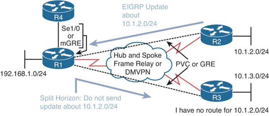
Figure 14-5 EIGRP Split-Horizon Issue
To verify whether split-horizon is enabled on an interface, issue the show ip interface interface_type interface_number command, as shown in Example 14-25. In this case, you can see that split-horizon is enabled.
Example 14-25 Verifying Whether Split-horizon Is Enabled on an Interface
R1#show ip interface tunnel 0
Tunnel0 is up, line protocol is up
Internet address is 192.168.1.1/24
Broadcast address is 255.255.255.255
Address determined by setup command
MTU is 1476 bytes
Helper address is not set
Directed broadcast forwarding is disabled
Outgoing access list is not set
Inbound access list is not set
Proxy ARP is enabled
Local Proxy ARP is disabled
Security level is default
Split horizon is enabled
ICMP redirects are never sent
...output omitted...
To disable split-horizon on an interface completely, issue the no ip split-horizon command in interface configuration mode. If you only want to disable it for the EIGRP process running on the interface, issue the command no ip split-horizon eigrp autonomous_system_number.
If you disable split-horizon for the EIGRP process, it will still show as enabled in the output of show ip interface, as shown in Example 14-25 earlier. To verify whether split-horizon is enabled or disabled for the EIGRP process on an interface, issue the command show ip eigrp interfaces detail interface_type interface_number. Example 14-26 shows that it is disabled for EIGRP on interface tunnel 0.
Example 14-26 Verifying Whether Split-horizon Is Enabled for EIGRP on an Interface
R1#show ip eigrp interfaces detail tunnel 0
EIGRP-IPv4 Interfaces for AS(100)
Xmit Queue PeerQ Mean Pacing Time Multicast Pending
Interface Peers Un/Reliable Un/Reliable SRTT Un/Reliable Flow Timer Routes
Tu0 0 0/0 0/0 0 6/6 0 0
Hello-interval is 5, Hold-time is 15
Split-horizon is disabled
Next xmit serial <none>
Packetized sent/expedited: 0/0
Hello's sent/expedited: 17/1
Un/reliable mcasts: 0/0 Un/reliable ucasts: 0/0
Mcast exceptions: 0 CR packets: 0 ACKs suppressed: 0
Retransmissions sent: 0 Out-of-sequence rcvd: 0
Topology-ids on interface - 0
Authentication mode is not set
Troubleshooting Miscellaneous EIGRP for IPv4 Issues
So far, your focus has been on troubleshooting EIGRP neighbor relationships and routes. Now your focus will be on troubleshooting issues related to feasible successors, discontiguous networks and autosummarization, route summarization, and equal and unequal metric load balancing.
Feasible Successors
The best route (lowest feasible distance [FD] metric) for a specific network in the EIGRP topology table becomes a candidate to be injected into the router’s routing table. (We use the term candidate because even though it is the best EIGRP route, there might be a better source of the same information that will be used instead.) If that route is indeed injected into the routing table, that route becomes known as the successor (best) route. This is the route that is then advertised to neighboring routers. Example 14-27 displays a sample EIGRP topology table, which you can view by issuing the show ip eigrp topology command. Focus on the entry for 172.16.32.192/29. Notice that there are three paths to reach that network. However, based on the fact that it states 1 successors, only one is being used as the best path. It is the one with the lowest FD of 2174976, which is the path via 172.16.33.5, reachable out interface Serial 1/0.
Example 14-27 Sample show ip eigrp topology Command Output
R4#show ip eigrp topology
EIGRP-IPv4 Topology Table for AS(100)/ID(192.4.4.4)
Codes: P - Passive, A - Active, U - Update, Q - Query, R - Reply,
r - reply Status, s - sia Status
...output omitted...
P 10.1.13.0/24, 1 successors, FD is 3072
via 10.1.34.3 (3072/2816), GigabitEthernet2/0
P 0.0.0.0/0, 1 successors, FD is 28160
via Rstatic (28160/0)
P 192.1.1.1/32, 1 successors, FD is 131072
via 10.1.34.3 (131072/130816), GigabitEthernet2/0
P 172.16.32.192/29, 1 successors, FD is 2174976
via 172.16.33.5 (2174976/30720), Serial1/0
via 172.16.33.6 (2684416/2172416), Serial1/0
via 172.16.33.18 (2684416/2172416), Serial1/2
P 198.51.100.0/30, 1 successors, FD is 28416
via 10.1.34.3 (28416/28160), GigabitEthernet2/0
P 172.16.33.12/30, 1 successors, FD is 2172416
via 172.16.33.5 (2172416/28160), Serial1/0
...output omitted...
In the brackets after the next-hop IP address is the FD followed by the reported distance (RD):
![]() Reported distance: The distance from the neighbor at the next-hop address to the destination network
Reported distance: The distance from the neighbor at the next-hop address to the destination network
![]() Feasible distance: The RD plus the metric to reach the neighbor at the next-hop address that is advertising the RD
Feasible distance: The RD plus the metric to reach the neighbor at the next-hop address that is advertising the RD
The successor is the path with the lowest FD. However, EIGRP also precalculates paths that could be used if the successor disappeared. These are known as the feasible successors. To be a feasible successor, the RD of the path to become a feasible successor must be less than the FD of the successor. Review Example 14-27 again. The path via 172.16.33.5 is the successor. However, are the paths using 172.16.33.6 and 172.16.33.18 feasible successors (backups)? To determine this, take the RD of these paths (in this case, it is the same [2172416]), and compare it to the FD of the successor (2174976). Is the RD less than the FD? Yes. Therefore, they are feasible successors.
For troubleshooting, it is important to note that the output of show ip eigrp topology only displays the successors and feasible successors. If you need to verify the FD or RD of other paths to the same destination that are not feasible successors, you can use the show ip eigrp topology all-links command. Example 14-28 displays the output of show ip eigrp topology and show ip eigrp topology all-links. Focus on the entry for 10.1.34.0/24. Notice how in the output of show ip eigrp topology there is only one path listed and in the output of show ip eigrp topology all-linksthere are two. This is because the next hop of 172.16.33.13 has an RD greater than the FD of the successor and therefore cannot be a feasible successor.
Example 14-28 Sample show ip eigrp topology Comparison
Router#show ip eigrp topology
EIGRP-IPv4 Topology Table for AS(100)/ID(172.16.33.14)
Codes: P - Passive, A - Active, U - Update, Q - Query, R - Reply,
r - reply Status, s - sia Status
P 172.16.33.8/30, 1 successors, FD is 2169856
via Connected, Serial1/0
P 10.1.34.0/24, 1 successors, FD is 2682112
via 172.16.33.9 (2682112/2170112), Serial1/0
P 203.0.113.0/30, 1 successors, FD is 2684416
via 172.16.33.9 (2684416/2172416), Serial1/0
P 172.16.32.192/29, 1 successors, FD is 28160
via Connected, FastEthernet2/0
P 172.16.33.12/30, 1 successors, FD is 5511936
via Connected, Serial1/1
P 172.16.33.0/29, 1 successors, FD is 2681856
via 172.16.33.9 (2681856/2169856), Serial1/0
Router#show ip eigrp topology all-links
EIGRP-IPv4 Topology Table for AS(100)/ID(172.16.33.14)
Codes: P - Passive, A - Active, U - Update, Q - Query, R - Reply,
r - reply Status, s - sia Status
P 172.16.33.8/30, 1 successors, FD is 2169856, serno 1
via Connected, Serial1/0
P 10.1.34.0/24, 1 successors, FD is 2682112, serno 8
via 172.16.33.9 (2682112/2170112), Serial1/0
via 172.16.33.13 (6024192/3072256), Serial1/1
P 203.0.113.0/30, 1 successors, FD is 2684416, serno 9
via 172.16.33.9 (2684416/2172416), Serial1/0
via 172.16.33.13 (6026496/3074560), Serial1/1
P 172.16.32.192/29, 1 successors, FD is 28160, serno 3
via Connected, FastEthernet2/0
P 172.16.33.12/30, 1 successors, FD is 5511936, serno 2
via Connected, Serial1/1
P 172.16.33.0/29, 1 successors, FD is 2681856, serno 5
via 172.16.33.9 (2681856/2169856), Serial1/0
via 172.16.33.13 (6023936/3072000), Serial1/1
The EIGRP topology table not only contains the routes learned from other routers, but also routes that have been redistributed into the EIGRP process and the local networks whose interfaces are participating in the EIGRP process, as highlighted in Example 14-29.
Example 14-29 Verifying Connected and Redistributed Entries in the Topology Table
R4#show ip eigrp topology
EIGRP-IPv4 Topology Table for AS(100)/ID(192.4.4.4)
Codes: P - Passive, A - Active, U - Update, Q - Query, R - Reply,
r - reply Status, s - sia Status
...output omitted...
P 192.2.2.2/32, 1 successors, FD is 131072
via 10.1.34.3 (131072/130816), GigabitEthernet2/0
P 10.1.13.0/24, 1 successors, FD is 3072
via 10.1.34.3 (3072/2816), GigabitEthernet2/0
P 0.0.0.0/0, 1 successors, FD is 28160
via Rstatic (28160/0)
P 192.1.1.1/32, 1 successors, FD is 131072
via 10.1.34.3 (131072/130816), GigabitEthernet2/0
P 172.16.32.192/29, 1 successors, FD is 2174976
via 172.16.33.5 (2174976/30720), Serial1/0
via 172.16.33.6 (2684416/2172416), Serial1/0
via 172.16.33.18 (2684416/2172416), Serial1/2
P 198.51.100.0/30, 1 successors, FD is 28416
via 10.1.34.3 (28416/28160), GigabitEthernet2/0
P 172.16.33.12/30, 1 successors, FD is 2172416
via 172.16.33.5 (2172416/28160), Serial1/0
P 192.6.6.6/32, 2 successors, FD is 2297856
via 172.16.33.6 (2297856/128256), Serial1/0
via 172.16.33.18 (2297856/128256), Serial1/2
P 172.16.33.0/29, 1 successors, FD is 2169856
via Connected, Serial1/0
...output omitted...
Discontiguous Networks and Autosummarization
EIGRP supports variable-length subnet masking (VLSM). In earlier releases of the Cisco IOS (pre 15.0), EIGRP automatically performed route summarization at classful network boundaries. This was an issue in networks containing discontiguous networks. As a result, it was necessary when configuring EIGRP to turn off automatic summarization using the no auto-summary command in router configuration mode for an EIGRP autonomous system. However, from Cisco IOS 15.0 and onward, automatic summarization is off by default for EIGRP. Therefore, you do not have to worry about issuing the no auto-summary command anymore. However, you should be able to recognize a discontiguous network when reviewing a network topology and understand that if someone manually enabled autosummarization in your EIGRP autonomous system, routing would be broken.
Figure 14-6 provides an example of a discontiguous network. The 172.16.0.0/16 Class B classful network is considered discontiguous because it is subnetted as 172.16.1.0/24 and 172.16.2.0/24 and the subnets are separated from each other by a different classful network, which is 10.0.0.0. With automatic summarization turned on, when R3 advertises the 172.16.2.0/24 network to R2, it is summarized to 172.16.0.0/16 because it is being sent out an interface in a different classful network. So, instead of 172.16.2.0/24 being sent, 172.16.0.0/16 is sent. Likewise, the same thing happens when R1 advertises the 172.16.1.0/24 network to R2; it is advertised as 172.16.0.0/16. If you reviewed R2’s routing table, it would show an entry for 172.16.0.0 with two next hops (if everything else is equal), one via R3 using Fa0/1 and the other via R1 using Fa0/0.
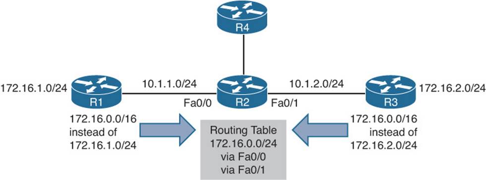
Figure 14-6 Discontiguous Network Example
Now picture a packet arriving at R2 from R4 with a destination IP of 172.16.2.5. Which way does R2 send it? You see the problem? It should send it out Fa0/1, but it could send it out Fa0/0. There is a 50/50 chance it gets it correct. The moral of this story is this: If you have a discontiguous network, autosummarization has to be off, and you must take care when performing manual summarization. To verify whether automatic summarization is enabled or disabled, use the show ip protocols command, as shown in Example 14-30.
Example 14-30 Verifying Route Summarization with show ip protocols
Router#show ip protocols
...output omitted...
EIGRP-IPv4 Protocol for AS(100)
Metric weight K1=1, K2=0, K3=1, K4=0, K5=0
NSF-aware route hold timer is 240
Router-ID: 10.1.13.1
Topology : 0 (base)
Active Timer: 3 min
Distance: internal 90 external 170
Maximum path: 4
Maximum hopcount 100
Maximum metric variance 1
Automatic Summarization: disabled
Address Summarization:
10.1.0.0/20 for Gi2/0
Summarizing 2 components with metric 2816
Maximum path: 4
Routing for Networks:
...output omitted...
Route Summarization
By default with IOS 15.0 and later, autosummary is off. Therefore, you can either turn it on (not recommended), or perform manual route summarization (recommended). With EIGRP, manual route summarization is enabled on an interface-by-interface basis. Therefore, when troubleshooting route summarization, keep the following in mind:
![]() Did you enable route summarization on the correct interface?
Did you enable route summarization on the correct interface?
![]() Did you associate the summary route with the correct EIGRP autonomous system?
Did you associate the summary route with the correct EIGRP autonomous system?
![]() Did you create the appropriate summary route?
Did you create the appropriate summary route?
You can verify all of these using the show ip protocols command, as shown in Example 14-30. In this example, autosummarization is disabled, and manual summarization is enabled for EIGRP autonomous system 100 on interface Gigabit Ethernet 2/0 for 10.1.0.0/20.
It is important that you create accurate summary routes to ensure that your router is not advertising networks in the summary route that it does not truly know how to reach. If it does, it is possible that it might receive packets to destinations that fall within the summary that it really does not know how to reach. If this is the case, it means that packets will be dropped because of the route to null 0.
When a summary route is created on a router, so is a summary route to null 0, as shown in Example 14-31. This route to null 0 is created to prevent routing loops. It is imperative that this route is in the table to ensure that if a packet is received by this router destined to a network that falls within the summary that the router does not really know how to reach, it will be dropped. If the route to null 0 did not exist, and there was a default route on the router, the router would forward the packet via the default route, and then the next-hop router would end up forwarding it back to this router, because it is using the summary route, then the local router would then forward it based on the default route, and then it would come back. This is a routing loop.
Example 14-31 Verifying Local Summary Route to Null 0
Router#show ip route | include Null
D 10.1.0.0/20 is a summary, 00:12:03, Null0
The route to null 0 has an AD of 5, as shown in Example 14-32, to ensure that it is more trustworthy than most of the other sources of routing information. Therefore, the only way this route would not be in the routing table is if you had a source with a lower AD (for example, someone creates a static route for the same summary network and points it to a next hop IP address instead of null 0). This would cause a routing loop.
Example 14-32 Verifying the AD of Local Summary Route to Null 0
Router#show ip route 10.1.0.0
Routing entry for 10.1.0.0/20
Known via "eigrp 100", distance 5, metric 2816, type internal
Load Balancing
By default, EIGRP will load balance on four equal metric paths. You can change this with the maximum-paths command in router configuration mode for EIGRP. However, EIGRP also supports load balancing across unequal metric paths using the variance feature. By default, the variance value for an EIGRP routing process is 1, meaning the load balancing will only occur over equal metric paths. You can issue the variance multiplier command in router configuration mode to specify a range of metrics over which load balancing will occur. For example, suppose that a route had a metric of 200000, and you configured the variance 2 command for the EIGRP routing process. This would cause load balancing to occur over any route with a metric in the range of 200000 through 400000 (2 * 200000). As you can see, a route could have a metric as high as 400000 (that is, the variance multiplier multiplied by the best metric) and still be used.
However, even with unequal metric load balancing, you are still governed by the maximum-paths command. Therefore, if you have five unequal-metric paths that you want to use and you configured the correct variance multiplier, but maximum paths is set to 2, you will only use two of the five paths. To use all five, you would also need to make sure that the maximum paths were set to 5 as well.
Also, remember that the feasibility condition plays a huge role in unequal path load balancing. If the path is not a feasible successor, it cannot be used for unequal path load balancing. There is no exception to this rule. If you recall, the feasibility condition is this: To be a feasible successor, your RD must be less than the FD of the successor.
To verify the configured maximum paths and variance, use the show ip protocols command, as shown in Example 14-33.
Example 14-33 Verifying Variance and Maximum Paths
Router#show ip protocols
Routing Protocol is "eigrp 100"
Outgoing update filter list for all interfaces is not set
Incoming update filter list for all interfaces is not set
Default networks flagged in outgoing updates
Default networks accepted from incoming updates
EIGRP-IPv4 Protocol for AS(100)
Metric weight K1=1, K2=0, K3=1, K4=0, K5=0
NSF-aware route hold timer is 240
Router-ID: 10.1.12.1
Topology : 0 (base)
Active Timer: 3 min
Distance: internal 90 external 170
Maximum path: 4
Maximum hopcount 100
Maximum metric variance 1
Automatic Summarization: disabled
Maximum path: 4
Routing for Networks:
0.0.0.0
Routing Information Sources:
Gateway Distance Last Update
Gateway Distance Last Update
10.1.12.2 90 10:26:36
Distance: internal 90 external 170
EIGRP for IPv4 Trouble Tickets
This section presents various trouble tickets relating to the topics discussed earlier in the chapter. The purpose of these trouble tickets is to give a process that you can follow when troubleshooting in the real world or in an exam environment. All trouble tickets in this section are based on the topology depicted in Figure 14-7.
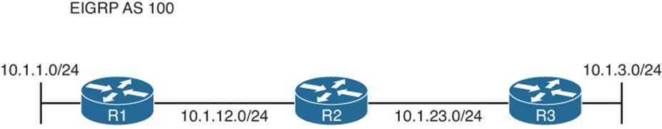
Figure 14-7 EIGRP for IPv4 Trouble Tickets Topology
Trouble Ticket 14-1
Problem: Users in the 10.1.1.0/24 network indicate that they are not able to access resources in the 10.1.3.0/24 network.
As always, the first item on the list for troubleshooting is: verify the problem. You access a PC in the 10.1.1.0/24 network and ping an IP address in the 10.1.3.0/24 network and it is successful (0% loss), as shown in Example 14-34. However, notice that the reply is from the default gateway at 10.1.1.1 and it states: Destination host unreachable. Therefore, it was technically not successful.
Example 14-34 Destination Unreachable Result from ping Command on PC
C:\>ping 10.1.3.10
Pinging 10.1.3.10 with 32 bytes of data;
Reply from 10.1.1.1: Destination host unreachable.
Reply from 10.1.1.1: Destination host unreachable.
Reply from 10.1.1.1: Destination host unreachable.
Reply from 10.1.1.1: Destination host unreachable.
Ping statistics for 10.1.3.10:
Packets: Sent = 4, Received = 4, lost = 0 (0% loss),
Approximate round trip times in milli-seconds:
Minimum = 0ms, Maximum = 0ms, Average = 0ms
The result of this ping tells us two very important things: The PC can reach the default gateway, and the default gateway does not know how to get to the 10.1.3.0/24 network. Therefore, we can focus our attention on R1 and work from there.
On R1, you issue the same ping, but it fails, as shown in Example 14-35.
Example 14-35 Failed Ping from R1 to 10.1.3.10
R1#ping 10.1.3.10
Type escape sequence to abort.
Sending 5, 100-byte ICMP Echos to 10.1.3.10, timeout is 2 seconds:
.....
Success rate is 0 percent (0/5)
Next, you check R1’s routing table with the show ip route command and notice that there are only connected routes in the routing table, as shown in Example 14-36. You conclude that R1 is not learning any routes from R2.
Example 14-36 show ip route Output on R1
R1#show ip route
...output omitted...
Gateway of last resort is not set
10.0.0.0/8 is variably subnetted, 4 subnets, 2 masks
C 10.1.1.0/24 is directly connected, GigabitEthernet0/0
L 10.1.1.1/32 is directly connected, GigabitEthernet0/0
C 10.1.12.0/24 is directly connected, GigabitEthernet1/0
L 10.1.12.1/32 is directly connected, GigabitEthernet1/0
According to Figure 14-7, EIGRP is the routing protocol in use. Therefore, you issue the show ip protocols command to verify that EIGRP is running the correct autonomous system. Example, 14-37 displays the show ip protocols output and confirms that EIGRP 100 is in operation on R1.
Example 14-37 show ip protocols Output on R1
R1#show ip protocols
*** IP Routing is NSF aware ***
Routing Protocol is "eigrp 100"
Outgoing update filter list for all interfaces is not set
Incoming update filter list for all interfaces is not set
Default networks flagged in outgoing updates
Default networks accepted from incoming updates
EIGRP-IPv4 Protocol for AS(100)
Metric weight K1=1, K2=0, K3=1, K4=0, K5=0
NSF-aware route hold timer is 240
Router-ID: 10.1.12.1
Topology : 0 (base)
Active Timer: 3 min
Distance: internal 90 external 170
Maximum path: 4
Maximum hopcount 100
Maximum metric variance 1
Automatic Summarization: disabled
Maximum path: 4
Routing for Networks:
10.1.1.1/32
10.1.12.1/32
Routing Information Sources:
Gateway Distance Last Update
10.1.12.2 90 00:45:53
Distance: internal 90 external 170
Next you check to see whether R1 has any EIGRP neighbors. According to the topology, R2 should be a neighbor. To verify EIGRP neighbors, you issue the show ip eigrp neighbors command on R1, as shown in Example 14-38. According to the output, R1 has no neighbors.
Example 14-38 show ip eigrp neighbors Output on R1
R1#show ip eigrp neighbors
EIGRP-IPv4 Neighbors for AS(100)
Now you verify whether there are any interfaces participating in the EIGRP process using the show ip eigrp interfaces command. Example 14-39 indicates that there are two interfaces participating in the EIGRP process: Gig0/0 and Gig1/0.
Example 14-39 show ip eigrp interfaces Output on R1
R1#show ip eigrp interfaces
EIGRP-IPv4 Interfaces for AS(100)
Xmit Queue PeerQ Mean Pacing Time Multicast Pending
Interface Peers Un/Reliable Un/Reliable SRTT Un/Reliable Flow Timer Routes
Gi0/0 0 0/0 0/0 0 0/0 0 0
Gi1/0 0 0/0 0/0 0 0/0 304 0
The output of show cdp neighbors, as shown in Example 14-40, indicates that R1 is connected to R2 using Gig1/0 and that R2 is using Gig0/0. Therefore, we expect a peering between the two using these interfaces.
Example 14-40 show cdp neighbors Output on R1
R1#show cdp neighbors
Capability Codes: R - Router, T - Trans Bridge, B - Source Route Bridge
S - Switch, H - Host, I - IGMP, r - Repeater, P - Phone,
D - Remote, C - CVTA, M - Two-port Mac Relay
Device ID Local Intrfce Holdtme Capability Platform Port ID
R2 Gig 1/0 172 R 7206VXR Gig 0/0
Now is a great time to verify whether Gig0/0 on R2 is participating in the EIGRP process. On R2, you issue the show ip eigrp interfaces command, as shown in Example 14-41.
Example 14-41 show ip eigrp interfaces Output on R2
R2#show ip eigrp interfaces
EIGRP-IPv4 Interfaces for AS(100)
Xmit Queue PeerQ Mean Pacing Time Multicast Pending
Interface Peers Un/Reliable Un/Reliable SRTT Un/Reliable Flow Timer Routes
Gi1/0 0 0/0 0/0 0 0/0 448 0
Example 14-41 confirms that R2’s interface Gig0/0 is not participating in the EIGRP process.
You review the output of show run | section router eigrp and show ip interface brief on R2, as shown in Example 14-42, and confirm that the wrong network statement was issued on R2. The network statement network 10.1.21.2 0.0.0.0 enables the EIGRP process on the interface with that IP address. According to the output of show ip interface brief, the network statement should be network 10.1.12.2 0.0.0.0.
Example 14-42 show run | section router eigrp Output on R2 and Verifying Interface IP address
R2#show run | section router eigrp
router eigrp 100
network 10.1.21.2 0.0.0.0
network 10.1.23.2 0.0.0.0
R2#show ip interface brief
Interface IP-Address OK? Method Status Protocol
Ethernet0/0 unassigned YES unset administratively down down
GigabitEthernet0/0 10.1.12.2 YES manual up up
GigabitEthernet1/0 10.1.23.2 YES manual up up
To fix this issue, on R2 you execute the no network 10.1.21.2 0.0.0.0 command and enter the network 10.1.12.2 0.0.0.0 command in router EIGRP configuration mode instead. After you have done this, the neighbor relationship forms, as shown with the following syslog messages:
R1#
%DUAL-5-NBRCHANGE: EIGRP-IPv4 100: Neighbor 10.1.12.2 (GigabitEthernet1/0)
is up: new adjacency
R2#
%DUAL-5-NBRCHANGE: EIGRP-IPv4 100: Neighbor 10.1.12.1 (GigabitEthernet0/0)
is up: new adjacency
You confirm the neighbor relationship on R1 with the show ip eigrp neighbors command, as shown in Example 14-43.
Example 14-43 Verifying Neighbors with the show ip eigrp neighbors Command
R1#show ip eigrp neighbors
EIGRP-IPv4 Neighbors for AS(100)
H Address Interface Hold Uptime SRTT RTO Q Seq
(sec) (ms) Cnt Num
0 10.1.12.2 Gi1/0 14 00:02:10 75 450 0 12
You go back to the PC and ping the same IP address to confirm the problem is solved, and you receive the same result, as shown in Example 14-44. R1 still does not know about the 10.1.3.0/24 network.
Example 14-44 Destination Unreachable from ping Command on PC
C:\>ping 10.1.3.10
Pinging 10.1.3.10 with 32 bytes of data;
Reply from 10.1.1.1: Destination host unreachable.
Reply from 10.1.1.1: Destination host unreachable.
Reply from 10.1.1.1: Destination host unreachable.
Reply from 10.1.1.1: Destination host unreachable.
Ping statistics for 10.1.3.10:
Packets: Sent = 4, Received = 4, lost = 0 (0% loss),
Approximate round trip times in milli-seconds:
Minimum = 0ms, Maximum = 0ms, Average = 0ms
Back on R1, you issue the show ip route command, as shown in Example 14-45. R1 is receiving EIGRP routes because there is now an EIGRP route (D) in the routing table. However, R1 still does not know about the 10.1.3.0/24 network.
Example 14-45 show ip route Output After Neighbor Relationship with R2 Established
R1#show ip route
...output omitted...
Gateway of last resort is not set
10.0.0.0/8 is variably subnetted, 5 subnets, 2 masks
C 10.1.1.0/24 is directly connected, GigabitEthernet0/0
L 10.1.1.1/32 is directly connected, GigabitEthernet0/0
C 10.1.12.0/24 is directly connected, GigabitEthernet1/0
L 10.1.12.1/32 is directly connected, GigabitEthernet1/0
D 10.1.23.0/24 [90/3072] via 10.1.12.2, 00:07:40, GigabitEthernet1/0
Does R2 know about the 10.1.3.0/24 network? Example 14-46 displays R2’s routing table, and it is missing 10.1.3.0/24 as well.
Example 14-46 show ip route Output on R2
R2#show ip route
...output omitted...
Gateway of last resort is not set
10.0.0.0/8 is variably subnetted, 5 subnets, 2 masks
D 10.1.1.0/24 [90/3072] via 10.1.12.1, 00:12:11, GigabitEthernet0/0
C 10.1.12.0/24 is directly connected, GigabitEthernet0/0
L 10.1.12.2/32 is directly connected, GigabitEthernet0/0
C 10.1.23.0/24 is directly connected, GigabitEthernet1/0
L 10.1.23.2/32 is directly connected, GigabitEthernet1/0
For R2 to learn about the network, it has to be neighbors with R3. Reviewing the R2 output of show ip eigrp neighbors in Example 14-47 indicates that R3 is not a neighbor, only R1.
Example 14-47 show ip eigrp neighbors on R2
R2#show ip eigrp neighbors
EIGRP-IPv4 Neighbors for AS(100)
H Address Interface Hold Uptime SRTT RTO Q Seq
(sec) (ms) Cnt Num
0 10.1.12.1 Gi0/0 11 00:17:28 65 390 0 7
Previously, Example 14-41 indicated that Gig1/0 on R2 was participating in the EIGRP process. Therefore, we should look at the interfaces on R3. According to the output in Example 14-48, both interfaces on R3 are participating in the EIGRP process for autonomous system 10.
Example 14-48 show ip eigrp interfaces on R3
R3#show ip eigrp interfaces
EIGRP-IPv4 Interfaces for AS(10)
Xmit Queue PeerQ Mean Pacing Time Multicast Pending
Interface Peers Un/Reliable Un/Reliable SRTT Un/Reliable Flow Timer Routes
Gi0/0 0 0/0 0/0 0 0/0 0 0
Gi1/0 0 0/0 0/0 0 0/0 0 0
Did you spot the issue? If not, look again at Example 14-48. If you need to compare it to Example 14-47, do so.
The autonomous system numbers do not match, and to form an EIGRP neighbor relationship, the autonomous system numbers must match. To solve this issue, you must enable EIGRP autonomous system 100 on R3, and then provide the correct network statements to enable EIGRP on the required interfaces for autonomous system 100. You should also remove any EIGRP configs that are not needed, such as the EIGRP autonomous system 10 configurations. Example 14-49 provides the commands needed to accomplish this.
Example 14-49 R3 Configurations Required to Solve Issue
R3#config t
Enter configuration commands, one per line. End with CNTL/Z.
R3(config)#no router eigrp 10
R3(config)#router eigrp 100
R3(config-router)#network 10.1.3.3 0.0.0.0
R3(config-router)#network 10.1.23.3 0.0.0.0
%DUAL-5-NBRCHANGE: EIGRP-IPv4 100: Neighbor 10.1.23.2 (GigabitEthernet1/0) is up:
new adjacency
R3(config-router)#
Notice in Example 14-49 that the neighbor relationship with R2 was successful. Now it is time to verify that all our issues are solved. On R2, you issue the show ip route command, as shown in Example 14-50, and notice that the 10.1.3.0/24 network is present. You also issue the same command on R1 and notice that 10.1.3.0/24 is present, as shown in Example 14-51. You then ping from the PC again, and the ping is truly successful, as shown in Example 14-52.
Example 14-50 show ip route Output on R2
R2#show ip route
...output omitted...
Gateway of last resort is not set
10.0.0.0/8 is variably subnetted, 6 subnets, 2 masks
D 10.1.1.0/24 [90/3072] via 10.1.12.1, 00:37:21, GigabitEthernet0/0
D 10.1.3.0/24 [90/3072] via 10.1.23.3, 00:06:16, GigabitEthernet1/0
C 10.1.12.0/24 is directly connected, GigabitEthernet0/0
L 10.1.12.2/32 is directly connected, GigabitEthernet0/0
C 10.1.23.0/24 is directly connected, GigabitEthernet1/0
L 10.1.23.2/32 is directly connected, GigabitEthernet1/0
Example 14-51 show ip route Output on R1
R1#show ip route
Codes: L - local, C - connected, S - static, R - RIP, M - mobile, B - BGP
D - EIGRP, EX - EIGRP external, O - OSPF, IA - OSPF inter area
N1 - OSPF NSSA external type 1, N2 - OSPF NSSA external type 2
E1 - OSPF external type 1, E2 - OSPF external type 2
i - IS-IS, su - IS-IS summary, L1 - IS-IS level-1, L2 - IS-IS level-2
ia - IS-IS inter area, * - candidate default, U - per-user static route
o - ODR, P - periodic downloaded static route, H - NHRP, l - LISP
+ - replicated route, % - next hop override
Gateway of last resort is not set
10.0.0.0/8 is variably subnetted, 6 subnets, 2 masks
C 10.1.1.0/24 is directly connected, GigabitEthernet0/0
L 10.1.1.1/32 is directly connected, GigabitEthernet0/0
D 10.1.3.0/24 [90/3328] via 10.1.12.2, 00:07:08, GigabitEthernet1/0
C 10.1.12.0/24 is directly connected, GigabitEthernet1/0
L 10.1.12.1/32 is directly connected, GigabitEthernet1/0
D 10.1.23.0/24 [90/3072] via 10.1.12.2, 00:38:12, GigabitEthernet1/0
Example 14-52 A Successful Ping from the 10.1.1.0/24 Network to the 10.1.3.0/24 Network
C:\>ping 10.1.3.10
Pinging 10.1.3.10 with 32 bytes of data:
Reply from 10.1.3.10: bytes=32 time 1ms TTL=128
Reply from 10.1.3.10: bytes=32 time 1ms TTL=128
Reply from 10.1.3.10: bytes=32 time 1ms TTL=128
Reply from 10.1.3.10: bytes=32 time 1ms TTL=128
Ping statistics for 10.1.3.10:
Packets: Sent = 4, Received = 4, Lost = 0 (0% loss),
Approximate round trip times in milli-seconds:
Minimum = 0ms, Maximum = 0ms, Average = 0ms
Trouble Ticket 14-2
Problem: Users in the 10.1.1.0/24 network have indicated that they are not able to access resources in 10.1.3.0/24.
To begin, you verify the problem by pinging from a PC in the 10.1.1.0/24 network to a PC in the 10.1.3.0/24 network, as shown in Example 14-53, and it fails. Notice that the reply is from the default gateway at 10.1.1.1 and it states: Destination host unreachable. Therefore, it was technically not successful.
Example 14-53 Destination Unreachable Result from ping Command on PC
C:\>ping 10.1.3.10
Pinging 10.1.3.10 with 32 bytes of data;
Reply from 10.1.1.1: Destination host unreachable.
Reply from 10.1.1.1: Destination host unreachable.
Reply from 10.1.1.1: Destination host unreachable.
Reply from 10.1.1.1: Destination host unreachable.
Ping statistics for 10.1.3.10:
Packets: Sent = 4, Received = 4, lost = 0 (0% loss),
Approximate round trip times in milli-seconds:
Minimum = 0ms, Maximum = 0ms, Average = 0ms
The result of this ping tells us two very important things: the PC can reach the default gateway, and the default gateway does not know how to get to the 10.1.3.0/24 network. Therefore, we can focus our attention on R1 and work from there.
On R1, you issue the same ping, but it fails, as shown in Example 14-54.
Example 14-54 Failed Ping from R1 to 10.1.3.10
R1#ping 10.1.3.10
Type escape sequence to abort.
Sending 5, 100-byte ICMP Echos to 10.1.3.10, timeout is 2 seconds:
.....
Success rate is 0 percent (0/5)
Next you check the routing table on R1 with the show ip route 10.1.3.0 255.255.255.0 command, as shown in Example 14-55, and it states: % Subnet not in table.
Example 14-55 Determining Whether a Route Is in R1’s Routing Table
R1#show ip route 10.1.3.0 255.255.255.0
% Subnet not in table
Does R2 know about it? You go to R2 and issue the same command, as shown in Example 14-56. The result is the same: % Subnet not in table.
Example 14-56 Determining Whether a Route Is in R2’s Routing Table
R2#show ip route 10.1.3.0 255.255.255.0
% Subnet not in table
Next you go to R3 and issue the same command. Notice that 10.1.3.0/24 is in the routing table as a connected route, as shown in Example 14-57.
Example 14-57 Determining Whether Route Is in R3’s Routing Table
R3#show ip route 10.1.3.0 255.255.255.0
Routing entry for 10.1.3.0/24
Known via "connected", distance 0, metric 0 (connected, via interface)
Redistributing via eigrp 100
Routing Descriptor Blocks:
* directly connected, via GigabitEthernet0/0
Route metric is 0, traffic share count is 1
What would prevent a connected route from being advertised via EIGRP to a neighbor? Answer: The interface is not participating in the EIGRP process. Now you check the EIGRP interface table on R3 with the show ip eigrp interfaces command. Example 14-58 indicates that only Gigabit Ethernet 1/0 is participating in the EIGRP process.
Example 14-58 Determining Whether an Interface Is Participating in the EIGRP Process
R3#show ip eigrp interfaces
EIGRP-IPv4 Interfaces for AS(100)
Xmit Queue PeerQ Mean Pacing Time Multicast Pending
Interface Peers Un/Reliable Un/Reliable SRTT Un/Reliable Flow Timer Routes
Gi1/0 1 0/0 0/0 821 0/0 4080 0
However, do not jump to the conclusion that this interface is not participating in the EIGRP process. Remember that EIGRP passive interfaces do not appear in this output. Therefore, check the output of show ip protocols for passive interfaces. In Example 14-59, you can see that there are no passive interfaces.
Example 14-59 Determining Whether an Interface Is Passive
R3#show ip protocols
*** IP Routing is NSF aware ***
Routing Protocol is "eigrp 100"
Outgoing update filter list for all interfaces is not set
Incoming update filter list for all interfaces is not set
Default networks flagged in outgoing updates
Default networks accepted from incoming updates
EIGRP-IPv4 Protocol for AS(100)
Metric weight K1=1, K2=0, K3=1, K4=0, K5=0
NSF-aware route hold timer is 240
Router-ID: 10.1.23.3
Topology : 0 (base)
Active Timer: 3 min
Distance: internal 90 external 170
Maximum path: 4
Maximum hopcount 100
Maximum metric variance 1
Automatic Summarization: disabled
Maximum path: 4
Routing for Networks:
10.1.3.0/32
10.1.23.3/32
Routing Information Sources:
Gateway Distance Last Update
10.1.23.2 90 00:19:11
Distance: internal 90 external 170
Now you need to make sure that there is a network statement that will enable the EIGRP process on the interface connected to the 10.1.3.0/24 network. In Example 14-59, the output of show ip protocols indicates that R3 is routing for networks 10.1.3.0/32. Remember from our discussion earlier that this really means network 10.1.3.0 0.0.0.0. As a result, EIGRP will be enabled on the interface with the IP address 10.1.3.0. Example 14-60, which displays the output of show ip interface brief, shows that there are no interfaces with that IP address. Interface Gig0/0 has an IP address of 10.1.3.3. Therefore, the network statement is incorrect, as shown in the output of show run | section router eigrp in Example 14-61.
Example 14-60 Reviewing the Interface IP Addresses
R3#show ip interface brief
Interface IP-Address OK? Method Status Protocol
Ethernet0/0 unassigned YES NVRAM administratively down down
GigabitEthernet0/0 10.1.3.3 YES NVRAM up up
GigabitEthernet1/0 10.1.23.3 YES NVRAM up up
Example 14-61 Reviewing the network Statements in the Running Config
R3#show run | section router eigrp
router eigrp 100
network 10.1.3.0 0.0.0.0
network 10.1.23.3 0.0.0.0
After fixing the issue with the no network 10.1.3.0 0.0.0.0 command and the network 10.1.3.3 0.0.0.0 command, you check R1’s routing table with the command show ip route 10.1.3.0 255.255.255.0. As shown in Example 14-62, 10.1.3.0/24 is now in the routing table and can be reached via the next hop 10.1.12.2.
Example 14-62 Verifying 10.1.3.0/24 Is in R1’s Routing Table
R1#show ip route 10.1.3.0 255.255.255.0
Routing entry for 10.1.3.0/24
Known via "eigrp 100", distance 90, metric 3328, type internal
Redistributing via eigrp 100
Last update from 10.1.12.2 on GigabitEthernet1/0, 00:00:06 ago
Routing Descriptor Blocks:
* 10.1.12.2, from 10.1.12.2, 00:00:06 ago, via GigabitEthernet1/0
Route metric is 3328, traffic share count is 1
Total delay is 30 microseconds, minimum bandwidth is 1000000 Kbit
Reliability 255/255, minimum MTU 1500 bytes
Loading 1/255, Hops 2
Finally, you ping from the PC again, and the ping is successful, as shown in Example 14-63.
Example 14-63 A Successful Ping from the 10.1.1.0/24 Network to the 10.1.3.0/24 Network
C:\>ping 10.1.3.10
Pinging 10.1.3.10 with 32 bytes of data:
Reply from 10.1.3.10: bytes=32 time 1ms TTL=128
Reply from 10.1.3.10: bytes=32 time 1ms TTL=128
Reply from 10.1.3.10: bytes=32 time 1ms TTL=128
Reply from 10.1.3.10: bytes=32 time 1ms TTL=128
Ping statistics for 10.1.3.10:
Packets: Sent = 4, Received = 4, Lost = 0 (0% loss),
Approximate round trip times in milli-seconds:
Minimum = 0ms, Maximum = 0ms, Average = 0ms
Trouble Ticket 14-3
Problem: Users in the 10.1.1.0/24 network have indicated that they are not able to access resources in 10.1.3.0/24.
To begin, you verify the problem by pinging from a PC in the 10.1.1.0/24 network to a PC in the 10.1.3.0/24 network, as shown in Example 14-64, and it fails. Notice that the reply is from the default gateway at 10.1.1.1 and it states: Destination host unreachable.
Example 14-64 Destination Unreachable Result from ping Command on PC
C:\>ping 10.1.3.10
Pinging 10.1.3.10 with 32 bytes of data;
Reply from 10.1.1.1: Destination host unreachable.
Reply from 10.1.1.1: Destination host unreachable.
Reply from 10.1.1.1: Destination host unreachable.
Reply from 10.1.1.1: Destination host unreachable.
Ping statistics for 10.1.3.10:
Packets: Sent = 4, Received = 4, lost = 0 (0% loss),
Approximate round trip times in milli-seconds:
Minimum = 0ms, Maximum = 0ms, Average = 0ms
The result of this ping tells us two very important things: The PC can reach the default gateway, and the default gateway does not know how to get to the 10.1.3.0/24 network. Therefore, we can focus our attention on R1 and work from there.
On R1, you issue the same ping, but it fails, as shown in Example 14-65.
Example 14-65 Failed Ping from R1 to 10.1.3.10
R1#ping 10.1.3.10
Type escape sequence to abort.
Sending 5, 100-byte ICMP Echos to 10.1.3.10, timeout is 2 seconds:
.....
Success rate is 0 percent (0/5)
Next you check the routing table on R1 with the show ip route 10.1.3.0 255.255.255.0 command, as shown in Example 14-66, and it states: % Subnet not in table.
Example 14-66 Determining Whether a Route Is in R1’s Routing Table
R1#show ip route 10.1.3.0 255.255.255.0
% Subnet not in table
Does R2 know about it? You go to R2 and issue the same command, as shown in Example 14-67. R2 does know about it.
Example 14-67 Determining Whether a Route Is in R2’s Routing Table
R2#show ip route 10.1.3.0 255.255.255.0
Routing entry for 10.1.3.0/24
Known via "eigrp 100", distance 90, metric 3072, type internal
Redistributing via eigrp 100
Last update from 10.1.23.3 on GigabitEthernet1/0, 00:44:37 ago
Routing Descriptor Blocks:
* 10.1.23.3, from 10.1.23.3, 00:44:37 ago, via GigabitEthernet1/0
Route metric is 3072, traffic share count is 1
Total delay is 20 microseconds, minimum bandwidth is 1000000 Kbit
Reliability 255/255, minimum MTU 1500 bytes
Loading 1/255, Hops 1
Next you go back to R1 and issue the show ip eigrp topology command to determine whether R1 is even learning about the 10.1.3.0/24 network. Example 14-68 indicates that it is not.
Example 14-68 Determining Whether R1 Is Learning About 10.1.3.0/24
R1#show ip eigrp topology
EIGRP-IPv4 Topology Table for AS(100)/ID(10.1.12.1)
Codes: P - Passive, A - Active, U - Update, Q - Query, R - Reply,
r - reply Status, s - sia Status
P 10.1.12.0/24, 1 successors, FD is 2816
via Connected, GigabitEthernet1/0
P 10.1.23.0/24, 1 successors, FD is 3072
via 10.1.12.2 (3072/2816), GigabitEthernet1/0
P 10.1.1.0/24, 1 successors, FD is 2816
via Connected, GigabitEthernet0/0
Time to hypothesize! Why would R2 know about 10.1.3.0/24 and R1 not know about it?
![]() R1 and R2 are not EIGRP neighbors.
R1 and R2 are not EIGRP neighbors.
![]() A route filter on R2 prevents it from advertising 10.1.3.0/24 to R1.
A route filter on R2 prevents it from advertising 10.1.3.0/24 to R1.
![]() A route filter on R1 prevents it from learning 10.1.3.0/24 in Gig1/0.
A route filter on R1 prevents it from learning 10.1.3.0/24 in Gig1/0.
On R1, you issue the show ip eigrp neighbors command, as shown in Example 14-69, and it shows that R2 is a neighbor. However, if you looked closely at the topology table of R1, you would have noticed that R1 is learning about 10.1.23.0/24 from R2, meaning that they are neighbors and that routes are being learned. Therefore, you hypothesize that there must be a filter in place.
Example 14-69 Determining Whether R2 Is a Neighbor
R1#show ip eigrp neighbors
EIGRP-IPv4 Neighbors for AS(100)
H Address Interface Hold Uptime SRTT RTO Q Seq
(sec) (ms) Cnt Num
0 10.1.12.2 Gi1/0 12 01:20:27 72 432 0 18
Next you issue the show ip protocols command, as shown in Example 14-70, to determine whether there are any route filters on R1. The output indicates that there is an inbound route filter on R1 Gigabit Ethernet 1/0. The route filter is filtering based on a prefix-list called DENY_10.1.3.0/24.
Example 14-70 Determining Whether There Is a Route Filter on R1
R1#show ip protocols
*** IP Routing is NSF aware ***
Routing Protocol is "eigrp 100"
Outgoing update filter list for all interfaces is not set
Incoming update filter list for all interfaces is not set
GigabitEthernet1/0 filtered by (prefix-list) DENY_10.1.3.0/24 (per-user),
default is not set
Default networks flagged in outgoing updates
Default networks accepted from incoming updates
EIGRP-IPv4 Protocol for AS(100)
...output omitted...
Now you issue the show ip prefix-list command on R1, as shown in Example 14-71, and it indicates that 10.1.3.0/24 is being denied.
Example 14-71 Reviewing the Prefix List
R1#show ip prefix-list
ip prefix-list DENY_10.1.3.0/24: 2 entries
seq 5 deny 10.1.3.0/24
seq 10 permit 0.0.0.0/0 le 32
In this case, you can either modify the prefix-list to allow 10.1.3.0/24 or you can remove the distribute list from the EIGRP process. It would all depend on the requirements of the organization or scenario. In this case, we remove the distribute list from R1 with the no distribute-list prefix DENY_10.1.3.0/24 in GigabitEthernet1/0 command. Because of this change, the neighbor relationship resets, as the following syslog message indicates:
%DUAL-5-NBRCHANGE: EIGRP-IPv4 100: Neighbor 10.1.12.2 (GigabitEthernet1/0)
is resync: intf route configuration changed
After fixing the issue, you check R1’s routing table with the command show ip route 10.1.3.0 255.255.255.0. As shown in Example 14-72, 10.1.3.0/24 is now in the routing table and can be reached via the next hop 10.1.12.2.
Example 14-72 Verifying That 10.1.3.0/24 Is in R1’s Routing Table
R1#show ip route 10.1.3.0 255.255.255.0
Routing entry for 10.1.3.0/24
Known via "eigrp 100", distance 90, metric 3328, type internal
Redistributing via eigrp 100
Last update from 10.1.12.2 on GigabitEthernet1/0, 00:00:06 ago
Routing Descriptor Blocks:
* 10.1.12.2, from 10.1.12.2, 00:00:06 ago, via GigabitEthernet1/0
Route metric is 3328, traffic share count is 1
Total delay is 30 microseconds, minimum bandwidth is 1000000 Kbit
Reliability 255/255, minimum MTU 1500 bytes
Loading 1/255, Hops 2
Finally, you ping from the PC again, and the ping is successful, as shown in Example 14-73.
Example 14-73 A Successful Ping from the 10.1.1.0/24 Network to the 10.1.3.0/24 Network
C:\>ping 10.1.3.10
Pinging 10.1.3.10 with 32 bytes of data:
Reply from 10.1.3.10: bytes=32 time 1ms TTL=128
Reply from 10.1.3.10: bytes=32 time 1ms TTL=128
Reply from 10.1.3.10: bytes=32 time 1ms TTL=128
Reply from 10.1.3.10: bytes=32 time 1ms TTL=128
Ping statistics for 10.1.3.10:
Packets: Sent = 4, Received = 4, Lost = 0 (0% loss),
Approximate round trip times in milli-seconds:
Minimum = 0ms, Maximum = 0ms, Average = 0ms
Troubleshooting EIGRP for IPv6
Because EIGRP for IPv6 is based on EIGRP for IPv4, you will be dealing with very similar issues when it comes to troubleshooting, with a few minor differences based on IPv6. This should come as a relief, knowing that you do not have to learn a large amount of new information for EIGRP for IPv6. However, you do need to know the show commands that will display the information you need to troubleshoot any given EIGRP for IPv6-related issue.
This section explains the same issues presented in the previous section; however, the focus is on the show commands that are used when troubleshooting EIGRP for IPv6-related issues.
Troubleshooting EIGRP for IPv6 Neighbor Issues
The neighbor issues are mostly the same except for a few differences based on the way EIGRP for IPv6 is enabled on an interface. To verify EIGRP for IPv6 neighbors, use the show ipv6 eigrp neighbors command, as shown in Example 14-74. Notice how EIGRP for IPv6 neighbors are identified by their link-local address. In this case, R2 is neighbors with two routers. One is reachable out Gig1/0, and the other is reachable out Gig0/0.
Example 14-74 Verifying EIGRP for IPv6 Neighbors
R2#show ipv6 eigrp neighbors
EIGRP-IPv6 Neighbors for AS(100)
H Address Interface Hold Uptime SRTT RTO Q Seq
(sec) (ms) Cnt Num
1 Link-local address: Gi1/0 10 00:17:59 320 2880 0 4
FE80::C823:17FF:FEEC:1C
0 Link-local address: Gi0/0 12 00:18:01 148 888 0 3
FE80::C820:17FF:FE04:1C
Interface Is Down
To verify that an interface is up, you use the show ipv6 interface brief command, as shown in Example 14-75. In this example, Gig0/0 and 1/0 are up/up, and Gig2/0 is administratively down/down. This indicates that Gig2/0 has been configured with the shutdown command.
Example 14-75 Verifying the Status of IPv6 Interfaces
R1#show ipv6 interface brief
GigabitEthernet0/0 [up/up]
FE80::C80E:1FF:FE9C:8
2001:DB8:0:1::1
GigabitEthernet1/0 [up/up]
FE80::C80E:1FF:FE9C:1C
2001:DB8:0:12::1
GigabitEthernet2/0 [administratively down/down]
FE80::C80E:1FF:FE9C:38
2001:DB8:0:13::1
Mismatched Autonomous System Numbers
To verify the autonomous system number being used, you can use the show ipv6 protocols command as shown in Example 14-76. In this example, the EIGRP autonomous system is 100.
Mismatched K Values
You can verify the EIGRP for IPv6 K values with show ipv6 protocols, as shown in Example 14-76. In this example, the K values are 1, 0, 1, 0, 0, which are the defaults.
Passive Interfaces
Router interfaces participating in the EIGRP for IPv6 autonomous system that are passive can be verified with the show ipv6 protocols command, as shown in Example 14-76. In this example, Gigabit Ethernet 0/0 is a passive interface.
Example 14-76 Verifying EIGRP for IPv6 Configurations with show ipv6 protocols
R1#show ipv6 protocols
...output omitted...
IPv6 Routing Protocol is "eigrp 100"
EIGRP-IPv6 Protocol for AS(100)
Metric weight K1=1, K2=0, K3=1, K4=0, K5=0
NSF-aware route hold timer is 240
Router-ID: 10.1.12.1
Topology : 0 (base)
Active Timer: 3 min
Distance: internal 90 external 170
Maximum path: 16
Maximum hopcount 100
Maximum metric variance 1
Interfaces:
GigabitEthernet1/0
GigabitEthernet0/0 (passive)
Redistribution:
None
Mismatched Authentication
If authentication is being used, the key ID and key string must match, in addition to when the key is valid (if configured) between neighbors. Example 14-77 displays how to verify whether an interface is enabled for EIGRP for IPv6 authentication with the show ipv6 eigrp interfaces detailcommand and how to verify the configuration of the key chain that is being used with the show key chain command. In this example, the authentication mode is MD5, and the key chain of TEST is being used.
Example 14-77 Verifying EIGRP for IPv6 Authentication
R1#show ipv6 eigrp interfaces detail
EIGRP-IPv6 Interfaces for AS(100)
Xmit Queue PeerQ Mean Pacing Time Multicast Pending
Interface Peers Un/Reliable Un/Reliable SRTT Un/Reliable Flow Timer Routes
Gi1/0 1 0/0 0/0 72 0/0 316 0
Hello-interval is 5, Hold-time is 15
Split-horizon is enabled
Next xmit serial <none>
Packetized sent/expedited: 5/0
Hello's sent/expedited: 494/6
Un/reliable mcasts: 0/4 Un/reliable ucasts: 4/59
Mcast exceptions: 0 CR packets: 0 ACKs suppressed: 0
Retransmissions sent: 54 Out-of-sequence rcvd: 3
Topology-ids on interface - 0
Authentication mode is md5, key-chain is "TEST"
R1#show key chain
Key-chain TEST:
key 1 -- text "TEST"
accept lifetime (always valid) - (always valid) [valid now]
send lifetime (always valid) - (always valid) [valid now]
Timers
Timers do not have to match; however, if they are not configured appropriately, neighbor relationships might flap. You can verify timers with the show ipv6 eigrp interfaces detail command, as shown in Example 14-77. In that example, the hello interval is configured as 5, and the hold interval is 15, which are the defaults.
Interface Not Participating in Routing Process
With EIGRP for IPv6, the interfaces are enabled for the routing process with the ipv6 eigrp autonomous_system_number interface configuration command. There are two show commands that you can use to verify the interfaces that are participating in the routing process, as shown inExample 14-78: show ipv6 eigrp interfaces and show ipv6 protocols. As with EIGRP for IPv4, the show ipv6 eigrp interfaces command does not show passive interfaces. However, show ipv6 protocols does.
Example 14-78 Verifying EIGRP for IPv6 Interfaces
R1#show ipv6 eigrp interfaces
EIGRP-IPv6 Interfaces for AS(100)
Xmit Queue PeerQ Mean Pacing Time Multicast Pending
Interface Peers Un/Reliable Un/Reliable SRTT Un/Reliable Flow Timer Routes
Gi1/0 1 0/0 0/0 282 0/0 1348 0
R1#show ipv6 protocols
IPv6 Routing Protocol is "connected"
IPv6 Routing Protocol is "ND"
IPv6 Routing Protocol is "eigrp 100"
EIGRP-IPv6 Protocol for AS(100)
Metric weight K1=1, K2=0, K3=1, K4=0, K5=0
NSF-aware route hold timer is 240
...output omitted...
Interfaces:
GigabitEthernet1/0
GigabitEthernet0/0 (passive)
Redistribution:
None
ACLs
EIGRP for IPv6 uses the IPv6 multicast address FF02::A to form neighbor adjacencies. If an IPv6 ACL is denying packets destined to the multicast address FF02::A, neighbor adjacencies will not form. In addition, because neighbor adjacencies are formed with link-local addresses, if the link-local address range is denied based on source or destination IPv6 address in an interface with an IPv6 ACL, neighbor relationships will not form.
Troubleshooting EIGRP for IPv6 Route
The reasons why a route might be missing and the steps used to troubleshoot them with EIGRP for IPv6 is similar to our previous discussions based on EIGRP for IPv4. Therefore, we will identify some of the more common issues here and review the show commands that you can use to identify them.
Interface Not Participating in Routing Process
For a network to be advertised by the EIGRP for IPv6 process, the interface associated with that network must be participating in the routing process. As displayed earlier in Example 14-78, you can use the commands show ipv6 eigrp interfaces and show ipv6 protocols to verify the interfaces participating in the process.
Better Source of Information
If the exact same network is learned from a more reliable source, it is used instead of the EIGRP for IPv6-learned information. To verify the AD associated with the route in the routing table, you can issue the show ipv6 route ipv6_address/prefix command. In Example 14-79, the 2001:db8:0:1::/64 network has an AD of 90, and it was learned via EIGRP autonomous system 100.
Example 14-79 Verifying AD of IPv6 Routes
R2#show ipv6 route 2001:DB8:0:1::/64
Routing entry for 2001:DB8:0:1::/64
Known via "eigrp 100", distance 90, metric 3072, type internal
Route count is 1/1, share count 0
Routing paths:
FE80::C820:17FF:FE04:1C, GigabitEthernet0/0
Last updated 00:25:27 ago
Route Filtering
A filter might be set up that is preventing a route from being advertised or learned. With EIGRP for IPv6, the distribute-list prefix-list command is used to configure a route filter. To verify the filter applied, use the show run | section ipv6 router eigrp command. In Example 14-80, a distribute list is using a prefix list called TSHOOT_EIGRP to filter routes inbound on Gigabit Ethernet 1/0. To successfully troubleshoot route filtering issues, you also need to verify the IPv6 prefix list using the show ipv6 prefix-list command.
Example 14-80 Verifying EIGRP for IPv6 Distribute List
R1#show run | section ipv6 router eigrp
ipv6 router eigrp 100
distribute-list prefix-list TSHOOT_EIGRP in GigabitEthernet1/0
passive-interface default
no passive-interface GigabitEthernet1/0
Stub Configuration
If the wrong router is configured as a stub router, or the wrong setting is chosen during the stub router configuration, you might prevent a network from being advertised that should be advertised. When troubleshooting EIGRP for IPv6 stub configurations, you can use the show ipv6 protocolscommand to verify whether the local router is a stub router and the networks that it is advertising, as shown in Example 14-81. On a remote router, you can issue the show ipv6 eigrp neighbors detail command, as shown in Example 14-82. In this case, R1 is a stub router advertising connected and summary routes.
Example 14-81 Verifying EIGRP Stub Configuration on a Stub Router
R1#show ipv6 protocols
IPv6 Routing Protocol is "connected"
IPv6 Routing Protocol is "ND"
IPv6 Routing Protocol is "eigrp 100"
EIGRP-IPv6 Protocol for AS(100)
Metric weight K1=1, K2=0, K3=1, K4=0, K5=0
NSF-aware route hold timer is 240
Router-ID: 10.1.12.1
Stub, connected, summary
Topology : 0 (base)
Active Timer: 3 min
Distance: internal 90 external 170
Maximum path: 16
Maximum hopcount 100
Maximum metric variance 1
Interfaces:
GigabitEthernet1/0
GigabitEthernet0/0 (passive)
Redistribution:
None
Example 14-82 Verifying EIGRP Stub Configuration of Neighbor Router
R2#show ipv6 eigrp neighbors detail
EIGRP-IPv6 Neighbors for AS(100)
H Address Interface Hold Uptime SRTT RTO Q Seq
(sec) (ms) Cnt Num
0 Link-local address: Gi0/0 11 00:03:35 68 408 0 10
FE80::C820:17FF:FE04:1C
Version 11.0/2.0, Retrans: 0, Retries: 0, Prefixes: 2
Topology-ids from peer - 0
Stub Peer Advertising (CONNECTED SUMMARY ) Routes
Suppressing queries
1 Link-local address: Gi1/0 13 00:14:16 252 1512 0 7
FE80::C823:17FF:FEEC:1C
Version 11.0/2.0, Retrans: 0, Retries: 0, Prefixes: 2
Topology-ids from peer - 0
Split-horizon
Split-horizon is a loop-prevention feature that prevents a router from advertising routes out the same interface they were learned on. As shown in Example 14-83, you can verify whether split-horizon is enabled or disabled by using the show ipv6 eigrp interfaces detail command.
Example 14-83 Verifying EIGRP Stub Configuration of Neighbor Router
R1#show ipv6 eigrp interfaces detail
EIGRP-IPv6 Interfaces for AS(100)
Xmit Queue PeerQ Mean Pacing Time Multicast Pending
Interface Peers Un/Reliable Un/Reliable SRTT Un/Reliable Flow Timer Routes
Gi1/0 1 0/0 0/0 50 0/0 208 0
Hello-interval is 5, Hold-time is 15
Split-horizon is enabled
Next xmit serial <none>
Packetized sent/expedited: 8/0
Hello's sent/expedited: 708/3
Un/reliable mcasts: 0/6 Un/reliable ucasts: 11/5
Mcast exceptions: 0 CR packets: 0 ACKs suppressed: 0
Retransmissions sent: 1 Out-of-sequence rcvd: 0
Topology-ids on interface - 0
Authentication mode is md5, key-chain is "TEST"
As with EIGRP for IPv4, split-horizon is an issue in EIGRP for IPv6 network designs that need routes to be advertised out interfaces they were learned on: an NBMA Frame Relay hub-and-spoke topology or a DMVPN, which both use multipoint interfaces on the hub. Therefore, it needs to be disabled on the hub in these networks.
EIGRP for IPv6 Trouble Tickets
This section presents various trouble tickets relating to the topics discussed earlier in the chapter. The purpose of these trouble tickets is to give a process that you can follow when troubleshooting in the real world or in an exam environment. All trouble tickets in this section are based on the topology depicted in Figure 14-8.
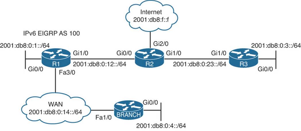
Figure 14-8 EIGRP for IPv6 Trouble Tickets Topology
Trouble Ticket 14-4
Problem: Users in the Branch network of 2001:db8:0:4::/64 have indicated that they are not able to access the Internet.
To verify the problem, you ping 2001:db8:f::f with a source address of 2001:db8:0:4::4, as shown in Example 14-84. The ping fails.
Example 14-84 Verifying the Issue Using an Extended IPv6 Ping
Branch#ping
Protocol [ip]: ipv6
Target IPv6 address: 2001:db8:f::f
Repeat count [5]:
Datagram size [100]:
Timeout in seconds [2]:
Extended commands? [no]: y
Source address or interface: 2001:db8:0:4::4
UDP protocol? [no]:
Verbose? [no]:
Precedence [0]:
DSCP [0]:
Include hop by hop option? [no]:
Include destination option? [no]:
Sweep range of sizes? [no]:
Type escape sequence to abort.
Sending 5, 100-byte ICMP Echos to 2001:DB8:F::F, timeout is 2 seconds:
Packet sent with a source address of 2001:DB8:0:4::4
.....
Success rate is 0 percent (0/5)
Next you issue the show ipv6 route 2001:db8:f::f command on Branch to determine whether there is a route in the IPv6 routing table to reach the address. In Example 14-85, the route is not found.
Example 14-85 Verifying the Route to 2001:db8:f::f in the IPv6 Routing Table on Branch
Branch#show ipv6 route 2001:db8:f::f
% Route not found
Next you visit R1 to determine whether R1 has a route to reach 2001:db8:f::f by using the command show ipv6 route 2001:db8:f::f. In Example 14-86, you can see that the Internet address is reachable via a default route (::/0) that was learned via EIGRP.
Example 14-86 Verifying the Route to 2001:db8:f::f in the IPv6 Routing Table on R1
R1#show ipv6 route 2001:db8:f::f
Routing entry for ::/0
Known via "eigrp 100", distance 170, metric 2816, type external
Route count is 1/1, share count 0
Routing paths:
FE80::C821:17FF:FE04:8, GigabitEthernet1/0
Last updated 00:08:28 ago
You conclude from this that Branch is not learning the default route from R1, which would be used to reach the Internet. You believe that it might be due to a neighbor relationship issue. Back on Branch, you issue the show ipv6 eigrp neighbors command, as shown in Example 14-87, and the output indicates that there is a neighbor relationship with a device out Fa1/0 that has the link-local address FE80::C820:17FF:FE04:54. You are pretty sure that is R1’s link-local address on Fa3/0, but just to be sure, you issue the show ipv6 interface brief command on R1, as shown inExample 14-88. The link-local address from Example 14-87 matches the address in Example 14-88.
Example 14-87 Verifying EIGRP for IPv6 Neighbor Adjacencies
Branch#show ipv6 eigrp neighbors
EIGRP-IPv6 Neighbors for AS(100)
H Address Interface Hold Uptime SRTT RTO Q Seq
(sec) (ms) Cnt Num
0 Link-local address: Fa1/0 12 00:16:01 63 378 0 16
FE80::C820:17FF:FE04:54
Example 14-88 Verifying an IPv6 Link-Local Address
R1#show ipv6 interface brief fastEthernet 3/0
FastEthernet3/0 [up/up]
FE80::C820:17FF:FE04:54
2001:DB8:0:14::1
You decide to check the EIGRP for IPv6 topology table on Branch to see whether it is learning any IPv6 routes from R1. As shown in Example 14-89, Branch is learning routes from R1. It has learned 2001:DB8:0:1::/64, and 2001:DB8:0:12::/64. You are quick to realize that those are only the connected routes on R1. You visit R1 again and issue the show ipv6 eigrp topology command and notice that R1 knows about other IPv6 routes, as shown in Example 14-90. However, it is not advertising them to Branch, as shown in Example 14-89.
Example 14-89 Verifying Learned IPv6 Routes on Branch
Branch#show ipv6 eigrp topology
EIGRP-IPv6 Topology Table for AS(100)/ID(4.4.4.4)
Codes: P - Passive, A - Active, U - Update, Q - Query, R - Reply,
r - reply Status, s - sia Status
P 2001:DB8:0:4::/64, 1 successors, FD is 2816
via Connected, GigabitEthernet0/0
P 2001:DB8:0:1::/64, 1 successors, FD is 28416
via FE80::C820:17FF:FE04:54 (28416/2816), FastEthernet1/0
P 2001:DB8:0:14::/64, 1 successors, FD is 28160
via Connected, FastEthernet1/0
P 2001:DB8:0:12::/64, 1 successors, FD is 28416
via FE80::C820:17FF:FE04:54 (28416/2816), FastEthernet1/0
Example 14-90 Verifying Learned IPv6 Routes on R1
R1#show ipv6 eigrp topology
EIGRP-IPv6 Topology Table for AS(100)/ID(10.1.12.1)
Codes: P - Passive, A - Active, U - Update, Q - Query, R - Reply,
r - reply Status, s - sia Status
P 2001:DB8:0:4::/64, 1 successors, FD is 28416
via FE80::C828:DFF:FEF4:1C (28416/2816), FastEthernet3/0
P 2001:DB8:0:1::/64, 1 successors, FD is 2816
via Connected, GigabitEthernet0/0
P 2001:DB8:0:3::/64, 1 successors, FD is 3328
via FE80::C821:17FF:FE04:8 (3328/3072), GigabitEthernet1/0
P ::/0, 1 successors, FD is 2816
via FE80::C821:17FF:FE04:8 (2816/256), GigabitEthernet1/0
P 2001:DB8:0:14::/64, 1 successors, FD is 28160
via Connected, FastEthernet3/0
P 2001:DB8:0:12::/64, 1 successors, FD is 2816
via Connected, GigabitEthernet1/0
P 2001:DB8:0:23::/64, 1 successors, FD is 3072
via FE80::C821:17FF:FE04:8 (3072/2816), GigabitEthernet1/0
You believe that a route filter is applied. Back on Branch, you issue the command show run | section ipv6 router eigrp, and as shown in Example 14-91, there is no distribute list (route filter) applied. You jump back to R1 and issue the same show command, as shown in Example 14-92, and there is no distribute list (route filter) applied either.
Example 14-91 Verifying Route Filters on Branch
Branch#show run | section ipv6 router eigrp
ipv6 router eigrp 100
eigrp router-id 4.4.4.4
Example 14-92 Verifying Route Filters on R1
R1#show run | section ipv6 router eigrp
ipv6 router eigrp 100
passive-interface default
no passive-interface GigabitEthernet1/0
no passive-interface FastEthernet3/0
eigrp stub connected summary
However, you notice in the output of Example 14-92 that R1 is configured as an EIGRP stub router that is advertising only connected and summary routes. This is the problem. The wrong router was configured as a stub router. The spoke (Branch) is supposed to be the stub router, not the hub (R1) in HQ. To solve this issue, you remove the stub configuration on R1 with the no eigrp stub command in IPv6 router EIGRP 100 configuration mode. You then issue the command eigrp stub on Branch in IPv6 router EIGRP 100 configuration mode.
To verify the problem is solved, you issue the show ipv6 route 2001:db8:f::f command on Branch to determine whether there is an entry in the routing table now. In Example 14-93, the output shows that the default route will be used.
Example 14-93 Verifying the Route to 2001:db8:f::f in the IPv6 Routing Table on Branch
Branch#show ipv6 route 2001:db8:f::f
Routing entry for ::/0
Known via "eigrp 100", distance 170, metric 28416, type external
Route count is 1/1, share count 0
Routing paths:
FE80::C820:17FF:FE04:54, FastEthernet1/0
Last updated 00:03:09 ago
Next you issue the extended IPv6 ping, as shown in Example 14-94, and it is successful.
Example 14-94 Verifying the Issue Is Solved Using an Extended IPv6 Ping
Branch#ping
Protocol [ip]: ipv6
Target IPv6 address: 2001:db8:f::f
Repeat count [5]:
Datagram size [100]:
Timeout in seconds [2]:
Extended commands? [no]: y
Source address or interface: 2001:db8:0:4::4
UDP protocol? [no]:
Verbose? [no]:
Precedence [0]:
DSCP [0]:
Include hop by hop option? [no]:
Include destination option? [no]:
Sweep range of sizes? [no]:
Type escape sequence to abort.
Sending 5, 100-byte ICMP Echos to 2001:DB8:F::F, timeout is 2 seconds:
Packet sent with a source address of 2001:DB8:0:4::4
!!!!!
Success rate is 100 percent (5/5)
Troubleshooting Named EIGRP Configurations
The purpose of EIGRP named configurations is to provide you with a central location on the local router to perform all EIGRP for IPv4 and IPv6 configurations. Example 14-95 provides a sample named EIGRP configuration called TSHOOT_EIGRP. This named EIGRP configuration includes an IPv4 unicast address family and an IPv6 unicast address family. They are both using autonomous system 100; however, that is not mandatory.
Example 14-95 Sample Named EIGRP Configuration
Branch#show run | section router eigrp
router eigrp TSHOOT_EIGRP
!
address-family ipv4 unicast autonomous-system 100
!
af-interface default
passive-interface
exit-af-interface
!
af-interface FastEthernet1/0
no passive-interface
exit-af-interface
!
topology base
exit-af-topology
network 10.1.4.4 0.0.0.0
network 10.1.14.4 0.0.0.0
eigrp router-id 4.4.4.4
eigrp stub connected summary
exit-address-family
!
address-family ipv6 unicast autonomous-system 100
!
af-interface default
passive-interface
exit-af-interface
!
af-interface FastEthernet1/0
no passive-interface
exit-af-interface
!
topology base
maximum-paths 2
variance 3
exit-af-topology
eigrp router-id 44.44.44.44
eigrp stub connected summary
exit-address-family
Because the configuration is the only thing that is different, all the issues already discussed thus far for EIGRP for IPv4 and EIGRP for IPv6 will apply here. However, now you need to know which show commands will help you successfully troubleshoot named EIGRP deployments.
In this section, you learn the show commands that you can use to troubleshoot named EIGRP configurations.
Named EIGRP Verification Commands
With named EIGRP, you can use all the same EIGRP show commands that you used for classic EIGRP for IPv4 and classic EIGRP for IPv6 that were covered in this chapter. However, there is also a new set of show commands for named EIGRP that you may want to learn.
The command show eigrp protocols will display both the EIGRP for IPv4 address family and the EIGRP for IPv6 address family along with the autonomous system number associated with each. It also displays the K values, the router ID, whether the router is a stub router, the AD, the maximum paths, and the variance.
Example 14-96 Output of show eigrp protocols
Branch#show eigrp protocols
EIGRP-IPv4 VR(TSHOOT_EIGRP) Address-Family Protocol for AS(100)
Metric weight K1=1, K2=0, K3=1, K4=0, K5=0 K6=0
Metric rib-scale 128
Metric version 64bit
NSF-aware route hold timer is 240
Router-ID: 4.4.4.4
Stub, connected, summary
Topology : 0 (base)
Active Timer: 3 min
Distance: internal 90 external 170
Maximum path: 4
Maximum hopcount 100
Maximum metric variance 1
Total Prefix Count: 5
Total Redist Count: 0
EIGRP-IPv6 VR(TSHOOT_EIGRP) Address-Family Protocol for AS(100)
Metric weight K1=1, K2=0, K3=1, K4=0, K5=0 K6=0
Metric rib-scale 128
Metric version 64bit
NSF-aware route hold timer is 240
Router-ID: 44.44.44.44
Stub, connected, summary
Topology : 0 (base)
Active Timer: 3 min
Distance: internal 90 external 170
Maximum path: 2
Maximum hopcount 100
Maximum metric variance 3
Total Prefix Count: 7
Total Redist Count: 0
This is similar to the show ip protocols and show ipv6 protocols output. However, it is missing the interfaces that are participating in the routing process, along with the passive interfaces. Therefore, show ip protocols and show ipv6 protocols at this time are a preferred option.
To verify the interfaces that are participating in the routing process for each address family, you can issue the show eigrp address-family ipv4 interfaces command and the show eigrp address-family ipv6 interfaces command, as shown in Example 14-97. Make note that passive interfaces do not show up in this output. Based on the classic show ip protocols and show ipv6 protocols commands, we would be able to verify the passive interfaces.
Example 14-97 Verifying Interfaces Participating in the Named EIGRP Process
Branch#show eigrp address-family ipv4 interfaces
EIGRP-IPv4 VR(TSHOOT_EIGRP) Address-Family Interfaces for AS(100)
Xmit Queue PeerQ Mean Pacing Time Multicast Pending
Interface Peers Un/Reliable Un/Reliable SRTT Un/Reliable Flow Timer Routes
Fa1/0 1 0/0 0/0 88 0/0 50 0
Branch#show eigrp address-family ipv6 interfaces
EIGRP-IPv6 VR(TSHOOT_EIGRP) Address-Family Interfaces for AS(100)
Xmit Queue PeerQ Mean Pacing Time Multicast Pending
Interface Peers Un/Reliable Un/Reliable SRTT Un/Reliable Flow Timer Routes
Fa1/0 1 0/0 0/0 73 0/1 304 0
As shown in Example 14-98, when you add the detail keyword to the show eigrp address-family ipv4 interfaces command and the show eigrp address-family ipv6 interfaces command, you can verify additional interface parameters (for example, hello interval and hold time, whether split-horizon is enabled, whether authentication is set, and statistics about hellos and packets).
Example 14-98 Verifying Details of Interfaces Participating in the Named EIGRP Process
Branch#show eigrp address-family ipv4 interfaces detail
EIGRP-IPv4 VR(TSHOOT_EIGRP) Address-Family Interfaces for AS(100)
Xmit Queue PeerQ Mean Pacing Time Multicast Pending
Interface Peers Un/Reliable Un/Reliable SRTT Un/Reliable Flow Timer Routes
Fa1/0 1 0/0 0/0 88 0/0 50 0
Hello-interval is 5, Hold-time is 15
Split-horizon is enabled
Next xmit serial <none>
Packetized sent/expedited: 1/0
Hello's sent/expedited: 333/2
Un/reliable mcasts: 0/1 Un/reliable ucasts: 2/2
Mcast exceptions: 0 CR packets: 0 ACKs suppressed: 0
Retransmissions sent: 1 Out-of-sequence rcvd: 1
Topology-ids on interface - 0
Authentication mode is not set
Branch#show eigrp address-family ipv6 interfaces detail
EIGRP-IPv6 VR(TSHOOT_EIGRP) Address-Family Interfaces for AS(100)
Xmit Queue PeerQ Mean Pacing Time Multicast Pending
Interface Peers Un/Reliable Un/Reliable SRTT Un/Reliable Flow Timer Routes
Fa1/0 1 0/0 0/0 73 0/1 304 0
Hello-interval is 5, Hold-time is 15
Split-horizon is enabled
Next xmit serial <none>
Packetized sent/expedited: 3/0
Hello's sent/expedited: 595/3
Un/reliable mcasts: 0/2 Un/reliable ucasts: 5/3
Mcast exceptions: 0 CR packets: 0 ACKs suppressed: 0
Retransmissions sent: 1 Out-of-sequence rcvd: 2
Topology-ids on interface - 0
Authentication mode is not set
You can verify neighbors with the show eigrp address-family ipv4 neighbors and show eigrp address-family ipv6 neighbors commands, as shown in Example 14-99. Just like we saw with the classic commands, if you want to verify whether the neighbor is a stub router, you can add thedetail keyword to the commands.
Example 14-99 Verifying Named EIGRP Neighbors
Branch#show eigrp address-family ipv4 neighbors
EIGRP-IPv4 VR(TSHOOT_EIGRP) Address-Family Neighbors for AS(100)
H Address Interface Hold Uptime SRTT RTO Q Seq
(sec) (ms) Cnt Num
0 10.1.14.1 Fa1/0 14 00:31:08 88 528 0 8
Branch#show eigrp address-family ipv6 neighbors
EIGRP-IPv6 VR(TSHOOT_EIGRP) Address-Family Neighbors for AS(100)
H Address Interface Hold Uptime SRTT RTO Q Seq
(sec) (ms) Cnt Num
0 Link-local address: Fa1/0 14 00:50:33 73 438 0 40
FE80::C820:17FF:FE04:54
To display the topology table, you can use the commands show eigrp address-family ipv4 topology and show eigrp address-family ipv6 topology, as shown in Example 14-100
Example 14-100 Verifying Named EIGRP Topology Tables
Branch#show eigrp address-family ipv4 topology
EIGRP-IPv4 VR(TSHOOT_EIGRP) Topology Table for AS(100)/ID(4.4.4.4)
Codes: P - Passive, A - Active, U - Update, Q - Query, R - Reply,
r - reply Status, s - sia Status
P 10.1.12.0/24, 1 successors, FD is 13762560
via 10.1.14.1 (13762560/1310720), FastEthernet1/0
P 10.1.14.0/24, 1 successors, FD is 13107200
via Connected, FastEthernet1/0
P 10.1.3.0/24, 1 successors, FD is 15073280
via 10.1.14.1 (15073280/2621440), FastEthernet1/0
P 10.1.23.0/24, 1 successors, FD is 14417920
via 10.1.14.1 (14417920/1966080), FastEthernet1/0
P 10.1.4.0/24, 1 successors, FD is 1310720
via Connected, GigabitEthernet0/0
P 10.1.1.0/24, 1 successors, FD is 13762560
via 10.1.14.1 (13762560/1310720), FastEthernet1/0
Branch#show eigrp address-family ipv6 topology
EIGRP-IPv6 VR(TSHOOT_EIGRP) Topology Table for AS(100)/ID(44.44.44.44)
Codes: P - Passive, A - Active, U - Update, Q - Query, R - Reply,
r - reply Status, s - sia Status
P 2001:DB8:0:4::/64, 1 successors, FD is 1310720
via Connected, GigabitEthernet0/0
P 2001:DB8:0:1::/64, 1 successors, FD is 13762560
via FE80::C820:17FF:FE04:54 (13762560/1310720), FastEthernet1/0
P 2001:DB8:0:3::/64, 1 successors, FD is 15073280
via FE80::C820:17FF:FE04:54 (15073280/2621440), FastEthernet1/0
P ::/0, 1 successors, FD is 13762560
via FE80::C820:17FF:FE04:54 (13762560/1310720), FastEthernet1/0
P 2001:DB8:0:14::/64, 1 successors, FD is 13107200
via Connected, FastEthernet1/0
P 2001:DB8:0:12::/64, 1 successors, FD is 13762560
via FE80::C820:17FF:FE04:54 (13762560/1310720), FastEthernet1/0
P 2001:DB8:0:23::/64, 1 successors, FD is 14417920
via FE80::C820:17FF:FE04:54 (14417920/1966080), FastEthernet1/0
Named EIGRP Trouble Tickets
This section presents various trouble tickets relating to the topics discussed earlier in the chapter. The purpose of these trouble tickets is to give a process that you can follow when troubleshooting in the real world or in an exam environment. All trouble tickets in this section are based on the topology depicted in Figure 14-9.
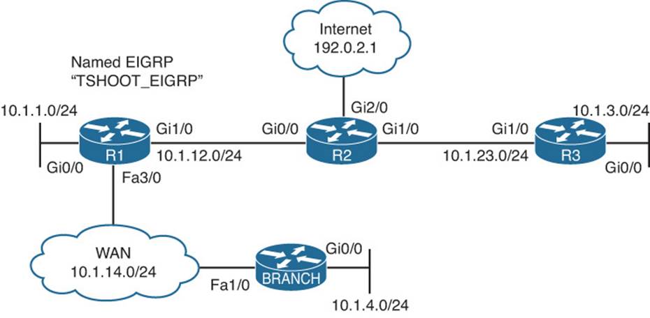
Figure 14-9 Named EIGRP Trouble Tickets Topology
Trouble Ticket 14-5
Problem: Users in the 10.1.4.0/24 network indicate that they are not able to access resources outside of their LAN.
On Branch, you verify the problem by pinging a few different IP addresses and source the packets from 10.1.4.4. As shown in Example 14-101, they all fail.
Example 14-101 Verifying the Problem
Branch#ping 10.1.3.3 source 10.1.4.4
Type escape sequence to abort.
Sending 5, 100-byte ICMP Echos to 10.1.3.3, timeout is 2 seconds:
Packet sent with a source address of 10.1.4.4
.....
Success rate is 0 percent (0/5)
Branch#ping 192.0.2.1 source 10.1.4.4
Type escape sequence to abort.
Sending 5, 100-byte ICMP Echos to 192.0.2.1, timeout is 2 seconds:
Packet sent with a source address of 10.1.4.4
.....
Success rate is 0 percent (0/5)
Branch#ping 10.1.1.1 source 10.1.4.4
Type escape sequence to abort.
Sending 5, 100-byte ICMP Echos to 10.1.1.1, timeout is 2 seconds:
Packet sent with a source address of 10.1.4.4
.....
Success rate is 0 percent (0/5)
Next you issue the show ip route command to verify whether any routes are installed in the routing table. As shown in Example 14-102, only local and directly connected routes are in the routing table.
Example 14-102 Displaying the IPv4 Routing Table on Branch
Branch#show ip route
...output omitted...
Gateway of last resort is not set
10.0.0.0/8 is variably subnetted, 4 subnets, 2 masks
C 10.1.4.0/24 is directly connected, GigabitEthernet0/0
L 10.1.4.4/32 is directly connected, GigabitEthernet0/0
C 10.1.14.0/24 is directly connected, FastEthernet1/0
L 10.1.14.4/32 is directly connected, FastEthernet1/0
You hypothesize that Branch is not a neighbor with R1 across the WAN. You issue the show eigrp address-family ipv4 neighbors command, as shown in Example 14-103, and confirm that R1 is not a neighbor.
Example 14-103 Displaying the Named EIGRP IPv4 Neighbor Table
Branch#show eigrp address-family ipv4 neighbors
EIGRP-IPv4 VR(TSHOOT_EIGRP) Address-Family Neighbors for AS(100)
Next you hypothesize that Fast Ethernet 1/0 (the interface that will form an adjacency with R1) is not participating in the named EIGRP process. You issue the command show eigrp address-family ipv4 interfaces, as shown in Example 14-104, and confirm your hypothesis.
Example 14-104 Displaying the Named EIGRP IPv4 Interface Table
Branch#show eigrp address-family ipv4 interfaces
EIGRP-IPv4 VR(TSHOOT_EIGRP) Address-Family Interfaces for AS(100)
Xmit Queue PeerQ Mean Pacing Time Multicast Pending
Interface Peers Un/Reliable Un/Reliable SRTT Un/Reliable Flow Timer Routes
Gi0/0 0 0/0 0/0 0 0/0 0 0
As shown in Example 14-105, the output of show ip interface brief indicates that Fast Ethernet 1/0 has an IPv4 address of 10.1.14.4. Therefore, a network statement is needed that will enable the EIGRP process on that interface.
Example 14-105 Displaying the IPv4 Addresses of Interfaces
Branch#show ip interface brief
Interface IP-Address OK? Method Status Protocol
Ethernet0/0 unassigned YES unset administratively down down
GigabitEthernet0/0 10.1.4.4 YES manual up up
FastEthernet1/0 10.1.14.4 YES manual up up
Armed with the information you have, you issue the show run | section router eigrp command on Branch to confirm that the network statement is missing. In Example 14-106, you see that there is a valid network statement for 10.1.14.4. It is network 10.1.14.4 0.0.0.0 and would successfully enable the EIGRP process on the interface. Therefore, your hypothesis was incorrect.
Example 14-106 Reviewing Named EIGRP Configuration in the Running Configuration
Branch#show running-config | section router eigrp
router eigrp TSHOOT_EIGRP
!
address-family ipv4 unicast autonomous-system 100
!
af-interface default
passive-interface
exit-af-interface
!
af-interface GigabitEthernet0/0
no passive-interface
exit-af-interface
!
topology base
exit-af-topology
network 10.1.4.4 0.0.0.0
network 10.1.14.4 0.0.0.0
eigrp router-id 4.4.4.4
eigrp stub connected summary
exit-address-family
!
address-family ipv6 unicast autonomous-system 100
!
af-interface default
passive-interface
exit-af-interface
!
af-interface FastEthernet1/0
no passive-interface
exit-af-interface
!
topology base
maximum-paths 2
variance 3
exit-af-topology
eigrp router-id 44.44.44.44
eigrp stub connected summary
exit-address-family
What could cause a neighbor relationship not to form? You list a few: authentication, passive interface, wrong subnet.
In Example 14-106, you notice that there are no authentication configurations. However, you do spot a passive interface command on Gig0/0. It is the no passive-interface command. You also notice that af-interface default has the passive-interface command and recall that all interfaces inherit configs under af-interface default. You also recall that they can be overridden with commands at the interface level. Reviewing the topology in Figure 14-9, you come to the conclusion that the wrong interface was configured with the no passive-interface command. It should have been Fast Ethernet 1/0 and not Gig0/0.
Example 14-107 presents the commands that you can use to fix this issue. Notice that once the issue is fixed, the neighbor relationship is formed with R1 at 10.1.14.1.
Example 14-107 Modifying the Named EIGRP Configuration
Branch#config t
Enter configuration commands, one per line. End with CNTL/Z.
Branch(config)#router eigrp TSHOOT_EIGRP
Branch(config-router)#address-family ipv4 unicast autonomous-system 100
Branch(config-router-af)#af-interface GigabitEthernet0/0
Branch(config-router-af-interface)#passive-interface
Branch(config-router-af-interface)#exit
Branch(config-router-af)#af-interface fastEthernet1/0
Branch(config-router-af-interface)#no passive-interface
%DUAL-5-NBRCHANGE: EIGRP-IPv4 100: Neighbor 10.1.14.1 (FastEthernet1/0) is up: new
adjacency
Branch(config-router-af-interface)#end
Branch#
You then review the IPv4 routing table as shown in Example 14-108 and notice all the EIGRP-learned routes.
Example 14-108 Verifying the EIGRP-Learned Routes
Branch#show ip route
...output omitted...
Gateway of last resort is 10.1.14.1 to network 0.0.0.0
D*EX 0.0.0.0/0 [170/112640] via 10.1.14.1, 00:00:34, FastEthernet1/0
10.0.0.0/8 is variably subnetted, 8 subnets, 2 masks
D 10.1.1.0/24 [90/107520] via 10.1.14.1, 00:05:53, FastEthernet1/0
D 10.1.3.0/24 [90/117760] via 10.1.14.1, 00:05:53, FastEthernet1/0
C 10.1.4.0/24 is directly connected, GigabitEthernet0/0
L 10.1.4.4/32 is directly connected, GigabitEthernet0/0
D 10.1.12.0/24 [90/107520] via 10.1.14.1, 00:05:53, FastEthernet1/0
C 10.1.14.0/24 is directly connected, FastEthernet1/0
L 10.1.14.4/32 is directly connected, FastEthernet1/0
D 10.1.23.0/24 [90/112640] via 10.1.14.1, 00:05:53, FastEthernet1/0
Next you reissue the same pings that were used to confirm the problem. In Example 14-109, they are successful.
Example 14-109 Successful Pings from Branch to Various Network IPs
Branch#ping 10.1.1.1 source 10.1.4.4
Type escape sequence to abort.
Sending 5, 100-byte ICMP Echos to 10.1.1.1, timeout is 2 seconds:
Packet sent with a source address of 10.1.4.4
!!!!!
Success rate is 100 percent (5/5), round-trip min/avg/max = 44/55/72 ms
Branch#ping 10.1.3.3 source 10.1.4.4
Type escape sequence to abort.
Sending 5, 100-byte ICMP Echos to 10.1.3.3, timeout is 2 seconds:
Packet sent with a source address of 10.1.4.4
!!!!!
Success rate is 100 percent (5/5), round-trip min/avg/max = 52/79/92 ms
Branch#ping 192.0.2.1 source 10.1.4.4
Type escape sequence to abort.
Sending 5, 100-byte ICMP Echos to 192.0.2.1, timeout is 2 seconds:
Packet sent with a source address of 10.1.4.4
!!!!!
Success rate is 100 percent (5/5), round-trip min/avg/max = 76/84/92 ms
Exam Preparation Tasks
As mentioned in the section “How to Use This Book” in the Introduction, you have a couple of choices for exam preparation: the exercises here; Chapter 22, “Final Preparation;” and the exam simulation questions on the CD-ROM.
Review All Key Topics
Review the most important topics in this chapter, noted with the Key Topic icon in the outer margin of the page. Table 14-2 lists a reference of these key topics and the page numbers on which each is found.
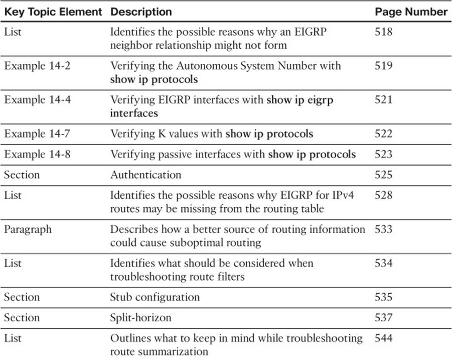
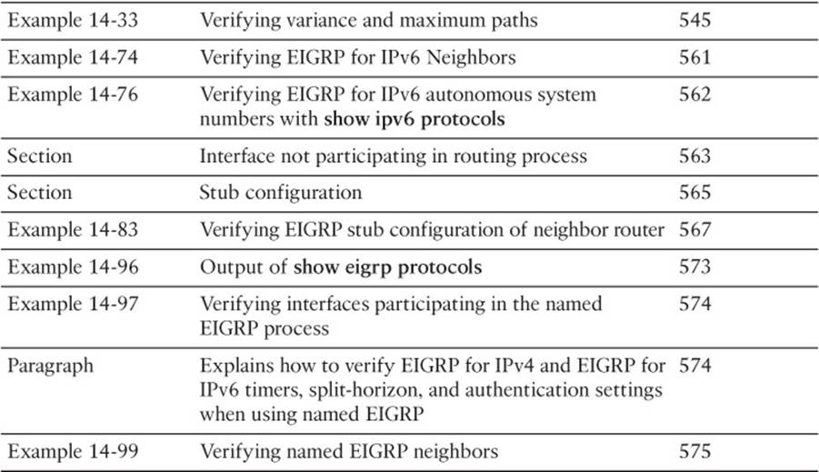
Table 14-2 Key Topics for Chapter 14
Define Key Terms
Define the following key terms from this chapter and check your answers in the glossary:
hello packet
224.0.0.10
network command
autonomous system number
K values
passive interface
key ID
key string
key chain
stub
split-horizon
successor
feasible successor
reported distance
feasible distance
discontiguous network
autosummarization
classful
classless
maximum paths
variance
named EIGRP
address family
Command Reference to Check Your Memory
This section includes the most important show and debug commands covered in this chapter. It might not be necessary to memorize the complete syntax of every command, but you should be able to remember the basic keywords that are needed.
To test your memory of the commands, cover the right side of Table 14-3 with a piece of paper, read the description on the left side, and then see how much of the command you can remember.
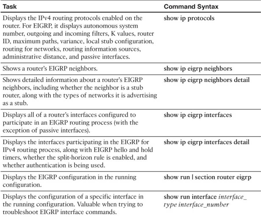
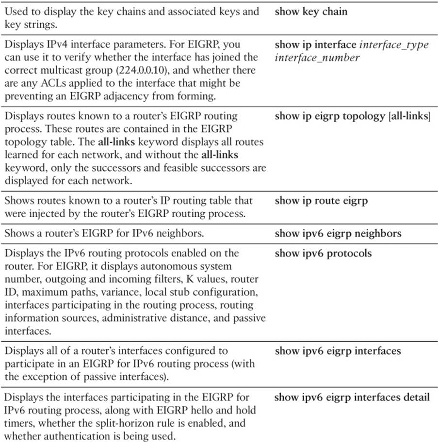
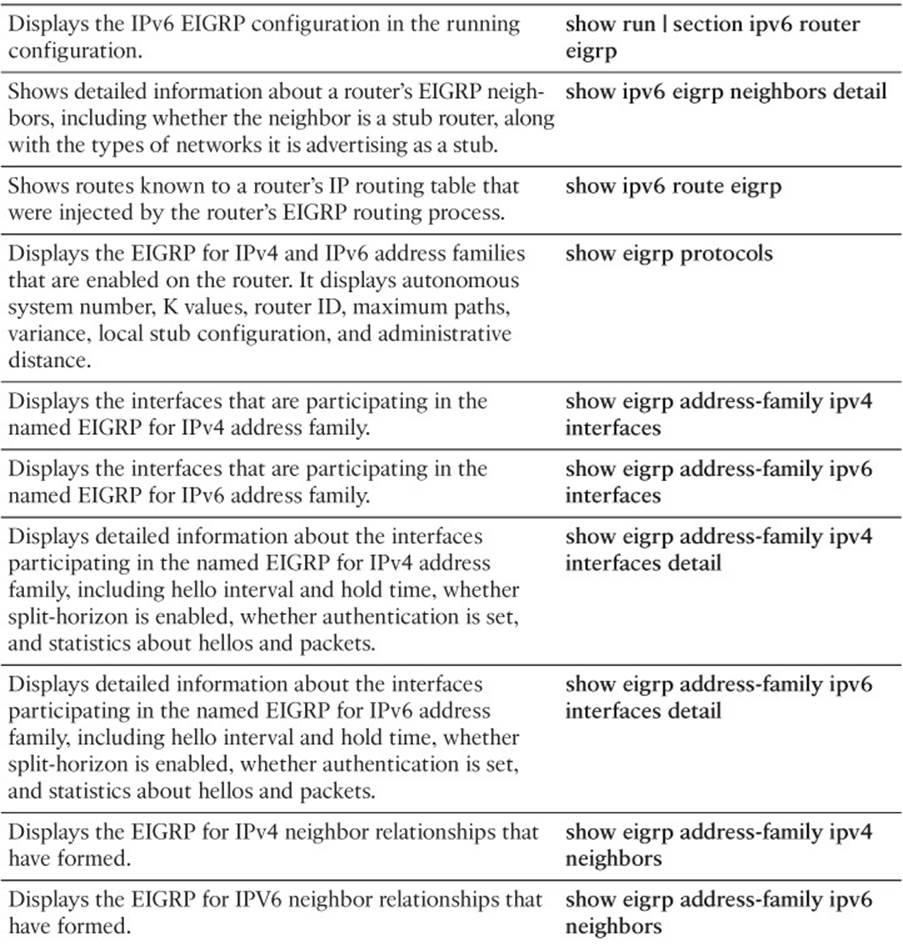
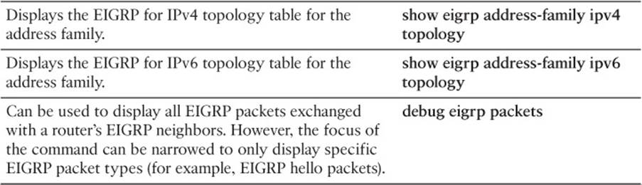
Table 14-3 EIGRP show and debug Commands
The 300-135 TSHOOT exam focuses on practical, hands-on skills that are used by a networking professional. Therefore, you should be able to identify the commands needed to successfully identify and troubleshoot the issues presented in this chapter.
All materials on the site are licensed Creative Commons Attribution-Sharealike 3.0 Unported CC BY-SA 3.0 & GNU Free Documentation License (GFDL)
If you are the copyright holder of any material contained on our site and intend to remove it, please contact our site administrator for approval.
© 2016-2026 All site design rights belong to S.Y.A.