CCNP Routing and Switching TSHOOT 300-135 Official Cert Guide (2015)
Part III. Troubleshooting Router Features
Chapter 15. Troubleshooting OSPF
This chapter covers the following topics:
![]() Troubleshooting OSPFv2: This section covers the reasons why OSPFv2 neighbor relationships are not being formed and how you can identify them. In addition, you will learn the reasons why OSPFv2 routes might be missing and how to determine why they are missing.
Troubleshooting OSPFv2: This section covers the reasons why OSPFv2 neighbor relationships are not being formed and how you can identify them. In addition, you will learn the reasons why OSPFv2 routes might be missing and how to determine why they are missing.
![]() OSPFv2 Trouble Tickets: This section provides trouble tickets that demonstrate how you can use a structured troubleshooting process to solve a reported problem.
OSPFv2 Trouble Tickets: This section provides trouble tickets that demonstrate how you can use a structured troubleshooting process to solve a reported problem.
![]() Troubleshooting OSPFv3 for IPv6: In this section, you examine the different commands that you can use to troubleshoot OSPFv3 issues.
Troubleshooting OSPFv3 for IPv6: In this section, you examine the different commands that you can use to troubleshoot OSPFv3 issues.
![]() OSPFv3 Trouble Tickets: This section provides trouble tickets that demonstrate how you can use a structured troubleshooting process to solve a reported problem.
OSPFv3 Trouble Tickets: This section provides trouble tickets that demonstrate how you can use a structured troubleshooting process to solve a reported problem.
![]() Troubleshooting OSPFv3 Address Families: In this section, you discover the commands that you can use to troubleshoot issues related to OSPFv3 address family configurations.
Troubleshooting OSPFv3 Address Families: In this section, you discover the commands that you can use to troubleshoot issues related to OSPFv3 address family configurations.
![]() OSPFv3 Address Family Trouble Tickets: This section provides trouble tickets that demonstrate how you can use a structured troubleshooting process to solve a reported problem.
OSPFv3 Address Family Trouble Tickets: This section provides trouble tickets that demonstrate how you can use a structured troubleshooting process to solve a reported problem.
The Open Shortest Path First (OSPF) dynamic routing protocol is a link-state routing protocol that uses Dijkstra’s shortest path first (SPF) algorithm. It is an extremely scalable routing protocol because of its hierarchical design implementation. OSPF can route for both IPv4 and IPv6 protocols. This chapter focuses on troubleshooting both OSPFv2 and OSPFv3 using the classic configurations and the newer OSPF address family configurations.
Before any routes can be exchanged between OSPF routers on the same LAN or across a WAN, an OSPF neighbor relationship has to be formed. There are many reasons why a neighbor relationship will not form, and as a troubleshooter, you need to be aware of them. This chapter delves deeply into these reasons and gives you the tools needed to identify them and successfully solve neighbor issues.
Once neighbor relationships are formed, neighboring routers will exchange OSPF LSAs, which contain information about routes. In various cases, routes may end up missing, and you need to be able to determine why the routes are missing. This chapter discusses the various ways that OSPF routes could go missing, how you can identify the reasons why they are missing, and how you can solve route-related issues.
In this chapter, you will also learn how to troubleshoot issues related to load balancing, summarization, and discontiguous areas.
“Do I Know This Already?” Quiz
The “Do I Know This Already?” quiz allows you to assess whether you should read this entire chapter thoroughly or jump to the “Exam Preparation Tasks” section. If you are in doubt about your answers to these questions or your own assessment of your knowledge of the topics, read the entire chapter. Table 15-1 lists the major headings in this chapter and their corresponding “Do I Know This Already?” quiz questions. You can find the answers in Appendix A, “Answers to the ‘Do I Know This Already?’ Quizzes.”
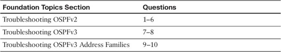
Table 15-1 “Do I Know This Already?” Section-to-Question Mapping
Caution
The goal of self-assessment is to gauge your mastery of the topics in this chapter. If you do not know the answer to a question or are only partially sure of the answer, you should mark that question as wrong for purposes of the self-assessment. Giving yourself credit for an answer that you correctly guess skews your self-assessment results and might provide you with a false sense of security.
1. Which three of the following are reasons why an OSPF neighbor relationship will not form?
a. Mismatched timers
b. Mismatched area numbers
c. Duplicate router IDs
d. Wrong designated router was elected
2. In which two OSPF states are you likely to find routers that have an MTU mismatch?
a. Init
b. 2Way
c. Exstart
d. Exchange
3. Which OSPFv2 command enables you to verify the hello interval and the dead interval?
a. show ip protocols
b. show ip ospf interface
c. show ip ospf neighbor
d. show ip ospf database
4. Which OSPFv2 debug command enables you to verify whether area numbers are mismatched?
a. debug ip ospf hello
b. debug ip ospf adj
c. debug ip ospf packet
d. debug ip ospf events
5. Which OSPF network type is the default on LAN interfaces?
a. Broadcast
b. NBMA
c. Point to point
d. Point to multipoint
6. Which LSA type describes routes outside the area but still within the OSPF routing domain (interarea routes)?
a. 1
b. 2
c. 3
d. 5
7. Which IPv6 OSPFv3 command enables you to verify whether an area is a stub, totally stubby, NSSA, or totally NSSA area?
a. show ipv6 protocols
b. show ipv6 ospf
c. show ipv6 ospf interface
d. show ipv6 ospf neighbor
8. Which IPv6 OSPFv3 command enables you to verify which routers the local router has formed neighbor adjacencies with?
a. show ipv6 protocols
b. show ipv6 ospf
c. show ipv6 ospf interface
d. show ipv6 ospf neighbor
9. Which two OSPFv3 address family commands are used to verify which OSPFv3 address family an interface is participating in?
a. show ospfv3
b. show ospfv3 interface brief
c. show ospfv3 neighbors
d. show ospfv3 database
10. Which OSPFv3 address family debug command will identify whether there is a mismatched stub area configuration?
a. debug ospfv3 hello
b. debug ospfv3 packet
c. debug ospfv3 adj
d. debug ospfv3 events
Foundation Topics
Troubleshooting OSPFv2
OSPF establishes neighbor relationships by sending hello packets out interfaces participating in the OSPF process. To enable the OSPF process on an interface and place it in an OSPF area, you use the network ip_address wildcard_mask area area_id command in router OSPF configuration mode or the ip ospf process_id area area_id command in interface configuration mode. For example, the following network area command enables OSPF on all interfaces with an IP address from 10.1.1.0 through 10.1.1.255 and places them in area 0: network 10.1.1.0 0.0.0.255 area 0. The following interface configuration command enables the OSPF process on the interface and places it in area 51: ip ospf 1 area 51. Because there are two different ways to enable OSPFv2 on an interface, you have to be very careful when troubleshooting neighbor adjacencies so that you are not led down the wrong path thinking the OSPF process was not enabled on an interface when in fact it was. This is your warning to check both places.
OSPF routers will receive LSAs from every router within the same area, meaning they learn about routes directly from the source within the same area. As a result, it is necessary that the LSAs are flooded through the area. This is mandatory because every router in an area must have the exact same LSDB for that area. This makes troubleshooting missing OSPF routes more difficult than distance vector routing protocols because it is harder to follow the path, especially in a multi-area OSPF domain.
This section focuses on the reasons why an OSPF neighbor relationship might not form and how we can identify them during the troubleshooting process. In addition, we will examine the reasons why OSPF routes might be missing, and how we can determine the reason why they are missing. To wrap up the section, we will troubleshoot OSPF issues that do not fall into the neighbor relationship or route categories.
Troubleshooting OSPFv2 Neighbor Adjacencies
To verify OSPFv2 neighbors, you use the show ip ospf neighbor command. In Example 15-1, you see a sample output of the show ip ospf neighbor command. It lists the neighbor ID, which is the router ID (RID) of the neighbor, the priority of the neighbor for the designated router / backup designated router (DR/BDR) election process, the state of the neighbor (covered shortly), and whether they are a DR, BDR, or DROther. In addition, it displays the dead time, which is how long the local router will wait until it declares the neighbor down if it does not hear another hello packet within that time (default is 40 seconds on a LAN). You can also see the neighbor’s interface IP address that they sent the hello packet from and the local router interface that is used to reach that neighbor.

Example 15-1 Verifying OSPF Neighbors with show ip ospf neighbor
R1#show ip ospf neighbor
Neighbor ID Pri State Dead Time Address Interface
10.1.23.2 1 FULL/BDR 00:00:37 10.1.12.2 GigabitEthernet1/0
When an OSPF neighbor adjacency is successfully formed you will receive a syslog message similar to the following:
%OSPF-5-ADJCHG: Process 1, Nbr 10.1.23.2 on GigabitEthernet1/0 from LOADING to FULL, Loading Done
Here is a listing of reasons why an OSPFv2 neighbor relationship might not form:
![]() Interface is down: The interface has to be up/up.
Interface is down: The interface has to be up/up.
![]() Interface not running the OSPF process: If the interface is not enabled for OSPF, it will not send hello packets or form an adjacency.
Interface not running the OSPF process: If the interface is not enabled for OSPF, it will not send hello packets or form an adjacency.
![]() Mismatched timers: Hello and dead timers have to match between neighbors.
Mismatched timers: Hello and dead timers have to match between neighbors.
![]() Mismatched area numbers: Both ends of a link must be in the same OSPF area.
Mismatched area numbers: Both ends of a link must be in the same OSPF area.
![]() Mismatched area type: In addition to a normal OSPF area type, an area type could be either stub or not-so-stubby area (NSSA). The routers have to agree on the type of area they are in.
Mismatched area type: In addition to a normal OSPF area type, an area type could be either stub or not-so-stubby area (NSSA). The routers have to agree on the type of area they are in.
![]() Different subnets: Neighbors have to be in the same subnet.
Different subnets: Neighbors have to be in the same subnet.
![]() Passive interface: The passive interface feature suppresses the sending and receiving of hello packets while still allowing the interfaces network to be advertised.
Passive interface: The passive interface feature suppresses the sending and receiving of hello packets while still allowing the interfaces network to be advertised.
![]() Mismatched authentication information: If one OSPF interface is configured for authentication, the OSPF interface at the other end of the link has to be configured with matching authentication information.
Mismatched authentication information: If one OSPF interface is configured for authentication, the OSPF interface at the other end of the link has to be configured with matching authentication information.
![]() ACLs: An ACL that is denying packets to the OSPF multicast address 224.0.0.5.
ACLs: An ACL that is denying packets to the OSPF multicast address 224.0.0.5.
![]() MTU mismatch: The maximum transmission unit of neighboring interfaces must match.
MTU mismatch: The maximum transmission unit of neighboring interfaces must match.
![]() Duplicate router IDs: Router IDs must be unique.
Duplicate router IDs: Router IDs must be unique.
![]() Mismatched network types: Based on the OSPF network type characteristics and default values, two neighbors configured with a different OSPF network type might not form an adjacency.
Mismatched network types: Based on the OSPF network type characteristics and default values, two neighbors configured with a different OSPF network type might not form an adjacency.
Adjacencies are not established upon the immediate receipt of hello messages. Rather, an adjacency transitions through multiple states, as described in Table 15-2.
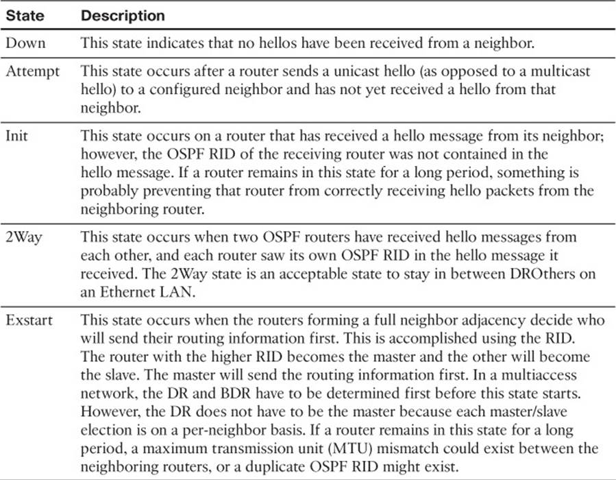
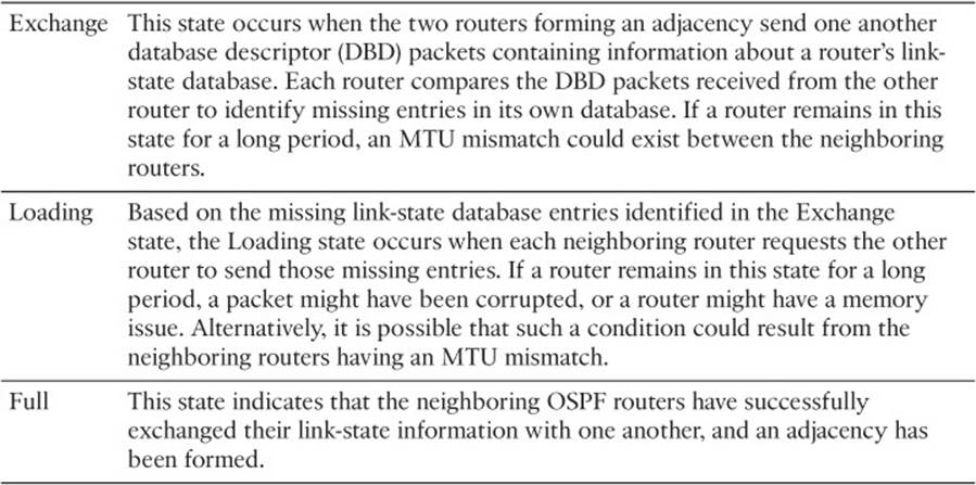
Table 15-2 Adjacency States
When an OSPF neighbor relationship does not form, the neighbor is not listed in the neighbor table. Therefore, you will need the assistance of an accurate network diagram and the show cdp neighbors command to verify who should be the neighbors.
When troubleshooting OSPF adjacencies, you need to be aware of how to verify the parameters associated with each reason we listed earlier. Let’s look at them individually.
Interface Is Down
The interface has to be up if you plan on forming an OSPF neighbor adjacency. As we have seen already, we can verify the status of an interface with the show ip interface brief command.
Interface Not Running the OSPF Process
If the router OSPF configuration mode network ip_address wildcard_mask area area_id command or the ip ospf process_id area area_id interface command is misconfigured, OSPF may not be enabled on the proper interfaces. As a result, hello packets will not be sent and neighbor relationships will not be formed. You also have to specify the OSPF area the interface belongs to. Therefore, if the command is correct, except for the area ID, the interface is participating in the OSPF process but in the wrong area. This will prevent a neighbor relationship from forming as well. You can verify which interfaces are participating in the OSPF process with the command show ip ospf interface brief, as shown in Example 15-2. In this example, two interfaces are participating in OSPF process 1. They are both in area 1 and are the designated router interfaces for the multiaccess networks. You can also verify the IP address and masks of the interfaces along with the number of full neighbor relationships that have been formed out the interface versus the total number of neighbors out the interface.
Note
Remember that OSPF passive interfaces do show up in this output.
Example 15-2 Verifying OSPF Interfaces with show ip ospf interface brief
R1#show ip ospf interface brief
Interface PID Area IP Address/Mask Cost State Nbrs F/C
Gi0/0 1 1 10.1.1.1/24 1 DR 0/0
Gi1/0 1 1 10.1.12.1/24 1 DR 1/1
The output of show ip protocols displays the network ip_address wildcard_mask area area_id statements as well as those interfaces that were enabled for OSPF with the ip ospf process_id area area_id interface command. Focus on the highlighted text in Example 15-3. Notice that it statesRouting for Networks. Those are not the networks we are routing for. We are routing for the networks associated with the interfaces OSPF will be enabled on, based on the network area statement. In this case, 10.1.1.1 0.0.0.0 area 1 really means network 10.1.1.1 0.0.0.0 area 1. Therefore, the interface with this IP address will be enabled for the OSPF process and placed in area 1. In addition, you can see which interfaces were explicitly configured to participate in the OSPF process with the ip ospf process_id area area_id interface configuration mode command. In thisexample, it is Gigabit Ethernet 1/0 that was enabled for OSPF with the ip ospf 1 area 1 command, and Gigabit Ethernet 0/0 was enabled for OSPF with the network 10.1.1.1 0.0.0.0 area 1 router OSPF configuration mode command.
Example 15-3 Verifying OSPF-Enabled Interfaces with show ip protocols
R1#show ip protocols
*** IP Routing is NSF aware ***
Routing Protocol is "ospf 1"
Outgoing update filter list for all interfaces is not set
Incoming update filter list for all interfaces is not set
Router ID 10.1.12.1
Number of areas in this router is 1. 1 normal 0 stub 0 nssa
Maximum path: 4
Routing for Networks:
10.1.1.1 0.0.0.0 area 1
Routing on Interfaces Configured Explicitly (Area 1):
GigabitEthernet1/0
Routing Information Sources:
Gateway Distance Last Update
10.1.23.2 110 00:24:22
Distance: (default is 110)
As you can see, the network area statement is extremely important, as is the ip ospf area command. If either are misconfigured, interfaces that should be participating in the OSPF process might not be, and interfaces that should not be participating in the OSPF process might be. In addition, it is possible that they might be participating but in the wrong area, causing neighbor relationships not to form. Therefore, you should be able to recognize issues related with both these commands.
Note
If an interface is enabled for OSPF with both the network area command and the ip ospf area command, the ip ospf area command takes precedence.
Mismatched Timers
Unlike Enhanced Interior Gateway Routing Protocol (EIGRP), OSPF timers do have to match between neighbors to form a neighbor adjacency. The hello timer defaults to 10 seconds for broadcast and point-to-point network types and 30 seconds for nonbroadcast and point-to-multipoint network types. The dead timer defaults to 40 seconds for broadcast and point-to-point network types and 120 seconds for nonbroadcast and point-to-multipoint network types. To verify the current timers associated with an OSPF interface, issue the show ip ospf interface interface_type interface_number command, as shown in Example 15-4. In this example, Gigabit Ethernet 1/0 is using the default timers of 10 and 40. When determining whether timers match, use the spot-the-difference method between the outputs on both routers.
Example 15-4 Displaying OSPF Interface Timers on R1 Gigabit Ethernet 1/0
R1#show ip ospf interface gigabitEthernet 1/0
GigabitEthernet1/0 is up, line protocol is up
Internet Address 10.1.12.1/24, Area 1, Attached via Interface Enable
Process ID 1, Router ID 10.1.12.1, Network Type BROADCAST, Cost: 1
Topology-MTID Cost Disabled Shutdown Topology Name
0 1 no no Base
Enabled by interface config, including secondary ip addresses
Transmit Delay is 1 sec, State DR, Priority 1
Designated Router (ID) 10.1.12.1, Interface address 10.1.12.1
Backup Designated router (ID) 10.1.23.2, Interface address 10.1.12.2
Timer intervals configured, Hello 10, Dead 40, Wait 40, Retransmit 5
oob-resync timeout 40
Hello due in 00:00:04
Supports Link-local Signaling (LLS)
Cisco NSF helper support enabled
IETF NSF helper support enabled
Index 1/1, flood queue length 0
Next 0x0(0)/0x0(0)
Last flood scan length is 1, maximum is 1
Last flood scan time is 0 msec, maximum is 4 msec
Neighbor Count is 1, Adjacent neighbor count is 1
Adjacent with neighbor 10.1.23.2 (Backup Designated Router)
Suppress hello for 0 neighbor(s)
Using the debug ip ospf hello command when troubleshooting adjacencies will reveal mismatched timers, as shown in Example 15-5. In this example, the packet received (R) has a dead of 44 and a hello of 11. The local device (C) has a dead of 40 and a hello of 10.
Example 15-5 Using debug ip ospf hello to Identify Mismatched Timers
R1#debug ip ospf hello
OSPF hello debugging is on
R1#
OSPF-1 HELLO Gi1/0: Rcv hello from 2.2.2.2 area 1 10.1.12.2
OSPF-1 HELLO Gi1/0: Mismatched hello parameters from 10.1.12.2
OSPF-1 HELLO Gi1/0: Dead R 44 C 40, Hello R 11 C 10 Mask R 255.255.255.0 C
255.255.255.0
R1#
Mismatched Area Numbers
OSPF uses the concept of areas to make it an extremely scalable dynamic routing protocol. For OSPF routers to form a neighbor adjacency, their neighboring interfaces must be in the same area. You can verify the area an OSPF interface is part of using the show ip ospf interfaceinterface_type interface_number command, as shown in Example 15-6, or the show ip ospf interface brief command, as shown in Example 15-7. When determining whether area IDs match, use the spot-the-difference method between the outputs on both routers.
Example 15-6 Displaying OSPF Interface Area Using the show ip ospf interface interface_type interface_number Command
R1#show ip ospf interface gigabitEthernet 1/0
GigabitEthernet1/0 is up, line protocol is up
Internet Address 10.1.12.1/24, Area 1, Attached via Interface Enable
Process ID 1, Router ID 10.1.12.1, Network Type BROADCAST, Cost: 1
Topology-MTID Cost Disabled Shutdown Topology Name
0 1 no no Base
Enabled by interface config, including secondary ip addresses
Transmit Delay is 1 sec, State DR, Priority 1
Designated Router (ID) 10.1.12.1, Interface address 10.1.12.1
Backup Designated router (ID) 10.1.23.2, Interface address 10.1.12.2
Timer intervals configured, Hello 10, Dead 40, Wait 40, Retransmit 5
oob-resync timeout 40
Hello due in 00:00:04
Supports Link-local Signaling (LLS)
Cisco NSF helper support enabled
IETF NSF helper support enabled
Index 1/1, flood queue length 0
Next 0x0(0)/0x0(0)
Last flood scan length is 1, maximum is 1
Last flood scan time is 0 msec, maximum is 4 msec
Neighbor Count is 1, Adjacent neighbor count is 1
Adjacent with neighbor 10.1.23.2 (Backup Designated Router)
Suppress hello for 0 neighbor(s)
Example 15-7 Displaying OSPF Interface Area Using the show ip ospf interface brief Command
R1#show ip ospf interface brief
Interface PID Area IP Address/Mask Cost State Nbrs F/C
Gi1/0 1 1 10.1.12.1/24 1 DR 1/1
Using the debug ip ospf adj command when troubleshooting adjacencies will reveal mismatched area numbers, as shown in Example 15-8. In this example, the packet received has an area ID of 1 and the local interface is participating in area 2.
Example 15-8 Using debug ip ospf adj to Identify Mismatched Area Numbers
R1#debug ip ospf adj
OSPF adjacency debugging is on
R1#
OSPF-1 ADJ Gi1/0: Rcv pkt from 10.1.12.2, area 0.0.0.2, mismatched area 0.0.0.1 in
the header
R1#u all
All possible debugging has been turned off
Mismatched Area Type
The default OSPF area type is classified as a normal area. However, you can convert a normal area into a stub area or NSSA area to control the types of LSAs that will be sent into the area from an Area Border Router (ABR). For routers within an area to form adjacencies, they must agree on the area type. Within the hello packet, there is a stub area flag that is designed to indicate the type of area the neighbor is in. You can verify the types of areas connected to the router with the show ip protocols command. However, it does not tell you which area is which type. In Example 15-9, which displays the output of show ip protocols, there is only one area (area 1); therefore, you can deduce that it is the stub area. However, if there is a router with multiple areas connected to it, you will verify the areas and their type using the show ip ospf command, as shown in Example 15-9. In this example, any interface in area 1 is in a stub area.
Example 15-9 Determining the Type of OSPF Areas
R1#show ip protocols
*** IP Routing is NSF aware ***
Routing Protocol is "ospf 1"
Outgoing update filter list for all interfaces is not set
Incoming update filter list for all interfaces is not set
Router ID 10.1.12.1
Number of areas in this router is 1. 0 normal 1 stub 0 nssa
Maximum path: 4
Routing for Networks:
10.1.1.1 0.0.0.0 area 1
Routing on Interfaces Configured Explicitly (Area 1):
GigabitEthernet1/0
Routing Information Sources:
Gateway Distance Last Update
10.1.23.2 110 00:04:42
Distance: (default is 110)
R1#show ip ospf
Routing Process "ospf 1" with ID 10.1.12.1
Start time: 02:23:19.824, Time elapsed: 02:08:52.184
...output omitted...
Reference bandwidth unit is 100 mbps
Area 1
Number of interfaces in this area is 2
It is a stub area
Area has no authentication
SPF algorithm last executed 00:05:46.800 ago
...output omitted...
Using the debug ip ospf hello command when troubleshooting adjacencies will reveal mismatched area types, as shown in Example 15-10. In this example, it states that the packet received has a mismatched Stub/Transit area option bit.
Example 15-10 Using debug ip ospf hello to Identify Mismatched Area Types
R1#debug ip ospf hello
OSPF hello debugging is on
R1#
OSPF-1 HELLO Gi1/0: Rcv hello from 2.2.2.2 area 1 10.1.12.2
OSPF-1 HELLO Gi1/0: Hello from 10.1.12.2 with mismatched Stub/Transit area option
bit
R1#
Different Subnets
To form an OSPF neighbor adjacency, the router interfaces must be on the same subnet. You can verify this in many ways. The simplest is to look at the interface configuration in the running configuration with the show run interface interface_type interface_number command. Example 15-11 displays the configuration of Gig1/0 on R1 and Gig0/0 on R2. Are they in the same subnet? Yes! Based on the IP address and the subnet mask, they would both be in the 10.1.12.0/24 subnet.
Example 15-11 Verifying Neighboring Interfaces Are on the Same Subnet
R1#show running-config interface gigabitEthernet 1/0
Building configuration...
Current configuration : 108 bytes
!
interface GigabitEthernet1/0
ip address 10.1.12.1 255.255.255.0
ip ospf 1 area 1
negotiation auto
end
R2#show running-config interface gigabitEthernet 0/0
Building configuration...
Current configuration : 132 bytes
!
interface GigabitEthernet0/0
ip address 10.1.12.2 255.255.255.0
negotiation auto
end
Passive Interface
The passive interface feature is a must have for all organizations. It does two things: 1) reduces the OSPF related traffic on a network; 2) improves OSPF security.
The passive interface feature turns off the sending and receiving of OSPF packets on an interface while still allowing the interfaces network ID to be injected into the OSPF process and advertised to other OSPF neighbors. This ensures that rogue routers that attach to the network will not be able to form an adjacency with your legitimate router on that interface since it is not sending or receiving OSPF packets on the interface. However, if you configure the wrong interface as passive, a legitimate OSPF neighbor relationship will not be formed. As shown in the show ip protocolsoutput of Example 15-12, Gigabit Ethernet 0/0 is a passive interface. If there are no passive interfaces, this section will not appear in the output of show ip protocols.
Example 15-12 Verifying Passive Interfaces with show ip protocols
R1#show ip protocols
*** IP Routing is NSF aware ***
Routing Protocol is "ospf 1"
Outgoing update filter list for all interfaces is not set
Incoming update filter list for all interfaces is not set
Router ID 10.1.12.1
Number of areas in this router is 1. 0 normal 1 stub 0 nssa
Maximum path: 4
Routing for Networks:
10.1.1.1 0.0.0.0 area 1
Routing on Interfaces Configured Explicitly (Area 1):
GigabitEthernet1/0
Passive Interface(s):
GigabitEthernet0/0
Routing Information Sources:
Gateway Distance Last Update
10.1.23.2 110 00:00:03
Distance: (default is 110)
Mismatched Authentication Information
Authentication is used to ensure that your OSPF routers only form neighbor relationships with legitimate routers and they only accept OSPF packets from legitimate routers. Therefore, if authentication is implemented, both routers must agree on the settings for a neighbor relationship to form. With authentication, you can use the spot-the-difference method when troubleshooting. OSPF supports three types of authentication:
![]() Null: Known as type 0 and means no authentication
Null: Known as type 0 and means no authentication
![]() Plain text: Known as type 1 and sends credentials in clear text
Plain text: Known as type 1 and sends credentials in clear text
![]() MD5: Known as type 2 and sends a hash
MD5: Known as type 2 and sends a hash
OSPF authentication can be enabled on an interface-by-interface basis or for all interfaces in the area at the same time. Knowing which commands to use to verify these different authentication configuration options is important. To verify whether authentication has been enabled for the entire area on the router, you use the show ip ospf command, as shown in Example 15-13. However, with message digest 5 (MD5) authentication, you still have to verify the key ID that is being used on an interface-by-interface basis by using the show ip ospf interface interface_type interface_number command, as shown in Example 15-14. In addition, you must verify the case sensitive key string that is being used by using the show run interface interface_type interface_number command.
Example 15-13 Verifying OSPF Area Authentication
R1#show ip ospf
Routing Process "ospf 1" with ID 10.1.12.1
Start time: 02:23:19.824, Time elapsed: 02:46:34.488
...output omitted...
Reference bandwidth unit is 100 mbps
Area 1
Number of interfaces in this area is 2
It is a stub area
Area has message digest authentication
SPF algorithm last executed 00:25:12.220 ago
...output omitted...
Example 15-14 Verifying OSPF Authentication Key
R1#show ip ospf interface gigabitEthernet 1/0
GigabitEthernet1/0 is up, line protocol is up
Internet Address 10.1.12.1/24, Area 1, Attached via Interface Enable
...output omitted...
Neighbor Count is 0, Adjacent neighbor count is 0
Suppress hello for 0 neighbor(s)
Message digest authentication enabled
Youngest key id is 1
Note
If you configure authentication on an interface-by-interface basis, the output of show ip ospf will state Area has no authentication. Therefore, you need to make sure you check the output of show ip ospf interface as well.
Using the debug ip ospf adj command when troubleshooting adjacencies will reveal mismatched authentication information, as shown in Example 15-15. In this example, the packet received is using null authentication (type 0), and the local router is using plain text authentication (type 1).
Example 15-15 Using debug ip ospf adj to Identify Mismatched Authentication Information
R1#debug ip ospf adj
OSPF adjacency debugging is on
R1#
OSPF-1 ADJ Gi1/0: Rcv pkt from 10.1.12.2 : Mismatched Authentication type. Input packet specified type 0, we use type 1
R1#
ACLs
Access control lists (ACLs) are extremely powerful. Depending on how they are implemented will determine what they are controlling in your network. If an ACL is applied to an interface and the ACL is not permitting OSPF packets, a neighbor relationship will not form. To determine whether an ACL is applied to an interface, use the show ip interface interface_type interface_number command, as shown in Example 15-16. Notice that ACL 100 is applied inbound on interface Gig1/0. To verify the ACL 100 entries, issue the command show access-list 100, as shown inExample 15-17. In this case, you can see that ACL 100 is denying OSPF traffic, which would prevent a neighbor relationship from forming.
Example 15-16 Verifying ACLs Applied to Interfaces
R1#show ip interface gig 1/0
GigabitEthernet1/0 is up, line protocol is up
Internet address is 10.1.12.1/24
Broadcast address is 255.255.255.255
Address determined by setup command
MTU is 1500 bytes
Helper address is not set
Directed broadcast forwarding is disabled
Multicast reserved groups joined: 224.0.0.10
Outgoing access list is not set
Inbound access list is 100
Proxy ARP is enabled
Local Proxy ARP is disabled
Security level is default
Split horizon is enabled
Example 15-17 Verifying ACLs Entries
R1#show access-lists 100
Extended IP access list 100
10 deny ospf any any (62 matches)
20 permit ip any any
MTU Mismatch
For OSPF routers to become neighbors and achieve the full adjacency state, each router’s interface forming the adjacency must have the exact same MTU. If not, the routers will see each other but get stuck in the exstart/exchange states. In Example 15-18 the output of show ip ospf neighborindicates that R1 is stuck in the exchange state and that R2 is stuck in the exstart state.
Example 15-18 Symptoms of an MTU Mismatch (Stuck in Exstart/Exchange)
R1#show ip ospf neighbor
Neighbor ID Pri State Dead Time Address Interface
10.1.23.2 1 EXCHANGE/DR 00:00:38 10.1.12.2 GigabitEthernet1/0
R2#show ip ospf neighbor
Neighbor ID Pri State Dead Time Address Interface
10.1.12.1 1 EXSTART/BDR 00:00:37 10.1.12.1 GigabitEthernet0/0
In the output of show ip ospf interface brief, you will see the Nbrs F/C column without expected values. In Example 15-19, you see 0/1 in the Nbrs F/C column, which indicates that there is one neighbor out the interface but that there are zero full adjacencies.
Example 15-19 Symptoms of an MTU Mismatch (Nbrs Column Values Do Not Match)
R1#show ip ospf interface brief
Interface PID Area IP Address/Mask Cost State Nbrs F/C
Gi1/0 1 1 10.1.12.1/24 1 BDR 0/1
Gi0/0 1 1 10.1.1.1/24 1 DR 0/0
To verify the MTU configured on an interface, issue the show run interface interface_type interface_number command. As shown in Example 15-20, the MTU of Gigabit Ethernet 1/0 on R1 is 1476, and because nothing is listed in the Gigabit Ethernet 0/0 configuration of R2, it is using the default value of 1500.
Example 15-20 Verifying the MTU of an Interface
R1#show run interface gigabitEthernet 1/0
Building configuration...
Current configuration : 195 bytes
!
interface GigabitEthernet1/0
ip address 10.1.12.1 255.255.255.0
ip mtu 1476
ip ospf authentication-key CISCO
ip ospf message-digest-key 1 md5 CISCO
ip ospf 1 area 1
negotiation auto
end
R2#show run interface gigabitEthernet 0/0
Building configuration...
Current configuration : 211 bytes
!
interface GigabitEthernet0/0
ip address 10.1.12.2 255.255.255.0
ip ospf authentication message-digest
ip ospf message-digest-key 1 md5 CISCO
negotiation auto
end
To solve this issue, you can either manually modify the MTU values of the interfaces so that they match, or you can use the ip ospf mtu-ignore interface configuration command, which will stop OSPF from comparing the MTU when trying to form an adjacency.
Duplicate Router IDs
RIDs must be unique for many reasons. One of the reasons is that a neighbor relationship will not form between two routers if they have the same RID. When a duplicate RID exists, you will receive a syslog message similar to the following:
%OSPF-4-DUP_RTRID_NBR: OSPF detected duplicate router-id 10.1.23.2 from 10.1.12.2 on interface GigabitEthernet1/0
To verify the RID of an OSPF router use the show ip protocols command as shown in Example 15-21. However, almost all OSPF show commands display the RID in their output so you can verify it anyway you like. In this case, the RID of R1 is 10.1.23.2, as shown in the output of show ip protocols. If you manually change the RID with the router-id command in router OSPF configuration mode you must reset the OSPF process with the clear ip ospf process command before it takes affect.
Example 15-21 Verifying OSPF RID
R1#show ip protocols
*** IP Routing is NSF aware ***
Routing Protocol is "ospf 1"
Outgoing update filter list for all interfaces is not set
Incoming update filter list for all interfaces is not set
Router ID 10.1.23.2
Number of areas in this router is 1. 0 normal 1 stub 0 nssa
Maximum path: 4
Routing for Networks:
10.1.1.1 0.0.0.0 area 1
Routing on Interfaces Configured Explicitly (Area 1):
GigabitEthernet1/0
Passive Interface(s):
Ethernet0/0
GigabitEthernet0/0
Routing Information Sources:
Gateway Distance Last Update
10.1.23.2 110 00:05:31
Distance: (default is 110)
Mismatched Network Types
OSPF supports multiple network types. Different network types have different default values. Therefore, if two OSPF routers that are trying to form a neighbor adjacency are configured with noncompatible network types, a neighbor relationship will not form. Table 15-3 shows a listing of theOSPF network types and their characteristics.
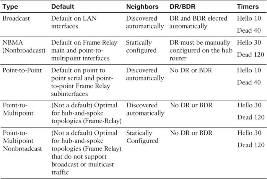
Table 15-3 OSPF Network Types and Characteristics
To determine the network type associated with an OSPF-enabled interface, issue the command show ip ospf interface interface_type interface_number. In Example 15-22, R1’s interface Gig1/0 is using the OSPF network type Broadcast. Use the spot-the-difference troubleshooting method when determining whether the network types do not match.
Example 15-22 Verifying OSPF Network Type
R1#show ip ospf interface gigabitEthernet 1/0
GigabitEthernet1/0 is up, line protocol is up
Internet Address 10.1.12.1/24, Area 1, Attached via Interface Enable
Process ID 1, Router ID 10.1.12.1, Network Type BROADCAST, Cost: 1
Topology-MTID Cost Disabled Shutdown Topology Name
0 1 no no Base
Enabled by interface config, including secondary ip addresses
Transmit Delay is 1 sec, State BDR, Priority 1
Designated Router (ID) 10.1.23.2, Interface address 10.1.12.2
Backup Designated router (ID) 10.1.12.1, Interface address 10.1.12.1
Timer intervals configured, Hello 10, Dead 40, Wait 40, Retransmit 5
oob-resync timeout 40
Hello due in 00:00:07
Supports Link-local Signaling (LLS)
Cisco NSF helper support enabled
IETF NSF helper support enabled
Index 1/1, flood queue length 0
Next 0x0(0)/0x0(0)
Last flood scan length is 1, maximum is 1
Last flood scan time is 4 msec, maximum is 4 msec
Neighbor Count is 1, Adjacent neighbor count is 1
Adjacent with neighbor 10.1.23.2 (Designated Router)
Suppress hello for 0 neighbor(s)
Message digest authentication enabled
Youngest key id is 1
Troubleshooting OSPFv2 Routes
As discussed already, neighbor relationships are the foundation for OSPF information sharing. If we have no neighbors, we will not learn any routes. So, besides the lack of a neighbor, what would be reasons for missing routes in an OSPF network?
Following is a listing of some common reasons as to why OSPF routes might be missing either in the LSDB or the routing table:
![]() Interface not running the OSPF process: If the interface is not participating in the OSPF process, the network the interface is part of will not be injected into the OSPF process and therefore will not be advertised to neighbors.
Interface not running the OSPF process: If the interface is not participating in the OSPF process, the network the interface is part of will not be injected into the OSPF process and therefore will not be advertised to neighbors.
![]() Better source of information: If the exact same network is learned from a more reliable source, it is used instead of the OSPF-learned information.
Better source of information: If the exact same network is learned from a more reliable source, it is used instead of the OSPF-learned information.
![]() Route filtering: A filter might be set up that is preventing a route from being installed in the routing table.
Route filtering: A filter might be set up that is preventing a route from being installed in the routing table.
![]() Stub area configuration: If the wrong type of stub area is chosen, you might be receiving a default route instead of the actual route.
Stub area configuration: If the wrong type of stub area is chosen, you might be receiving a default route instead of the actual route.
![]() Interface is shut down: The OSPF-enabled interface must be up/up for the network associated with the interface to be advertised.
Interface is shut down: The OSPF-enabled interface must be up/up for the network associated with the interface to be advertised.
![]() Wrong designated router was elected: In a hub-and-spoke environment, if the wrong router is the DR, routes will not be exchanged properly.
Wrong designated router was elected: In a hub-and-spoke environment, if the wrong router is the DR, routes will not be exchanged properly.
![]() Duplicate RIDs: If there are two or more routers with the same RID, routes will be missing in the topology.
Duplicate RIDs: If there are two or more routers with the same RID, routes will be missing in the topology.
Let’s take a look at each of these individually and identify how we can recognize them during the troubleshooting process.
Interface Not Running the OSPF Process
As discussed earlier, when you use the network area command or the ip ospf area interface command, the OSPF process is enabled on interfaces. OSPF then takes the network/subnet the interface is part of and injects it into the link-state database (LSDB) so that it can be advertised to other routers in the autonomous system. Therefore, even interfaces that will not form neighbor relationships with other routers need to be participating in the OSPF process for the interfaces network ID to be advertised.
As discussed in an earlier section, the output of show ip protocols displays the network area statements in addition to the interfaces that were explicitly configured with the ip ospf area interface command. Focus on the highlighted text in Example 15-23. Notice that it states Routing for Networks. Those are not the networks we are routing for. We are routing for the networks associated with the interface OSPF will be enabled on, based on the network statement. So, 10.1.1.1 0.0.0.0 area 1 means to enable OSPF on the interface with the IP address 10.1.1.1 and place it in area 1. We will then route for the network associated with that interface. Also, you can see that Gig1/0 was explicitly configured to participate in the OSPF process; therefore, OSPF will route for the network associated with that interface as well.
Example 15-23 Verifying OSPF-Enabled Interfaces with show ip protocols
R1#show ip protocols
*** IP Routing is NSF aware ***
Routing Protocol is "ospf 1"
Outgoing update filter list for all interfaces is not set
Incoming update filter list for all interfaces is not set
Router ID 10.1.12.1
Number of areas in this router is 1. 1 normal 0 stub 0 nssa
Maximum path: 4
Routing for Networks:
10.1.1.1 0.0.0.0 area 1
Routing on Interfaces Configured Explicitly (Area 1):
GigabitEthernet1/0
Passive Interface(s):
Ethernet0/0
GigabitEthernet0/0
Routing Information Sources:
Gateway Distance Last Update
10.1.23.2 110 01:00:43
10.1.23.3 110 01:00:43
Distance: (default is 110)
So, what networks are we actually routing for then? The networks associated with the interfaces that are now enabled for OSPF. In Example 15-24, you can see the output of the show ip interface command on R1 for Gig0/0 and Gig1/0, which was piped to only include the Internet address. Notice that they are in a /24 network. As a result, the network IDs would be 10.1.1.0/24 and 10.1.12.0/24. Those are the networks we are routing for.
Example 15-24 Verifying Network IDs with show ip interface
R1#show ip interface gi0/0 | i Internet
Internet address is 10.1.1.1/24
R1#show ip interface gi1/0 | i Internet
Internet address is 10.1.12.1/24
Better Source of Information
For an OSPF-learned route to be installed in the routing table, it has to be the most believable routing source. Recall that this is based on administrative distance (AD). OSPF’s AD is 110 for all learned routes: intra, inter, and external. Therefore, if there is another source that is educating the same router about the exact same network and that source has a better AD, the source with the better AD wins, and its information will be installed in the routing table. Example 15-25 is displaying only the OSPF-installed routes in the router. Notice that there is no OSPF entry for the network 10.1.1.0/24 and 10.1.12.0/24.
Example 15-25 Sample show ip route ospf Command Output
R1#show ip route ospf
Codes: L - local, C - connected, S - static, R - RIP, M - mobile, B - BGP
D - EIGRP, EX - EIGRP external, O - OSPF, IA - OSPF inter area
N1 - OSPF NSSA external type 1, N2 - OSPF NSSA external type 2
E1 - OSPF external type 1, E2 - OSPF external type 2
i - IS-IS, su - IS-IS summary, L1 - IS-IS level-1, L2 - IS-IS level-2
ia - IS-IS inter area, * - candidate default, U - per-user static route
o - ODR, P - periodic downloaded static route, H - NHRP, l - LISP
+ - replicated route, % - next hop override
Gateway of last resort is 10.1.12.2 to network 0.0.0.0
O*E2 0.0.0.0/0 [110/1] via 10.1.12.2, 01:15:29, GigabitEthernet1/0
10.0.0.0/8 is variably subnetted, 6 subnets, 2 masks
O IA 10.1.3.0/24 [110/3] via 10.1.12.2, 01:15:29, GigabitEthernet1/0
O IA 10.1.23.0/24 [110/2] via 10.1.12.2, 01:15:29, GigabitEthernet1/0
O IA 203.0.113.0/24 [110/3] via 10.1.12.2, 01:15:29, GigabitEthernet1/0
In this case, there is a better source for the 10.1.1.0/24 and 10.1.12.0/24 networks. Example 15-26 displays the output of the show ip route 10.1.1.0 255.255.255.0 command. It identifies that this network is directly connected and has an AD of 0. Because a directly connected network has an AD of 0 and an OSPF route has an AD of 110, the directly connected source is installed in the routing table.
Example 15-26 Sample show ip route 10.1.1.0 255.255.255.0 Command Output
R1#show ip route 10.1.1.0 255.255.255.0
Routing entry for 10.1.1.0/24
Known via "connected", distance 0, metric 0 (connected, via interface)
Routing Descriptor Blocks:
* directly connected, via GigabitEthernet0/0
Route metric is 0, traffic share count is 1
But wait, you might be questioning whether 10.1.1.0/24 is in the LSDB, because it is directly connected. Remember, when an interface is participating in the routing process, its network will be injected into the LSDB as a Type 1 (Router) LSA. You can verify this with the show ip ospf database command, as shown in Example 15-27. However, there is no listing for 10.1.1.0/24. This is because we are only looking at a summary of the LSAs in the LSDB. If you want to see the specifics of the LSA, you have to open them up. Example 15-28 displays the output of show ip ospf database router 10.1.12.1. This command opens the Type 1 Router LSA advertised by the router with the RID 10.1.12.1, which is R1. It displays that 10.1.1.0/24 is in the LSDB and therefore can be advertised in the OSPF process.
Example 15-27 Output of show ip ospf database on R1
R1#show ip ospf database
OSPF Router with ID (10.1.12.1) (Process ID 1)
Router Link States (Area 1)
Link ID ADV Router Age Seq# Checksum Link count
10.1.12.1 10.1.12.1 1025 0x80000009 0x006B41 2
10.1.23.2 10.1.23.2 1210 0x8000002D 0x00E7A3 1
Net Link States (Area 1)
Link ID ADV Router Age Seq# Checksum
10.1.12.2 10.1.23.2 1210 0x80000007 0x00B307
Summary Net Link States (Area 1)
Link ID ADV Router Age Seq# Checksum
10.1.3.0 10.1.23.2 1210 0x80000004 0x00D72E
10.1.23.0 10.1.23.2 1210 0x8000001A 0x00C418
203.0.113.0 10.1.23.2 1210 0x80000004 0x004E88
Summary ASB Link States (Area 1)
Link ID ADV Router Age Seq# Checksum
10.1.23.3 10.1.23.2 1210 0x80000003 0x00C629
Type-5 AS External Link States
Link ID ADV Router Age Seq# Checksum Tag
0.0.0.0 10.1.23.3 1268 0x80000003 0x00B399 1
Example 15-28 Output of show ip ospf database router 10.1.12.1 on R1
R1#show ip ospf database router 10.1.12.1
OSPF Router with ID (10.1.12.1) (Process ID 1)
Router Link States (Area 1)
LS age: 1368
Options: (No TOS-capability, DC)
LS Type: Router Links
Link State ID: 10.1.12.1
Advertising Router: 10.1.12.1
LS Seq Number: 80000009
Checksum: 0x6B41
Length: 48
Number of Links: 2
Link connected to: a Transit Network
(Link ID) Designated Router address: 10.1.12.2
(Link Data) Router Interface address: 10.1.12.1
Number of MTID metrics: 0
TOS 0 Metrics: 1
Link connected to: a Stub Network
(Link ID) Network/subnet number: 10.1.1.0
(Link Data) Network Mask: 255.255.255.0
Number of MTID metrics: 0
TOS 0 Metrics: 1
Having a better source of routing information may not cause users to complain or submit a trouble ticket, because they will probably still be able to access the resources they need to. However, it might be causing suboptimal routing in your network. Review Figure 15-1, which shows a network running two different routing protocols. In this case, which path will be used to send traffic from PC1 to 10.1.1.0/24? If you said the longer EIGRP path, you are correct. Even though it is quicker to use the OSPF path, EIGRP wins by default because it has the lower AD and suboptimal routing occurs.
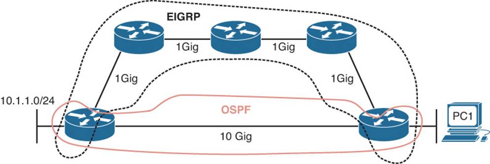
Figure 15-1 Using an EIGRP Path, Which Is Suboptimal
Being able to recognize when a certain routing source should be used and when it should not be used is key to optimizing your network and reducing the number of troubleshooting instances related to “the network is slow.” In this case, we might want to consider increasing the AD of EIGRP or lowering the AD of OSPF to optimize routing.
Route Filtering
A distribute list applied to an Open Shortest Path First (OSPF) process controls which routes are installed into the routing table from the LSDB. Realize that this differs from EIGRP, where it controls routes sent and received between neighbors. The reason this difference exists is that all OSPF routers in an area must have the same LSDB. If you were able to control the routes sent to and received from neighbors, the LSDB would not be the same amongst the routers in the area, which is not permitted.
To apply a route filter to OSPF, the distribute list is applied in OSPF configuration mode inbound (meaning into the routing table), and the routes installed are controlled by ACLs, prefix lists, or route maps. Therefore, when troubleshooting route filtering for OSPF, you need to consider the following:
![]() Is the distribute list applied in the correct direction?
Is the distribute list applied in the correct direction?
![]() If the distribute list is using an ACL, is the ACL correct?
If the distribute list is using an ACL, is the ACL correct?
![]() If the distribute list is using a prefix list, is the prefix list correct?
If the distribute list is using a prefix list, is the prefix list correct?
![]() If the distribute list is using a route map, is the route map correct?
If the distribute list is using a route map, is the route map correct?
The show ip protocols command will identify whether a distribute list is applied to the OSPF process, as shown in Example 15-29. This example indicates that there are no outbound filters and that there is an inbound filter that is referencing the prefix list called TEST.
Example 15-29 Verifying Route Filters with show ip protocols
R1#show ip protocols
*** IP Routing is NSF aware ***
Routing Protocol is "ospf 1"
Outgoing update filter list for all interfaces is not set
Incoming update filter list for all interfaces is (prefix-list) TEST
Router ID 10.1.12.1
Number of areas in this router is 1. 1 normal 0 stub 0 nssa
Maximum path: 4
Routing for Networks:
10.1.1.1 0.0.0.0 area 1
Routing on Interfaces Configured Explicitly (Area 1):
GigabitEthernet1/0
Passive Interface(s):
Ethernet0/0
GigabitEthernet0/0
Routing Information Sources:
Gateway Distance Last Update
10.1.23.2 110 00:00:20
10.1.23.3 110 00:00:20
Distance: (default is 110)
The inbound filter in Example 15-29 is filtered by prefix list TEST. To verify the entries in this prefix list, you issue the show ip prefix-list TEST command, as shown in Example 15-30. If an ACL were applied, you would issue the show access-list command. If a route map were applied, you would issue the show route-map command.
As displayed in Example 15-30, you can verify the command that was used to apply the distribute list in the running configuration.
Example 15-30 Verifying the OSPF Distribute List and Prefix List
R1#show ip prefix-list TEST
ip prefix-list TEST: 2 entries
seq 5 deny 10.1.23.0/24
seq 10 permit 0.0.0.0/0 le 32
R1#show run | section router ospf 1
router ospf 1
area 1 authentication message-digest
passive-interface default
no passive-interface GigabitEthernet1/0
network 10.1.1.1 0.0.0.0 area 1
distribute-list prefix TEST in
Notice in Example 15-31 that the LSDB still has the 10.1.23.0/24 network listed but that it is not installed in the routing table because of the distribute list that is denying 10.1.23.0/24 from being installed.
Example 15-31 Verifying OSPF Routes and LSDB After a Distribute List Is Applied
R1#show ip ospf database
OSPF Router with ID (10.1.12.1) (Process ID 1)
Router Link States (Area 1)
Link ID ADV Router Age Seq# Checksum Link count
10.1.12.1 10.1.12.1 16 0x80000011 0x005B49 2
10.1.23.2 10.1.23.2 13 0x80000033 0x00DBA9 1
Net Link States (Area 1)
Link ID ADV Router Age Seq# Checksum
10.1.12.2 10.1.23.2 12 0x8000000D 0x00A70D
Summary Net Link States (Area 1)
Link ID ADV Router Age Seq# Checksum
10.1.3.0 10.1.23.2 16 0x80000002 0x00DB2C
10.1.23.0 10.1.23.2 16 0x80000002 0x00F4FF
203.0.113.0 10.1.23.2 16 0x80000002 0x005286
Summary ASB Link States (Area 1)
Link ID ADV Router Age Seq# Checksum
10.1.23.3 10.1.23.2 18 0x80000001 0x00CA27
Type-5 AS External Link States
Link ID ADV Router Age Seq# Checksum Tag
0.0.0.0 10.1.23.3 779 0x80000005 0x00AF9B 1
R1#show ip route
...output omitted...
Gateway of last resort is 10.1.12.2 to network 0.0.0.0
O*E2 0.0.0.0/0 [110/1] via 10.1.12.2, 00:00:02, GigabitEthernet1/0
10.0.0.0/8 is variably subnetted, 5 subnets, 2 masks
C 10.1.1.0/24 is directly connected, GigabitEthernet0/0
L 10.1.1.1/32 is directly connected, GigabitEthernet0/0
O IA 10.1.3.0/24 [110/3] via 10.1.12.2, 00:00:02, GigabitEthernet1/0
C 10.1.12.0/24 is directly connected, GigabitEthernet1/0
L 10.1.12.1/32 is directly connected, GigabitEthernet1/0
O IA 203.0.113.0/24 [110/3] via 10.1.12.2, 00:00:02, GigabitEthernet1/0
Stub Area Configuration
Because all routers in an area need to have the same LSDB, you cannot manipulate the LSAs within an area; however, you can manipulate LSAs that are flowing between areas by using the stub and NSSA OSPF features.
When you create stub or NSSA areas, you suppress Type 5 LSAs from entering into an area at the ABR. With totally stubby and totally NSSA areas, you suppress Type 5 and Type 3 LSAs from entering into an area at the ABR. The routes that would have been learned via the Type 5 and Type 3 LSAs in the area are now replaced by a default route. Because there is a default route, the router has lost visibility of the overall network, and this could produce suboptimal routing if not implemented correctly in highly redundant environments.
As a result, if you are expecting a Type 5 or Type 3 LSA for a specific route but it is not showing up in the area, verify whether the area is a stub or NSSA area and determine the types of routes that are being suppressed. You can verify whether the area connected to the router is a stub or NSSA area by using the show ip ospf command, as shown in Example 15-32.
Example 15-32 Determining the Type of OSPF Areas
R1#show ip ospf
Routing Process "ospf 1" with ID 10.1.12.1
Start time: 02:23:19.824, Time elapsed: 02:08:52.184
...output omitted...
Reference bandwidth unit is 100 mbps
Area 1
Number of interfaces in this area is 2
It is a stub area
Area has no authentication
SPF algorithm last executed 00:05:46.800 ago
...output omitted...
However, remember that when implementing totally stub or totally NSSA areas you are only configuring the no-summary keyword on the ABR. Therefore, it is best to review the output of show ip ospf on the ABR, as shown in Example 15-33. In this example, R2 is configured to suppress Type 3 and Type 5 LSAs from entering into area 1. It will replace them with a default route with a cost of 1.
Example 15-33 Determining the Type of OSPF Area on the ABR
R2#show ip ospf
Routing Process "ospf 1" with ID 10.1.23.2
Start time: 02:39:09.376, Time elapsed: 15:19:40.352
...output omitted...
Flood list length 0
Area 1
Number of interfaces in this area is 1
It is a stub area, no summary LSA in this area
Generates stub default route with cost 1
Area has no authentication
...output omitted...
Interface Is Shut Down
As discussed earlier, once the OSPF process is enabled on the interface, the network the interface is part of (the directly connected entry in the routing table) is injected into the OSPF process. If the interface is shut down, there is no directly connected entry for the network in the routing table. Therefore, the network does not exist, and no network can be injected into the OSPF process. The interface has to be up/up for routes to be advertised or for neighbor relationships to be formed.
Wrong Designated Router Was Elected
A multiaccess network can have multiple routers residing on a common network segment. Rather than having all routers form a full mesh of adjacencies with one another, a designated router (DR) will be elected, and all other routers on the segment form a full adjacency with the DR, as illustrated in Figure 15-2. The rest of the routers will form a 2Way adjacency with each other, and if a BDR exists, they will form a full adjacency with the BDR as well.
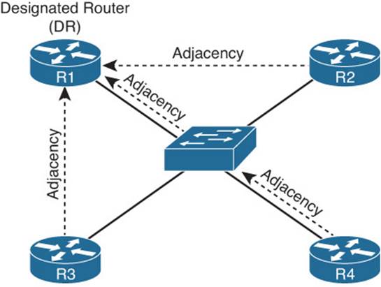
Figure 15-2 DR Election in an Ethernet Network
A DR is elected based on router priority, with larger priority values being more preferable. If routers have equal priorities, the DR is elected based on the highest OSPF RID. A BDR is also elected based on the same criteria. Routers on the multiaccess network form full adjacencies with the BDR in case the DR becomes unavailable.
It does not matter which router is elected as the DR in a multiaccess Ethernet topology or a full-mesh Frame Relay topology, because every router is able to reach the DR since the Layer 2 topology lines up with the Layer 3 addressing. However, over a hub-and-spoke nonbroadcast multiaccess (NBMA) network such as Frame Relay or with a Dynamic Multipoint VPN (DMVPN), it does matter who the DR is because the underlying Layer 2 topology does not line up with the Layer 3 addressing.
Refer to Figure 15-3 which displays a hub-and-spoke Frame Relay or DMVPN network. The multipoint interface (single physical interface or mGRE [multipoint generic routing encapsulation] tunnel interface) provides connectivity to multiple routers in the same subnet out the single interface, like Ethernet. However, in this case, the Layer 2 topology is not the same as the Layer 3 topology. The Layer 3 topology is indicating that all routers are directly reachable out the interfaces (same subnet). But the Layer 2 topology says otherwise. You cannot directly reach R2 from R3 and vice versa. You have to go through R1.
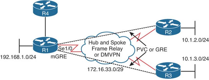
Figure 15-3 Hub and Spoke
Figure 15-4 shows the wrong DR placement. The DR router needs to be reachable via a single hop because of how OSPF neighbor relationships are formed and how routers communicate with the DR. Hellos are established with the multicast address 224.0.0.5, and the DR is reachable at the multicast address 224.0.0.6. Packets destined to these two multicast addresses will not be relayed by other routers. Because the DR is responsible for relaying learned routes in a multiaccess network, it needs to be centrally located. Therefore, if R2 were the DR, R3 would not be able to form an adjacency with it because R1 will not relay the hello packet. Therefore, R3 cannot communicate with the DR, meaning that it cannot tell the DR about the 10.1.3.0 network, and as a result, no other router will learn about the 10.1.3.0/24 network.
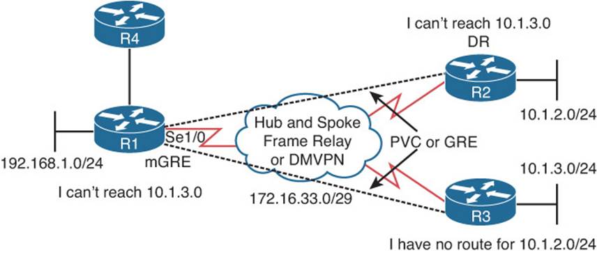
Figure 15-4 Wrong DR Placement
In this case, you need to control who the DR is. It has to be R1 to ensure that all routers are able to send LSAs to it and receive LSAs from it, as shown in Figure 15-5.
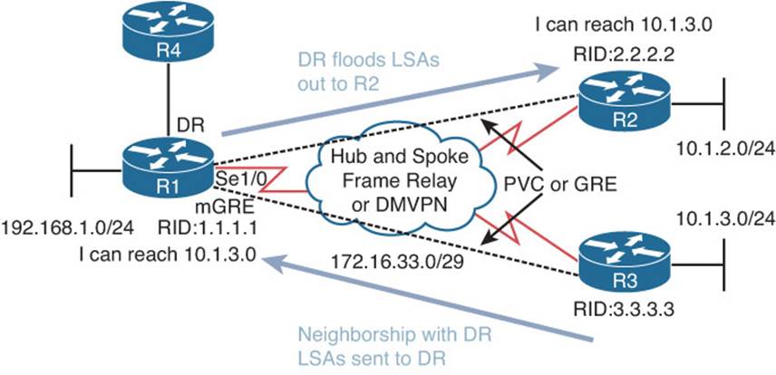
Figure 15-5 Correct DR Placement
To verify the DR placement, issue the command show ip ospf interface interface_type interface_number on each of the routers. Example 15-34 indicates that R1 considers the router with the RID 3.3.3.3 as the DR at interface 172.16.33.6. R2 considers itself as the DR and R1 as the BDR. R3 considers itself a DR and R1 as a BDR. Therefore, we have two DRs in this hub-and-spoke environment. As a result, routes will not be successfully learned by all routers in the topology.
Example 15-34 Verifying the DR
R1#show ip ospf interface ser 1/0
Serial1/0 is up, line protocol is up
Internet Address 172.16.33.4/29, Area 0, Attached via Network Statement
Process ID 1, Router ID 1.1.1.1, Network Type NON_BROADCAST, Cost: 64
Topology-MTID Cost Disabled Shutdown Topology Name
0 64 no no Base
Transmit Delay is 1 sec, State BDR, Priority 1
Designated Router (ID) 3.3.3.3, Interface address 172.16.33.6
Backup Designated router (ID) 1.1.1.1, Interface address 172.16.33.4
Timer intervals configured, Hello 30, Dead 120, Wait 120, Retransmit 5
...output omitted...
R2#show ip ospf interface ser 1/0
Serial1/0 is up, line protocol is up
Internet Address 172.16.33.5/29, Area 0, Attached via Network Statement
Process ID 1, Router ID 2.2.2.2, Network Type NON_BROADCAST, Cost: 64
Topology-MTID Cost Disabled Shutdown Topology Name
0 64 no no Base
Transmit Delay is 1 sec, State DR, Priority 1
Designated Router (ID) 2.2.2.2, Interface address 172.16.33.5
Backup Designated router (ID) 1.1.1.1, Interface address 172.16.33.4
Timer intervals configured, Hello 30, Dead 120, Wait 120, Retransmit 5
...output omitted...
R3#show ip ospf interface ser 1/0
Serial1/0 is up, line protocol is up
Internet Address 172.16.33.6/29, Area 0, Attached via Network Statement
Process ID 1, Router ID 3.3.3.3, Network Type NON_BROADCAST, Cost: 64
Topology-MTID Cost Disabled Shutdown Topology Name
0 64 no no Base
Transmit Delay is 1 sec, State DR, Priority 1
Designated Router (ID) 3.3.3.3, Interface address 172.16.33.6
Backup Designated router (ID) 1.1.1.1, Interface address 172.16.33.4
Timer intervals configured, Hello 30, Dead 120, Wait 120, Retransmit 5
...output omitted...
To fix this issue, you need to force R1 to be the DR by preventing R2 and R3 from ever wanting to be a DR. On R2 and R3, you go to interface configuration mode and set the OSPF priority to 0, as shown in Example 15-35.
Example 15-35 Changing OSPF Priority on Spokes
R2#config t
R2(config)#int ser 1/0
R2(config-if)#ip ospf priority 0
R3#config t
R3(config)#int ser 1/0
R3(config-if)#ip ospf priority 0
Now the output of show ip ospf interface ser 1/0 on R1, as shown in Example 15-36, indicates that it is the DR and that there are no BDRs, because we never want a spoke to back up the DR because it would cause the same problem we discussed earlier.
Example 15-36 Verifying the Hub Router Is the DR
R1#show ip ospf interface ser 1/0
Serial1/0 is up, line protocol is up
Internet Address 172.16.33.4/29, Area 0, Attached via Network Statement
Process ID 1, Router ID 1.1.1.1, Network Type NON_BROADCAST, Cost: 64
Topology-MTID Cost Disabled Shutdown Topology Name
0 64 no no Base
Transmit Delay is 1 sec, State DR, Priority 1
Designated Router (ID) 1.1.1.1, Interface address 172.16.33.4
No backup designated router on this network
Old designated Router (ID) 3.3.3.3, Interface address 172.16.33.6
...output omitted...
Duplicate Router IDs
The RID uniquely identifies the routers in the OSPF domain. Because the RID is used during the formation of neighbor relationships and to determine which router is advertising a specific LSA, it is imperative that the RIDs are unique in the domain. If there are duplicate RIDs, the network issues can vary. For example, in the same area, the routers are going to see a Type 1 Router LSA about networks they do not know about from a RID the same as theirs. Therefore, they think they generated the LSA. A router will not use information contained in an LSA they receive that was generated by them because it means there is a loop. However, the LSA is not from itself, it just has the same RID, and as a result we have missing routes on various routers in the domain.
In Figure 15-6, the Type 1 Router LSA from R1 is ignored by R3 because the LSA has the same RID as R3 and so R3 thinks it is its own LSA. Therefore, R3 does not learn about 10.1.1.0/24. The same is true for R1; it does not learn about 10.1.3.0/24 because it is ignoring the LSA that R3 sent because it has the same RID.
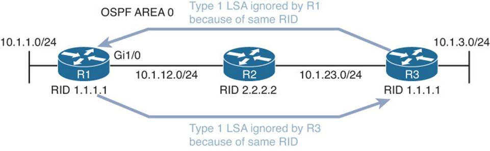
Figure 15-6 Duplicate RIDs in the Same Area
What about duplicate RIDs in different areas? This would cause the physical OSPF topology to be different from what the SPF algorithm sees it as. Refer to Figure 15-7, which displays an OSPF domain with duplicate RIDs in different areas. R1 and R4 both have a RID of 1.1.1.1. As you can see, R2 is going to see the router with the RID in both area 0 and area 1 (which to R2 is technically the same router, but in this case, physically it is not). This can cause routing issues because some routes may not be passed between areas, causing the LSDB and the routing tables to be incomplete.
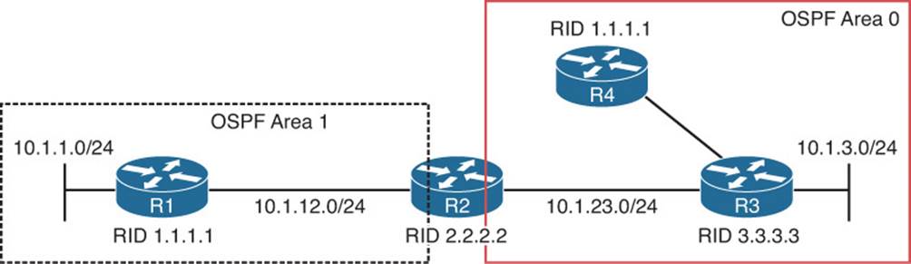
Figure 15-7 Duplicate RIDs in Different Areas
If you have exhausted all possible reasons as to why routes are not appearing in the LSDB or the routing table, take a look at the RIDs of the routers using the show ip protocols command, as shown in Example 15-37.
Example 15-37 Verifying OSPF RID
R1#show ip protocols
*** IP Routing is NSF aware ***
Routing Protocol is "ospf 1"
Outgoing update filter list for all interfaces is not set
Incoming update filter list for all interfaces is not set
Router ID 1.1.1.1
Number of areas in this router is 1. 0 normal 1 stub 0 nssa
Maximum path: 4
...output omitted...
Troubleshooting Miscellaneous OSPFv2 Issues
So far, your focus has been on troubleshooting issues related to OSPFv2 neighbor relationships and routes. Now your focus will be on tracking LSAs through the network, route summarization, discontiguous areas, load balancing, and default routes.
Tracking OSPF Advertisements Through a Network
When troubleshooting an OSPF issue, tracking the path of OSPF advertisements can be valuable in determining why certain entries are in a router’s LSDB.
As an example, notice network 192.168.1.0/24 in the topology provided in Figure 15-8, and consider how this network is entered into the LSDB of the other OSPF routers.
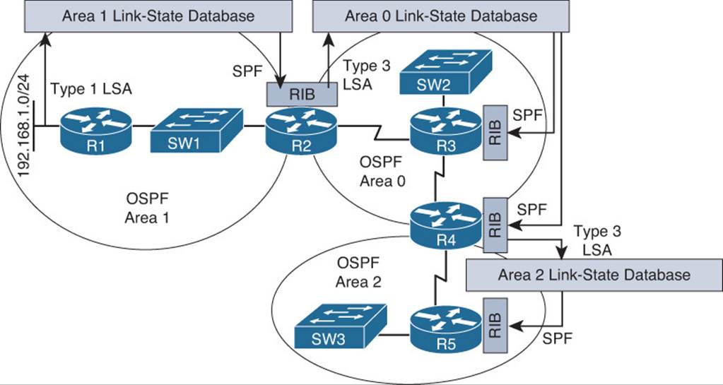
Figure 15-8 Tracking an OSPF Advertisement
The following steps describe how network 192.168.1.0/24, which is directly connected to router R1, is learned by the LSDB of routers R2, R3, R4, and R5:
Step 1. Router R1 creates a Type 1 Router LSA for the 192.168.1.0/24 network in the area 1 link-state database and floods it into area 1.
Step 2. Router R2 receives the Router LSA for 192.168.1.0/24 and places it in the area 1 link-state database. R2 runs the shortest path first (SPF) algorithm to determine the best path through area 1 to reach the 192.168.1.0/24 network. The best result is placed in R2’s routing table (RIB).
Step 3. Router R2 informs area 0 routers about the network 192.168.1.0/24 by injecting a Type 3 LSA about the network into the link-state database of area 0 and flooding it into area 0. This LSA includes the cost to reach the 192.168.1.0/24 network, from the perspective of router R2.
Step 4. Each of the other area 0 routers (that is, routers R3 and R4) receive the Type 3 LSA and add it to their area 0 LSDB. They run the SPF algorithm to determine the cost to reach router R2. This cost is then added to the cost router R2 advertised in its Type 3 LSA, and the result is stored in the RIB for routers R3 and R4.
Step 5. Router R4 informs area 2 routers about the network 192.168.1.0/24 by injecting a Type 3 LSA about the network into the link-state database of area 2 and flooding it into area 2. This LSA includes the cost to reach the 192.168.1.0/24 network, from the perspective of router R4.
Step 6. Each of the routers in area 2 receive the Type 3 LSA and add it to their area 2 LSDB. They run the SPF algorithm to determine the cost to reach router R4. This cost is then added to the cost router R4 advertised in its Type 3 LSA, and the result is stored in the RIB of the routers.
To successfully troubleshoot OSPF-related issues, you should have a solid understanding of this process and the different types of OSPF LSAs. Table 15-4 lists the common LSA types you will encounter when troubleshooting a Cisco-based OSPF network.
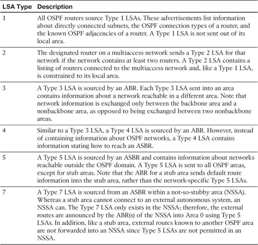
Table 15-4 OSPF LSAs
Route Summarization
OSPF is strict about where route summarization can occur. With OSPF, manual route summarization is enabled on an area by area basis on an ABR to summarize routes as they enter or leave an area or on an ASBR to summarize external routes being injected into an area. Therefore, when troubleshooting route summarization you want to keep the following in mind:
![]() Did you enable route summarization on the correct router?
Did you enable route summarization on the correct router?
![]() Did you enable route summarization for the correct area?
Did you enable route summarization for the correct area?
![]() Did you create the appropriate summary route?
Did you create the appropriate summary route?
You can verify all of these using the show ip ospf command, as shown in Example 15-38. In this example, R2 is an area border router, and there is a summary address of 10.1.0.0/16 for area 1 that is currently active and being advertised into area 0.
Example 15-38 Verifying Interarea Route Summarization with show ip ospf
R2#show ip ospf
Routing Process "ospf 1" with ID 2.2.2.2
...output omitted...
Event-log enabled, Maximum number of events: 1000, Mode: cyclic
It is an area border router
Router is not originating router-LSAs with maximum metric
...output omitted...
Reference bandwidth unit is 100 mbps
Area BACKBONE(0)
Number of interfaces in this area is 1
Area has no authentication
SPF algorithm last executed 00:03:27.000 ago
SPF algorithm executed 14 times
Area ranges are
Number of LSA 6. Checksum Sum 0x033162
Number of opaque link LSA 0. Checksum Sum 0x000000
Number of DCbitless LSA 0
Number of indication LSA 0
Number of DoNotAge LSA 0
Flood list length 0
Area 1
Number of interfaces in this area is 1
Area has no authentication
SPF algorithm last executed 00:03:27.024 ago
SPF algorithm executed 13 times
Area ranges are
10.1.0.0/16 Active(1) Advertise
Number of LSA 9. Checksum Sum 0x0555F1
...output omitted...
Remember that interarea summaries are created on ABRs with the area range command and that external summaries are created on ASBRs with the summary-address command.
When a summary route is created on a router, so is a summary route to Null0, as shown in Example 15-39. This route to Null0 is created to prevent routing loops. It is imperative that this route is in the table to ensure that if a packet is received by this router destined to a network that falls within the summary that the router does not really know how to reach (longer match), it will be dropped. If the route to Null0 did not exist, and there were a default route on the router, the router would forward the packet via the default route, and then the next-hop router would end up forwarding it back to this router, because it is using the summary route, then the local router would then forward it based on the default route, and then it would come back. This is a routing loop.
It is important that you create accurate summary routes to ensure that your router is not advertising networks in the summary route that it does not truly know how to reach. If it does, it is possible that it might receive packets to destinations that fall within the summary that it really does not know how to reach. If this is the case, it means that packets will be dropped because of the route to Null0.
Example 15-39 Verifying Local Summary Route to Null0
R2#show ip route | include Null
O 10.1.0.0/16 is a summary, 00:16:07, Null0
Unlike EIGRP, which gives the route to Null0 an AD of 5, the route to Null0 gets an AD of 110 with OSPF, as shown in Example 15-40. This does not ensure that it is more believable than most of the other sources of routing information. Therefore, it is possible that another better routing source could end up forwarding the traffic for networks that are included in the summary route to Null0.
Example 15-40 Verifying the AD of a Local Summary Route to Null 0
R2#show ip route 10.1.0.0 255.255.0.0
Routing entry for 10.1.0.0/16
Known via "ospf 1", distance 110, metric 1, type intra area
Routing Descriptor Blocks:
* directly connected, via Null0
Route metric is 1, traffic share count is 1
Discontiguous Areas
In a multiarea OSPF network, a backbone area (numbered area 0) must exist, and all other areas must connect to area 0. If an area is not physically adjacent to area 0, routes will not be successfully learned by all routers in the OSPF domain. To solve this issue, a virtual link can be configured to logically connect the nonadjacent area with area 0. Figure 15-9 shows area 51 not physically connected to area 0. This results in the 10.1.4.0 network not being learned by any other router in the OSPF domain, because an ABR is needed to send Type 3 LSAs into area 0. R4 is not an ABR in this case because the requirement for an ABR is that one interface must be in area 0 and one or more interfaces in any other area(s). In this case, R4 has no interfaces in area 0.
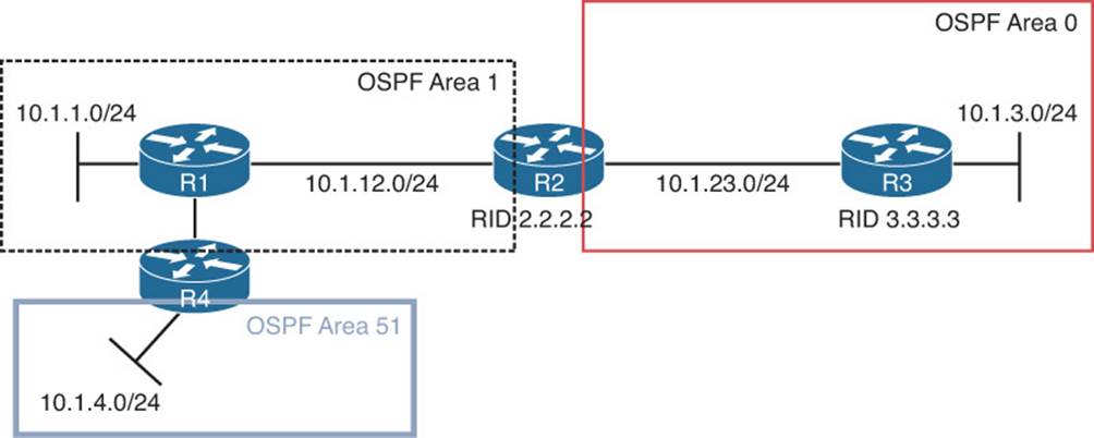
Figure 15-9 Area 51 Not Directly Connected to Area 0
Now refer to Figure 15-10, which is showing a similar topology; however, area 0 is discontiguous. This will result in LSAs not being successfully flooded though the OSPF domain and, as a result, incomplete routing tables.
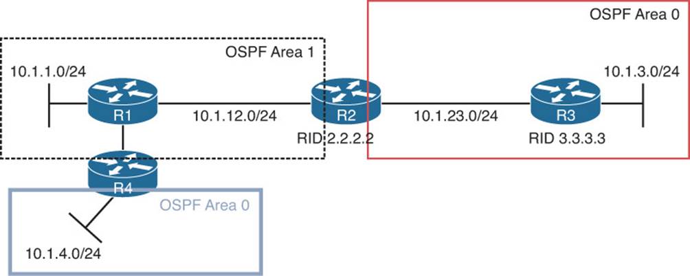
Figure 15-10 Discontiguous Area 0
You need to be able to recognize these OSPF design issues, understand how to troubleshoot them and implement a solution. The solution is virtual links. A virtual link in both these examples is created through area 1, which will be known as the transit area because it will transit LSAs from area 51 to area 0 or from area 0 to area 0. Note that virtual links are a temporary solution for these issues. A permanent redesign/fix should be performed as soon as possible.
The virtual link is created between the routers connected to the transit area using their RIDs and the transit area number as shown in Figure 15-11. The router OSPF configuration mode command on R2 is area 1 virtual-link 4.4.4.4, and the command on R4 is area 1 virtual-link 2.2.2.2. Once the virtual link is established, R4 becomes an ABR since it has an interface (virtual interface in this case) in area 0. Common issues related to failed virtual links include a misconfigured area number or RID. If you type in the area number you are trying to connect to area 0 instead of the transit area number, the virtual link will fail to form. If you use the interface IP address rather than the RID, the virtual link will fail to form.
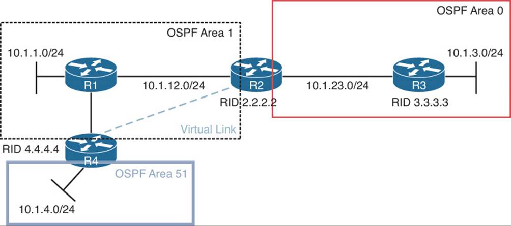
Figure 15-11 LSA Flooding with Virtual Links
Example 15-41 displays the output of show ip ospf neighbor on R2. Notice how there is a new neighbor relationship with 4.4.4.4 but that the local interface is OSPF_VL0, which is referring to the virtual link interface.
Example 15-41 Verifying a Neighbor Relationship over a Virtual Link
R2#show ip ospf neighbor
Neighbor ID Pri State Dead Time Address Interface
4.4.4.4 0 FULL/ - - 10.1.14.4 OSPF_VL0
3.3.3.3 1 FULL/BDR 00:00:34 10.1.23.3 GigabitEthernet1/0
1.1.1.1 1 FULL/BDR 00:00:35 10.1.12.1 GigabitEthernet0/0
Example 15-42 displays the output of show ip ospf virtual-links, which provides more details about the virtual link. It is not only important to verify that the virtual link is up but that the state is full, which verifies that LSAs have been successfully exchanged.
Example 15-42 Verifying the Virtual Link
R2#show ip ospf virtual-links
Virtual Link OSPF_VL0 to router 4.4.4.4 is up
Run as demand circuit
DoNotAge LSA allowed.
Transit area 1, via interface GigabitEthernet0/0
Topology-MTID Cost Disabled Shutdown Topology Name
0 2 no no Base
Transmit Delay is 1 sec, State POINT_TO_POINT,
Timer intervals configured, Hello 10, Dead 40, Wait 40, Retransmit 5
Hello due in 00:00:09
Adjacency State FULL (Hello suppressed)
Index 2/3, retransmission queue length 0, number of retransmission 0
First 0x0(0)/0x0(0) Next 0x0(0)/0x0(0)
Last retransmission scan length is 0, maximum is 0
Last retransmission scan time is 0 msec, maximum is 0 msec
Load Balancing
OSPF only supports equal-cost load balancing. Therefore, when troubleshooting load balancing for OSPF, your two primary points of concern are the overall end-to-end cost and the maximum number of paths permitted for load balancing. To verify the maximum number of equal-cost paths an OSPF router is currently configured to support, use the show ip protocols command, as shown in Example 15-43. In this example, R1 is currently using the default value of 4.
If your topology is showing multiple paths to reach certain networks in your organization but they are not all showing up in the routing table, it is more than likely because 1) they are not equal-cost paths or 2) the maximum paths value is configured too low.
Example 15-43 Verifying the Maximum Number of Paths for Load Balancing
R1#show ip protocols
*** IP Routing is NSF aware ***
Routing Protocol is "ospf 1"
Outgoing update filter list for all interfaces is not set
Incoming update filter list for all interfaces is (prefix-list) TEST
Router ID 1.1.1.1
Number of areas in this router is 2. 2 normal 0 stub 0 nssa
Maximum path: 4
Routing for Networks:
10.1.1.1 0.0.0.0 area 1
Routing on Interfaces Configured Explicitly (Area 1):
GigabitEthernet1/0
...output omitted...
Default Route
With OSPF, a static default route is injected into the routing process using the default-information originate command, not the redistribute static command. Therefore, if you are troubleshooting why a static default route is not being advertised in the OSPF process, use the show run | section router ospf command to verify that the default-information originate command is being used.
OSPFv2 Trouble Tickets
This section presents various trouble tickets relating to the topics discussed earlier in the chapter. The purpose of these trouble tickets is to give a process that you can follow when troubleshooting in the real world or in an exam environment. All trouble tickets in this section are based on the topology depicted in Figure 15-12.
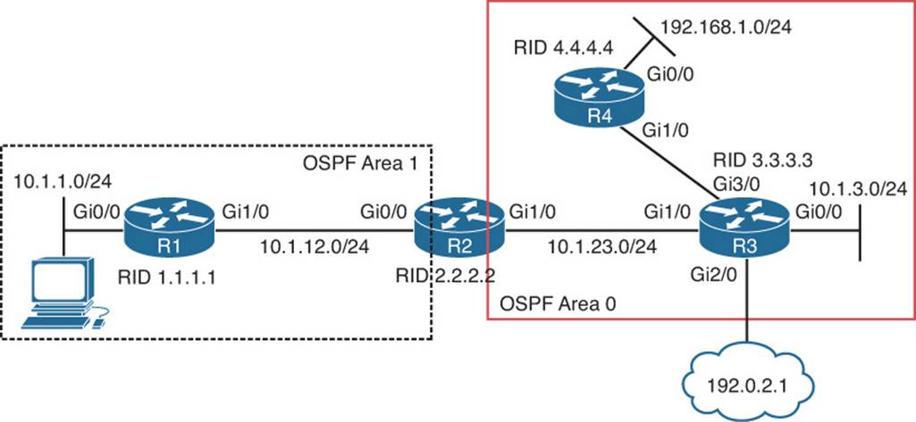
Figure 15-12 OSPFv2 Trouble Tickets Topology
Trouble Ticket 15-1
Problem: Users in the 10.1.1.0/24 network indicate that they are not able to access resources in the 192.168.1.0/24 network.
As always, the first item on the list for troubleshooting is to verify the problem. You access a PC in the 10.1.1.0/24 network and ping an IP address in the 192.168.1.0/24 network and it is successful (0% loss), as shown in Example 15-44. However, notice that the reply is from the default gateway at 10.1.1.1, and it states Destination host unreachable. Therefore, it was technically not successful.
Example 15-44 Destination Unreachable Result from a ping Command on a PC
C:\>ping 192.168.1.10
Pinging 192.168.1.10 with 32 bytes of data;
Reply from 10.1.1.1: Destination host unreachable.
Reply from 10.1.1.1: Destination host unreachable.
Reply from 10.1.1.1: Destination host unreachable.
Reply from 10.1.1.1: Destination host unreachable.
Ping statistics for 192.168.1.10:
Packets: Sent = 4, Received = 4, lost = 0 (0% loss),
Approximate round trip times in milli-seconds:
Minimum = 0ms, Maximum = 0ms, Average = 0ms
The result of this ping tells us two very important things: 1) The PC can reach the default gateway; 2) The default gateway does not know how to get to the 192.168.1.0/24 network. Therefore, we can focus our attention on R1 and work from there.
On R1, you issue the same ping, but it fails, as shown in Example 15-45.
Example 15-45 Failed Ping from R1 to 192.168.1.10
R1#ping 192.168.1.10
Type escape sequence to abort.
Sending 5, 100-byte ICMP Echos to 192.168.1.10, timeout is 2 seconds:
.....
Success rate is 0 percent (0/5)
Next, you check R1’s routing table with the show ip route command and notice that there are only connected routes in the routing table, as shown in Example 15-46. R1 is not learning any routes from R2.
Example 15-46 show ip route Output on R1
R1#show ip route
...output omitted...
Gateway of last resort is not set
10.0.0.0/8 is variably subnetted, 4 subnets, 2 masks
C 10.1.1.0/24 is directly connected, GigabitEthernet0/0
L 10.1.1.1/32 is directly connected, GigabitEthernet0/0
C 10.1.12.0/24 is directly connected, GigabitEthernet1/0
L 10.1.12.1/32 is directly connected, GigabitEthernet1/0
According to Figure 15-12, OSPF is the routing protocol in use. Therefore, you issue the show ip protocols command to verify that OSPF is running on R1. Example 15-47 displays the show ip protocols output and confirms that OSPF process 1 is in operation on R1.
Example 15-47 show ip protocols Output on R1
R1#show ip protocols
*** IP Routing is NSF aware ***
Routing Protocol is "ospf 1"
Outgoing update filter list for all interfaces is not set
Incoming update filter list for all interfaces is not set
Router ID 1.1.1.1
Number of areas in this router is 2. 2 normal 0 stub 0 nssa
Maximum path: 4
Routing for Networks:
10.1.1.1 0.0.0.0 area 1
Routing on Interfaces Configured Explicitly (Area 1):
GigabitEthernet1/0
Passive Interface(s):
Ethernet0/0
GigabitEthernet0/0
Routing Information Sources:
Gateway Distance Last Update
4.4.4.4 110 01:20:29
2.2.2.2 110 00:48:38
3.3.3.3 110 01:20:29
10.1.23.2 110 16:56:39
203.0.113.3 110 17:10:26
Distance: (default is 110)
Next you check to see whether R1 has any OSPF neighbors. According to the topology R2 should be a neighbor. To verify OSPF neighbors, you issue the show ip ospf neighbor command on R1, as shown in Example 15-48. According to the output, R1 is a neighbor with R2.
Example 15-48 show ip ospf neighbor Output on R1
R1#show ip ospf neighbor
Neighbor ID Pri State Dead Time Address Interface
2.2.2.2 1 FULL/DR 00:00:36 10.1.12.2 GigabitEthernet1/0
Now is the time to be wise. What is the next best step? Some would consider troubleshooting why the routes are missing on R1 by looking at various features and parameters associated with R1. However, the 192.168.1.0/24 network is in a different area. Who is responsible for telling R1 about 192.168.1.0/24? Is it R4? No. Is it R2? Yes. R2 sends a Type 3 Summary LSA into area 1 which tells area 1 about the 192.168.1.0/24 network. Therefore, if R2 does not know about 192.168.1.0/24 then we can stop troubleshooting on R1. This is a great example of how understanding the flow of different LSAs can save you time while troubleshooting.
On R2, you issue the show ip route command, as shown in Example 15-49, and confirm that R2 does not know about the 192.168.1.0/24 network either. In fact, it has not learned about any networks in area 0.
Example 15-49 show ip route Output on R2
R2#show ip route
...output omitted...
Gateway of last resort is not set
10.0.0.0/8 is variably subnetted, 6 subnets, 3 masks
O 10.1.0.0/16 is a summary, 15:15:33, Null0
O 10.1.1.0/24 [110/2] via 10.1.12.1, 01:33:14, GigabitEthernet0/0
C 10.1.12.0/24 is directly connected, GigabitEthernet0/0
L 10.1.12.2/32 is directly connected, GigabitEthernet0/0
C 10.1.23.0/24 is directly connected, GigabitEthernet1/0
L 10.1.23.2/32 is directly connected, GigabitEthernet1/0
Wait! Be careful with the previous statement. Remember, with OSPF, distribute lists are used to permit or deny routes from being installed in the routing table from the LSDB. Therefore, you may be learning about them just not installing them.
Example 15-50 shows the output of the LSDB on R2, and as you can see, there are no area 0 Type 1 Router LSAs from R3 (3.3.3.3) or R4 (4.4.4.4). Therefore, we can now officially say that R2 has not been educated about the networks that are missing.
Example 15-50 show ip ospf database Output on R2 Confirming that Routes are Missing
R2#show ip ospf database
OSPF Router with ID (2.2.2.2) (Process ID 1)
Router Link States (Area 0)
Link ID ADV Router Age Seq# Checksum Link count
2.2.2.2 2.2.2.2 316 0x80000025 0x003B9F 1
Summary Net Link States (Area 0)
Link ID ADV Router Age Seq# Checksum
10.1.0.0 2.2.2.2 1339 0x8000001C 0x00927B
Router Link States (Area 1)
Link ID ADV Router Age Seq# Checksum Link count
1.1.1.1 1.1.1.1 1988 0x80000022 0x007843 2
2.2.2.2 2.2.2.2 316 0x80000024 0x0012BA 1
Net Link States (Area 1)
Link ID ADV Router Age Seq# Checksum
10.1.12.2 2.2.2.2 1589 0x8000001C 0x007C75
Summary Net Link States (Area 1)
Link ID ADV Router Age Seq# Checksum
10.1.23.0 2.2.2.2 61 0x80000020 0x008C66
To receive LSAs, we must have interfaces participating in the OSPF process, and we must have neighbor relationships. The output of show cdp neighbors indicates that R3 is a neighbor and that it is reachable out R2’s local Gig1/0 interface, as shown in Example 15-51.
Example 15-51 Using show cdp neighbors to Verify Router Interfaces
R2#show cdp neighbors
Capability Codes: R - Router, T - Trans Bridge, B - Source Route Bridge
S - Switch, H - Host, I - IGMP, r - Repeater, P - Phone,
D - Remote, C - CVTA, M - Two-port Mac Relay
Device ID Local Intrfce Holdtme Capability Platform Port ID
R3 Gig 1/0 178 R 7206VXR Gig 1/0
R1 Gig 0/0 179 R 7206VXR Gig 1/0
Issuing the commands show ip ospf interface brief and show ip ospf neighbor, as shown in Example 15-52, shows that R2’s local Gig1/0 interface is participating in the OSPF process but does not have a neighbor on the interface.
Example 15-52 Verifying OSPF-Enabled Interfaces and Neighbors
R2#show ip ospf interface brief
Interface PID Area IP Address/Mask Cost State Nbrs F/C
Gi1/0 1 0 10.1.23.2/24 1 DR 0/0
Gi0/0 1 1 10.1.12.2/24 1 DR 1/1
R2#show ip ospf neighbor
Neighbor ID Pri State Dead Time Address Interface
1.1.1.1 1 FULL/BDR 00:00:37 10.1.12.1 GigabitEthernet0/0
So, you can now hypothesize that the issue is related to R2 and R3 not having a neighbor adjacency. What would cause this? As our earlier discussion in this chapter indicated, many different issues could cause this. However, if you recall, the majority of them were interface related, and we stated that using the spot-the-difference troubleshooting method would come in handy. Let’s do that by examining the output of show ip ospf interface gigabitethernet 1/0 on R2 and R3, as shown in Example 15-53.
Example 15-53 Comparing the OSPF Interface Parameters of R2 and R3
R2#show ip ospf interface gigabitEthernet 1/0
GigabitEthernet1/0 is up, line protocol is up
Internet Address 10.1.23.2/24, Area 0, Attached via Network Statement
Process ID 1, Router ID 2.2.2.2, Network Type BROADCAST, Cost: 1
Topology-MTID Cost Disabled Shutdown Topology Name
0 1 no no Base
Transmit Delay is 1 sec, State DR, Priority 1
Designated Router (ID) 2.2.2.2, Interface address 10.1.23.2
No backup designated router on this network
Timer intervals configured, Hello 11, Dead 44, Wait 44, Retransmit 5
oob-resync timeout 44
Hello due in 00:00:08
Supports Link-local Signaling (LLS)
Cisco NSF helper support enabled
IETF NSF helper support enabled
Index 1/2, flood queue length 0
Next 0x0(0)/0x0(0)
Last flood scan length is 0, maximum is 3
Last flood scan time is 0 msec, maximum is 4 msec
Neighbor Count is 0, Adjacent neighbor count is 0
Suppress hello for 0 neighbor(s)
Message digest authentication enabled
Youngest key id is 1
R3#show ip ospf interface gigabitEthernet 1/0
GigabitEthernet1/0 is up, line protocol is up
Internet Address 10.1.23.3/24, Area 0, Attached via Network Statement
Process ID 1, Router ID 3.3.3.3, Network Type BROADCAST, Cost: 1
Topology-MTID Cost Disabled Shutdown Topology Name
0 1 no no Base
Transmit Delay is 1 sec, State DR, Priority 1
Designated Router (ID) 3.3.3.3, Interface address 10.1.23.3
No backup designated router on this network
Timer intervals configured, Hello 10, Dead 40, Wait 40, Retransmit 5
oob-resync timeout 40
Hello due in 00:00:04
Supports Link-local Signaling (LLS)
Cisco NSF helper support enabled
IETF NSF helper support enabled
Index 2/2, flood queue length 0
Next 0x0(0)/0x0(0)
Last flood scan length is 1, maximum is 2
Last flood scan time is 0 msec, maximum is 4 msec
Neighbor Count is 0, Adjacent neighbor count is 0
Suppress hello for 0 neighbor(s)
Message digest authentication enabled
Youngest key id is 1
![]() Are the interfaces up? Yes
Are the interfaces up? Yes
![]() Are they in the same subnet? Yes
Are they in the same subnet? Yes
![]() Are they in the same area? Yes
Are they in the same area? Yes
![]() Do the routers have unique RIDs? Yes
Do the routers have unique RIDs? Yes
![]() Are they using compatible Network Types? Yes
Are they using compatible Network Types? Yes
![]() Do hello and dead timers match? No (possible reason)
Do hello and dead timers match? No (possible reason)
![]() Do authentication parameters match? Enabled and key matches, but not sure about key string unless we check the running configuration (possible reason)
Do authentication parameters match? Enabled and key matches, but not sure about key string unless we check the running configuration (possible reason)
As you can see in Example 15-53, the hello and dead timers do not match, but they must. Reviewing the output of show run interface gig 1/0 on R2, as shown in Example 15-54, shows that the command ip ospf hello-interval 11 was configured.
Example 15-54 Verifying Interface Configuration on R2
R2#show run interface gigabitEthernet 1/0
Building configuration...
Current configuration : 196 bytes
!
interface GigabitEthernet1/0
ip address 10.1.23.2 255.255.255.0
ip ospf authentication message-digest
ip ospf message-digest-key 1 md5 CISCO
ip ospf hello-interval 11
negotiation auto
end
Once you remove this command with the no ip ospf hello-interval 11 command, you receive the following syslog message on R2:
%OSPF-5-ADJCHG: Process 1, Nbr 3.3.3.3 on GigabitEthernet1/0 from LOADING to FULL, Loading Done
This confirms the adjacency was formed, and reviewing the output of the routing table on R2 using the show ip route command confirms that the routes are learned, as shown in Example 15-55.
Example 15-55 Verifying Routes in the Routing Table on R2
R2#show ip route
...output omitted...
Gateway of last resort is 10.1.23.3 to network 0.0.0.0
O*E2 0.0.0.0/0 [110/1] via 10.1.23.3, 00:01:00, GigabitEthernet1/0
10.0.0.0/8 is variably subnetted, 8 subnets, 3 masks
O 10.1.0.0/16 is a summary, 00:01:49, Null0
O 10.1.1.0/24 [110/2] via 10.1.12.1, 00:01:00, GigabitEthernet0/0
O 10.1.3.0/24 [110/2] via 10.1.23.3, 00:01:00, GigabitEthernet1/0
C 10.1.12.0/24 is directly connected, GigabitEthernet0/0
L 10.1.12.2/32 is directly connected, GigabitEthernet0/0
C 10.1.23.0/24 is directly connected, GigabitEthernet1/0
L 10.1.23.2/32 is directly connected, GigabitEthernet1/0
O 10.1.34.0/24 [110/2] via 10.1.23.3, 00:01:00, GigabitEthernet1/0
O 192.168.1.0/24 [110/3] via 10.1.23.3, 00:01:00, GigabitEthernet1/0
O 203.0.113.0/24 [110/2] via 10.1.23.3, 00:01:00, GigabitEthernet1/0
R1 also knows about the routes now, as shown in Example 15-56, which displays the output of show ip route on R1.
Example 15-56 Verifying Routes in the Routing Table on R1
R1#show ip route
...output omitted...
Gateway of last resort is 10.1.12.2 to network 0.0.0.0
O*E2 0.0.0.0/0 [110/1] via 10.1.12.2, 00:00:13, GigabitEthernet1/0
10.0.0.0/8 is variably subnetted, 7 subnets, 2 masks
C 10.1.1.0/24 is directly connected, GigabitEthernet0/0
L 10.1.1.1/32 is directly connected, GigabitEthernet0/0
O IA 10.1.3.0/24 [110/3] via 10.1.12.2, 00:00:19, GigabitEthernet1/0
C 10.1.12.0/24 is directly connected, GigabitEthernet1/0
L 10.1.12.1/32 is directly connected, GigabitEthernet1/0
O IA 10.1.23.0/24 [110/2] via 10.1.12.2, 00:00:19, GigabitEthernet1/0
O IA 10.1.34.0/24 [110/3] via 10.1.12.2, 00:00:19, GigabitEthernet1/0
O IA 192.168.1.0/24 [110/4] via 10.1.12.2, 00:00:19, GigabitEthernet1/0
O IA 203.0.113.0/24 [110/3] via 10.1.12.2, 00:00:19, GigabitEthernet1/0
Finally, you ping from the PC again, and the ping is successful, as shown in Example 15-57.
Example 15-57 A Successful Ping from the 10.1.1.0/24 network to the 192.168.1.0/24 network
C:\>ping 192.168.1.10
Pinging 192.168.1.10 with 32 bytes of data:
Reply from 192.168.1.10: bytes=32 time 1ms TTL=128
Reply from 192.168.1.10: bytes=32 time 1ms TTL=128
Reply from 192.168.1.10: bytes=32 time 1ms TTL=128
Reply from 192.168.1.10: bytes=32 time 1ms TTL=128
Ping statistics for 192.168.1.10:
Packets: Sent = 4, Received = 4, Lost = 0 (0% loss),
Approximate round trip times in milli-seconds:
Minimum = 0ms, Maximum = 0ms, Average = 0ms
Trouble Ticket 15-2
Problem: Users in the 10.1.1.0/24 network indicate that they are not able to access resources in the 192.168.1.0/24 network.
As always, the first item on the list for troubleshooting is to verify the problem. You access a PC in the 10.1.1.0/24 network and ping an IP address in the 192.168.1.0/24 network, and it is successful (0% loss), as shown in Example 15-58. However, notice that the reply is from 10.1.23.2 and it states TTL expired in transit. Therefore, it was technically not successful.
Example 15-58 TTL Expired in Transit Result from ping Command on PC
C:\>ping 192.168.1.10
Pinging 192.168.1.10 with 32 bytes of data:
Reply from 10.1.23.2: TTL expired in transit.
Reply from 10.1.23.2: TTL expired in transit.
Reply from 10.1.23.2: TTL expired in transit.
Reply from 10.1.23.2: TTL expired in transit.
Ping statistics for 192.168.1.10:
Packets: sent = 4, Received = 4, Lost = 0 (0% loss),
Approximate round trip times in milli-seconds:
Minimum = 0ms, Maximum = 0ms, Average = 0ms
The result of this ping tells us two very important things: 1) The PC can reach the default gateway at 10.1.1.1; 2); the device at 10.1.23.2 expired the packet because the TTL reached 0 and the device sent an ICMP time exceeded message back to the PC.
Pause for a moment and think about this! If the TTL expired in transit, it means that the packet did not reach the destination before the TTL decremented to 0. Each time a router touches the packet, it decrements the TTL by 1. Normally the TTL is set to 255 by default. Unless it was modified, which we did not do, the packet bounced around the network and went through approximately 255 routers before the device at IP 10.1.23.2 decremented the TTL to 0 and sent the ICMP TTL expired message. Because Figure 15-12 clearly shows that there are only four routers from 10.1.1.0/24 to 192.168.1.0/24, the packet is bouncing around the network somewhere. Running a traceroute from the PC will help us identify this as shown in Example 15-59. This example shows that R3 (10.1.23.3) and R2 (10.1.23.2) are bouncing the packet back and forth.
Example 15-59 Traceroute Showing that R2 and R3 Are Bouncing Packet Back and Forth
C:\>tracert 192.168.1.10
Tracing route to 192.168.1.10 over a maximum of 30 hops
1 23 ms 15 ms 10 ms 10.1.1.1
2 36 ms 30 ms 29 ms 10.1.12.2
3 53 ms 50 ms 39 ms 10.1.23.3
4 61 ms 39 ms 40 ms 10.1.23.2
5 61 ms 69 ms 59 ms 10.1.23.3
6 68 ms 50 ms 69 ms 10.1.23.2
7 * ms 78 ms 89 ms 10.1.23.3
8 87 ms 69 ms * ms 10.1.23.2
...output omitted...
29 175 ms 169 ms 179 ms 10.1.23.3
30 204 ms 189 ms 189 ms 10.1.23.2
Trace complete.
We can deduce from this that R3 is not routing the packet correctly. It is sending the packet to R2 instead of R4. Accessing R3 and issuing the show ip ospf database router 4.4.4.4 command, as shown in Example 15-60, clearly indicates that R3 is learning about the network 192.168.1.0/24 from R4. However, instead of using R4 as a next hop, it is using R2 because it is sending the packets to R2, as shown in the earlier trace.
Example 15-60 Verifying Whether a Route Is in an OSPF Database
R3#show ip ospf database router 4.4.4.4
OSPF Router with ID (3.3.3.3) (Process ID 1)
Router Link States (Area 0)
LS age: 894
Options: (No TOS-capability, DC)
LS Type: Router Links
Link State ID: 4.4.4.4
Advertising Router: 4.4.4.4
LS Seq Number: 80000004
Checksum: 0xEA47
Length: 48
Number of Links: 2
Link connected to: a Transit Network
(Link ID) Designated Router address: 10.1.34.4
(Link Data) Router Interface address: 10.1.34.4
Number of MTID metrics: 0
TOS 0 Metrics: 1
Link connected to: a Stub Network
(Link ID) Network/subnet number: 192.168.1.0
(Link Data) Network Mask: 255.255.255.0
Number of MTID metrics: 0
TOS 0 Metrics: 1
Let’s look at the routing table to see whether we are installing this network in the routing table. Issuing the command show ip route ospf on R3, as shown in Example 15-61, indicates that this OSPF-learned route is not being installed in the routing table.
Example 15-61 Output of show ip route ospf on R3
R3#show ip route ospf
...output omitted...
Gateway of last resort is 203.0.113.1 to network 0.0.0.0
10.0.0.0/8 is variably subnetted, 7 subnets, 3 masks
O IA 10.1.0.0/16 [110/2] via 10.1.23.2, 01:25:02, GigabitEthernet1/0
Time to hypothesize! What would cause R3 to learn about the route but not install it in the routing table: route filtering, better source, to name a few. However, harness your knowledge and really focus on what is happening.
R3 is routing packets destined to 192.168.1.0/24, which means that there must be some entry in the routing table or policy based routing is enforced.
Issuing the command show ip route 192.168.1.0 255.255.255.0 on R3 confirms that there is an entry in the routing table on R3, as shown in Example 15-62. However, it is a static entry with an AD of 1 pointing to 10.1.23.2. It looks like we found the problem. There is a better source of routing information according to AD.
Example 15-62 Output of show ip route 192.168.1.0 255.255.255.0 on R3
R3#show ip route 192.168.1.0 255.255.255.0
Routing entry for 192.168.1.0/24
Known via "static", distance 1, metric 0
Routing Descriptor Blocks:
* 10.1.23.2
Route metric is 0, traffic share count is 1
The command show run | include ip route, as shown in Example 15-63, confirms that a static route exists.
Example 15-63 Output of show run | include ip route
R3#show run | include ip route
ip route 0.0.0.0 0.0.0.0 203.0.113.1
ip route 192.168.1.0 255.255.255.0 10.1.23.2
After you remove this command from R3 with the no ip route 192.168.1.0 255.255.255.0 10.1.23.2 command, pinging from the PC is successful, as shown in Example 15-64.
Example 15-64 A Successful Ping to the 192.168.1.0/24 Network
C:\>ping 192.168.1.10
Pinging 192.168.1.10 with 32 bytes of data:
Reply from 192.168.1.10: bytes=32 time 1ms TTL=128
Reply from 192.168.1.10: bytes=32 time 1ms TTL=128
Reply from 192.168.1.10: bytes=32 time 1ms TTL=128
Reply from 192.168.1.10: bytes=32 time 1ms TTL=128
Ping statistics for 192.168.1.10:
Packets: Sent = 4, Received = 4, Lost = 0 (0% loss),
Approximate round trip times in milli-seconds:
Minimum = 0ms, Maximum = 0ms, Average = 0ms
Trouble Ticket 15-3
Problem: Routers R1 and R2 are not forming a neighbor adjacency.
The first item on the list for troubleshooting is to verify the problem. You access R1 and issue the show ip ospf neighbor command, as shown in Example 15-65, and it confirms that there is no neighbor relationship with R2.
Example 15-65 Verifying R1’s OSPF Neighbors
R1#show ip ospf neighbor
R1#
We know that to have a neighbor relationship we need interfaces participating in the OSPF process. Using show cdp neighbors confirms that R2 is connected to R1’s local Gig1/0 interface, as shown in Example 15-66. Therefore, we need to enable OSPF on that interface.
Example 15-66 Verifying R1’s CDP Neighbors
R1#show cdp neighbors
Capability Codes: R - Router, T - Trans Bridge, B - Source Route Bridge
S - Switch, H - Host, I - IGMP, r - Repeater, P - Phone,
D - Remote, C - CVTA, M - Two-port Mac Relay
Device ID Local Intrfce Holdtme Capability Platform Port ID
R2 Gig 1/0 142 R 7206VXR Gig 0/0
The output of show ip ospf interface brief confirms that Gig1/0 is participating in the OSPF process as shown in Example 15-67. However, based on Figure 15-12, it is not in the correct area. It should be in area 1.
Example 15-67 Verifying R1’s OSPF-Enabled Interfaces
R1#show ip ospf interface brief
Interface PID Area IP Address/Mask Cost State Nbrs F/C
Gi0/0 1 1 10.1.1.1/24 1 DR 0/0
Gi1/0 1 51 10.1.12.1/24 1 DR 0/0
Based on Example 15-67, Gig1/0 has an IP address of 10.1.12.1/24. Therefore, we need a network command that includes that IP address and places the interface in area 1. The output of show run | section router ospf indicates that there is a network command that will enable the routing process on Gig1/0 and put it in area 1, as shown in Example 15-68.
Example 15-68 Verifying R1’s OSPF Configuration
R1#show run | section router ospf
router ospf 1
router-id 1.1.1.1
area 1 authentication message-digest
passive-interface default
no passive-interface GigabitEthernet1/0
network 10.1.1.1 0.0.0.0 area 1
network 10.1.12.1 0.0.0.0 area 1
If you are scratching your head, you’re not the only one at this point. The running configuration clearly shows a command that puts Gig1/0 in area 1 yet the output of show ip interface brief clearly shows that it is in area 51. If you have not figured out why this happened, keep reading.
Recall that there are two ways to enable OSPF on an interface: 1) with the network area command in router OSPF configuration mode; and 2) with the ip ospf area interface configuration mode command.
The ip ospf area command overrides the network area command if both are configured. Let’s look at the Gig1/0 interface configuration on R1 using the show run interface gig 1/0 command, as shown in Example 15-69.
Example 15-69 Verifying R1’s Gig1/0 Configuration
R1#show run interface gigabitEthernet 1/0
Building configuration...
Current configuration : 183 bytes
!
interface GigabitEthernet1/0
ip address 10.1.12.1 255.255.255.0
ip ospf authentication-key CISCO
ip ospf message-digest-key 1 md5 CISCO
ip ospf 1 area 51
negotiation auto
end
There is the issue. The ip ospf 1 area 51 command overrides the network 10.1.12.1 0.0.0.0 area 1 command. You will either need to change the ip ospf 1 area 51 command so that it states area 1 or remove it completely so that the network command can be used.
Troubleshooting OSPFv3 for IPv6
Because OSPFv3 is based on OSPFv2, you will be dealing with similar issues when it comes to troubleshooting, with a few minor differences based on IPv6. This should come as a relief, knowing that you do not have to learn a large amount of new information for OSPFv3. However, you do need to know the show commands that will display the information you need to troubleshoot any given OSPFv3-related issue.
This section describes show commands that you can use to troubleshoot OSPFv3 neighbor adjacency issues and route issues.
OSPFv3 Troubleshooting Commands
The show ipv6 protocols command as shown in Example 15-70 is used to verify which IPv6 routing protocols are running on you device. Specific to OSPFv3, you can verify the process ID (PID), the RID, the type of router: Area Border Router (ABR), Autonomous System Border Router(ASBR), the number of areas the router is a member of, whether any of the areas are stub or NSSA, the interfaces participating in the routing process and the area they belong to, and whether redistribution is occurring.
Example 15-70 Identifying What Can Be Verified for OSPFv3 with show ipv6 protocols
R2#show ipv6 protocols
...output omitted...
IPv6 Routing Protocol is "ospf 1"
Router ID 2.2.2.2
Area border and autonomous system boundary router
Number of areas: 2 normal, 0 stub, 0 nssa
Interfaces (Area 0):
GigabitEthernet0/0
Interfaces (Area 23):
GigabitEthernet1/0
Redistribution:
None
The show ipv6 ospf command, as shown in Example 15-71, is used to display global OSPFv3 settings. For example, you can verify the OSPFv3 PID, the RID, the type of router: ABR, ASBR, various timers and statistics, the number of areas on the router and the type of area including normal, stub and NSSA, the reference bandwidth, and the parameters related to the different areas configured on the router (for example, if area authentication is enabled, if the area is a stub, totally stubby, NSSA, or totally NSSA).
Example 15-71 Identifying What Can Be Verified with show ipv6 ospf
R1#show ipv6 ospf
Routing Process "ospfv3 1" with ID 1.1.1.1
Supports NSSA (compatible with RFC 3101)
Event-log enabled, Maximum number of events: 1000, Mode: cyclic
It is an area border router
Router is not originating router-LSAs with maximum metric
Initial SPF schedule delay 5000 msecs
Minimum hold time between two consecutive SPFs 10000 msecs
Maximum wait time between two consecutive SPFs 10000 msecs
Minimum LSA interval 5 secs
Minimum LSA arrival 1000 msecs
LSA group pacing timer 240 secs
Interface flood pacing timer 33 msecs
Retransmission pacing timer 66 msecs
Retransmission limit dc 24 non-dc 24
Number of external LSA 1. Checksum Sum 0x009871
Number of areas in this router is 2. 1 normal 1 stub 0 nssa
Graceful restart helper support enabled
Reference bandwidth unit is 100 mbps
RFC1583 compatibility enabled
Area BACKBONE(0)
Number of interfaces in this area is 2
MD5 Authentication, SPI 257
SPF algorithm executed 3 times
Number of LSA 11. Checksum Sum 0x06DB20
Number of DCbitless LSA 0
Number of indication LSA 0
Number of DoNotAge LSA 0
Flood list length 0
Area 1
Number of interfaces in this area is 1
It is a stub area, no summary LSA in this area
Generates stub default route with cost 1
SPF algorithm executed 4 times
Number of LSA 7. Checksum Sum 0x03A033
Number of DCbitless LSA 0
Number of indication LSA 0
Number of DoNotAge LSA 0
Flood list length 0
The command show ipv6 ospf interface brief, as shown in Example 15-72, enables you to verify which interfaces are participating in the OSPFv3 process. You can also identify the PID they are attached to, the area they are participating in, the IPv6 interface ID used to represent the interface, the cost of the interface (which by default is based on the reference bandwidth divided by the interface bandwidth), the DR/BDR state, and whether there are any neighbor adjacencies established out the interface. Notice that R1 has interfaces in area 0 and area 1. Therefore, it is an ABR.
Example 15-72 Identifying What Can Be Verified with show ipv6 ospf interface brief
R1#show ipv6 ospf interface brief
Interface PID Area Intf ID Cost State Nbrs F/C
Gi1/0 1 0 4 1 BDR 1/1
Gi0/0 1 0 3 1 DR 0/0
Fa3/0 1 1 6 1 BDR 1/1
With the show ipv6 ospf interface interface_type interface_number command, you can obtain detailed information about the interfaces participating in the OSPF process, as shown in Example 15-73. The unique information that will draw you to this command for troubleshooting includes the network type, the cost, whether authentication is enabled on the interface, the current DR/BDR state, the interface priority, the DR and BDR IDs, and the timers (hello and dead).
Example 15-73 Identifying What Can Be Verified with show ipv6 ospf interface interface_type interface_number
R1#show ipv6 ospf interface fastEthernet 3/0
FastEthernet3/0 is up, line protocol is up
Link Local Address FE80::C809:13FF:FEB8:54, Interface ID 6
Area 1, Process ID 1, Instance ID 0, Router ID 1.1.1.1
Network Type BROADCAST, Cost: 1
MD5 authentication SPI 256, secure socket UP (errors: 0)
Transmit Delay is 1 sec, State BDR, Priority 1
Designated Router (ID) 4.4.4.4, local address FE80::C808:9FF:FE30:1C
Backup Designated router (ID) 1.1.1.1, local address FE80::C809:13FF:FEB8:54
Timer intervals configured, Hello 10, Dead 40, Wait 40, Retransmit 5
Hello due in 00:00:04
Graceful restart helper support enabled
Index 1/1/1, flood queue length 0
Next 0x0(0)/0x0(0)/0x0(0)
Last flood scan length is 1, maximum is 2
Last flood scan time is 0 msec, maximum is 0 msec
Neighbor Count is 1, Adjacent neighbor count is 1
Adjacent with neighbor 4.4.4.4 (Designated Router)
Suppress hello for 0 neighbor(s)
The show ipv6 ospf neighbor command enables you to verify the routers that have successfully formed a neighbor adjacency with the local router, as shown in Example 15-74. You can verify the neighbor by its RID, which is displayed in the Neighbor ID column, the priority of the neighbor’s interface used to form the neighbor adjacency, the state of the neighbor’s interface, the dead timer, the IPv6 interface ID of the neighboring device, and the local interface used to form the adjacency.
Example 15-74 Identifying What Can Be Verified with show ipv6 ospf neighbor
R1#show ipv6 ospf neighbor
OSPFv3 Router with ID (1.1.1.1) (Process ID 1)
Neighbor ID Pri State Dead Time Interface ID Interface
2.2.2.2 1 FULL/DR 00:00:36 3 GigabitEthernet1/0
4.4.4.4 1 FULL/DR 00:00:39 4 FastEthernet3/0
To verify the LSAs that have been collected and placed in the LSDB, you use the show ipv6 ospf database command, as shown in Example 15-75. In this example, R1 has information for area 0 and area 1 because it is an ABR.
Example 15-75 Displaying the OSPFv3 LSDB
R1#show ipv6 ospf database
OSPFv3 Router with ID (1.1.1.1) (Process ID 1)
Router Link States (Area 0)
ADV Router Age Seq# Fragment ID Link count Bits
1.1.1.1 847 0x80000005 0 1 B
2.2.2.2 748 0x80000007 0 1 B E
Net Link States (Area 0)
ADV Router Age Seq# Link ID Rtr count
2.2.2.2 878 0x80000003 3 2
Inter Area Prefix Link States (Area 0)
ADV Router Age Seq# Prefix
1.1.1.1 1136 0x80000001 2001:DB8:0:14::/64
2.2.2.2 1006 0x80000002 2001:DB8:0:23::/64
2.2.2.2 1006 0x80000002 2001:DB8:0:3::/64
Link (Type-8) Link States (Area 0)
ADV Router Age Seq# Link ID Interface
1.1.1.1 847 0x80000002 4 Gi1/0
2.2.2.2 1006 0x80000002 3 Gi1/0
1.1.1.1 847 0x80000002 3 Gi0/0
Intra Area Prefix Link States (Area 0)
ADV Router Age Seq# Link ID Ref-lstype Ref-LSID
1.1.1.1 847 0x80000006 0 0x2001 0
2.2.2.2 878 0x80000003 3072 0x2002 3
Router Link States (Area 1)
ADV Router Age Seq# Fragment ID Link count Bits
1.1.1.1 1151 0x80000004 0 1 B
4.4.4.4 1152 0x80000006 0 1 None
Net Link States (Area 1)
ADV Router Age Seq# Link ID Rtr count
4.4.4.4 1147 0x80000003 4 2
Inter Area Prefix Link States (Area 1)
ADV Router Age Seq# Prefix
1.1.1.1 847 0x80000002 ::/0
Link (Type-8) Link States (Area 1)
ADV Router Age Seq# Link ID Interface
1.1.1.1 1105 0x80000002 6 Fa3/0
4.4.4.4 1158 0x80000003 4 Fa3/0
Intra Area Prefix Link States (Area 1)
ADV Router Age Seq# Link ID Ref-lstype Ref-LSID
4.4.4.4 1147 0x80000003 4096 0x2002 4
Type-5 AS External Link States
ADV Router Age Seq# Prefix
2.2.2.2 748 0x80000002 ::/0
Notice in Example 15-75 that there are two new LSA types when compared to Table 15-4, the Link (Type 8) LSA and the Intra Area Prefix LSA (which is also known as Type 9). Table 15-5 defines both of these LSAs for OSPFv3. Also notice in Example 15-75 that the Type 3 LSA (Summary LSA) is now called the Inter Area Prefix LSA.
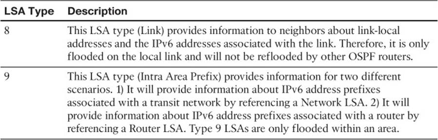
Table 15-5 Additional OSPF LSAs for OSPFv3
To verify the OSPFv3 routes that have been installed in the routing table, you use the show ipv6 route ospf command, as shown in Example 15-76. In this case, R1 only knows about an external OSPFv3 route, which is the default route, and two interarea routes (routes outside the area but still within the OSPFv3 domain).
Example 15-76 Displaying the OSPFv3 Routes in the Routing Table
R1#show ipv6 route ospf
IPv6 Routing Table - default - 10 entries
Codes: C - Connected, L - Local, S - Static, U - Per-user Static route
B - BGP, R - RIP, H - NHRP, I1 - ISIS L1
I2 - ISIS L2, IA - ISIS interarea, IS - ISIS summary, D - EIGRP
EX - EIGRP external, ND - ND Default, NDp - ND Prefix, DCE - Destination
NDr - Redirect, O - OSPF Intra, OI - OSPF Inter, OE1 - OSPF ext 1
OE2 - OSPF ext 2, ON1 - OSPF NSSA ext 1, ON2 - OSPF NSSA ext 2, l - LISP
OE2 ::/0 [110/1], tag 1
via FE80::C80A:13FF:FEB8:8, GigabitEthernet1/0
OI 2001:DB8:0:3::/64 [110/3]
via FE80::C80A:13FF:FEB8:8, GigabitEthernet1/0
OI 2001:DB8:0:23::/64 [110/2]
via FE80::C80A:13FF:FEB8:8, GigabitEthernet1/0
Use the show ipv6 interface interface_type interface_id command, as shown in Example 15-77, when troubleshooting OSPFv3 issues to verify whether the interface is listening to the multicast group addresses of FF02::5 (all OSPFv3 routers) and FF02::6 (OSPFv3 DR/BDR). You can also verify the MTU and whether there are any IPv6 ACLs applied to the interface that might be blocking OSPFv3 packets, or packets sourced from/destined to link-local addresses.
Example 15-77 Displaying the IPv6 Interface Parameters
R1#show ipv6 interface fastEthernet 3/0
FastEthernet3/0 is up, line protocol is up
IPv6 is enabled, link-local address is FE80::C809:13FF:FEB8:54
...output omitted...
Joined group address(es):
FF02::1
FF02::2
FF02::5
FF02::6
FF02::1:FF00:1
FF02::1:FFB8:54
MTU is 1500 bytes
ICMP error messages limited to one every 100 milliseconds
ICMP redirects are enabled
ICMP unreachables are sent
Input features: Access List IPsec
Output features: IPsec
Inbound access list TSHOOT_ACL
ND DAD is enabled, number of DAD attempts: 1
...output omitted...
OSPFv3 Trouble Tickets
This section presents various trouble tickets relating to the topics discussed earlier in the chapter. The purpose of these trouble tickets is to give a process that you can follow when troubleshooting in the real world or in an exam environment. All trouble tickets in this section are based on the topology depicted in Figure 15-13.
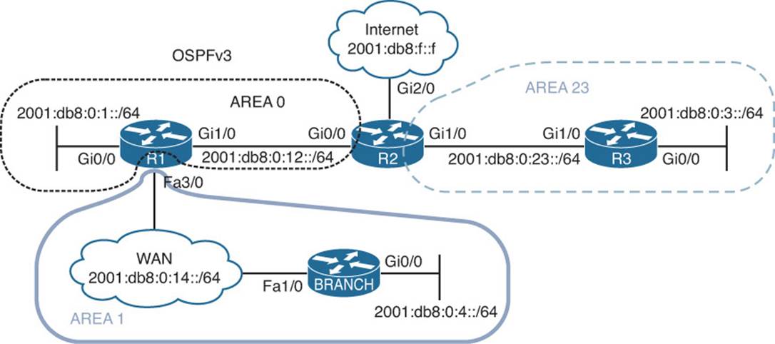
Figure 15-13 OSPFv3 Trouble Tickets Topology
Trouble Ticket 15-4
Problem: Recently, the network was updated to reduce the number of LSAs that would cross the WAN link from R1 to the Branch site. The only LSA that would be permitted is a Type 3 LSA about a default route. However, reports indicate that there are more Type 3 LSAs that are being sent from R1 to Branch.
You begin by reviewing the configuration change documents that were created when the change was implemented. You notice that the information is very vague. It only states that Area 1 was created as a totally stubby area. It does not indicate what changes were made to which devices and the commands that were used.
Your troubleshooting begins by verifying the problem with the show ipv6 route ospf command on Branch, as shown in Example 15-78. You confirm that there are more interarea routes than just the default interarea route.
Example 15-78 Displaying the IPv6 Routing Table on Branch
Branch#show ipv6 route ospf
IPv6 Routing Table - default - 10 entries
Codes: C - Connected, L - Local, S - Static, U - Per-user Static route
B - BGP, R - RIP, H - NHRP, I1 - ISIS L1
I2 - ISIS L2, IA - ISIS interarea, IS - ISIS summary, D - EIGRP
EX - EIGRP external, ND - ND Default, NDp - ND Prefix, DCE - Destination
NDr - Redirect, O - OSPF Intra, OI - OSPF Inter, OE1 - OSPF ext 1
OE2 - OSPF ext 2, ON1 - OSPF NSSA ext 1, ON2 - OSPF NSSA ext 2, l - LISP
OI ::/0 [110/2]
via FE80::C801:10FF:FE20:54, FastEthernet1/0
OI 2001:DB8:0:1::/64 [110/2]
via FE80::C801:10FF:FE20:54, FastEthernet1/0
OI 2001:DB8:0:3::/64 [110/4]
via FE80::C801:10FF:FE20:54, FastEthernet1/0
OI 2001:DB8:0:12::/64 [110/2]
via FE80::C801:10FF:FE20:54, FastEthernet1/0
OI 2001:DB8:0:23::/64 [110/3]
via FE80::C801:10FF:FE20:54, FastEthernet1/0
Next you want to confirm if Branch is configured as a stub for area 1. You issue the command show ipv6 ospf | include Area|stub as shown in Example 15-79 and confirm that it is.
Example 15-79 Verifying Whether Area 1 Is a Stub Area on Branch
Branch#show ipv6 ospf | include Area|stub
Number of areas in this router is 1. 0 normal 1 stub 0 nssa
Area 1
It is a stub area
You then issue the same command on R1, as shown in Example 15-80. The output indicates that area 1 is a stub area and that a default route is being injected into the area with a cost of 1.
Example 15-80 Verifying Whether Area 1 Is a Stub Area on R1
R1#show ipv6 ospf | include Area|stub
Number of areas in this router is 2. 1 normal 1 stub 0 nssa
Area BACKBONE(0)
Area 1
It is a stub area
Generates stub default route with cost 1
However, you realize that this output indicates that a stub area exists, not a totally stubby area. If it were a totally stubby area, it would also state no summary LSA in this area. To confirm this, you issue the command show run | section ipv6 router ospf on both R1 and Branch, as shown inExample 15-81. Reviewing the output, you notice that R1 is configured with area 1 stub and Branch is configured with area 1 stub no-summary. It appears that the commands were executed on the wrong routers.
Example 15-81 Verifying IPv6 Router OSPF Configuration on R1 and Branch
R1#show run | section ipv6 router ospf
ipv6 router ospf 1
router-id 1.1.1.1
area 1 stub
passive-interface GigabitEthernet0/0
Branch#show run | section ipv6 router ospf
ipv6 router ospf 1
router-id 4.4.4.4
area 1 stub no-summary
passive-interface default
no passive-interface FastEthernet1/0
To fix this issue, you issue the command area 1 stub no-summary on R1 and the commands no area 1 stub no-summary and area 1 stub on Branch. Once the change has been made, you issue the command show run | section ipv6 router ospf on both R1 and Branch to confirm the changes were made, as shown in Example 15-82.
Example 15-82 Verifying IPv6 Router OSPF Configuration on R1 and Branch After Change
R1#show run | section ipv6 router ospf
ipv6 router ospf 1
router-id 1.1.1.1
area 1 stub no-summary
passive-interface GigabitEthernet0/0
Branch#show run | section ipv6 router ospf
ipv6 router ospf 1
router-id 4.4.4.4
area 1 stub
passive-interface default
no passive-interface FastEthernet1/0
Next you issue the command show ipv6 ospf | include Area|stub on R1, as shown in Example 15-83, to verify that it states no summary LSA in this area, which means no Type 3. It does!
Example 15-83 Verifying Area 1 Is a Stub Area With No Summary LSAs On R1
R1#show ipv6 ospf | include Area|stub
Number of areas in this router is 2. 1 normal 1 stub 0 nssa
Area BACKBONE(0)
Area 1
It is a stub area, no summary LSA in this area
Generates stub default route with cost 1
The output of show ipv6 route ospf on Branch only contains the default route now. The issue is solved, as shown in Example 15-84.
Example 15-84 Verifying Branch Is Only Receiving a Default Route
Branch#show ipv6 route ospf
IPv6 Routing Table - default - 6 entries
Codes: C - Connected, L - Local, S - Static, U - Per-user Static route
B - BGP, R - RIP, H - NHRP, I1 - ISIS L1
I2 - ISIS L2, IA - ISIS interarea, IS - ISIS summary, D - EIGRP
EX - EIGRP external, ND - ND Default, NDp - ND Prefix, DCE - Destination
NDr - Redirect, O - OSPF Intra, OI - OSPF Inter, OE1 - OSPF ext 1
OE2 - OSPF ext 2, ON1 - OSPF NSSA ext 1, ON2 - OSPF NSSA ext 2, l - LISP
OI ::/0 [110/2]
via FE80::C801:10FF:FE20:54, FastEthernet1/0
Trouble Ticket 15-5
Problem: Branch users are complaining that they are unable to access any resources outside the Branch office.
You access Branch and issue the extended ping command as shown in Example 15-85 to test connectivity and connectivity fails.
Example 15-85 Testing Connectivity from Branch to a Remote Network
Branch#ping
Protocol [ip]: ipv6
Target IPv6 address: 2001:db8:0:1::1
Repeat count [5]:
Datagram size [100]:
Timeout in seconds [2]:
Extended commands? [no]: yes
Source address or interface: 2001:db8:0:4::4
UDP protocol? [no]:
Verbose? [no]:
Precedence [0]:
DSCP [0]:
Include hop by hop option? [no]:
Include destination option? [no]:
Sweep range of sizes? [no]:
Type escape sequence to abort.
Sending 5, 100-byte ICMP Echos to 2001:DB8:0:1::1, timeout is 2 seconds:
Packet sent with a source address of 2001:DB8:0:4::4
.....
Success rate is 0 percent (0/5)
You issue the show ipv6 route command on Branch and notice that there are only local and connected routes, as shown in Example 15-86.
Example 15-86 Verifying IPv6 Routes in a Routing Table
Branch#show ipv6 route
...output omitted...
C 2001:DB8:0:4::/64 [0/0]
via GigabitEthernet0/0, directly connected
L 2001:DB8:0:4::4/128 [0/0]
via GigabitEthernet0/0, receive
C 2001:DB8:0:14::/64 [0/0]
via FastEthernet1/0, directly connected
L 2001:DB8:0:14::4/128 [0/0]
via FastEthernet1/0, receive
L FF00::/8 [0/0]
via Null0, receive
You conclude that no routes are being learned from R1. Therefore, there must be a neighbor issue. To confirm, you issue the command show ipv6 ospf neighbor on Branch, and as you suspected, Example 15-87 confirms that Branch is not a neighbor with R1.
Example 15-87 Verifying IPv6 OSPF Neighbors
Branch#show ipv6 ospf neighbor
Branch#
You suspect that the Branch interface connected to R1 is not enabled for the OSPFv3 process. You issue the show ipv6 ospf interface brief command to verify whether the interface is participating in the process. In Example 15-88, the output indicates that Fast Ethernet 1/0 is participating in the OSPFv3 process.
Example 15-88 Verifying OSPFv3-Enabled Interfaces on Branch
Branch#show ipv6 ospf interface brief
Interface PID Area Intf ID Cost State Nbrs F/C
Gi0/0 1 1 3 1 DR 0/0
Fa1/0 1 1 4 1 BDR 1/1
You decide to shift your attention to R1 and check whether the interface connected to Branch is participating in the OSPFv3 process. R1 is using Fast Ethernet 3/0 to connect to Branch. Issuing the command show ipv6 ospf interface brief on R1, as shown in Example 15-89, reveals that Fa3/0 is participating in the OSPF process as well.
Example 15-89 Verifying OSPFv3-Enabled Interfaces on R1
R1#show ipv6 ospf interface brief
Interface PID Area Intf ID Cost State Nbrs F/C
Gi1/0 1 0 4 1 BDR 1/1
Gi0/0 1 0 3 1 DR 0/0
Fa3/0 1 1 6 1 DR 0/0
You revisit Branch and decide to issue the debug ipv6 ospf hello command to gather further information. The output displayed in Example 15-90 reveals that timers are mismatched from FE80::C801:10FF:FE20:54. You issue the show cdp neighbors detail command on Branch, as shown inExample 15-91, to confirm that R1 is using that link-local address. It is! Therefore, you conclude that the neighbor relationship is not formed because of mismatched timers.
Example 15-90 Using debug ipv6 ospf hello to Gather Further Information
Branch#debug ipv6 ospf hello
OSPFv3 hello events debugging is on for process 1, IPv6, Default vrf
Branch#
OSPFv3-1-IPv6 HELLO Fa1/0: Rcv hello from 1.1.1.1 area 1 from FE80::C801:10FF:FE20:54
interface ID 6
OSPFv3-1-IPv6 HELLO Fa1/0: Mismatched hello parameters from FE80::C801:10FF:FE20:54
OSPFv3-1-IPv6 HELLO Fa1/0: Dead R 40 C 120, Hello R 10 C 30
Branch#u all
All possible debugging has been turned off
Example 15-91 Using show cdp neighbors details to Verify Neighbor IPv6 Address
Branch#show cdp neighbors detail
-------------------------
Device ID: R1
Entry address(es):
IP address: 10.1.14.1
IPv6 address: 2001:DB8:0:14::1 (global unicast)
IPv6 address: FE80::C801:10FF:FE20:54 (link-local)
Platform: Cisco 7206VXR, Capabilities: Router
Interface: FastEthernet1/0, Port ID (outgoing port): FastEthernet3/0
...output omitted...
On R1, you issue the show ipv6 ospf interface fastethernet3/0 command, and on Branch you issue the show ipv6 ospf interface fastethernet1/0 command and use the spot-the-difference method, as shown in Example 15-92.
Example 15-92 Spotting the Difference Between R1 and Branch
R1#show ipv6 ospf interface fastEthernet 3/0
FastEthernet3/0 is up, line protocol is up
Link Local Address FE80::C801:10FF:FE20:54, Interface ID 6
Area 1, Process ID 1, Instance ID 0, Router ID 1.1.1.1
Network Type BROADCAST, Cost: 1
Transmit Delay is 1 sec, State DR, Priority 1
Designated Router (ID) 1.1.1.1, local address FE80::C801:10FF:FE20:54
No backup designated router on this network
Timer intervals configured, Hello 10, Dead 40, Wait 40, Retransmit 5
Hello due in 00:00:09
...output omitted...
Branch#show ipv6 ospf interface fastEthernet 1/0
FastEthernet1/0 is up, line protocol is up
Link Local Address FE80::C800:FFF:FE7C:1C, Interface ID 4
Area 1, Process ID 1, Instance ID 0, Router ID 4.4.4.4
Network Type NON_BROADCAST, Cost: 1
Transmit Delay is 1 sec, State DR, Priority 1
Designated Router (ID) 4.4.4.4, local address FE80::C800:FFF:FE7C:1C
No backup designated router on this network
Timer intervals configured, Hello 30, Dead 120, Wait 120, Retransmit 5
Hello due in 00:00:25
...output omitted...
You immediately notice that the hello and dead timers do not match. However, you remember that they can be configured manually or manipulated by changing the OSPF interface network type. Therefore, you check the network type and R1 is using BROADCAST (default for Ethernet interfaces), and Branch is using NON_BRAODCAST (not the default for Ethernet interfaces). Therefore, someone must have manually changed the network type on Branch.
You issue the command show run interface fastethernet 1/0 on Branch, as shown in Example 15-93, and confirm that the network type was manually changed with the ipv6 ospf network non-broadcast command.
Example 15-93 Verifying the Interface Configuration on Branch
Branch#show run interface fastEthernet 1/0
Building configuration...
Current configuration : 169 bytes
!
interface FastEthernet1/0
ip address 10.1.14.4 255.255.255.0
duplex full
ipv6 address 2001:DB8:0:14::4/64
ipv6 ospf 1 area 1
ipv6 ospf network non-broadcast
end
You remove this command with the no ipv6 ospf network non-broadcast command, which will change the network type back to the default of BROADCAST. Once that happens, a syslog message is generated indicating that a neighbor relationship is successfully formed between R1 and Branch:
%OSPFv3-5-ADJCHG: Process 1, Nbr 1.1.1.1 on FastEthernet1/0 from LOADING to FULL, Loading Done
You reissue the extended ping command on Branch, and it is successful, as shown in Example 15-94.
Example 15-94 Testing Connectivity from Branch to a Remote Network
Branch#ping
Protocol [ip]: ipv6
Target IPv6 address: 2001:db8:0:1::1
Repeat count [5]:
Datagram size [100]:
Timeout in seconds [2]:
Extended commands? [no]: yes
Source address or interface: 2001:db8:0:4::4
UDP protocol? [no]:
Verbose? [no]:
Precedence [0]:
DSCP [0]:
Include hop by hop option? [no]:
Include destination option? [no]:
Sweep range of sizes? [no]:
Type escape sequence to abort.
Sending 5, 100-byte ICMP Echos to 2001:DB8:0:1::1, timeout is 2 seconds:
Packet sent with a source address of 2001:DB8:0:4::4
!!!!!
Success rate is 100 percent (5/5), round-trip min/avg/max = 16/29/52 ms
Troubleshoot OSPFv3 Address Families
OSPFv3 address families (AFs) enable you to configure a single process that will support both IPv4 and IPv6. In addition, a single database is maintained for IPv4 and IPv6. However, adjacencies are established individually for each AF, and settings can be configured on an AF-by-AF basis.
In this section, you learn the commands that you can use to troubleshoot an OSPFv3 implementation that uses address families.
OSPFv3 Address Family Troubleshooting
Example 15-95 shows a sample OSPFv3 configuration with AFs. The OSPFv3 PID is 10 and is locally significant. Therefore, it does not have to match between neighbors. Any parameter configured under the main router OSPFv3 configuration mode will apply to all address families. In this example, the area 23 stub command was configured under the main router OSPFv3 configuration mode; therefore, area 23 will be a stub area for both IPv4 and IPv6 address families. Note that if there are conflicts between configurations in router OSPFv3 configuration mode and AF configuration mode, AF configuration mode wins. You still enable the OSPFv3 process on an interface-by-interface basis in interface configuration mode with the ospfv3 process_id {ipv4|ipv6} area area_id command. In addition, OSPFv3 interface parameters are still configured in interface configuration mode. However, remember that if you do not specify the AF (IPv4 or IPv6), the configured parameter applies to all address families. If you apply the configuration to the AF, it applies only to that AF. If a conflict exists, the AF configuration wins. Refer to the Gigabit Ethernet 0/0 configuration in Example 15-95. Notice that the hello interval is configured without an AF specified. Therefore, it applies to both IPv4 and IPv6. However, the hello interval is also configured for the IPv6 AF. Therefore, this configuration prevails for IPv6, and a hello interval of 10 is used; IPv4 uses the hello interval of 11.
Example 15-95 Sample OSPFv3 Configuration with Address Families
R2#show run | section router ospfv3
router ospfv3 10
area 23 stub
!
address-family ipv4 unicast
passive-interface default
no passive-interface GigabitEthernet0/0
no passive-interface GigabitEthernet1/0
default-information originate
router-id 2.2.2.2
exit-address-family
!
address-family ipv6 unicast
passive-interface default
no passive-interface GigabitEthernet0/0
no passive-interface GigabitEthernet1/0
default-information originate
router-id 22.22.22.22
exit-address-family
R2#show run int gig 1/0
interface GigabitEthernet1/0
ip address 10.1.23.2 255.255.255.0
ipv6 address 2001:DB8:0:23::2/64
ospfv3 10 ipv6 area 23
ospfv3 10 ipv4 area 23
end
R2#show run int gig 0/0
interface GigabitEthernet0/0
ip address 10.1.12.2 255.255.255.0
ipv6 address 2001:DB8:0:12::2/64
ospfv3 10 hello-interval 11
ospfv3 10 ipv6 area 0
ospfv3 10 ipv6 hello-interval 10
ospfv3 10 ipv4 area 0
end
With OSPFv3 AFs, you can still use the show ip protocols and show ipv6 protocols commands, as shown in Example 15-96, to verify the same information previously discussed in the chapter.
Example 15-96 Using show ip protocols and show ipv6 protocols
R2#show ip protocols
*** IP Routing is NSF aware ***
Routing Protocol is "ospfv3 10"
Outgoing update filter list for all interfaces is not set
Incoming update filter list for all interfaces is not set
Router ID 2.2.2.2
Area border and autonomous system boundary router
Number of areas: 1 normal, 1 stub, 0 nssa
Interfaces (Area 0):
GigabitEthernet0/0
Interfaces (Area 23):
GigabitEthernet1/0
Maximum path: 4
Routing Information Sources:
Gateway Distance Last Update
2.2.2.2 110 00:12:39
3.3.3.3 110 00:12:39
10.1.14.1 110 00:00:57
Distance: (default is 110)
R2#show ipv6 protocols
IPv6 Routing Protocol is "connected"
IPv6 Routing Protocol is "ND"
IPv6 Routing Protocol is "static"
IPv6 Routing Protocol is "ospf 10"
Router ID 22.22.22.22
Area border and autonomous system boundary router
Number of areas: 1 normal, 1 stub, 0 nssa
Interfaces (Area 0):
GigabitEthernet0/0
Interfaces (Area 23):
GigabitEthernet1/0
Redistribution:
None
The output of show ospfv3, as shown in Example 15-97, displays the same information you would find with the show ip ospf and show ipv6 ospf commands. Notice that the IPv4 AF is listed first followed by the IPv6 AF.
Example 15-97 Using show ospfv3 to Verify General OSPFv3 Parameters for AFs
R2#show ospfv3
OSPFv3 10 address-family ipv4
Router ID 2.2.2.2
Supports NSSA (compatible with RFC 3101)
Event-log enabled, Maximum number of events: 1000, Mode: cyclic
It is an area border and autonomous system boundary router
Redistributing External Routes from,
Originate Default Route
Router is not originating router-LSAs with maximum metric
Initial SPF schedule delay 5000 msecs
Minimum hold time between two consecutive SPFs 10000 msecs
Maximum wait time between two consecutive SPFs 10000 msecs
Minimum LSA interval 5 secs
Minimum LSA arrival 1000 msecs
LSA group pacing timer 240 secs
Interface flood pacing timer 33 msecs
Retransmission pacing timer 66 msecs
Retransmission limit dc 24 non-dc 24
Number of external LSA 1. Checksum Sum 0x0013EB
Number of areas in this router is 2. 1 normal 1 stub 0 nssa
Graceful restart helper support enabled
Reference bandwidth unit is 100 mbps
RFC1583 compatibility enabled
Area BACKBONE(0)
Number of interfaces in this area is 1
SPF algorithm executed 13 times
Number of LSA 11. Checksum Sum 0x05A71D
Number of DCbitless LSA 0
Number of indication LSA 0
Number of DoNotAge LSA 0
Flood list length 0
Area 23
Number of interfaces in this area is 1
It is a stub area
Generates stub default route with cost 1
SPF algorithm executed 8 times
Number of LSA 12. Checksum Sum 0x064322
Number of DCbitless LSA 0
Number of indication LSA 0
Number of DoNotAge LSA 0
Flood list length 0
OSPFv3 10 address-family ipv6
Router ID 22.22.22.22
Supports NSSA (compatible with RFC 3101)
Event-log enabled, Maximum number of events: 1000, Mode: cyclic
It is an area border and autonomous system boundary router
Originate Default Route
Router is not originating router-LSAs with maximum metric
Initial SPF schedule delay 5000 msecs
Minimum hold time between two consecutive SPFs 10000 msecs
Maximum wait time between two consecutive SPFs 10000 msecs
Minimum LSA interval 5 secs
Minimum LSA arrival 1000 msecs
LSA group pacing timer 240 secs
Interface flood pacing timer 33 msecs
Retransmission pacing timer 66 msecs
Retransmission limit dc 24 non-dc 24
Number of external LSA 1. Checksum Sum 0x00B8F5
Number of areas in this router is 2. 1 normal 1 stub 0 nssa
Graceful restart helper support enabled
Reference bandwidth unit is 100 mbps
RFC1583 compatibility enabled
Area BACKBONE(0)
Number of interfaces in this area is 1
SPF algorithm executed 13 times
Number of LSA 11. Checksum Sum 0x0422C7
Number of DCbitless LSA 0
Number of indication LSA 0
Number of DoNotAge LSA 0
Flood list length 0
Area 23
Number of interfaces in this area is 1
It is a stub area
Generates stub default route with cost 1
SPF algorithm executed 11 times
Number of LSA 12. Checksum Sum 0x0591F5
Number of DCbitless LSA 0
Number of indication LSA 0
Number of DoNotAge LSA 0
Flood list length 0
Using the command show ospfv3 interface brief command will display the interfaces participating in the OSPFv3 process for each AF, as shown in Example 15-98. Notice the added column that indicates which AF the interface is participating in.
Example 15-98 Using show ospfv3 interface brief to Verify OSPFv3 Interfaces
R2#show ospfv3 interface brief
Interface PID Area AF Cost State Nbrs F/C
Gi0/0 10 0 ipv4 1 BDR 1/1
Gi1/0 10 23 ipv4 1 BDR 1/1
Gi0/0 10 0 ipv6 1 BDR 1/1
Gi1/0 10 23 ipv6 1 BDR 1/1
The show ospfv3 interface command enables you to review detailed information about the interface configurations, as shown earlier in the chapter. Example 15-99 displays the IPv4 AF information at the top and the IPv6 AF information at the bottom.
Example 15-99 Using show ospfv3 interface to Verify Details of OSPFv3 Interfaces
R2#show ospfv3 interface gigabitEthernet 1/0
GigabitEthernet1/0 is up, line protocol is up
Link Local Address FE80::C802:10FF:FE20:1C, Interface ID 4
Internet Address 10.1.23.2/24
Area 23, Process ID 10, Instance ID 64, Router ID 2.2.2.2
Network Type BROADCAST, Cost: 1
Transmit Delay is 1 sec, State BDR, Priority 1
Designated Router (ID) 3.3.3.3, local address FE80::C804:10FF:FE74:1C
Backup Designated router (ID) 2.2.2.2, local address FE80::C802:10FF:FE20:1C
Timer intervals configured, Hello 10, Dead 40, Wait 40, Retransmit 5
Hello due in 00:00:02
Graceful restart helper support enabled
Index 1/1/2, flood queue length 0
Next 0x0(0)/0x0(0)/0x0(0)
Last flood scan length is 4, maximum is 5
Last flood scan time is 4 msec, maximum is 4 msec
Neighbor Count is 1, Adjacent neighbor count is 1
Adjacent with neighbor 3.3.3.3 (Designated Router)
Suppress hello for 0 neighbor(s)
GigabitEthernet1/0 is up, line protocol is up
Link Local Address FE80::C802:10FF:FE20:1C, Interface ID 4
Area 23, Process ID 10, Instance ID 0, Router ID 22.22.22.22
Network Type BROADCAST, Cost: 1
Transmit Delay is 1 sec, State BDR, Priority 1
Designated Router (ID) 33.33.33.33, local address FE80::C804:10FF:FE74:1C
Backup Designated router (ID) 22.22.22.22, local address FE80::C802:10FF:FE20:1C
Timer intervals configured, Hello 10, Dead 40, Wait 40, Retransmit 5
Hello due in 00:00:03
Graceful restart helper support enabled
Index 1/1/2, flood queue length 0
Next 0x0(0)/0x0(0)/0x0(0)
Last flood scan length is 1, maximum is 4
Last flood scan time is 0 msec, maximum is 4 msec
Neighbor Count is 1, Adjacent neighbor count is 1
Adjacent with neighbor 33.33.33.33 (Designated Router)
Suppress hello for 0 neighbor(s)
To verify the neighbor relationships that have been formed for each AF, issue the command show ospfv3 neighbor, as shown in Example 15-100. Again, the output is presenting the same information as discussed earlier in the chapter, except this time there are different sections for each AF.
Example 15-100 Using show ospfv3 neighbor to Verify OSPFv3 Neighbors
R2#show ospfv3 neighbor
OSPFv3 10 address-family ipv4 (router-id 2.2.2.2)
Neighbor ID Pri State Dead Time Interface ID Interface
10.1.14.1 1 FULL/DR 00:00:34 4 GigabitEthernet0/0
3.3.3.3 1 FULL/DR 00:00:36 4 GigabitEthernet1/0
OSPFv3 10 address-family ipv6 (router-id 22.22.22.22)
Neighbor ID Pri State Dead Time Interface ID Interface
10.1.14.1 1 FULL/DR 00:00:31 4 GigabitEthernet0/0
33.33.33.33 1 FULL/DR 00:00:34 4 GigabitEthernet1/0
To verify the information in the LSDB, you issue the command show ospfv3 database. When using AFs, the OSPFv3 database contains LSAs for both IPv4 and IPv6 as shown in Example 15-101.
Example 15-101 Verifying the LSDB with show ospfv3 database
R2#show ospfv3 database
OSPFv3 10 address-family ipv4 (router-id 2.2.2.2)
Router Link States (Area 0)
ADV Router Age Seq# Fragment ID Link count Bits
2.2.2.2 1456 0x80000008 0 1 B E
10.1.14.1 1457 0x80000007 0 1 B
Net Link States (Area 0)
ADV Router Age Seq# Link ID Rtr count
10.1.14.1 1453 0x80000003 4 2
Inter Area Prefix Link States (Area 0)
ADV Router Age Seq# Prefix
2.2.2.2 1618 0x80000003 10.1.23.0/24
2.2.2.2 94 0x80000002 10.1.3.0/24
10.1.14.1 1599 0x80000002 10.1.14.0/24
10.1.14.1 1599 0x80000002 10.1.4.0/24
Link (Type-8) Link States (Area 0)
ADV Router Age Seq# Link ID Interface
2.2.2.2 1618 0x80000003 3 Gi0/0
10.1.14.1 1599 0x80000002 4 Gi0/0
Intra Area Prefix Link States (Area 0)
ADV Router Age Seq# Link ID Ref-lstype Ref-LSID
10.1.14.1 1457 0x80000007 0 0x2001 0
10.1.14.1 1453 0x80000003 4096 0x2002 4
Router Link States (Area 23)
ADV Router Age Seq# Fragment ID Link count Bits
2.2.2.2 94 0x80000007 0 1 B
3.3.3.3 248 0x80000009 0 1 None
Net Link States (Area 23)
ADV Router Age Seq# Link ID Rtr count
3.3.3.3 248 0x80000007 4 2
Inter Area Prefix Link States (Area 23)
ADV Router Age Seq# Prefix
2.2.2.2 1869 0x80000002 0.0.0.0/0
2.2.2.2 1442 0x80000001 10.1.1.0/24
2.2.2.2 1442 0x80000001 10.1.12.0/24
2.2.2.2 1442 0x80000001 10.1.4.0/24
2.2.2.2 1442 0x80000001 10.1.14.0/24
Link (Type-8) Link States (Area 23)
ADV Router Age Seq# Link ID Interface
2.2.2.2 1618 0x80000004 4 Gi1/0
3.3.3.3 1758 0x80000004 4 Gi1/0
Intra Area Prefix Link States (Area 23)
ADV Router Age Seq# Link ID Ref-lstype Ref-LSID
3.3.3.3 248 0x80000008 0 0x2001 0
3.3.3.3 248 0x80000007 4096 0x2002 4
Type-5 AS External Link States
ADV Router Age Seq# Prefix
2.2.2.2 1618 0x80000003 0.0.0.0/0
OSPFv3 10 address-family ipv6 (router-id 22.22.22.22)
Router Link States (Area 0)
ADV Router Age Seq# Fragment ID Link count Bits
10.1.14.1 330 0x80000007 0 1 B
22.22.22.22 198 0x8000000A 0 1 B E
Net Link States (Area 0)
ADV Router Age Seq# Link ID Rtr count
10.1.14.1 330 0x80000004 4 2
Inter Area Prefix Link States (Area 0)
ADV Router Age Seq# Prefix
10.1.14.1 1598 0x80000002 2001:DB8:0:14::/64
10.1.14.1 1598 0x80000002 2001:DB8:0:4::/64
22.22.22.22 198 0x80000002 2001:DB8:0:3::/64
22.22.22.22 198 0x80000002 2001:DB8:0:23::/64
Link (Type-8) Link States (Area 0)
ADV Router Age Seq# Link ID Interface
10.1.14.1 1598 0x80000002 4 Gi0/0
22.22.22.22 1446 0x80000003 3 Gi0/0
Intra Area Prefix Link States (Area 0)
ADV Router Age Seq# Link ID Ref-lstype Ref-LSID
10.1.14.1 330 0x80000006 0 0x2001 0
10.1.14.1 330 0x80000004 4096 0x2002 4
Router Link States (Area 23)
ADV Router Age Seq# Fragment ID Link count Bits
22.22.22.22 198 0x8000000A 0 1 B
33.33.33.33 237 0x80000008 0 1 None
Net Link States (Area 23)
ADV Router Age Seq# Link ID Rtr count
33.33.33.33 237 0x80000007 4 2
Inter Area Prefix Link States (Area 23)
ADV Router Age Seq# Prefix
22.22.22.22 198 0x80000005 2001:DB8:0:12::/64
22.22.22.22 1961 0x80000002 ::/0
22.22.22.22 198 0x80000002 2001:DB8:0:1::/64
22.22.22.22 198 0x80000002 2001:DB8:0:4::/64
22.22.22.22 198 0x80000002 2001:DB8:0:14::/64
Link (Type-8) Link States (Area 23)
ADV Router Age Seq# Link ID Interface
22.22.22.22 1446 0x80000004 4 Gi1/0
33.33.33.33 1713 0x80000004 4 Gi1/0
Intra Area Prefix Link States (Area 23)
ADV Router Age Seq# Link ID Ref-lstype Ref-LSID
33.33.33.33 237 0x8000000A 0 0x2001 0
33.33.33.33 237 0x80000007 4096 0x2002 4
Type-5 AS External Link States
ADV Router Age Seq# Prefix
22.22.22.22 1446 0x80000003 ::/0
Keep in mind when troubleshooting OSPFv3 AFs that both OSPF for IPv4 and OSPF for IPv6 use IPv6 to exchange routing information. Therefore, IPv6 unicast routing must be enabled on the router. Also, classic OSPFv2 and the OSPFv3 AFs are not compatible. Therefore, a router using OSPFv3 AFs for IPv4 will not peer with a router using the classic OSPFv2 configuration for IPv4 because they are not compatible.
To verify the IPv4 OSPFv3 entries in the routing table, you can use the show ip route ospfv3 command. To verify the IPv6 OSPFv3 entries in the routing table, you can use the show ipv6 route ospf command.
If you need to perform any debugging for OSPFv3, you can issue the debug ospfv3 command followed by what you want to debug, such as events, packets, hellos, or adj. This will turn on the debug for all AFs. If you want to only turn it on for a specific AF, you need to include the AF in the command (for example debug ospfv3 ipv6 hello). In the command, ipv6 is referring to the AF.
OSPFv3 AF Trouble Tickets
This section presents various trouble tickets relating to the topics discussed earlier in the chapter. The purpose of these trouble tickets is to give a process that you can follow when troubleshooting in the real world or in an exam environment. All trouble tickets in this section are based on the topology depicted in Figure 15-14.
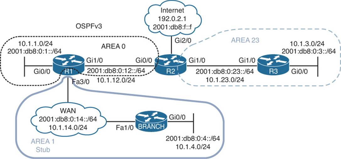
Figure 15-14 OSPFv3 AF Trouble Tickets Topology
Trouble Ticket 15-6
Problem: Users in Branch have indicated that they are not able to access any IPv6-enabled resources on the Internet but they can access IPv4-enabled resources.
An extended ping issued on Branch to the destination 2001:db8:f::f confirms the issue as shown in Example 15-102. In addition, you ping 192.0.2.1 and it is successful confirming connectivity to IPv4-enabled resources.
Example 15-102 Verifying Connectivity
Branch#ping
Protocol [ip]: ipv6
Target IPv6 address: 2001:db8:f::f
Repeat count [5]:
Datagram size [100]:
Timeout in seconds [2]:
Extended commands? [no]: yes
Source address or interface: 2001:db8:0:4::4
UDP protocol? [no]:
Verbose? [no]:
Precedence [0]:
DSCP [0]:
Include hop by hop option? [no]:
Include destination option? [no]:
Sweep range of sizes? [no]:
Type escape sequence to abort.
Sending 5, 100-byte ICMP Echos to 2001:DB8:f::f, timeout is 2 seconds:
Packet sent with a source address of 2001:DB8:0:4::4
UUUUU
Success rate is 0 percent (0/5)
Branch#ping 192.0.2.1 source 10.1.4.4
Type escape sequence to abort.
Sending 5, 100-byte ICMP Echos to 192.0.2.1, timeout is 2 seconds:
Packet sent with a source address of 10.1.4.4
!!!!!
Success rate is 100 percent (5/5), round-trip min/avg/max = 80/112/152 ms
On the Branch router, you issue the command show ipv6 route 2001:db8:f::f, and Example 15-103 indicates that the Branch router has a default route that can be used to reach the IPv6 address. This explains why the ping returned UUUUU. It indicates that the destination is not reachable by some other router. But which router is returning this message?
Example 15-103 Verifying Routes in the IPv6 Routing Table
Branch#show ipv6 route 2001:db8:f::f
Routing entry for ::/0
Known via "ospf 1", distance 110, metric 2, type inter area
Route count is 1/1, share count 0
Routing paths:
FE80::C801:10FF:FE20:54, FastEthernet1/0
Last updated 00:07:28 ago
To verify this, you issue a trace to see where it fails. Example 15-104 displays the results of the command traceroute 2001:db8:f::f. The trace indicates that R1 is returning the destination unreachable message.
Example 15-104 Tracing the Path
Branch#traceroute 2001:db8:f::f
Type escape sequence to abort.
Tracing the route to 2001:DB8:F::F
1 2001:DB8:0:14::1 !U !U !U
You visit R1 and issue the show ipv6 route 2001:db8:f::f command, as shown in Example 15-105, and confirm that there is no route to reach that IPv6 address. Why would Branch have a default route but not R1? Reviewing the network diagram shows that area 1 is a stub area. Therefore, R1 is generating a default route and injecting it into the stub area. This is why the default route on Branch, as shown in Example 15-103, is of type interarea and not external.
Example 15-105 Verifying Routes on R1
R1#show ipv6 route 2001:db8:f::f
% Route not found
It seems that R2 might not be generating a default route when it should be. You access R2 and issue the show ospfv3 ipv6 command, as shown in Example 15-106, and confirm that it is not an ASBR, when it should be if it is generating a default route.
Example 15-106 Verifying OSPFv3 Parameters on R2
R2#show ospfv3 ipv6
OSPFv3 10 address-family ipv6
Router ID 22.22.22.22
Supports NSSA (compatible with RFC 3101)
Event-log enabled, Maximum number of events: 1000, Mode: cyclic
It is an area border router
Router is not originating router-LSAs with maximum metric
Initial SPF schedule delay 5000 msecs
Minimum hold time between two consecutive SPFs 10000 msecs
Maximum wait time between two consecutive SPFs 10000 msecs
Minimum LSA interval 5 secs
Minimum LSA arrival 1000 msecs
LSA group pacing timer 240 secs
Interface flood pacing timer 33 msecs
Retransmission pacing timer 66 msecs
Retransmission limit dc 24 non-dc 24
Number of external LSA 0. Checksum Sum 0x000000
Number of areas in this router is 2. 1 normal 1 stub 0 nssa
Graceful restart helper support enabled
Reference bandwidth unit is 100 mbps
RFC1583 compatibility enabled
Area BACKBONE(0)
Number of interfaces in this area is 1
SPF algorithm executed 14 times
Number of LSA 11. Checksum Sum 0x04EDE6
Number of DCbitless LSA 0
Number of indication LSA 0
Number of DoNotAge LSA 0
Flood list length 0
Area 23
Number of interfaces in this area is 1
It is a stub area
Generates stub default route with cost 1
SPF algorithm executed 11 times
Number of LSA 12. Checksum Sum 0x06610D
Number of DCbitless LSA 0
Number of indication LSA 0
Number of DoNotAge LSA 0
Flood list length 0
Next you issue the command show run | section router ospfv3. The output in Example 15-107 confirms that the default-information originate command is missing from IPv6 AF configuration mode. It is only configured under IPv4 AF configuration mode.
Example 15-107 Verifying OSPFv3 Configuration on R2
R2#show run | section router ospfv3
router ospfv3 10
area 23 stub
!
address-family ipv4 unicast
passive-interface default
no passive-interface GigabitEthernet0/0
no passive-interface GigabitEthernet1/0
default-information originate
router-id 2.2.2.2
exit-address-family
!
address-family ipv6 unicast
passive-interface default
no passive-interface GigabitEthernet0/0
no passive-interface GigabitEthernet1/0
router-id 22.22.22.22
exit-address-family
You add the default-information originate command to IPv6 AF configuration mode and reissue the extended IPv6 ping on Branch, as shown in Example 15-108. The ping is successful.
Example 15-108 Successful Ping to IPv6 Internet Resources
Branch#ping
Protocol [ip]: ipv6
Target IPv6 address: 2001:db8:f::f
Repeat count [5]:
Datagram size [100]:
Timeout in seconds [2]:
Extended commands? [no]: yes
Source address or interface: 2001:db8:0:4::4
UDP protocol? [no]:
Verbose? [no]:
Precedence [0]:
DSCP [0]:
Include hop by hop option? [no]:
Include destination option? [no]:
Sweep range of sizes? [no]:
Type escape sequence to abort.
Sending 5, 100-byte ICMP Echos to 2001:DB8:F::F, timeout is 2 seconds:
Packet sent with a source address of 2001:DB8:0:4::4
!!!!!
Success rate is 100 percent (5/5), round-trip min/avg/max = 88/113/148 ms
Exam Preparation Tasks
As mentioned in the section “How to Use This Book” in the Introduction, you have a couple of choices for exam preparation: the exercises here; Chapter 22, “Final Preparation;” and the exam simulation questions on the CD-ROM.
Review All Key Topics
Review the most important topics in this chapter, noted with the Key Topic icon in the outer margin of the page. Table 15-6 lists a reference of these key topics and the page numbers on which each is found.
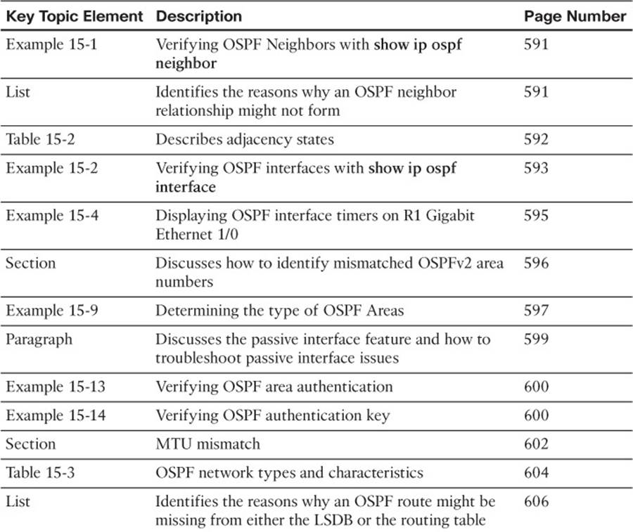
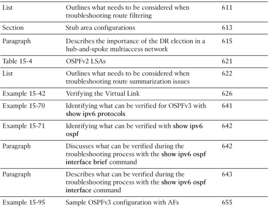
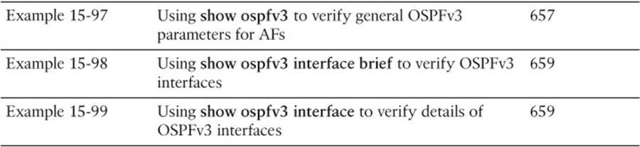
Table 15-6 Key Topics for Chapter 15
Define Key Terms
Define the following key terms from this chapter and check your answers in the glossary:
OSPF interface table
OSPF neighbor table
OSPF link-state database
link-state advertisement (LSA)
Dijkstra shortest path first (SPF) algorithm
OSPF area
virtual link
OSPF Area Border Router (ABR)
OSPF Autonomous System Boundary Router (ASBR)
OSPFv3
address families
designated router
backup designated router
stub area
totally stubby area
NSSA
totally NSSA
Complete Tables and Lists from Memory
Print a copy of Appendix C, “Memory Tables,” (found on the disc), or at least the section for this chapter, and complete the tables and lists from memory. Appendix D, “Memory Tables Answer Key,” also on the disc, includes completed tables and lists to check your work.
Command Reference to Check Your Memory
This section includes the most important show and debug commands covered in this chapter. It might not be necessary to memorize the complete syntax of every command, but you should be able to remember the basic keywords that are needed.
To test your memory of the commands, cover the right side of Table 15-7 with a piece of paper, read the description on the left side, and then see how much of the command you can remember.
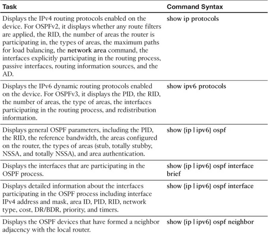
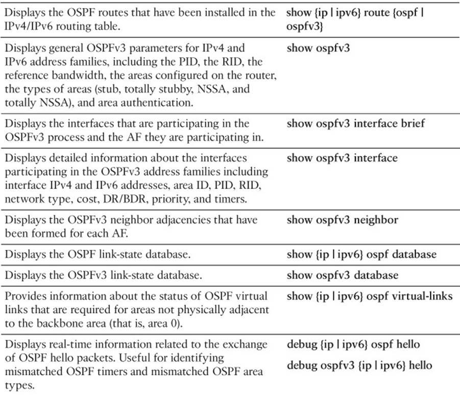
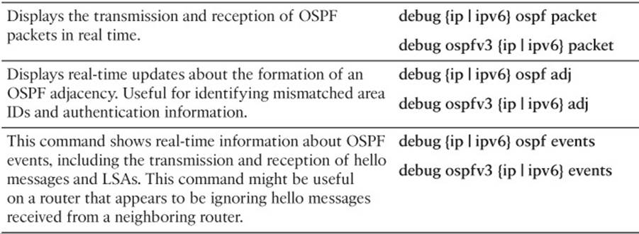
Table 15-7 show and debug commands
The 300-135 TSHOOT exam focuses on practical, hands-on skills that are used by a networking professional. Therefore, you should be able to identify the commands needed to successfully troubleshoot the different issues outlined in this chapter.
All materials on the site are licensed Creative Commons Attribution-Sharealike 3.0 Unported CC BY-SA 3.0 & GNU Free Documentation License (GFDL)
If you are the copyright holder of any material contained on our site and intend to remove it, please contact our site administrator for approval.
© 2016-2026 All site design rights belong to S.Y.A.