CCNP Routing and Switching TSHOOT 300-135 Official Cert Guide (2015)
Part V. Final Preparation
Chapter 21. Additional Trouble Tickets
This chapter covers the following topics:
In each Trouble Ticket you are presented with a collection of show and debug commands output and challenged to resolve a series of misconfigurations. Suggested solutions are also provided.
![]() Trouble Ticket 1: This section presents you with a trouble ticket addressing a network experiencing STP issues.
Trouble Ticket 1: This section presents you with a trouble ticket addressing a network experiencing STP issues.
![]() Trouble Ticket 2: This section presents you with a trouble ticket addressing a network experiencing HSRP issues.
Trouble Ticket 2: This section presents you with a trouble ticket addressing a network experiencing HSRP issues.
![]() Trouble Ticket 3: This section presents you with a trouble ticket addressing a network experiencing EIGRP issues.
Trouble Ticket 3: This section presents you with a trouble ticket addressing a network experiencing EIGRP issues.
![]() Trouble Ticket 4: This section presents you with a trouble ticket addressing a network experiencing OSPF issues.
Trouble Ticket 4: This section presents you with a trouble ticket addressing a network experiencing OSPF issues.
![]() Trouble Ticket 5: This section presents you with a trouble ticket addressing a network experiencing redistribution issues.
Trouble Ticket 5: This section presents you with a trouble ticket addressing a network experiencing redistribution issues.
![]() Trouble Ticket 6: This section presents you with a trouble ticket addressing a network experiencing BGP issues.
Trouble Ticket 6: This section presents you with a trouble ticket addressing a network experiencing BGP issues.
![]() Trouble Ticket 7: This section presents you with a trouble ticket addressing a network experiencing management access issues.
Trouble Ticket 7: This section presents you with a trouble ticket addressing a network experiencing management access issues.
![]() Trouble Ticket 8: This section presents you with a trouble ticket addressing a network experiencing NAT issues.
Trouble Ticket 8: This section presents you with a trouble ticket addressing a network experiencing NAT issues.
![]() Trouble Ticket 9: This section presents you with a trouble ticket addressing a network experiencing OSPFv3 issues.
Trouble Ticket 9: This section presents you with a trouble ticket addressing a network experiencing OSPFv3 issues.
![]() Trouble Ticket 10: This section presents you with a trouble ticket addressing a network experiencing RIPng issues.
Trouble Ticket 10: This section presents you with a trouble ticket addressing a network experiencing RIPng issues.
Troubleshooting routed and switched networks is an art. The more time you spend troubleshooting, the better you will become. However, many of us do not have the opportunity to troubleshoot on a regular basis or experience many of the issues that may arise in routed and switched networks. Therefore, the more issues you can see samples of, the better.
This chapter is dedicated to showing you additional trouble tickets and the various approaches that you can take to solve the problems that are presented. Always remember that the right way to troubleshoot is the way that solves the problem for you. You and I and the person next to you will all have different methods and approaches to troubleshooting. What works for one might not work for the other. Someone with years of experience will have a vast knowledge base in their head that they can call upon for help while the novice will have to do more research or ask for assistance at times. However, no matter what, we all have the same goal. Solve the problem! Let’s see how the following issues presented in this chapter could be solved.
Introduction
All trouble tickets begin with a problem report and a network topology diagram. Some of the trouble tickets provide you with baseline data, and all the trouble tickets offer output from appropriate verification commands (for example, show or debug commands) that you can examine.
After you hypothesize the underlying cause of the network issue and formulate a solution, you can check the suggested solution comments to confirm your hypothesis. Realize, however, that some trouble tickets might be resolvable by more than one method. Therefore, your solution might be different from the suggested solution.
Trouble Ticket 1
You receive the following trouble ticket:
Users on network 192.168.1.0/24 are experiencing latency or no connectivity when attempting to reach network 10.1.2.0/24. It appears to be STP related.
This trouble ticket references the topology shown in Figure 21-1.
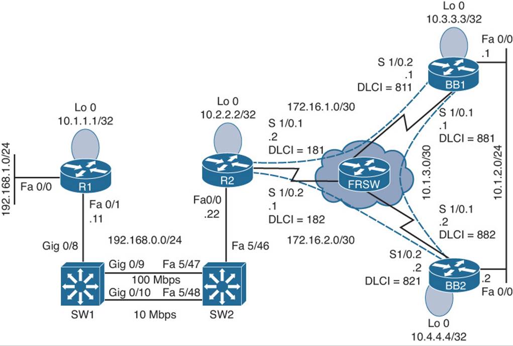
Figure 21-1 Topology for Trouble Ticket 1
As you follow the path of the traffic from network 192.168.1.0/24 to 10.1.2.0/24, you notice high port utilization levels on switches SW1 and SW2. Therefore, you decide to investigate these switches further.
You have previously issued show commands on these switches as part of your baseline collection process. A selection of the show command output is presented in Examples 21-1 and 21-2.
Example 21-1 Baseline show Output from Switch SW1
SW1#show spanning-tree vlan 1
VLAN0001
Spanning tree enabled protocol ieee
Root ID Priority 32768
Address 0009.122e.4181
Cost 19
Port 9 (GigabitEthernet0/9)
Hello Time 2 sec Max Age 20 sec Forward Delay 15 sec
Bridge ID Priority 32769 (priority 32768 sys-id-ext 1)
Address 000d.28e4.7c80
Hello Time 2 sec Max Age 20 sec Forward Delay 15 sec
Aging Time 300
Interface Role Sts Cost Prio.Nbr Type
-----------------------------------------------------------------------------------
Gi0/8 Desg FWD 19 128.8 P2p
Gi0/9 Root FWD 19 128.9 P2p
Gi0/10 Altn BLK 100 128.10 Shr
SW1#show spanning-tree summary
Switch is in pvst mode
Root bridge for: none
Extended system ID is enabled
Portfast Default is disabled
PortFast BPDU Guard Default is disabled
Portfast BPDU Filter Default is disabled
Loopguard Default is disabled
EtherChannel misconfig guard is enabled
UplinkFast is disabled
BackboneFast is disabled
Configured Pathcost method used is short
Name Blocking Listening Learning Forwarding STP Active
-----------------------------------------------------------------------------
VLAN0001 1 0 0 2 3
-----------------------------------------------------------------------------
1 vlan 1 0 0 2 3
SW1#show spanning-tree interface gig 0/10 detail
Port 10 (GigabitEthernet0/10) of VLAN0001 is alternate blocking
Port path cost 100, Port priority 128, Port Identifier 128.10.
Designated root has priority 32768, address 0009.122e.4181
Designated bridge has priority 32768, address 0009.122e.4181
Designated port id is 128.304, designated path cost 0
Timers: message age 1, forward delay 0, hold 0
Number of transitions to forwarding state: 0
Link type is shared by default
BPDU: sent 1, received 276
Example 21-2 Baseline show Output from Switch SW2
SW2#show spanning-tree vlan 1
VLAN0001
Spanning tree enabled protocol ieee
Root ID Priority 32768
Address 0009.122e.4181
This bridge is the root
Hello Time 2 sec Max Age 20 sec Forward Delay 15 sec
Bridge ID Priority 32768
Address 0009.122e.4181
Hello Time 2 sec Max Age 20 sec Forward Delay 15 sec
Aging Time 300
Interface Role Sts Cost Prio.Nbr Type
-----------------------------------------------------------------------------------
Fa5/46 Desg FWD 19 128.302 Shr
Fa5/47 Desg FWD 19 128.303 P2p
Fa5/48 Desg FWD 100 128.304 Shr
When you connect to the console of switch SW1, you receive the console messages displayed in Example 21-3.
Example 21-3 Console Messages on Switch SW1
SW1#
00:15:45: %SW_MATM-4-MACFLAP_NOTIF: Host 0009.b7fa.d1e1 in vlan 1 is flapping
between port Gi0/8 and port Gi0/9
SW1#
00:16:35: %SW_MATM-4-MACFLAP_NOTIF: Host 0009.b7fa.d1e1 in vlan 1 is flapping
between port Gi0/8 and port Gi0/9
SW1#
00:16:37: %SW_MATM-4-MACFLAP_NOTIF: Host c001.0e8c.0000 in vlan 1 is flapping
between port Gi0/9 and port Gi0/10
SW1#
00:16:41: %SW_MATM-4-MACFLAP_NOTIF: Host 0009.b7fa.d1e1 in vlan 1 is flapping
between port Gi0/8 and port Gi0/9
You also issue the show spanning-tree vlan 1 command on switches SW1 and SW2, as shown in Examples 21-4 and 21-5.
Example 21-4 show spanning-tree vlan 1 Command Output on Switch SW1
SW1#show spanning-tree vlan 1
Spanning tree instance(s) for vlan 1 does not exist.
Example 21-5 show spanning-tree vlan 1 Command Output on Switch SW2
SW2#show spanning-tree vlan 1
Spanning tree instance(s) for vlan 1 does not exist.
Take a moment to look through the baseline information, the topology, and the show command output. Then hypothesize the underlying cause for the connectivity issue reported in the trouble ticket. Finally, on a separate sheet of paper, write out a proposed action plan for resolving the reported issue.
Suggested Solution
The %SW_MATM-4-MACFLAP_NOTIF console message appearing on switch SW1 indicates that the MAC address in the MAC address table of switch SW1 is flapping between a couple of ports. This is a MAC address table corruption issue that is usually caused by STP not functioning correctly.
This suspicion is confirmed from the output in the show spanning-tree vlan 1 command, issued on switches SW1 and SW2, which indicates that there is no STP instance for VLAN 1 on either switch. Therefore, as a solution, STP should be enabled for VLAN 1 on both switches, which is depicted in Examples 21-6 and 21-7.
Example 21-6 Enabling STP for VLAN 1 on Switch SW1
SW1#conf term
Enter configuration commands, one per line. End with CNTL/Z.
SW1(config)#spanning-tree vlan 1
SW1(config)#end
Example 21-7 Enabling STP for VLAN 1 on Switch SW2
SW2#conf term
Enter configuration commands, one per line. End with CNTL/Z.
SW2(config)#spanning-tree vlan 1
SW2(config)#end
After giving STP sufficient time to converge, after enabling STP for VLAN 1, the show spanning-tree vlan 1 command is once again issued on switches SW1 and SW2, as illustrated in Examples 21-8 and 21-9. The output in these examples confirms that STP is now functioning correctly.
Example 21-8 Checking the STP Status for VLAN 1 on Switch SW1
SW1#show spanning-tree vlan 1
...OUTPUT OMITTED...
Interface Role Sts Cost Prio.Nbr Type
-----------------------------------------------------------------------------------
Gi0/8 Desg FWD 19 128.8 P2p
Gi0/9 Root FWD 19 128.9 P2p
Gi0/10 Altn BLK 100 128.10 Shr
Example 21-9 Checking the STP Status for VLAN 1 on Switch SW2
SW2#show spanning-tree vlan 1
...OUTPUT OMITTED...
Interface Role Sts Cost Prio.Nbr Type
-----------------------------------------------------------------------------------
Fa5/46 Desg FWD 19 128.302 Shr
Fa5/47 Desg FWD 19 128.303 P2p
Fa5/48 Desg FWD 100 128.304 Shr
Trouble Ticket 2
You receive the following trouble ticket:
A new network technician configured HSRP on routers BB1 and BB2, where BB1 is the active router. The configuration was initially working; however, now BB2 is the active router even though BB1 is operational.
This trouble ticket references the topology shown in Figure 21-2.
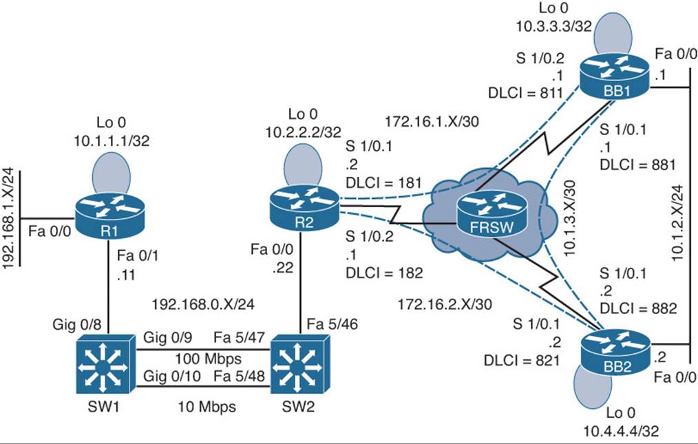
Figure 21-2 Trouble Ticket 2 Topology
As you investigate this issue, you examine baseline data collected after Hot Standby Router Protocol (HSRP) was initially configured. Examples 21-10 and 21-11 provide show and debug commands output collected when HSRP was working properly. Notice that router BB1 was acting as the active HSRP router, whereas router BB2 was acting as the standby HSRP router.
Example 21-10 Baseline Output for Router BB1
BB1#show standby brief
P indicates configured to preempt.
|
Interface Grp Prio P State Active Standby Virtual IP
Fa0/0 1 150 Active local 10.1.2.2 10.1.2.3
BB1#debug standby
HSRP debugging is on
*Mar 1 01:14:21.487: HSRP: Fa0/0 Grp 1 Hello in 10.1.2.2 Standby pri 100 vIP
10.1.2.3
*Mar 1 01:14:23.371: HSRP: Fa0/0 Grp 1 Hello out 10.1.2.1 Active pri 150 vIP
10.1.2.3
BB1#u all
All possible debugging has been turned off
BB1#show standby fa 0/0 1
FastEthernet0/0 - Group 1
State is Active
10 state changes, last state change 00:12:40
Virtual IP address is 10.1.2.3
Active virtual MAC address is 0000.0c07.ac01
Local virtual MAC address is 0000.0c07.ac01 (v1 default)
Hello time 3 sec, hold time 10 sec
Next hello sent in 1.536 secs
Preemption disabled
Active router is local
Standby router is 10.1.2.2, priority 100 (expires in 9.684 sec)
Priority 150 (configured 150)
IP redundancy name is "hsrp-Fa0/0-1" (default)
BB1#show run
...OUTPUT OMITTED...
hostname BB1
!
interface Loopback0
ip address 10.3.3.3 255.255.255.255
!
interface FastEthernet0/0
ip address 10.1.2.1 255.255.255.0
standby 1 ip 10.1.2.3
standby 1 priority 150
!
interface FastEthernet0/1
no ip address
!
router ospf 1
network 0.0.0.0 255.255.255.255 area 0
Example 21-11 Baseline Output for Router BB2
BB2#show standby brief
P indicates configured to preempt.
|
Interface Grp Prio P State Active Standby Virtual IP
Fa0/0 1 100 Standby 10.1.2.1 local 10.1.2.3
BB2#show run
...OUTPUT OMITTED...
hostname BB2
!
interface Loopback0
ip address 10.4.4.4 255.255.255.255
!
interface FastEthernet0/0
ip address 10.1.2.2 255.255.255.0
standby 1 ip 10.1.2.3
!
interface FastEthernet0/1
no ip address
!
router ospf 1
network 0.0.0.0 255.255.255.255 area 0
As part of testing the initial configuration, a ping was sent to the virtual IP address of 10.1.2.3 from router R2 to confirm that HSRP was servicing requests for that IP address. Example 21-12 shows the output from the ping command.
Example 21-12 Pinging the Virtual IP Address from Router R2
R2#ping 10.1.2.3
Type escape sequence to abort.
Sending 5, 100-byte ICMP Echos to 10.1.2.3, timeout is 2 seconds:
!!!!!
As you begin to gather information about the reported problem, you reissue the show standby brief command on routers BB1 and BB2. As shown in Examples 21-13 and 21-14, router BB1 is administratively up with an HSRP priority of 150, whereas router BB2 is administratively up with a priority of 100.
Example 21-13 Examining the HSRP State of Router BB1’s Fast Ethernet 0/0 Interface
BB1#show standby brief
P indicates configured to preempt.
Interface Grp Prio P State Active Standby Virtual IP
Fa0/0 1 150 Standby 10.1.2.2 local 10.1.2.3
Example 21-14 Examining the HSRP State of Router BB2’s Fast Ethernet 0/0 Interface
BB2#show standby brief
P indicates configured to preempt.
Interface Grp Prio P State Active Standby Virtual IP
Fa0/0 1 100 Active local 10.1.2.1 10.1.2.3
Take a moment to look through the baseline information, the topology, and the show command output. Then, hypothesize the underlying cause, explaining why router BB2 is currently the active HSRP router, even though router BB1 has a higher priority. Finally, on a separate sheet of paper, write out a proposed action plan for resolving the reported issue.
Suggested Solution
Upon examination of BB1’s output, it becomes clear that the preempt feature is not enabled for the Fast Ethernet 0/0 interface on BB1. The absence of the preempt feature explains the reported symptom. Specifically, if BB1 had at one point been the active HSRP router for HSRP group 1, and either router BB1 or its Fast Ethernet 0/0 interface became unavailable, BB2 would have become the active router. Then, if BB1 or its Fast Ethernet 0/0 interface once again became available, BB1 would assume a standby HSRP role, because BB1’s Fast Ethernet 0/0 interface was not configured for the preempt feature.
To resolve this configuration issue, the preempt feature is added to BB1’s Fast Ethernet 0/0 interface, as shown in Example 21-15. After enabling the preempt feature, notice that router BB1 regains its active HSRP role.
Example 21-15 Enabling the Preempt Feature on Router BB1’s Fast Ethernet 0/0 Interface
BB1#conf term
Enter configuration commands, one per line. End with CNTL/Z.
BB1(config)#int fa 0/0
BB1(config-if)#standby 1 preempt
BB1(config-if)#end
BB1#
*Mar 1 01:17:39.607: %HSRP-5-STATECHANGE: FastEthernet0/0 Grp 1 state Standby ->
Active
BB1#show standby brief
P indicates configured to preempt.
|
Interface Grp Prio P State Active Standby Virtual IP
Fa0/0 1 150 P Active local 10.1.2.2 10.1.2.3
Trouble Ticket 3
You receive the following trouble ticket:
Enhanced Interior Gateway Routing Protocol (EIGRP) has just been configured as the routing protocol for the network. After configuring EIGRP on all routers and instructing all router interfaces to participate in EIGRP, router R2 does not appear to be load balancing across its subinterfacesto BB1 and BB2 when sending traffic to network 10.1.2.0/24.
This trouble ticket references the topology shown in Figure 21-3.
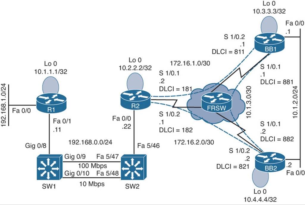
Figure 21-3 Trouble Ticket 3 Topology
As you investigate this issue, you examine baseline data collected after EIGRP was initially configured. Example 21-16 confirms that router R2’s IP routing table contains only a single path to get to the backbone network of 10.1.2.0/24.
Example 21-16 Baseline IP Routing Table on Router R2
R2#show ip route
Codes: C - connected, S - static, R - RIP, M - mobile, B - BGP
D - EIGRP, EX - EIGRP external, O - OSPF, IA - OSPF inter area
N1 - OSPF NSSA external type 1, N2 - OSPF NSSA external type 2
E1 - OSPF external type 1, E2 - OSPF external type 2
i - IS-IS, su - IS-IS summary, L1 - IS-IS level-1, L2 - IS-IS level-2
ia - IS-IS inter area, * - candidate default, U - per-user static route
o - ODR, P - periodic downloaded static route
Gateway of last resort is not set
172.16.0.0/30 is subnetted, 2 subnets
C 172.16.1.0 is directly connected, Serial1/0.1
C 172.16.2.0 is directly connected, Serial1/0.2
10.0.0.0/8 is variably subnetted, 6 subnets, 3 masks
C 10.2.2.2/32 is directly connected, Loopback0
D 10.1.3.0/30 [90/3072000] via 172.16.2.2, 00:00:34, Serial1/0.2
D 10.3.3.3/32 [90/2713600] via 172.16.2.2, 00:00:34, Serial1/0.2
D 10.1.2.0/24 [90/2585600] via 172.16.2.2, 00:00:34, Serial1/0.2
D 10.1.1.1/32 [90/409600] via 192.168.0.11, 00:00:46, FastEthernet0/0
D 10.4.4.4/32 [90/2688000] via 172.16.2.2, 00:00:34, Serial1/0.2
C 192.168.0.0/24 is directly connected, FastEthernet0/0
D 192.168.1.0/24 [90/284160] via 192.168.0.11, 00:18:33, FastEthernet0/0
You then view the EIGRP topology table on router R2 to see whether EIGRP has learned more than one route to reach the 10.1.2.0/24 network. The output, shown in Example 21-17, indicates that the EIGRP topology table knows two routes that could be used to reach the 10.1.2.0/24 network.
Example 21-17 EIGRP Topology Table on Router R2
R2#show ip eigrp topology
IP-EIGRP Topology Table for AS(1)/ID(10.2.2.2)
Codes: P - Passive, A - Active, U - Update, Q - Query, R - Reply,
r - reply Status, s - sia Status
P 10.1.3.0/30, 1 successors, FD is 3072000
via 172.16.2.2 (3072000/2169856), Serial1/0.2
via 172.16.1.1 (4437248/2169856), Serial1/0.1
P 10.2.2.2/32, 1 successors, FD is 128256
via Connected, Loopback0
P 10.1.2.0/24, 1 successors, FD is 2585600
via 172.16.2.2 (2585600/281600), Serial1/0.2
via 172.16.1.1 (3950848/281600), Serial1/0.1
P 10.3.3.3/32, 1 successors, FD is 2713600
via 172.16.2.2 (2713600/409600), Serial1/0.2
via 172.16.1.1 (4053248/128256), Serial1/0.1
P 10.1.1.1/32, 1 successors, FD is 409600
via 192.168.0.11 (409600/128256), FastEthernet0/0
P 10.4.4.4/32, 1 successors, FD is 2688000
via 172.16.2.2 (2688000/128256), Serial1/0.2
via 172.16.1.1 (4078848/409600), Serial1/0.1
P 192.168.0.0/24, 1 successors, FD is 281600
via Connected, FastEthernet0/0
P 192.168.1.0/24, 1 successors, FD is 284160
via 192.168.0.11 (284160/28160), FastEthernet0/0
P 172.16.1.0/30, 1 successors, FD is 3925248
via Connected, Serial1/0.1
P 172.16.2.0/30, 1 successors, FD is 2560000
via Connected, Serial1/0.2
Finally, you examine the EIGRP configuration on router R1, as presented in Example 21-18.
Example 21-18 EIGRP Configuration on Router R2
R2#show run | begin router
router eigrp 1
network 10.2.2.2 0.0.0.0
network 172.16.1.0 0.0.0.3
network 172.16.2.0 0.0.0.3
network 192.168.0.0
auto-summary
Take a moment to look through the show command output and the topology. Then, hypothesize the underlying cause, explaining why router R2’s IP routing table only shows one route to network 10.1.2.0/24, even though the EIGRP topology table knows of two routes to that network. Finally, on a separate sheet of paper, write out a proposed action plan for resolving the reported issue.
Suggested Solution
Upon examination of router R2’s EIGRP topology table (as previously shown in Example 21-17), it becomes clear that the reason router R2 is only injecting one of the 10.1.2.0/24 routes into the IP routing table is that the feasible distances of the two routes are different. By default, EIGRP load balances over routes with equal metrics (that is, equal feasible distances); however, the two routes present in the EIGRP topology table have different metrics.
Examine the two metrics (that is, 2585600 and 3950848), and notice that the metrics differ by less than a factor of 2. Specifically, if you took the smallest metric of 2585600 and multiplied it by 2, the result would be 5171200, which is greater than the largest metric of 3950848.
Because the metrics for the two routes vary by less than a factor of 2, EIGRP’s variance feature could be configured to specify a variance of 2, as shown in Example 21-19. Specifically, this configuration tells EIGRP on router R2 to not only inject the best EIGRP route into the IP routing table, but rather inject the route with the best metric in addition to any route whose metric is within a factor of two of the best metric (that is, in the range 2585600 to 5171200). This allows the route with a metric of 3950848 to also be injected into the IP routing table.
Example 21-19 Enabling the Variance Feature on Router R2
R2#conf term
Enter configuration commands, one per line. End with CNTL/Z.
R2(config)#router eigrp 1
R2(config-router)#variance 2
To confirm that router R2 can now load balance across routers BB1 and BB2 to reach the 10.1.2.0/24 network, examine the output of the show ip route command shown in Example 21-20. This output confirms that router R2 can now load balance over two unequal-cost paths to reach the 10.1.2.0/24 network.
Example 21-20 Examining Router R2’s IP Routing Table After Enabling the Variance Feature
R2#show ip route
Codes: C - connected, S - static, R - RIP, M - mobile, B - BGP
D - EIGRP, EX - EIGRP external, O - OSPF, IA - OSPF inter area
N1 - OSPF NSSA external type 1, N2 - OSPF NSSA external type 2
E1 - OSPF external type 1, E2 - OSPF external type 2
i - IS-IS, su - IS-IS summary, L1 - IS-IS level-1, L2 - IS-IS level-2
ia - IS-IS inter area, * - candidate default, U - per-user static route
o - ODR, P - periodic downloaded static route
Gateway of last resort is not set
172.16.0.0/30 is subnetted, 2 subnets
C 172.16.1.0 is directly connected, Serial1/0.1
C 172.16.2.0 is directly connected, Serial1/0.2
10.0.0.0/8 is variably subnetted, 6 subnets, 3 masks
C 10.2.2.2/32 is directly connected, Loopback0
D 10.1.3.0/30 [90/3072000] via 172.16.2.2, 00:00:03, Serial1/0.2
[90/4437248] via 172.16.1.1, 00:00:03, Serial1/0.1
D 10.3.3.3/32 [90/2713600] via 172.16.2.2, 00:00:03, Serial1/0.2
[90/4053248] via 172.16.1.1, 00:00:03, Serial1/0.1
D 10.1.2.0/24 [90/2585600] via 172.16.2.2, 00:00:03, Serial1/0.2
[90/3950848] via 172.16.1.1, 00:00:03, Serial1/0.1
D 10.1.1.1/32 [90/409600] via 192.168.0.11, 00:00:03, FastEthernet0/0
D 10.4.4.4/32 [90/2688000] via 172.16.2.2, 00:00:03, Serial1/0.2
[90/4078848] via 172.16.1.1, 00:00:03, Serial1/0.1
C 192.168.0.0/24 is directly connected, FastEthernet0/0
D 192.168.1.0/24 [90/284160] via 192.168.0.11, 00:00:04, FastEthernet0/0
Trouble Ticket 4
You receive the following trouble ticket:
For vendor interoperability reasons, a company changed its routing protocol from EIGRP to OSPF. The network was divided into areas, and all interfaces were instructed to participate in OSPF. The configuration was initially working. However, now none of the routers have full reachability to all the subnets.
This trouble ticket references the topology shown in Figure 21-4.
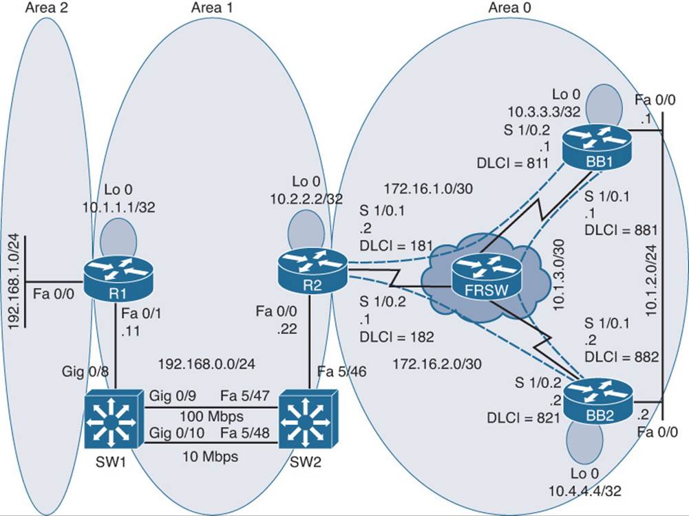
Figure 21-4 Trouble Ticket 4 Topology
As you investigate this issue, you examine baseline data collected after Open Shortest Path First (OSPF) was initially configured. Example 21-21 shows baseline data collected from router R1, when the network was fully operational. Notice that router R1 is configured with a virtual link because it does not physically touch area 0.
Example 21-21 Baseline Configuration Data from Router R1
R1#show run | begin router
router ospf 1
area 1 virtual-link 10.2.2.2
network 10.1.1.1 0.0.0.0 area 1
network 192.168.0.0 0.0.0.255 area 1
network 192.168.1.0 0.0.0.255 area 2
R1#show ip ospf neighbor
Neighbor ID Pri State Dead Time Address Interface
10.2.2.2 0 FULL/- - 192.168.0.22 OSPF_VL2
10.2.2.2 1 FULL/DR 00:00:38 192.168.0.22 FastEthernet0/1
R1#show ip route
Codes: C - connected, S - static, R - RIP, M - mobile, B - BGP
D - EIGRP, EX - EIGRP external, O - OSPF, IA - OSPF inter area
N1 - OSPF NSSA external type 1, N2 - OSPF NSSA external type 2
E1 - OSPF external type 1, E2 - OSPF external type 2
i - IS-IS, su - IS-IS summary, L1 - IS-IS level-1, L2 - IS-IS level-2
ia - IS-IS inter area, * - candidate default, U - per-user static route
o - ODR, P - periodic downloaded static route
Gateway of last resort is not set
172.16.0.0/30 is subnetted, 2 subnets
O 172.16.1.0 [110/134] via 192.168.0.22, 01:34:44, FastEthernet0/1
O 172.16.2.0 [110/81] via 192.168.0.22, 01:34:44, FastEthernet0/1
10.0.0.0/8 is variably subnetted, 6 subnets, 3 masks
O 10.2.2.2/32 [110/2] via 192.168.0.22, 02:24:31, FastEthernet0/1
O 10.1.3.0/30 [110/145] via 192.168.0.22, 01:34:44, FastEthernet0/1
O 10.3.3.3/32 [110/92] via 192.168.0.22, 01:34:44, FastEthernet0/1
O 10.1.2.0/24 [110/91] via 192.168.0.22, 01:34:45, FastEthernet0/1
C 10.1.1.1/32 is directly connected, Loopback0
O 10.4.4.4/32 [110/82] via 192.168.0.22, 01:34:45, FastEthernet0/1
C 192.168.0.0/24 is directly connected, FastEthernet0/1
C 192.168.1.0/24 is directly connected, FastEthernet0/0
R1#show ip ospf
Routing Process "ospf 1" with ID 10.1.1.1
Supports only single TOS(TOS0) routes
Supports opaque LSA
Supports Link-local Signaling (LLS)
Supports area transit capability It is an area border router
Initial SPF schedule delay 5000 msecs
Minimum hold time between two consecutive SPFs 10000 msecs
Maximum wait time between two consecutive SPFs 10000 msecs
Incremental-SPF disabled
Minimum LSA interval 5 secs
Minimum LSA arrival 1000 msecs
LSA group pacing timer 240 secs
Interface flood pacing timer 33 msecs
Retransmission pacing timer 66 msecs
Number of external LSA 0. Checksum Sum 0x000000
Number of opaque AS LSA 0. Checksum Sum 0x000000
Number of DCbitless external and opaque AS LSA 0
Number of DoNotAge external and opaque AS LSA 0
Number of areas in this router is 3. 3 normal 0 stub 0 nssa
Number of areas transit capable is 1
External flood list length 0
Area BACKBONE(0)
Number of interfaces in this area is 1
Area has no authentication
SPF algorithm last executed 01:35:17.308 ago
SPF algorithm executed 9 times
Area ranges are
Number of LSA 12. Checksum Sum 0x063B08
Number of opaque link LSA 0. Checksum Sum 0x000000
Number of DCbitless LSA 0
Number of indication LSA 0
Number of DoNotAge LSA 7
Flood list length 0
Area 1
Number of interfaces in this area is 2 (1 loopback)
This area has transit capability: Virtual Link Endpoint
Area has no authentication
SPF algorithm last executed 02:25:04.377 ago
SPF algorithm executed 22 times
Area ranges are
Number of LSA 10. Checksum Sum 0x059726
Number of opaque link LSA 0. Checksum Sum 0x000000
Number of DCbitless LSA 0
Number of indication LSA 0
Number of DoNotAge LSA 0
Flood list length 0
Area 2
Number of interfaces in this area is 1
Number of indication LSA 0
Number of DoNotAge LSA 0
Flood list length 0
Area has no authentication
SPF algorithm last executed 02:25:15.880 ago
SPF algorithm executed 9 times
Area ranges are
Number of LSA 10. Checksum Sum 0x05F97B
Number of opaque link LSA 0. Checksum Sum 0x000000
Number of DCbitless LSA 0
R1#show ip ospf interface fa0/1
FastEthernet0/1 is up, line protocol is up
Internet Address 192.168.0.11/24, Area 1
Process ID 1, Router ID 10.1.1.1, Network Type BROADCAST, Cost: 1
Transmit Delay is 1 sec, State BDR, Priority 1
Designated Router (ID) 10.2.2.2, Interface address 192.168.0.22
Backup Designated router (ID) 10.1.1.1, Interface address 192.168.0.11
Timer intervals configured, Hello 10, Dead 40, Wait 40, Retransmit 5
oob-resync timeout 40
Hello due in 00:00:00
Supports Link-local Signaling (LLS)
Index 2/2, flood queue length 0
Next 0x0(0)/0x0(0)
Last flood scan length is 1, maximum is 1
Last flood scan time is 0 msec, maximum is 4 msec
Neighbor Count is 1, Adjacent neighbor count is 1
Adjacent with neighbor 10.2.2.2 (Designated Router)
Suppress hello for 0 neighbor(s)
Example 21-22 shows baseline configuration data collected from router R2.
Example 21-22 Baseline Configuration Data from Router R2
R2#show run | begin router
router ospf 1
area 1 virtual-link 10.1.1.1
network 10.2.2.2 0.0.0.0 area 1
network 172.16.1.0 0.0.0.3 area 0
network 172.16.2.0 0.0.0.3 area 0
network 192.168.0.0 0.0.0.255 area 1
R2#show ip ospf neighbor
Neighbor ID Pri State Dead Time Address Interface
10.4.4.4 0 FULL/- 00:00:34 172.16.2.2 Serial1/0.2
10.3.3.3 0 FULL/- 00:00:37 172.16.1.1 Serial1/0.1
10.1.1.1 0 FULL/- - 192.168.0.11 OSPF_VL0
10.1.1.1 1 FULL/BDR 00:00:39 192.168.0.11 FastEthernet0/0
R2#show ip route
Codes: C - connected, S - static, R - RIP, M - mobile, B - BGP
D - EIGRP, EX - EIGRP external, O - OSPF, IA - OSPF inter area
N1 - OSPF NSSA external type 1, N2 - OSPF NSSA external type 2
E1 - OSPF external type 1, E2 - OSPF external type 2
i - IS-IS, su - IS-IS summary, L1 - IS-IS level-1, L2 - IS-IS level-2
ia - IS-IS inter area, * - candidate default, U - per-user static route
o - ODR, P - periodic downloaded static route
Gateway of last resort is not set
172.16.0.0/30 is subnetted, 2 subnets
C 172.16.1.0 is directly connected, Serial1/0.1
C 172.16.2.0 is directly connected, Serial1/0.2
10.0.0.0/8 is variably subnetted, 6 subnets, 3 masks
C 10.2.2.2/32 is directly connected, Loopback0
O 10.1.3.0/30 [110/144] via 172.16.2.2, 01:34:50, Serial1/0.2
O 10.3.3.3/32 [110/91] via 172.16.2.2, 01:34:50, Serial1/0.2
O 10.1.2.0/24 [110/90] via 172.16.2.2, 01:34:50, Serial1/0.2
O 10.1.1.1/32 [110/11] via 192.168.0.11, 02:24:36, FastEthernet0/0
O 10.4.4.4/32 [110/81] via 172.16.2.2, 01:34:50, Serial1/0.2
C 192.168.0.0/24 is directly connected, FastEthernet0/0
O IA 192.168.1.0/24 [110/11] via 192.168.0.11, 01:34:50, FastEthernet0/0
Example 21-23 shows baseline configuration data collected from router BB1.
Example 21-23 Baseline Configuration Data from Router BB1
BB1#show run | begin router
router ospf 1
network 0.0.0.0 255.255.255.255 area 0
BB1#show ip ospf neighbor
Neighbor ID Pri State Dead Time Address Interface
10.4.4.4 1 FULL/DR 00:00:38 10.1.2.2 FastEthernet0/0
10.2.2.2 0 FULL/- 00:00:39 172.16.1.2 Serial1/0.2
10.4.4.4 0 FULL/- 00:00:38 10.1.3.2 Serial1/0.1
BB1#show ip route
Codes: C - connected, S - static, R - RIP, M - mobile, B - BGP
D - EIGRP, EX - EIGRP external, O - OSPF, IA - OSPF inter area
N1 - OSPF NSSA external type 1, N2 - OSPF NSSA external type 2
E1 - OSPF external type 1, E2 - OSPF external type 2
i - IS-IS, su - IS-IS summary, L1 - IS-IS level-1, L2 - IS-IS level-2
ia - IS-IS inter area, * - candidate default, U - per-user static route
o - ODR, P - periodic downloaded static route
Gateway of last resort is not set
172.16.0.0/30 is subnetted, 2 subnets
C 172.16.1.0 is directly connected, Serial1/0.2
O 172.16.2.0 [110/90] via 10.1.2.2, 01:35:01, FastEthernet0/0
10.0.0.0/8 is variably subnetted, 6 subnets, 3 masks
O IA 10.2.2.2/32 [110/91] via 10.1.2.2, 01:35:01, FastEthernet0/0
C 10.1.3.0/30 is directly connected, Serial1/0.1
C 10.3.3.3/32 is directly connected, Loopback0
C 10.1.2.0/24 is directly connected, FastEthernet0/0
O IA 10.1.1.1/32 [110/101] via 10.1.2.2, 01:35:01, FastEthernet0/0
O 10.4.4.4/32 [110/11] via 10.1.2.2, 01:35:01, FastEthernet0/0
O IA 192.168.0.0/24 [110/100] via 10.1.2.2, 01:35:01, FastEthernet0/0
O IA 192.168.1.0/24 [110/101] via 10.1.2.2, 01:35:01, FastEthernet0/0
Example 21-24 shows baseline configuration data collected from router BB2.
Example 21-24 Baseline Configuration Data from Router BB2
BB2#show run | begin router
router ospf 1
network 0.0.0.0 255.255.255.255 area 0
BB2#show ip ospf neighbor
Neighbor ID Pri State Dead Time Address Interface
10.2.2.2 0 FULL/ - 00:00:32 172.16.2.1 Serial1/0.2
10.3.3.3 0 FULL/ - 00:00:39 10.1.3.1 Serial1/0.1
10.3.3.3 1 FULL/BDR 00:00:35 10.1.2.1 FastEthernet0/0
BB2#show ip route
Codes: C - connected, S - static, R - RIP, M - mobile, B - BGP
D - EIGRP, EX - EIGRP external, O - OSPF, IA - OSPF inter area
N1 - OSPF NSSA external type 1, N2 - OSPF NSSA external type 2
E1 - OSPF external type 1, E2 - OSPF external type 2
i - IS-IS, su - IS-IS summary, L1 - IS-IS level-1, L2 - IS-IS level-2
ia - IS-IS inter area, * - candidate default, U - per-user static route
o - ODR, P - periodic downloaded static route
Gateway of last resort is not set
172.16.0.0/30 is subnetted, 2 subnets
O IA 192.168.1.0/24 [110/101] via 10.1.2.2, 01:35:01, FastEthernet0/0
O 172.16.1.0 [110/143] via 10.1.2.1, 01:35:06, FastEthernet0/0
C 172.16.2.0 is directly connected, Serial1/0.2
10.0.0.0/8 is variably subnetted, 6 subnets, 3 masks
O IA 10.2.2.2/32 [110/81] via 172.16.2.1, 01:35:06, Serial1/0.2
C 10.1.3.0/30 is directly connected, Serial1/0.1
O 10.3.3.3/32 [110/11] via 10.1.2.1, 01:35:06, FastEthernet0/0
C 10.1.2.0/24 is directly connected, FastEthernet0/0
O IA 10.1.1.1/32 [110/91] via 172.16.2.1, 01:35:06, Serial1/0.2
C 10.4.4.4/32 is directly connected, Loopback0
O IA 192.168.0.0/24 [110/90] via 172.16.2.1, 01:35:06, Serial1/0.2
O IA 192.168.1.0/24 [110/91] via 172.16.2.1, 01:35:06, Serial1/0.2
Now that you have seen the baseline data, the following examples present you with data collected after the trouble ticket was issued. Example 21-25 shows information collected from router R1. Notice that router R1’s routing table can no longer see the Loopback 0 IP address of router BB2 (that is, 10.4.4.4/32). Also, notice that the virtual link between area 2 and area 0 is down.
Example 21-25 Information Gathered from Router R1 After the Trouble Ticket Was Issued
R1#show ip route
Codes: C - connected, S - static, R - RIP, M - mobile, B - BGP
D - EIGRP, EX - EIGRP external, O - OSPF, IA - OSPF inter area
N1 - OSPF NSSA external type 1, N2 - OSPF NSSA external type 2
E1 - OSPF external type 1, E2 - OSPF external type 2
i - IS-IS, su - IS-IS summary, L1 - IS-IS level-1, L2 - IS-IS level-2
ia - IS-IS inter area, * - candidate default, U - per-user static route
o - ODR, P - periodic downloaded static route
Gateway of last resort is not set
172.16.0.0/30 is subnetted, 2 subnets
O IA 172.16.1.0 [110/134] via 192.168.0.22, 00:00:31, FastEthernet0/1
O IA 172.16.2.0 [110/81] via 192.168.0.22, 00:00:31, FastEthernet0/1
10.0.0.0/8 is variably subnetted, 5 subnets, 3 masks
O 10.2.2.2/32 [110/2] via 192.168.0.22, 00:00:51, FastEthernet0/1
O IA 10.1.3.0/30 [110/198] via 192.168.0.22, 00:00:31, FastEthernet0/1
O IA 10.3.3.3/32 [110/135] via 192.168.0.22, 00:00:31, FastEthernet0/1
O IA 10.1.2.0/24 [110/144] via 192.168.0.22, 00:00:32, FastEthernet0/1
C 10.1.1.1/32 is directly connected, Loopback0
C 192.168.0.0/24 is directly connected, FastEthernet0/1
C 192.168.1.0/24 is directly connected, FastEthernet0/0
R1#show run | begin router
router ospf 1
log-adjacency-changes
area 2 virtual-link 10.2.2.2
network 10.1.1.1 0.0.0.0 area 1
network 192.168.0.0 0.0.0.255 area 1
network 192.168.1.0 0.0.0.255 area 2
R1#show ip ospf virtual-links
Virtual Link OSPF_VL4 to router 10.2.2.2 is down
Run as demand circuit
DoNotAge LSA allowed.
Transit area 2, Cost of using 65535
Transmit Delay is 1 sec, State DOWN,
Timer intervals configured, Hello 10, Dead 40, Wait 40, Retransmit 5
Example 21-26 shows the IP routing table on router R2 after the trouble ticket was issued. Notice that the routing table of router R2 can no longer see the Loopback 0 IP address of router BB2 (that is, 10.4.4.4/32). Also, notice that network 192.168.1.0/24, connected to router R1’s Fast Ethernet 0/0 interface, is not present in router R2’s IP routing table.
Example 21-26 Router R2’s IP Routing Table After the Trouble Ticket Was Issued
R2#show ip route
Codes: C - connected, S - static, R - RIP, M - mobile, B - BGP
D - EIGRP, EX - EIGRP external, O - OSPF, IA - OSPF inter area
N1 - OSPF NSSA external type 1, N2 - OSPF NSSA external type 2
E1 - OSPF external type 1, E2 - OSPF external type 2
i - IS-IS, su - IS-IS summary, L1 - IS-IS level-1, L2 - IS-IS level-2
ia - IS-IS inter area, * - candidate default, U - per-user static route
o - ODR, P - periodic downloaded static route
Gateway of last resort is not set
172.16.0.0/30 is subnetted, 2 subnets
C 172.16.1.0 is directly connected, Serial1/0.1
C 172.16.2.0 is directly connected, Serial1/0.2
10.0.0.0/8 is variably subnetted, 5 subnets, 3 masks
C 10.2.2.2/32 is directly connected, Loopback0
O 10.1.3.0/30 [110/197] via 172.16.1.1, 00:00:53, Serial1/0.1
O 10.3.3.3/32 [110/134] via 172.16.1.1, 00:00:53, Serial1/0.1
O 10.1.2.0/24 [110/143] via 172.16.1.1, 00:00:53, Serial1/0.1
O 10.1.1.1/32 [110/11] via 192.168.0.11, 00:00:53, FastEthernet0/0
C 192.168.0.0/24 is directly connected, FastEthernet0/0
Before moving forward to investigate the remainder of the network, do you already see an issue that needs to be resolved? The fact that router R2 cannot see network 192.168.1.0/24 off of router R1 is independent of any configuration on routers BB1 or BB2. So, take a few moments to review the information collected thus far, and hypothesize the issue that is preventing router R2 from seeing network 192.168.1.0/24. On a separate sheet of paper, write your solution to the issue you identified.
Issue 1: Suggested Solution
The virtual link configuration on router R1 was incorrect. Specifically, the transit area in the area number virtual-link router_id command was configured as area 2. However, the transit area should have been area 1. Example 21-27 shows the commands used to correct this misconfiguration.
Example 21-27 Correcting the Virtual Link Configuration of R1
R1#conf term
Enter configuration commands, one per line. End with CNTL/Z.
R1(config)#router ospf 1
R1(config-router)#no area 2 virtual-link 10.2.2.2
R1(config-router)#area 1 virtual-link 10.2.2.2
After you correct the virtual link configuration on router R1, network 192.168.1.0/24 is present in router R2’s IP routing table, as illustrated in Example 21-28. Notice, however, that the Loopback 0 IP address of router BB2 (that is, 10.4.4.4/32) is still not visible in router R2’s IP routing table.
Example 21-28 Router R2’s IP Routing Table After Correcting the Virtual Link Configuration
R2#show ip route
Codes: C - connected, S - static, R - RIP, M - mobile, B - BGP
D - EIGRP, EX - EIGRP external, O - OSPF, IA - OSPF inter area
N1 - OSPF NSSA external type 1, N2 - OSPF NSSA external type 2
E1 - OSPF external type 1, E2 - OSPF external type 2
i - IS-IS, su - IS-IS summary, L1 - IS-IS level-1, L2 - IS-IS level-2
ia - IS-IS inter area, * - candidate default, U - per-user static route
o - ODR, P - periodic downloaded static route
Gateway of last resort is not set
172.16.0.0/30 is subnetted, 2 subnets
C 172.16.1.0 is directly connected, Serial1/0.1
C 172.16.2.0 is directly connected, Serial1/0.2
10.0.0.0/8 is variably subnetted, 5 subnets, 3 masks
C 10.2.2.2/32 is directly connected, Loopback0
O 10.1.3.0/30 [110/197] via 172.16.1.1, 00:00:18, Serial1/0.1
O 10.3.3.3/32 [110/134] via 172.16.1.1, 00:00:18, Serial1/0.1
O 10.1.2.0/24 [110/143] via 172.16.1.1, 00:00:18, Serial1/0.1
O 10.1.1.1/32 [110/11] via 192.168.0.11, 00:00:18, FastEthernet0/0
C 192.168.0.0/24 is directly connected, FastEthernet0/0
O IA 192.168.1.0/24 [110/11] via 192.168.0.11, 00:00:18, FastEthernet0/0
With one issue now resolved, continue to collect information on router R2. Example 21-29 indicates that router R2 has not formed an adjacency with router BB2, which has an OSPF router ID of 10.4.4.4.
Example 21-29 OSPF Neighbors of Router R2
R2#show ip ospf neighbor
Neighbor ID Pri State Dead Time Address Interface
10.3.3.3 0 FULL/- 00:00:37 172.16.1.1 Serial1/0.1
10.1.1.1 0 FULL/- - 192.168.0.11 OSPF_VL1
10.1.1.1 1 FULL/DR 00:00:39 192.168.0.11 FastEthernet0/0
R2#show run | begin router
router ospf 2
log-adjacency-changes
area 1 virtual-link 10.1.1.1
network 10.2.2.2 0.0.0.0 area 1
network 172.16.1.0 0.0.0.3 area 0
network 172.16.2.0 0.0.0.3 area 0
network 192.168.0.0 0.0.0.255 area 1
Even though router R2 has not formed an adjacency with router BB2, Example 21-30 shows the output of a ping command, verifying that router R2 can reach router BB2.
Example 21-30 Pinging Router BB2 from Router R2
R2#ping 172.16.2.2
Type escape sequence to abort.
Sending 5, 100-byte ICMP Echos to 172.16.2.2, timeout is 2 seconds:
!!!!!
Success rate is 100 percent (5/5), round-trip min/avg/max = 52/92/144 ms
The topology diagram indicates that router R2 connects with router BB2 via subinterface Serial 1/0.2. Therefore, the show interface s1/0.2 command is issued on router R2. The output provided in Example 21-31 states that the subinterface is up and functional.
Example 21-31 Serial 1/0.2 Subinterface of Router R2
R2#show interface s1/0.2
Serial1/0.2 is up, line protocol is up
Hardware is M4T
Internet address is 172.16.2.1/30
MTU 1500 bytes, BW 1250 Kbit, DLY 20000 usec,
reliability 255/255, txload 1/255, rxload 1/255
Encapsulation FRAME-RELAY
Last clearing of "show interface" counters never
Example 21-32 confirms that router BB2 is adjacent at Layer 2 with router R2.
Example 21-32 CDP Neighbors of Router R2
R2#show cdp neighbor
Capability Codes: R - Router, T - Trans Bridge, B - Source Route Bridge
S - Switch, H - Host, I - IGMP, r - Repeater
Device ID Local Intrfce Holdtime Capability Platform Port ID
BB1 Ser 1/0.1 152 R S I 2691 Ser 1/0.2
BB2 Ser 1/0.2 143 R S I 2691 Ser 1/0.2
R1 Fas 0/0 144 R S I 2611XM Fas 0/1
The output of Example 21-33 shows the OSPF status of router R2’s Serial 1/0.2 subinterface.
Example 21-33 OSPF Status of Router R2 on Subinterface Serial 1/0.2
R2#show ip ospf interface s1/0.2
Serial1/0.2 is up, line protocol is up
Internet Address 172.16.2.1/30, Area 0
Process ID 1, Router ID 10.2.2.2, Network Type POINT_TO_POINT, Cost: 64
Transmit Delay is 1 sec, State POINT_TO_POINT,
Timer intervals configured, Hello 10, Dead 40, Wait 40, Retransmit 5
oob-resync timeout 40
Hello due in 00:00:09
Supports Link-local Signaling (LLS)
Index 3/4, flood queue length 0
Next 0x0(0)/0x0(0)
Last flood scan length is 1, maximum is 4
Last flood scan time is 0 msec, maximum is 4 msec
Neighbor Count is 0, Adjacent neighbor count is 0
Suppress hello for 0 neighbor(s)
Now that data has been collected for router R2, the troubleshooting focus moves to router BB1 in Example 21-34. Notice that BB1 also lacks a route to router BB2’s Loopback 0 IP address of 10.4.4.4/32. Also, even though router BB1 has two direct connections to router BB2, router BB1 has not formed an OSPF adjacency with router BB2. Notice that router BB2 is router BB1’s Cisco Discovery Protocol (CDP) neighbor, both on interface Fast Ethernet 0/0 and on subinterface Serial 1/0.1.
Example 21-34 Data Collected from Router BB1 After the Trouble Ticket
BB1#show ip route
Codes: C - connected, S - static, R - RIP, M - mobile, B - BGP
D - EIGRP, EX - EIGRP external, O - OSPF, IA - OSPF inter area
N1 - OSPF NSSA external type 1, N2 - OSPF NSSA external type 2
E1 - OSPF external type 1, E2 - OSPF external type 2
i - IS-IS, su - IS-IS summary, L1 - IS-IS level-1, L2 - IS-IS level-2
ia - IS-IS inter area, * - candidate default, U - per-user static route
o - ODR, P - periodic downloaded static route
Gateway of last resort is not set
172.16.0.0/30 is subnetted, 2 subnets
C 172.16.1.0 is directly connected, Serial1/0.2
O 172.16.2.0 [110/213] via 172.16.1.2, 00:01:02, Serial1/0.2
10.0.0.0/8 is variably subnetted, 5 subnets, 3 masks
O IA 10.2.2.2/32 [110/134] via 172.16.1.2, 00:01:02, Serial1/0.2
C 10.1.3.0/30 is directly connected, Serial1/0.1
C 10.3.3.3/32 is directly connected, Loopback0
C 10.1.2.0/24 is directly connected, FastEthernet0/0
O IA 10.1.1.1/32 [110/144] via 172.16.1.2, 00:01:02, Serial1/0.2
O IA 192.168.0.0/24 [110/143] via 172.16.1.2, 00:01:02, Serial1/0.2
BB1#show ip ospf neighbor
Neighbor ID Pri State Dead Time Address Interface
10.2.2.2 0 FULL/- 00:00:30 172.16.1.2 Serial1/0.2
BB1#show run | begin router
router ospf 1
log-adjacency-changes
network 0.0.0.0 255.255.255.255 area 0
BB1#show cdp neigh
Capability Codes: R - Router, T - Trans Bridge, B - Source Route Bridge
S - Switch, H - Host, I - IGMP, r - Repeater
Device ID Local Intrfce Holdtime Capability Platform Port ID
BB2 Ser 1/0.1 148 R S I 2691 Ser 1/0.1
BB2 Fas 0/0 148 R S I 2691 Fas 0/0
R2 Ser 1/0.2 130 R S I 2691 Ser 1/0.1
BB1#show run
...OUTPUT OMITTED...
interface FastEthernet0/0
ip address 10.1.2.1 255.255.255.0
ip ospf network non-broadcast
duplex auto
speed auto
!
interface Serial1/0
no ip address
encapsulation frame-relay
!
interface Serial1/0.1 point-to-point
ip address 10.1.3.1 255.255.255.252
ip ospf hello-interval 60
ip ospf dead-interval 200
frame-relay interface-dlci 881
!
interface Serial1/0.2 point-to-point
bandwidth 750
ip address 172.16.1.1 255.255.255.252
frame-relay interface-dlci 811
...OUTPUT OMITTED...
The data collection continues on router BB2. Example 21-35 provides output from several show commands. Notice that router BB2 has not learned networks via OSPF.
Example 21-35 Data Collected from Router BB2 After the Trouble Ticket
BB2#show ip route
Codes: C - connected, S - static, R - RIP, M - mobile, B - BGP
D - EIGRP, EX - EIGRP external, O - OSPF, IA - OSPF inter area
N1 - OSPF NSSA external type 1, N2 - OSPF NSSA external type 2
E1 - OSPF external type 1, E2 - OSPF external type 2
i - IS-IS, su - IS-IS summary, L1 - IS-IS level-1, L2 - IS-IS level-2
ia - IS-IS inter area, * - candidate default, U - per-user static route
o - ODR, P - periodic downloaded static route
Gateway of last resort is not set
172.16.0.0/30 is subnetted, 1 subnets
C 172.16.2.0 is directly connected, Serial1/0.2
10.0.0.0/8 is variably subnetted, 3 subnets, 3 masks
C 10.1.3.0/30 is directly connected, Serial1/0.1
C 10.1.2.0/24 is directly connected, FastEthernet0/0
C 10.4.4.4/32 is directly connected, Loopback0
BB2#show run | begin router
router ospf 1
log-adjacency-changes
network 0.0.0.0 255.255.255.255 area 0
BB2#show ip ospf interface s1/0.1
Serial1/0.1 is up, line protocol is up
Internet Address 10.1.3.2/30, Area 0
Process ID 1, Router ID 10.4.4.4, Network Type POINT_TO_POINT, Cost: 64
Transmit Delay is 1 sec, State POINT_TO_POINT,
Timer intervals configured, Hello 10, Dead 40, Wait 40, Retransmit 5
oob-resync timeout 40
Hello due in 00:00:09
Supports Link-local Signaling (LLS)
Index 2/2, flood queue length 0
Next 0x0(0)/0x0(0)
Last flood scan length is 1, maximum is 3
Last flood scan time is 0 msec, maximum is 4 msec
Neighbor Count is 0, Adjacent neighbor count is 0
Suppress hello for 0 neighbor(s)
BB2#show ip ospf interface s1/0.2
Serial1/0.2 is up, line protocol is up
Internet Address 172.16.2.2/30, Area 0
Process ID 1, Router ID 10.4.4.4, Network Type NON_BROADCAST, Cost: 80
Transmit Delay is 1 sec, State DR, Priority 1
Designated Router (ID) 10.4.4.4, Interface address 172.16.2.2
No backup designated router on this network
Timer intervals configured, Hello 30, Dead 120, Wait 120, Retransmit 5
oob-resync timeout 120
Hello due in 00:00:09
Supports Link-local Signaling (LLS)
Index 3/3, flood queue length 0
Next 0x0(0)/0x0(0)
Last flood scan length is 1, maximum is 1
Last flood scan time is 0 msec, maximum is 4 msec
Neighbor Count is 0, Adjacent neighbor count is 0
Suppress hello for 0 neighbor(s)
!
BB2#show run | begin interface
interface FastEthernet0/0
ip address 10.1.2.2 255.255.255.0
!
interface Serial1/0
no ip address
encapsulation frame-relay
!
interface Serial1/0.1 point-to-point
ip address 10.1.3.2 255.255.255.252
frame-relay interface-dlci 882
!
interface Serial1/0.2 point-to-point
bandwidth 1250
ip address 172.16.2.2 255.255.255.252
ip ospf network non-broadcast
frame-relay interface-dlci 821
!
...OUTPUT OMITTED...
Based on the preceding show command output from routers R2, BB1, and BB2, hypothesize what you consider to be the issue or issues still impacting the network. Then, on a separate sheet of paper, write how you would solve the identified issue or issues.
Issue 2: Suggested Solution
Subinterface Serial 1/0.1 on router BB1 had non-default hello and dead timers, which did not match the timers at the far end of the Frame Relay link. Example 21-36 illustrates how these nondefault values were reset.
Example 21-36 Correcting the Nondefault Timer Configuration of Router BB1
BB1#conf term
Enter configuration commands, one per line. End with CNTL/Z.
BB1(config)#int s1/0.1
BB1(config-subif)#no ip ospf hello-interval 60
BB1(config-subif)#no ip ospf dead-interval 200
Issue 3: Suggested Solution
Interface Fast Ethernet 0/0 on router BB1 was configured with an incorrect OSPF network type of nonbroadcast. Example 21-37 demonstrates how this OSPF interface was reset to its default OSPF network type (that is, the broadcast OSPF network type).
Example 21-37 Correcting the Incorrect OSPF Network Type Configuration of Router BB1
BB1#conf term
Enter configuration commands, one per line. End with CNTL/Z.
BB1(config)#int fa 0/0
BB1(config-if)#no ip ospf network non-broadcast
Issue 4: Suggested Solution
Similar to the incorrect OSPF network type on router BB1’s Fast Ethernet 0/0 interface, the Serial 1/0.2 subinterface on router BB2 was configured incorrectly. A point-to-point Frame Relay subinterface defaults to an OSPF network type of point-to-point; however, Serial 1/0.2 had been configured as an OSPF network type of nonbroadcast. Example 21-38 reviews how this nondefault OSPF network type configuration was removed.
Example 21-38 Correcting Router BB2’s Incorrect OSPF Network Type Configuration
BB2#conf term
Enter configuration commands, one per line. End with CNTL/Z.
BB2(config)#int s1/0.2
BB2(config-subif)#no ip ospf network non-broadcast
After all the previous misconfigurations are corrected, all routers in the topology once again have full reachability throughout the network. Examples 21-39, 21-40, 21-41, and 21-42 show output from the show ip route and show ip ospf neighbor commands issued on all routers, confirming the full reachability of each router.
Example 21-39 Confirming the Full Reachability of Router R1
R1#show ip route
Codes: C - connected, S - static, R - RIP, M - mobile, B - BGP
D - EIGRP, EX - EIGRP external, O - OSPF, IA - OSPF inter area
N1 - OSPF NSSA external type 1, N2 - OSPF NSSA external type 2
E1 - OSPF external type 1, E2 - OSPF external type 2
i - IS-IS, su - IS-IS summary, L1 - IS-IS level-1, L2 - IS-IS level-2
ia - IS-IS inter area, * - candidate default, U - per-user static route
o - ODR, P - periodic downloaded static route
Gateway of last resort is not set
172.16.0.0/30 is subnetted, 2 subnets
O 172.16.1.0 [110/134] via 192.168.0.22, 00:00:03, FastEthernet0/1
O 172.16.2.0 [110/81] via 192.168.0.22, 00:00:03, FastEthernet0/1
10.0.0.0/8 is variably subnetted, 6 subnets, 3 masks
O 10.2.2.2/32 [110/2] via 192.168.0.22, 00:08:18, FastEthernet0/1
O 10.1.3.0/30 [110/145] via 192.168.0.22, 00:00:03, FastEthernet0/1
O 10.3.3.3/32 [110/92] via 192.168.0.22, 00:00:03, FastEthernet0/1
O 10.1.2.0/24 [110/91] via 192.168.0.22, 00:00:04, FastEthernet0/1
C 10.1.1.1/32 is directly connected, Loopback0
O 10.4.4.4/32 [110/82] via 192.168.0.22, 00:00:04, FastEthernet0/1
C 192.168.0.0/24 is directly connected, FastEthernet0/1
C 192.168.1.0/24 is directly connected, FastEthernet0/0
R1#show ip ospf neighbor
Neighbor ID Pri State Dead Time Address Interface
10.2.2.2 0 FULL/- - 192.168.0.22 OSPF_VL5
10.2.2.2 1 FULL/BDR 00:00:34 192.168.0.22 FastEthernet0/1
Example 21-40 Confirming the Full Reachability of Router R2
R2#show ip route
Codes: C - connected, S - static, R - RIP, M - mobile, B - BGP
D - EIGRP, EX - EIGRP external, O - OSPF, IA - OSPF inter area
N1 - OSPF NSSA external type 1, N2 - OSPF NSSA external type 2
E1 - OSPF external type 1, E2 - OSPF external type 2
i - IS-IS, su - IS-IS summary, L1 - IS-IS level-1, L2 - IS-IS level-2
ia - IS-IS inter area, * - candidate default, U - per-user static route
o - ODR, P - periodic downloaded static route
Gateway of last resort is not set
172.16.0.0/30 is subnetted, 2 subnets
C 172.16.1.0 is directly connected, Serial1/0.1
C 172.16.2.0 is directly connected, Serial1/0.2
10.0.0.0/8 is variably subnetted, 6 subnets, 3 masks
C 10.2.2.2/32 is directly connected, Loopback0
O 10.1.3.0/30 [110/144] via 172.16.2.2, 00:00:15, Serial1/0.2
O 10.3.3.3/32 [110/91] via 172.16.2.2, 00:00:15, Serial1/0.2
O 10.1.2.0/24 [110/90] via 172.16.2.2, 00:00:15, Serial1/0.2
O 10.1.1.1/32 [110/11] via 192.168.0.11, 00:08:29, FastEthernet0/0
O 10.4.4.4/32 [110/81] via 172.16.2.2, 00:00:15, Serial1/0.2
C 192.168.0.0/24 is directly connected, FastEthernet0/0
O IA 192.168.1.0/24 [110/11] via 192.168.0.11, 00:00:15, FastEthernet0/0
R2#show ip ospf neighbor
Neighbor ID Pri State Dead Time Address Interface
10.4.4.4 0 FULL/ - 00:00:33 172.16.2.2 Serial1/0.2
10.3.3.3 0 FULL/ - 00:00:38 172.16.1.1 Serial1/0.1
10.1.1.1 0 FULL/ - - 192.168.0.11 OSPF_VL1
10.1.1.1 1 FULL/DR 00:00:30 192.168.0.11 FastEthernet0/0
Example 21-41 Confirming the Full Reachability of Router BB1
BB1#show ip route
Codes: C - connected, S - static, R - RIP, M - mobile, B - BGP
D - EIGRP, EX - EIGRP external, O - OSPF, IA - OSPF inter area
N1 - OSPF NSSA external type 1, N2 - OSPF NSSA external type 2
E1 - OSPF external type 1, E2 - OSPF external type 2
i - IS-IS, su - IS-IS summary, L1 - IS-IS level-1, L2 - IS-IS level-2
ia - IS-IS inter area, * - candidate default, U - per-user static route
o - ODR, P - periodic downloaded static route
Gateway of last resort is not set
172.16.0.0/30 is subnetted, 2 subnets
C 172.16.1.0 is directly connected, Serial1/0.2
O 172.16.2.0 [110/90] via 10.1.2.2, 00:00:29, FastEthernet0/0
10.0.0.0/8 is variably subnetted, 6 subnets, 3 masks
O IA 10.2.2.2/32 [110/91] via 10.1.2.2, 00:00:29, FastEthernet0/0
C 10.1.3.0/30 is directly connected, Serial1/0.1
C 10.3.3.3/32 is directly connected, Loopback0
C 10.1.2.0/24 is directly connected, FastEthernet0/0
O IA 10.1.1.1/32 [110/101] via 10.1.2.2, 00:00:29, FastEthernet0/0
O 10.4.4.4/32 [110/11] via 10.1.2.2, 00:00:29, FastEthernet0/0
O IA 192.168.0.0/24 [110/100] via 10.1.2.2, 00:00:29, FastEthernet0/0
O IA 192.168.1.0/24 [110/101] via 10.1.2.2, 00:00:29, FastEthernet0/0
BB1#show ip ospf neighbor
Neighbor ID Pri State Dead Time Address Interface
10.4.4.4 1 FULL/DR 00:00:34 10.1.2.2 FastEthernet0/
10.2.2.2 0 FULL/ - 00:00:39 172.16.1.2 Serial1/0.2
10.4.4.4 0 FULL/ - 00:00:33 10.1.3.2 Serial1/0.1
Example 21-42 Confirming the Full Reachability of Router BB2
BB2#show ip route
Codes: C - connected, S - static, R - RIP, M - mobile, B - BGP
D - EIGRP, EX - EIGRP external, O - OSPF, IA - OSPF inter area
N1 - OSPF NSSA external type 1, N2 - OSPF NSSA external type 2
E1 - OSPF external type 1, E2 - OSPF external type 2
i - IS-IS, su - IS-IS summary, L1 - IS-IS level-1, L2 - IS-IS level-2
ia - IS-IS inter area, * - candidate default, U - per-user static route
o - ODR, P - periodic downloaded static route
Gateway of last resort is not set
172.16.0.0/30 is subnetted, 2 subnets
O 172.16.1.0 [110/143] via 10.1.2.1, 00:00:42, FastEthernet0/0
C 172.16.2.0 is directly connected, Serial1/0.2
10.0.0.0/8 is variably subnetted, 6 subnets, 3 masks
O IA 10.2.2.2/32 [110/81] via 172.16.2.1, 00:00:42, Serial1/0.2
C 10.1.3.0/30 is directly connected, Serial1/0.1
O 10.3.3.3/32 [110/11] via 10.1.2.1, 00:00:42, FastEthernet0/0
C 10.1.2.0/24 is directly connected, FastEthernet0/0
O IA 10.1.1.1/32 [110/91] via 172.16.2.1, 00:00:42, Serial1/0.2
C 10.4.4.4/32 is directly connected, Loopback0
O IA 192.168.0.0/24 [110/90] via 172.16.2.1, 00:00:42, Serial1/0.2
O IA 192.168.1.0/24 [110/91] via 172.16.2.1, 00:00:42, Serial1/0.2
BB2#show ip ospf neighbor
Neighbor ID Pri State Dead Time Address Interface
10.2.2.2 0 FULL/ - 00:00:38 172.16.2.1 Serial1/0.2
10.3.3.3 0 FULL/ - 00:00:29 10.1.3.1 Serial1/0.1
10.3.3.3 1 FULL/BDR 00:00:34 10.1.2.1 FastEthernet0/0
Trouble Ticket 5
You receive the following trouble ticket:
Company A has acquired company B. Company A’s network (that is, routers R1 and R2) uses EIGRP, whereas Company B’s network (that is, routers BB1 and BB2) uses OSPF. Router R2 was configured as a boundary router, and router R2’s configuration specifies that EIGRP and OSPF are mutually redistributed. The configuration was originally functional. However, routers R1, BB1, and BB2 do not currently see all the subnets present in the network.
This trouble ticket references the topology shown in Figure 21-5.
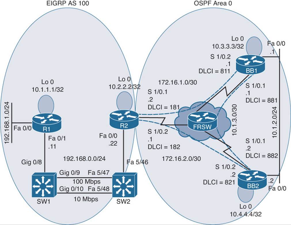
Figure 21-5 Trouble Ticket 5: Topology
You begin your troubleshooting efforts by analyzing baseline information collected when the configuration was working properly. Examples 21-43, 21-44, 21-45, and 21-46 provide output from the show ip route command on each router.
Example 21-43 Baseline Output for Router R1
R1#show ip route
Codes: C - connected, S - static, R - RIP, M - mobile, B - BGP
D - EIGRP, EX - EIGRP external, O - OSPF, IA - OSPF inter area
N1 - OSPF NSSA external type 1, N2 - OSPF NSSA external type 2
E1 - OSPF external type 1, E2 - OSPF external type 2
i - IS-IS, su - IS-IS summary, L1 - IS-IS level-1, L2 - IS-IS level-2
ia - IS-IS inter area, * - candidate default, U - per-user static route
o - ODR, P - periodic downloaded static route
Gateway of last resort is not set
172.16.0.0/30 is subnetted, 2 subnets
D EX 172.16.1.0 [170/1734656] via 192.168.0.22, 00:04:39, FastEthernet0/1
D EX 172.16.2.0 [170/1734656] via 192.168.0.22, 00:04:39, FastEthernet0/1
10.0.0.0/8 is variably subnetted, 6 subnets, 3 masks
D 10.2.2.2/32 [90/156160] via 192.168.0.22, 00:04:39, FastEthernet0/1
D EX 10.1.3.0/30 [170/1734656] via 192.168.0.22, 00:04:39, FastEthernet0/1
D EX 10.3.3.3/32 [170/1734656] via 192.168.0.22, 00:04:39, FastEthernet0/1
D EX 10.1.2.0/24 [170/1734656] via 192.168.0.22, 00:04:40, FastEthernet0/1
C 10.1.1.1/32 is directly connected, Loopback0
D EX 10.4.4.4/32 [170/1734656] via 192.168.0.22, 00:04:40, FastEthernet0/1
C 192.168.0.0/24 is directly connected, FastEthernet0/1
C 192.168.1.0/24 is directly connected, FastEthernet0/0
Example 21-44 Baseline Output for Router R2
R2#show ip route
Codes: C - connected, S - static, R - RIP, M - mobile, B - BGP
D - EIGRP, EX - EIGRP external, O - OSPF, IA - OSPF inter area
N1 - OSPF NSSA external type 1, N2 - OSPF NSSA external type 2
E1 - OSPF external type 1, E2 - OSPF external type 2
i - IS-IS, su - IS-IS summary, L1 - IS-IS level-1, L2 - IS-IS level-2
ia - IS-IS inter area, * - candidate default, U - per-user static route
o - ODR, P - periodic downloaded static route
Gateway of last resort is not set
172.16.0.0/30 is subnetted, 2 subnets
C 172.16.1.0 is directly connected, Serial1/0.1
C 172.16.2.0 is directly connected, Serial1/0.2
10.0.0.0/8 is variably subnetted, 6 subnets, 3 masks
C 10.2.2.2/32 is directly connected, Loopback0
O 10.1.3.0/30 [110/144] via 172.16.2.2, 00:07:12, Serial1/0.2
O 10.3.3.3/32 [110/91] via 172.16.2.2, 00:07:12, Serial1/0.2
O 10.1.2.0/24 [110/90] via 172.16.2.2, 00:07:12, Serial1/0.2
D 10.1.1.1/32 [90/409600] via 192.168.0.11, 00:04:46, FastEthernet0/0
O 10.4.4.4/32 [110/81] via 172.16.2.2, 00:07:12, Serial1/0.2
C 192.168.0.0/24 is directly connected, FastEthernet0/0
D 192.168.1.0/24 [90/284160] via 192.168.0.11, 00:04:46, FastEthernet0/0
Example 21-45 Baseline Output for Router BB1
BB1#show ip route
Codes: C - connected, S - static, R - RIP, M - mobile, B - BGP
D - EIGRP, EX - EIGRP external, O - OSPF, IA - OSPF inter area
N1 - OSPF NSSA external type 1, N2 - OSPF NSSA external type 2
E1 - OSPF external type 1, E2 - OSPF external type 2
i - IS-IS, su - IS-IS summary, L1 - IS-IS level-1, L2 - IS-IS level-2
ia - IS-IS inter area, * - candidate default, U - per-user static route
o - ODR, P - periodic downloaded static route
Gateway of last resort is not set
172.16.0.0/30 is subnetted, 2 subnets
C 172.16.1.0 is directly connected, Serial1/0.2
O 172.16.2.0 [110/90] via 10.1.2.2, 00:07:08, FastEthernet0/0
10.0.0.0/8 is variably subnetted, 6 subnets, 3 masks
O E2 10.2.2.2/32 [110/64] via 10.1.2.2, 00:07:08, FastEthernet0/0
C 10.1.3.0/30 is directly connected, Serial1/0.1
C 10.3.3.3/32 is directly connected, Loopback0
C 10.1.2.0/24 is directly connected, FastEthernet0/0
O E2 10.1.1.1/32 [110/64] via 10.1.2.2, 00:04:49, FastEthernet0/0
O 10.4.4.4/32 [110/11] via 10.1.2.2, 00:07:08, FastEthernet0/0
O E2 192.168.0.0/24 [110/64] via 10.1.2.2, 00:07:08, FastEthernet0/0
O E2 192.168.1.0/24 [110/64] via 10.1.2.2, 00:04:49, FastEthernet0/0
Example 21-46 Baseline Output for Router BB2
BB2#show ip route
Codes: C - connected, S - static, R - RIP, M - mobile, B - BGP
D - EIGRP, EX - EIGRP external, O - OSPF, IA - OSPF inter area
N1 - OSPF NSSA external type 1, N2 - OSPF NSSA external type 2
E1 - OSPF external type 1, E2 - OSPF external type 2
i - IS-IS, su - IS-IS summary, L1 - IS-IS level-1, L2 - IS-IS level-2
ia - IS-IS inter area, * - candidate default, U - per-user static route
o - ODR, P - periodic downloaded static route
Gateway of last resort is not set
172.16.0.0/30 is subnetted, 2 subnets
O 172.16.1.0 [110/143] via 10.1.2.1, 00:08:48, FastEthernet0/0
C 172.16.2.0 is directly connected, Serial1/0.2
10.0.0.0/8 is variably subnetted, 6 subnets, 3 masks
O E2 10.2.2.2/32 [110/64] via 172.16.2.1, 00:08:48, Serial1/0.2
C 10.1.3.0/30 is directly connected, Serial1/0.1
O 10.3.3.3/32 [110/11] via 10.1.2.1, 00:08:48, FastEthernet0/0
C 10.1.2.0/24 is directly connected, FastEthernet0/0
O E2 10.1.1.1/32 [110/64] via 172.16.2.1, 00:06:30, Serial1/0.2
C 10.4.4.4/32 is directly connected, Loopback0
O E2 192.168.0.0/24 [110/64] via 172.16.2.1, 00:08:48, Serial1/0.2
O E2 192.168.1.0/24 [110/64] via 172.16.2.1, 00:06:30, Serial1/0.2
Router R2, acting as a boundary router, had previously been configured for mutual route redistribution. Example 21-47 illustrates this route redistribution configuration.
Example 21-47 Mutual Route Redistribution on Router R2
R2#show run begin router
router eigrp 100
redistribute ospf 1 metric 1500 100 255 1 1500
network 10.2.2.2 0.0.0.0
network 192.168.0.0
no auto-summary
!
router ospf 1
redistribute eigrp 100 metric 64 subnets
network 172.16.1.0 0.0.0.3 area 0
network 172.16.2.0 0.0.0.3 area 0
To begin the troubleshooting process, you issue the show ip route command on all routers to determine exactly what routes are missing from the IP routing table of each router.
Router R1’s IP routing table lacks all OSPF-learned routes, as shown in Example 21-48.
Example 21-48 Router R1’s IP Routing Table
R1#show ip route
Codes: C - connected, S - static, R - RIP, M - mobile, B - BGP
D - EIGRP, EX - EIGRP external, O - OSPF, IA - OSPF inter area
N1 - OSPF NSSA external type 1, N2 - OSPF NSSA external type 2
E1 - OSPF external type 1, E2 - OSPF external type 2
i - IS-IS, su - IS-IS summary, L1 - IS-IS level-1, L2 - IS-IS level-2
ia - IS-IS inter area, * - candidate default, U - per-user static route
o - ODR, P - periodic downloaded static route
Gateway of last resort is not set
10.0.0.0/32 is subnetted, 2 subnets
D 10.2.2.2 [90/156160] via 192.168.0.22, 00:09:44, FastEthernet0/1
C 10.1.1.1 is directly connected, Loopback0
C 192.168.0.0/24 is directly connected, FastEthernet0/1
C 192.168.1.0/24 is directly connected, FastEthernet0/0
Router R2, which is acting as the boundary router, is actively participating in both the EIGRP and OSPF routing processes. Therefore, all routes are visible in the IP routing table of router R2, as shown in Example 21-49.
Example 21-49 IP Routing Table of Router R2
R2#show ip route
Codes: C - connected, S - static, R - RIP, M - mobile, B - BGP
D - EIGRP, EX - EIGRP external, O - OSPF, IA - OSPF inter area
N1 - OSPF NSSA external type 1, N2 - OSPF NSSA external type 2
E1 - OSPF external type 1, E2 - OSPF external type 2
i - IS-IS, su - IS-IS summary, L1 - IS-IS level-1, L2 - IS-IS level-2
ia - IS-IS inter area, * - candidate default, U - per-user static route
o - ODR, P - periodic downloaded static route
Gateway of last resort is not set
172.16.0.0/30 is subnetted, 2 subnets
C 172.16.1.0 is directly connected, Serial1/0.1
C 172.16.2.0 is directly connected, Serial1/0.2
10.0.0.0/8 is variably subnetted, 6 subnets, 3 masks
C 10.2.2.2/32 is directly connected, Loopback0
O 10.1.3.0/30 [110/144] via 172.16.2.2, 00:07:12, Serial1/0.2
O 10.3.3.3/32 [110/91] via 172.16.2.2, 00:07:12, Serial1/0.2
O 10.1.2.0/24 [110/90] via 172.16.2.2, 00:07:12, Serial1/0.2
D 10.1.1.1/32 [90/409600] via 192.168.0.11, 00:04:46, FastEthernet0/0
O 10.4.4.4/32 [110/81] via 172.16.2.2, 00:07:12, Serial1/0.2
C 192.168.0.0/24 is directly connected, FastEthernet0/0
D 192.168.1.0/24 [90/284160] via 192.168.0.11, 00:04:46, FastEthernet0/0
Router BB1, which is running OSPF, has some routes that originated in EIGRP. However, the 10.1.1.1/32 and the 10.2.2.2/32 networks, which are the IP addresses of the Loopback 0 interfaces on routers R1 and R2, are missing from the IP routing table of router BB1, as illustrated inExample 21-50.
Example 21-50 IP Routing Table of Router BB1
BB1#show ip route
Codes: C - connected, S - static, R - RIP, M - mobile, B - BGP
D - EIGRP, EX - EIGRP external, O - OSPF, IA - OSPF inter area
N1 - OSPF NSSA external type 1, N2 - OSPF NSSA external type 2
E1 - OSPF external type 1, E2 - OSPF external type 2
i - IS-IS, su - IS-IS summary, L1 - IS-IS level-1, L2 - IS-IS level-2
ia - IS-IS inter area, * - candidate default, U - per-user static route
o - ODR, P - periodic downloaded static route
Gateway of last resort is not set
172.16.0.0/30 is subnetted, 2 subnets
C 172.16.1.0 is directly connected, Serial1/0.2
O 172.16.2.0 [110/90] via 10.1.2.2, 00:13:00, FastEthernet0/0
10.0.0.0/8 is variably subnetted, 4 subnets, 3 masks
C 10.1.3.0/30 is directly connected, Serial1/0.1
C 10.3.3.3/32 is directly connected, Loopback0
C 10.1.2.0/24 is directly connected, FastEthernet0/0
O 10.4.4.4/32 [110/11] via 10.1.2.2, 00:13:00, FastEthernet0/0
O E2 192.168.0.0/24 [110/64] via 10.1.2.2, 00:01:14, FastEthernet0/0
O E2 192.168.1.0/24 [110/64] via 10.1.2.2, 00:01:14, FastEthernet0/0
The IP routing table of router BB2, as depicted in Example 21-51, is similar to the IP routing table of router BB1.
Example 21-51 IP Routing Table of Router BB2
BB2#show ip route
Codes: C - connected, S - static, R - RIP, M - mobile, B - BGP
D - EIGRP, EX - EIGRP external, O - OSPF, IA - OSPF inter area
N1 - OSPF NSSA external type 1, N2 - OSPF NSSA external type 2
E1 - OSPF external type 1, E2 - OSPF external type 2
i - IS-IS, su - IS-IS summary, L1 - IS-IS level-1, L2 - IS-IS level-2
ia - IS-IS inter area, * - candidate default, U - per-user static route
o - ODR, P - periodic downloaded static route
Gateway of last resort is not set
172.16.0.0/30 is subnetted, 2 subnets
O 172.16.1.0 [110/143] via 10.1.2.1, 00:13:39, FastEthernet0/0
C 172.16.2.0 is directly connected, Serial1/0.2
10.0.0.0/8 is variably subnetted, 4 subnets, 3 masks
C 10.1.3.0/30 is directly connected, Serial1/0.1
O 10.3.3.3/32 [110/11] via 10.1.2.1, 00:13:39, FastEthernet0/0
C 10.1.2.0/24 is directly connected, FastEthernet0/0
C 10.4.4.4/32 is directly connected, Loopback0
O E2 192.168.0.0/24 [110/64] via 172.16.2.1, 00:01:53, Serial1/0.2
O E2 192.168.1.0/24 [110/64] via 172.16.2.1, 00:01:53, Serial1/0.2
Because router R2 is acting as the boundary router, you examine its redistribution configuration, as shown in Example 21-52.
Example 21-52 Redistribution Configuration on Router R2
R2#show run | begin router
router eigrp 100
redistribute ospf 1
network 10.2.2.2 0.0.0.0
network 192.168.0.0
no auto-summary
!
router ospf 1
log-adjacency-changes
redistribute eigrp 100 metric 64
network 172.16.1.0 0.0.0.3 area 0
network 172.16.2.0 0.0.0.3 area 0
Take a moment to look through the baseline configuration information, the topology, and the show command output collected after the issue was reported. Then hypothesize the underlying cause or causes of the reported issue, explaining why routers R1, BB1, and BB2 do not see all the networks in the topology, even though mutual redistribution does appear to be configured on router R2.
Suggested Solution
After examining the redistribution configuration on router R2, you might have noticed the following issues.
The EIGRP routing process on router R2 lacked a default metric, which would be assigned to routes being redistributed into the EIGRP routing process. Example 21-53 shows the commands used to correct this misconfiguration.
Example 21-53 Adding a Default Metric for Router R2’s EIGRP Routing Process
R2#conf term
Enter configuration commands, one per line. End with CNTL/Z.
R2(config)#router eigrp 100
R2(config-router)#default-metric 1500 100 255 1 1500
R2(config-router)#end
The OSPF routing process lacked the subnets parameter at the end of the redistribute command. The subnets parameter is required to allow classless networks (subnets) to be redistributed into OSPF. Example 21-54 illustrates how this configuration can be corrected.
Example 21-54 Redistributing Subnets into Router R2’s OSPF Routing Process
R2#conf term
Enter configuration commands, one per line. End with CNTL/Z.
R2(config)#router ospf 1
R2(config-router)#no redistribute eigrp 100 metric 64
R2(config-router)#redistribute eigrp 100 metric 64 subnets
R2(config-router)#end
After making the suggested corrections, all routers in the topology have IP routing tables that contain all advertised networks. Examples 21-55, 21-56, 21-57, and 21-58 illustrate the IP routing tables of these routers.
Example 21-55 IP Routing Table of Router R1
R1#show ip route
Codes: C - connected, S - static, R - RIP, M - mobile, B - BGP
D - EIGRP, EX - EIGRP external, O - OSPF, IA - OSPF inter area
N1 - OSPF NSSA external type 1, N2 - OSPF NSSA external type 2
E1 - OSPF external type 1, E2 - OSPF external type 2
i - IS-IS, su - IS-IS summary, L1 - IS-IS level-1, L2 - IS-IS level-2
ia - IS-IS inter area, * - candidate default, U - per-user static route
o - ODR, P - periodic downloaded static route
Gateway of last resort is not set
172.16.0.0/30 is subnetted, 2 subnets
D EX 172.16.1.0 [170/1734656] via 192.168.0.22, 00:04:39, FastEthernet0/1
D EX 172.16.2.0 [170/1734656] via 192.168.0.22, 00:04:39, FastEthernet0/1
10.0.0.0/8 is variably subnetted, 6 subnets, 3 masks
D 10.2.2.2/32 [90/156160] via 192.168.0.22, 00:18:05, FastEthernet0/1
D EX 10.1.3.0/30 [170/1734656] via 192.168.0.22, 00:04:39, FastEthernet0/1
D EX 10.3.3.3/32 [170/1734656] via 192.168.0.22, 00:04:39, FastEthernet0/1
D EX 10.1.2.0/24 [170/1734656] via 192.168.0.22, 00:04:40, FastEthernet0/1
C 10.1.1.1/32 is directly connected, Loopback0
D EX 10.4.4.4/32 [170/1734656] via 192.168.0.22, 00:04:40, FastEthernet0/1
C 192.168.0.0/24 is directly connected, FastEthernet0/1
C 192.168.1.0/24 is directly connected, FastEthernet0/0
Example 21-56 IP Routing Table of Router R2
R2#show ip route
Codes: C - connected, S - static, R - RIP, M - mobile, B - BGP
D - EIGRP, EX - EIGRP external, O - OSPF, IA - OSPF inter area
N1 - OSPF NSSA external type 1, N2 - OSPF NSSA external type 2
E1 - OSPF external type 1, E2 - OSPF external type 2
i - IS-IS, su - IS-IS summary, L1 - IS-IS level-1, L2 - IS-IS level-2
ia - IS-IS inter area, * - candidate default, U - per-user static route
o - ODR, P - periodic downloaded static route
Gateway of last resort is not set
172.16.0.0/30 is subnetted, 2 subnets
C 172.16.1.0 is directly connected, Serial1/0.1
C 172.16.2.0 is directly connected, Serial1/0.2
10.0.0.0/8 is variably subnetted, 6 subnets, 3 masks
C 10.2.2.2/32 is directly connected, Loopback0
O 10.1.3.0/30 [110/144] via 172.16.2.2, 00:21:04, Serial1/0.2
O 10.3.3.3/32 [110/91] via 172.16.2.2, 00:21:04, Serial1/0.2
O 10.1.2.0/24 [110/90] via 172.16.2.2, 00:21:04, Serial1/0.2
D 10.1.1.1/32 [90/409600] via 192.168.0.11, 00:18:38, FastEthernet0/0
O 10.4.4.4/32 [110/81] via 172.16.2.2, 00:21:04, Serial1/0.2
C 192.168.0.0/24 is directly connected, FastEthernet0/0
D 192.168.1.0/24 [90/284160] via 192.168.0.11, 00:18:38, FastEthernet0/0
Example 21-57 IP Routing Table of Router BB1
BB1#show ip route
Codes: C - connected, S - static, R - RIP, M - mobile, B - BGP
D - EIGRP, EX - EIGRP external, O - OSPF, IA - OSPF inter area
N1 - OSPF NSSA external type 1, N2 - OSPF NSSA external type 2
E1 - OSPF external type 1, E2 - OSPF external type 2
i - IS-IS, su - IS-IS summary, L1 - IS-IS level-1, L2 - IS-IS level-2
ia - IS-IS inter area, * - candidate default, U - per-user static route
o - ODR, P - periodic downloaded static route
Gateway of last resort is not set
172.16.0.0/30 is subnetted, 2 subnets
C 172.16.1.0 is directly connected, Serial1/0.2
O 172.16.2.0 [110/90] via 10.1.2.2, 00:21:08, FastEthernet0/0
10.0.0.0/8 is variably subnetted, 6 subnets, 3 masks
O E2 10.2.2.2/32 [110/64] via 10.1.2.2, 00:04:44, FastEthernet0/0
C 10.1.3.0/30 is directly connected, Serial1/0.1
C 10.3.3.3/32 is directly connected, Loopback0
C 10.1.2.0/24 is directly connected, FastEthernet0/0
O E2 10.1.1.1/32 [110/64] via 10.1.2.2, 00:04:44, FastEthernet0/0
O 10.4.4.4/32 [110/11] via 10.1.2.2, 00:21:08, FastEthernet0/0
O E2 192.168.0.0/24 [110/64] via 10.1.2.2, 00:04:44, FastEthernet0/0
O E2 192.168.1.0/24 [110/64] via 10.1.2.2, 00:04:44, FastEthernet0/0
Example 21-58 IP Routing Table of Router BB2
BB2#show ip route
Codes: C - connected, S - static, R - RIP, M - mobile, B - BGP
D - EIGRP, EX - EIGRP external, O - OSPF, IA - OSPF inter area
N1 - OSPF NSSA external type 1, N2 - OSPF NSSA external type 2
E1 - OSPF external type 1, E2 - OSPF external type 2
i - IS-IS, su - IS-IS summary, L1 - IS-IS level-1, L2 - IS-IS level-2
ia - IS-IS inter area, * - candidate default, U - per-user static route
o - ODR, P - periodic downloaded static route
Gateway of last resort is not set
172.16.0.0/30 is subnetted, 2 subnets
O 172.16.1.0 [110/143] via 10.1.2.1, 00:21:13, FastEthernet0/0
C 172.16.2.0 is directly connected, Serial1/0.2
10.0.0.0/8 is variably subnetted, 6 subnets, 3 masks
O E2 10.2.2.2/32 [110/64] via 172.16.2.1, 00:04:50, Serial1/0.2
C 10.1.3.0/30 is directly connected, Serial1/0.1
O 10.3.3.3/32 [110/11] via 10.1.2.1, 00:21:13, FastEthernet0/0
C 10.1.2.0/24 is directly connected, FastEthernet0/0
O E2 10.1.1.1/32 [110/64] via 172.16.2.1, 00:04:50, Serial1/0.2
C 10.4.4.4/32 is directly connected, Loopback0
O E2 192.168.0.0/24 [110/64] via 172.16.2.1, 00:04:50, Serial1/0.2
O E2 192.168.1.0/24 [110/64] via 172.16.2.1, 00:04:50, Serial1/0.2
Trouble Ticket 6
You receive the following trouble ticket:
Company A (that is, routers R1 and R2) has connections to two service providers (that is, BB1 and BB2). Router R2 is running Border Gateway Protocol (BGP) and is peering with routers BB1 and BB2. The bandwidth between routers R2 and BB2 is greater than the bandwidth between routers R2 and BB1. Therefore, company A wants to use the R2-to-BB2 link as the primary link to the backbone network (that is, a default route). However, company A noticed that the R2-to-BB1 link is being used.
This trouble ticket references the topology shown in Figure 21-6.
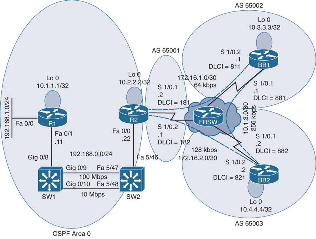
Figure 21-6 Trouble Ticket 6 Topology
You begin by examining the baseline data collected after company A was dual-homed to its two Internet service providers (ISPs). Example 21-59 shows the output from the show ip route command on router R1. Notice that router R1 has a default route in its IP routing table. This default route was learned via OSPF from router R2.
Example 21-59 Baseline Output for Router R1
R1#show ip route
Codes: C - connected, S - static, R - RIP, M - mobile, B - BGP
D - EIGRP, EX - EIGRP external, O - OSPF, IA - OSPF inter area
N1 - OSPF NSSA external type 1, N2 - OSPF NSSA external type 2
E1 - OSPF external type 1, E2 - OSPF external type 2
i - IS-IS, su - IS-IS summary, L1 - IS-IS level-1, L2 - IS-IS level-2
ia - IS-IS inter area, * - candidate default, U - per-user static route
o - ODR, P - periodic downloaded static route
Gateway of last resort is 192.168.0.22 to network 0.0.0.0
10.0.0.0/32 is subnetted, 2 subnets
O 10.2.2.2 [110/2] via 192.168.0.22, 00:05:33, FastEthernet0/1
C 10.1.1.1 is directly connected, Loopback0
C 192.168.0.0/24 is directly connected, FastEthernet0/1
C 192.168.1.0/24 is directly connected, FastEthernet0/0
O*E2 0.0.0.0/0 [110/1] via 192.168.0.22, 00:05:33, FastEthernet0/1
Router R2 was configured for both OSPF and BGP, with the BGP-learned default route being injected into OSPF, and with OSPF-learned routes being redistributed into BGP. Example 21-60 shows the initial IP routing table for router R2. Notice that the next-hop router for the default route is 172.16.1.1 (that is, router BB1).
Example 21-60 Baseline IP Routing Table on Router R2
R2#show ip route
Codes: C - connected, S - static, R - RIP, M - mobile, B - BGP
D - EIGRP, EX - EIGRP external, O - OSPF, IA - OSPF inter area
N1 - OSPF NSSA external type 1, N2 - OSPF NSSA external type 2
E1 - OSPF external type 1, E2 - OSPF external type 2
i - IS-IS, su - IS-IS summary, L1 - IS-IS level-1, L2 - IS-IS level-2
ia - IS-IS inter area, * - candidate default, U - per-user static route
o - ODR, P - periodic downloaded static route
Gateway of last resort is 172.16.1.1 to network 0.0.0.0
172.16.0.0/30 is subnetted, 2 subnets
C 172.16.1.0 is directly connected, Serial1/0.1
C 172.16.2.0 is directly connected, Serial1/0.2
10.0.0.0/8 is variably subnetted, 6 subnets, 3 masks
C 10.2.2.2/32 is directly connected, Loopback0
B 10.1.3.0/30 [20/0] via 172.16.1.1, 00:01:40
B 10.3.3.3/32 [20/0] via 172.16.1.1, 00:01:40
B 10.1.2.0/24 [20/0] via 172.16.1.1, 00:01:40
O 10.1.1.1/32 [110/11] via 192.168.0.11, 00:08:17, FastEthernet0/0
B 10.4.4.4/32 [20/0] via 172.16.2.2, 00:01:40
C 192.168.0.0/24 is directly connected, FastEthernet0/0
O 192.168.1.0/24 [110/11] via 192.168.0.11, 00:08:17, FastEthernet0/0
B* 0.0.0.0/0 [20/0] via 172.16.1.1, 00:01:40
Example 21-61 illustrates the initial OSPF and BGP configuration on router R2.
Example 21-61 Initial Router Configuration on Router R2
R2#show run | begin router
router ospf 1
log-adjacency-changes
network 10.2.2.2 0.0.0.0 area 0
network 192.168.0.0 0.0.0.255 area 0
default-information originate
!
router bgp 65001
no synchronization
bgp log-neighbor-changes
network 172.16.1.0 mask 255.255.255.252
network 172.16.2.0 mask 255.255.255.252
redistribute ospf 1
neighbor 172.16.1.1 remote-as 65002
neighbor 172.16.2.2 remote-as 65003
no auto-summary
Example 21-62 shows the output of the show ip bgp summary command on router R2, which confirms that router R2 resides in BGP autonomous system 65001. The output also confirms BGP adjacencies have been formed with routers BB1 and BB2.
Example 21-62 BGP Configuration Summary on Router R2
R2#show bgp ipv4 unicast summary
BGP router identifier 10.2.2.2, local AS number 65001
BGP table version is 18, main routing table version 18
11 network entries using 1287 bytes of memory
20 path entries using 1040 bytes of memory
8/5 BGP path/bestpath attribute entries using 992 bytes of memory
4 BGP AS-PATH entries using 96 bytes of memory
0 BGP route-map cache entries using 0 bytes of memory
0 BGP filter-list cache entries using 0 bytes of memory
BGP using 3415 total bytes of memory
BGP activity 38/27 prefixes, 75/55 paths, scan interval 60 secs
Neighbor V AS MsgRcvd MsgSent TblVer InQ OutQ Up/Down State/PfxRcd
172.16.1.1 4 65002 102 97 18 0 0 00:02:47 7
172.16.2.2 4 65003 100 97 18 0 0 00:02:47 7
Router BB1 is configured for BGP and is sourcing a default route advertisement. Example 21-63 shows the IP routing table of router BB1.
Example 21-63 Initial IP Routing Table on Router BB1
BB1#show ip route
Codes: C - connected, S - static, R - RIP, M - mobile, B - BGP
D - EIGRP, EX - EIGRP external, O - OSPF, IA - OSPF inter area
N1 - OSPF NSSA external type 1, N2 - OSPF NSSA external type 2
E1 - OSPF external type 1, E2 - OSPF external type 2
i - IS-IS, su - IS-IS summary, L1 - IS-IS level-1, L2 - IS-IS level-2
ia - IS-IS inter area, * - candidate default, U - per-user static route
o - ODR, P - periodic downloaded static route
Gateway of last resort is 0.0.0.0 to network 0.0.0.0
172.16.0.0/30 is subnetted, 2 subnets
C 172.16.1.0 is directly connected, Serial1/0.2
B 172.16.2.0 [20/0] via 10.1.3.2, 00:03:01
10.0.0.0/8 is variably subnetted, 6 subnets, 3 masks
B 10.2.2.2/32 [20/0] via 172.16.1.2, 00:01:59
C 10.1.3.0/30 is directly connected, Serial1/0.1
C 10.3.3.3/32 is directly connected, Loopback0
C 10.1.2.0/24 is directly connected, FastEthernet0/0
B 10.1.1.1/32 [20/11] via 172.16.1.2, 00:01:59
B 10.4.4.4/32 [20/0] via 10.1.3.2, 00:40:10
B 192.168.0.0/24 [20/0] via 172.16.1.2, 00:01:59
B 192.168.1.0/24 [20/11] via 172.16.1.2, 00:01:59
S* 0.0.0.0/0 is directly connected, Null0
Router BB2’s IP routing table, as shown in Example 21-64, is similar to router BB1’s IP routing table. Notice that router BB2 is also sourcing a default route and is advertising it via BGP to router R2. Therefore, router R2 has two paths to reach a default route in its BGP table.
Example 21-64 Initial IP Routing Table on Router BB2
BB2#show ip route
Codes: C - connected, S - static, R - RIP, M - mobile, B - BGP
D - EIGRP, EX - EIGRP external, O - OSPF, IA - OSPF inter area
N1 - OSPF NSSA external type 1, N2 - OSPF NSSA external type 2
E1 - OSPF external type 1, E2 - OSPF external type 2
i - IS-IS, su - IS-IS summary, L1 - IS-IS level-1, L2 - IS-IS level-2
ia - IS-IS inter area, * - candidate default, U - per-user static route
o - ODR, P - periodic downloaded static route
Gateway of last resort is 0.0.0.0 to network 0.0.0.0
172.16.0.0/30 is subnetted, 2 subnets
B 172.16.1.0 [20/0] via 10.1.3.1, 00:03:11
C 172.16.2.0 is directly connected, Serial1/0.2
10.0.0.0/8 is variably subnetted, 6 subnets, 3 masks
B 10.2.2.2/32 [20/0] via 172.16.2.1, 00:02:09
C 10.1.3.0/30 is directly connected, Serial1/0.1
B 10.3.3.3/32 [20/0] via 10.1.3.1, 00:40:10
C 10.1.2.0/24 is directly connected, FastEthernet0/0
B 10.1.1.1/32 [20/11] via 172.16.2.1, 00:02:09
C 10.4.4.4/32 is directly connected, Loopback0
B 192.168.0.0/24 [20/0] via 172.16.2.1, 00:02:09
B 192.168.1.0/24 [20/11] via 172.16.2.1, 00:02:09
S* 0.0.0.0/0 is directly connected, Null0
As shown earlier, in Example 21-60, router R2 preferred the 64-Kbps link to router BB1 to reach a default route, as opposed to the 128-Kbps link to router BB2. Therefore, the outbound routing from router R2 is suboptimal.
Also, the inbound routing, coming into the enterprise via router R2, is suboptimal. To illustrate this point, consider Example 21-65, which shows the BGP table on router BB1. Notice that router BB1 prefers a next-hop router of router R2 to reach the 10.1.1.1/32 network, which resides inside the enterprise network (that is, the network consisting of routers R1 and R2). Using a next-hop router of R2 would force traffic over the 64-Kbps link rather than sending traffic from router BB1 over the 256-Kbps link to router BB2, and then over the 128-Kbps link to router R2, and finally across the Fast Ethernet connection to router R1.
Example 21-65 BGP Forwarding Table on Router BB1
BB1#show bgp ipv4 unicast
BGP table version is 130, local router ID is 10.3.3.3
Status codes: s suppressed, d damped, h history, * valid, > best, i - internal,
r RIB-failure, S Stale
Origin codes: i - IGP, e - EGP, ? - incomplete
Network Next Hop Metric LocPrf Weight Path
* 0.0.0.0 10.1.3.2 0 0 65003 i
*> 0.0.0.0 0 32768 i
* 10.1.1.1/32 10.1.3.2 0 65003 65001 ?
*> 172.16.1.2 11 0 65001 ?
* 10.1.2.0/24 10.1.3.2 0 0 65003 i
*> 0.0.0.0 0 32768 i
* 10.1.3.0/30 10.1.3.2 0 0 65003 i
*> 0.0.0.0 0 32768 i
* 10.2.2.2/32 10.1.3.2 0 65003 65001 ?
*> 172.16.1.2 0 0 65001 ?
*> 10.3.3.3/32 0.0.0.0 0 32768 i
* 10.4.4.4/32 172.16.1.2 0 65001 65003 i
*> 10.1.3.2 0 0 65003 i
* 172.16.1.0/30 172.16.1.2 0 0 65001 i
*> 0.0.0.0 0 32768 i
* 172.16.2.0/30 172.16.1.2 0 0 65001 i
*> 10.1.3.2 0 0 65003 i
* 192.168.0.0 10.1.3.2 0 65003 65001 ?
*> 172.16.1.2 0 0 65001 ?
* 192.168.1.0 10.1.3.2 0 65003 65001 ?
*> 172.16.1.2 11 0 65001
As you formulate your solution to correct the inbound and outbound path selection issues, you should limit your configuration to router R2. The reason for this limitation is that routers BB1 and BB2 are acting as ISP routers. In a real-world environment, the administrator of an enterprise network would not have privileges to configure the ISP routers.
BGP has multiple attributes that can be manipulated to influence path selection. The suggested solution, however, focuses on how the BGP local preference attribute can influence the outbound path selection and how the BGP AS_PATH attribute can influence the inbound path selection. You can configure route maps to set these BGP attributes. If you choose to base your solution on local preference and AS_PATH attributes, Table 21-1 provides a syntax reference that might be helpful.
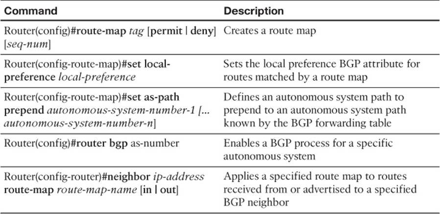
Table 21-1 Configuring AS_PATH and Local Preference BGP Attributes
Take a moment to look through the provided show command output. Then, on a separate sheet of paper, create a plan for correcting the suboptimal path selection.
Suggested Solution
Local preference values can be applied to routes coming into a router. This can cause that router to make its outbound routing decisions based on those local preference values. Higher local preference values are preferred over lower local preference values.
An autonomous system path (that is, a listing of the autonomous systems that must be transited to reach a specific destination network) advertised to a neighbor can influence the BGP path selection of that neighbor. Specifically, BGP can make routing decisions based on the smallest number of autonomous systems that must be crossed to reach a destination network. Using a route map, you can prepend one or more additional instances of your local autonomous system to the AS_PATH advertised to a router’s neighbor, thereby making that path appear less attractive to your neighbor.
Therefore, the suggested solution configures local preference values for routes advertised into router R2 from routers BB1 and BB2 to prefer routes being advertised via router BB2. Example 21-66 shows this configuration, which influences outbound path selection.
Example 21-66 Local Preference Configuration on Router R2
R2(config)#route-map LOCALPREF-BB1
R2(config-route-map)#set local-preference 100
R2(config-route-map)#exit
R2(config)#route-map LOCALPREF-BB2
R2(config-route-map)#set local-preference 200
R2(config-route-map)#exit
R2(config)#router bgp 65001
R2(config-router)#neighbor 172.16.1.1 route-map LOCALPREF-BB1 in
R2(config-router)#neighbor 172.16.2.2 route-map LOCALPREF-BB2 in
R2(config-router)#exit
To influence inbound path selection, this suggested solution configures a route map to prepend two additional instances of autonomous system 65001 to routes being advertised via BGP from router R2 to router BB1. Example 21-67 shows this configuration, which causes router BB1 to use router BB2 as a next-hop router when sending traffic into the enterprise network. It does this because the path via router BB2 appears to be fewer autonomous system hops away from the enterprise networks.
Example 21-67 AS_PATH Configuration on Router R2
R2(config)#route-map ASPATH 10
R2(config-route-map)#set as-path prepend 65001 65001
R2(config-route-map)#exit
R2(config)#router bgp 65001
R2(config-router)#neighbor 172.16.1.1 route-map ASPATH out
R2(config-router)#end
Example 21-68 confirms that router R2 now prefers router BB2 (that is, a next-hop IP address of 172.16.2.2) to reach the default network.
Example 21-68 Preferred Path of Router R2 to Backbone Networks
R2#show bgp ipv4 unicast
BGP table version is 16, local router ID is 10.2.2.2
Status codes: s suppressed, d damped, h history, * valid, > best, i - internal,
r RIB-failure, S Stale
Origin codes: i - IGP, e - EGP, ? - incomplete
Network Next Hop Metric LocPrf Weight Path
* 0.0.0.0 172.16.1.1 0 100 0 65002 i
*> 172.16.2.2 0 200 0 65003 i
*> 10.1.1.1/32 192.168.0.11 11 32768 ?
* 10.1.2.0/24 172.16.1.1 0 100 0 65002 i
*> 172.16.2.2 0 200 0 65003 i
* 10.1.3.0/30 172.16.1.1 0 100 0 65002 i
*> 172.16.2.2 0 200 0 65003 i
*> 10.2.2.2/32 0.0.0.0 0 32768 ?
* 10.3.3.3/32 172.16.1.1 0 100 0 65002 i
*> 172.16.2.2 200 0 65003 65002 i
* 10.4.4.4/32 172.16.1.1 100 0 65002 65003 i
*> 172.16.2.2 0 200 0 65003 i
*> 172.16.1.0/30 0.0.0.0 0 32768 i
* 172.16.1.1 0 100 0 65002 i
* 172.16.2.2 200 0 65003 65002 i
*> 172.16.2.0/30 0.0.0.0 0 32768 i
* 172.16.1.1 100 0 65002 65003 i
* 172.16.2.2 0 200 0 65003 i
*> 192.168.0.0 0.0.0.0 0 32768 ?
*> 192.168.1.0 192.168.0.11 11 32768
Example 21-69 confirms that router BB1 will not prefer to send traffic to the enterprise network (that is, to routers R1 and R2) via router R2, but rather via router BB2. Notice from the output that more autonomous system hops appear to be required to reach enterprise networks via router R2 (that is, 172.16.1.2) compared to router BB2 (that is, 10.1.3.2). Therefore, router BB1 prefers to send traffic into the enterprise network via router BB2, as opposed to router R2.
Example 21-69 Preferred Path of Router BB1 to Enterprise Networks
BB1#show bgp ipv4 unicast
BGP table version is 142, local router ID is 10.3.3.3
Status codes: s suppressed, d damped, h history, * valid, > best, i - internal,
r RIB-failure, S Stale
Origin codes: i - IGP, e - EGP, ? - incomplete
Network Next Hop Metric LocPrf Weight Path
* 0.0.0.0 172.16.1.2 0 65001 65001 65001 65003 i
* 10.1.3.2 0 0 65003 i
*> 0.0.0.0 0 32768 i
*> 10.1.1.1/32 10.1.3.2 0 65003 65001 ?
* 172.16.1.2 11 0 65001 65001 65001 ?
* 10.1.2.0/24 172.16.1.2 0 65001 65001 65001 65003 i
* 10.1.3.2 0 0 65003 i
*> 0.0.0.0 0 32768 i
* 10.1.3.0/30 172.16.1.2 0 65001 65001 65001 65003 i
* 10.1.3.2 0 0 65003 i
*> 0.0.0.0 0 32768 i
*> 10.2.2.2/32 10.1.3.2 0 65003 65001 ?
* 172.16.1.2 0 0 65001 65001 65001 ?
*> 10.3.3.3/32 0.0.0.0 0 32768 i
* 10.4.4.4/32 172.16.1.2 0 65001 65001 65001 65003 i
*> 10.1.3.2 0 0 65003 i
* 172.16.1.0/30 172.16.1.2 0 0 65001 65001 65001 i
*> 0.0.0.0 0 32768 i
* 172.16.2.0/30 172.16.1.2 0 0 65001 65001 65001 i
*> 10.1.3.2 0 0 65003 i
*> 192.168.0.0 10.1.3.2 0 65003 65001 ?
* 172.16.1.2 0 0 65001 65001 65001 ?
*> 192.168.1.0 10.1.3.2 0 65003 65001 ?
* 172.16.1.2 11 0 65001 65001 65001
Trouble Ticket 7
You receive the following trouble ticket:
A new administrator for company A has forgotten the enable secret password assigned to router R1 and can no longer log in. Also, when this administrator connects to router R2 via Telnet, the connection is timed out after only 1 second. The administrator reports this short timeout does not give him sufficient time to correct the configuration. Also, the administrator configured an access list on router R2 to prevent anyone on the backbone (that is, connections coming in to router R2 via the Frame Relay network) from connecting to the Loopback 0 interfaces on routers R1 or R2 via Telnet. However, the access list does not seem to be working.
This trouble ticket references the topology shown in Figure 21-7.
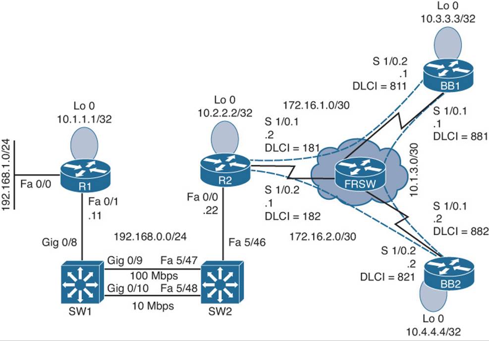
Figure 21-7 Trouble Ticket 7 Topology
The trouble ticket identified the following three issues:
![]() A forgotten enable secret password
A forgotten enable secret password
![]() An exec-timeout parameter set too low
An exec-timeout parameter set too low
![]() An ACL misconfiguration
An ACL misconfiguration
The sections that follow address each issue individually.
Issue 1: Forgotten Enable Secret Password
The first issue to be addressed by this trouble ticket is password recovery. The administrator reportedly forgot the enable secret password for router R1, which is a Cisco 2900 series router.
On a separate sheet of paper, write out the steps you would go through to perform password recovery on this router. If you are not familiar with password recovery steps, you might need to research password recovery at Cisco.com.
Issue 1: Suggested Solution
To begin the password recovery process on router R1, the router was rebooted, and during the first few seconds of the router booting, a Break was sent from the terminal emulator to the router. The Break caused the ROM Monitor prompt (that is, rommon) to appear on router R1’s console.
The configuration register was set to 0x2142 with the command confreg 0x2142. Setting the configuration register to this value causes the router to ignore its startup configuration when the router boots. The router was then rebooted by issuing the reset command at the rommon prompt.
Because the router ignored the startup configuration, after the router booted, a prompt was presented, asking the administrator whether he wanted to go through the setup dialog. A no was entered at this prompt. The enable command was entered to go into privileged configuration mode. From privileged mode, the startup configuration, stored in the router’s NVRAM, was merged with the existing running configuration using the command copy star run. This command does not replace the running configuration with the startup configuration. Rather, these two configurations are merged. After this merger, all the physical interfaces were administratively shut down. Therefore, the no shutdown command was entered for interfaces Fast Ethernet 0/0 and Fast Ethernet 0/1.
The enable secret password was reset to cisco using the command enable secret cisco. Next, the configuration register was set back to its normal value of 0x2102 with the command config-register 0x2102. The running configuration was copied to the startup configuration with the commandcopy run star. The router was then rebooted with the reload command. After the router rebooted, the administrator could access the router’s privileged mode using an enable secret password of cisco. Example 21-70 demonstrates this password-recovery procedure.
Example 21-70 Performing Password Recovery on Router R1
System Bootstrap, Version 15.0(1r)M1, RELEASE SOFTWARE (fc1)
Copyright (c) 2009 by cisco Systems, Inc.
C2900 platform with 524288 Kbytes of main memory
...BREAK SEQUENCE SENT...
monitor: command "boot" aborted due to user interrupt
rommon 1 > confreg 0x2142
You must reset or power cycle for new config to take effect
rommon 2 > reset
...OUTPUT OMITTED...
---- System Configuration Dialog ----
Would you like to enter the initial configuration dialog? [yes/no]: no
Press RETURN to get started!
...OUTPUT OMITTED...
Router>enable
Router#copy star run
Destination filename [running-config]?
...OUTPUT OMITTED...
R1(config)#enable secret cisco
R1(config)#config-register 0x2102
R1(config)#interface fa 0/1
R1(config-if)#no shut
R1(config-if)#interface fa 0/0
R1(config-if)#no shut
R1(config-if)#end
*Mar 3 12:43:26.016: %SYS-5-CONFIG_I: Configured from console by console
R1#copy run star
Destination filename [startup-config]?
Building configuration...
[OK]
R1#reload
Proceed with reload? [confirm]
...OUTPUT OMITTED...
Press RETURN to get started!
R1>
R1>enable
Password:cisco
R1#
Issue 2: An exec-timeout Parameter Set Too Low
The second issue addressed in this trouble ticket is recovering from a misconfiguration on router R2, which causes a Telnet session to time out after only 1 second of inactivity. The challenge with such a misconfiguration is that when an administrator telnets to the router to correct the configuration, he might be logged out if he pauses for as little as a single second.
Example 21-71 shows router R2’s misconfiguration. Note the exec-timeout 0 1 command. This command causes a user that connected via a vty line to be timed out after only one second of inactivity.
Example 21-71 Incorrect exec-timeout Configuration on Router R2
R2#show run | begin line vty 0 4
line vty 0 4
exec-timeout 0 1
password cisco
login
On a separate sheet of paper, write out how you would approach this seemingly paradoxical situation, where you have to log in to the router to correct the configuration, while you will be logged out of the router with only a single second’s pause.
Issue 2: Suggested Solution
One fix to this issue is to continuously tap on the keyboard’s down arrow with one hand, while using the other hand to enter the commands required to correct the exec-timeout misconfiguration. Example 21-72 shows the commands entered to set the exec-timeout parameter such that a Telnet session times out after 5 minutes of inactivity. You could also attach to the console or aux port on the device and change these parameters for the telnet session.
Example 21-72 Correcting an exec-timeout Misconfiguration
R2#conf term
R2(config)#line vty 0 4
R2(config-line)#exec-timeout 5 0
Issue 3: ACL Misconfiguration
This trouble ticket’s final troubleshooting issue was an ACL misconfiguration. The goal of the ACL on router R2 was to prevent Telnet traffic coming in from the backbone (that is, coming in over subinterfaces Serial 1/0.1 or Serial 1/0.2) destined for the loopback interface on router R1 or R2 (that is, IP addresses 10.1.1.1 or 10.2.2.2). Example 21-73 shows the ACL configuration on router R2.
Example 21-73 Baseline ACL Configuration on Router R2
R2#show run
...OUTPUT OMITTED...
interface s1/0.1
ip access-group 100 out
!
interface s1/0.2
ip access-group 100 out
!
access-list 100 deny tcp any host 10.1.1.1 eq telnet
access-list 100 deny tcp any host 10.2.2.2 eq telnet
access-list 100 permit ip any any
Based on the trouble ticket and the proceeding show command output, on a separate sheet of paper, formulate your strategy for resolving the reported issue.
Issue 3: Suggested Solution
Upon examination, the ACL (an extended IP ACL numbered 100) on router R2 appears to be configured correctly. However, ACL 100 was applied in the outbound direction on router R2’s Frame Relay subinterfaces. ACL 100 should have been applied in the incoming direction on these subinterfaces. This suggested solution replaces the incorrect ip access-group commands, as shown in Example 21-74.
Example 21-74 Correcting the Application of ACL 100 on Router R2
R2#conf term
R2(config)#interface s1/0.1
R2(config-if)#no ip access-group 100 out
R2(config-if)#ip access-group 100 in
R2(config-if)#interface s1/0.2
R2(config-if)#no ip access-group 100 out
R2(config-if)#ip access-group 100 in
After making the previous update, Telnet connections destined for the Loopback interfaces on routers R1 and R2, coming into router R2 over its Frame Relay subinterfaces are now denied.
Trouble Ticket 8
You receive the following trouble ticket:
Company A is dual-homed out to the Internet (that is, routers BB1 and BB2, where each router represents a different ISP). Inside IP addresses in the 192.168.0.0/24 subnet should be translated into the IP address of interface Serial 1/0.1 on router R2, whereas inside IP addresses in the 192.168.1.0/24 subnet should be translated into the IP address of interface Serial 1/0.2 on router R2. Router R2’s Network Address Translation (NAT) table shows two active translations. The configuration, therefore, seems to be partially working. However, no additional NAT translations can be set up.
This trouble ticket references the topology shown in Figure 21-8.
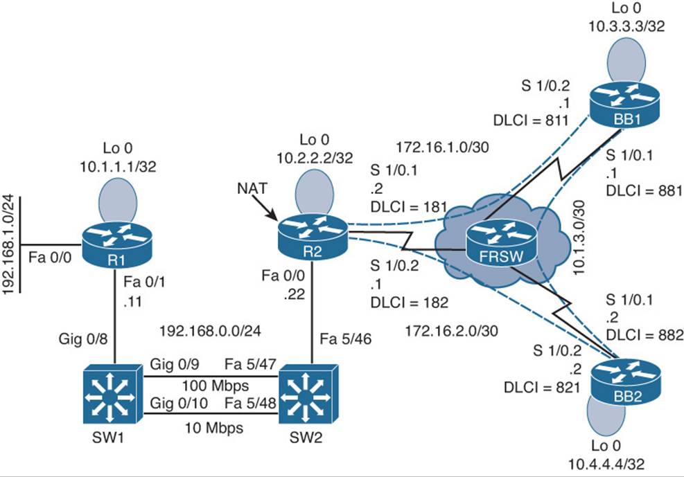
Figure 21-8 Trouble Ticket 8 Topology
Because router R2 is the one configured to perform NAT, the following show and debug command output collects information about the NAT configuration of router R2. Initially, notice the output of the show ip nat translations command issued on router R2, as shown in Example 21-75.
Example 21-75 show ip nat translations Command Output on Router R2
R2#show ip nat translations
Pro Inside global Inside local Outside local Outside global
icmp 172.16.1.2:7 192.168.0.11:7 10.4.4.4:7 10.4.4.4:7
icmp 172.16.2.1:512 192.168.1.50:512 10.1.3.2:512 10.1.3.2:512
The debug ip nat command is issued next. The output provided in Example 21-76 shows NAT translations as they occur.
Example 21-76 debug ip nat Command Output on Router R2
R2#debug ip nat
IP NAT debugging is on
*Mar 1 00:34:16.651: NAT*: s=10.4.4.4, d=172.16.1.2->192.168.0.11 [4092]
*Mar 1 00:34:16.711: NAT*: s=192.168.0.11->172.16.1.2, d=10.4.4.4 [4093]
*Mar 1 00:34:16.843: NAT*: s=10.4.4.4, d=172.16.1.2->192.168.0.11 [4093]
*Mar 1 00:34:16.939: NAT*: s=192.168.0.11->172.16.1.2, d=10.4.4.4 [4094]
*Mar 1 00:34:16.963: NAT*: s=192.168.1.50->172.16.2.1, d=10.1.3.2 [13977]
*Mar 1 00:34:17.115: NAT*: s=10.4.4.4, d=172.16.1.2->192.168.0.11 [4094]
*Mar 1 00:34:17.163: NAT*: s=192.168.0.11->172.16.1.2, d=10.4.4.4 [4095]
*Mar 1 00:34:17.187: NAT*: s=10.1.3.2, d=172.16.2.1->192.168.1.50 [13977]
*Mar 1 00:34:17.315: NAT*: s=10.4.4.4, d=172.16.1.2->192.168.0.11 [4095]
The trouble ticket indicated that no more than two active translations can be supported at any time. To verify that symptom, Example 21-77 shows an attempt to send a ping from router R1. Notice that the ping response indicates that 10.4.4.4 is unreachable.
Example 21-77 Attempting to Ping 10.4.4.4 from Router R1
R1#ping 10.4.4.4
Type escape sequence to abort.
Sending 5, 100-byte ICMP Echos to 10.4.4.4, timeout is 2 seconds:
U.U.U
Success rate is 0 percent (0/5)
To determine whether the inability to ping 10.4.4.4 is a result of NAT or some other issue, the NAT translation table on router R2 is cleared with the clear ip nat translation * command. Then, with the NAT translation table of router R2 cleared, Example 21-78 shows the result of another ping from router R1 to 10.4.4.4. This time, the ping is successful.
Example 21-78 Reattempting to Ping 10.4.4.4 from Router R1
R1#ping 10.4.4.4
Type escape sequence to abort.
Sending 5, 100-byte ICMP Echos to 10.4.4.4, timeout is 2 seconds:
!!!!!
Success rate is 100 percent (5/5), round-trip min/avg/max = 72/137/240 ms
Example 21-79 shows the NAT translation table of router R2 after R1 performs a ping to 10.4.4.4.
Example 21-79 NAT Translation Table of Router R2
R2#show ip nat translations
Pro Inside global Inside local Outside local Outside global
icmp 172.16.1.2:10 192.168.0.11:10 10.4.4.4:10 10.4.4.4:10
The output from the previous commands confirms that router R2 is capable of supporting only two simultaneous NAT translations. This symptom often indicates that a router’s NAT pool (or pools in this case) is depleted, perhaps because the NAT configuration did not use the overload option in the ip nat inside source command. Recall that the overload option enables PAT, which allows multiple inside local IP addresses to share a common inside global IP address.
Example 21-80 shows the running configuration of router R2. Interestingly, both the ip nat inside source commands have the overload option, thus eliminating that as a potential cause for the reported issue.
Example 21-80 Running Configuration of Router R2
R2#show run
...OUTPUT OMITTED...
hostname R2
!
interface Loopback0
ip address 10.2.2.2 255.255.255.255
!
interface FastEthernet0/0
ip address 192.168.0.22 255.255.255.0
ip nat inside
!
interface Serial1/0
no ip address
encapsulation frame-relay
!
interface Serial1/0.1 point-to-point
ip address 172.16.1.2 255.255.255.252
ip nat outside
frame-relay interface-dlci 181
!
interface Serial1/0.2 point-to-point
ip address 172.16.2.1 255.255.255.252
ip nat outside
ip virtual-reassembly
frame-relay interface-dlci 182
!
router ospf 1
network 0.0.0.0 255.255.255.255 area 0
!
ip nat translation max-entries 2
ip nat inside source list 1 interface Serial1/0.2 overload
ip nat inside source list 2 interface Serial1/0.1 overload
!
access-list 1 permit 192.168.1.0 0.0.0.255
access-list 2 permit 192.168.0.0 0.0.0.255
!
...OUTPUT OMITTED...
Based on the output of the previous show and debug commands, on a separate sheet of paper, write out what you believe to be the underlying issue and how you would resolve it.
Suggested Solution
In the running configuration of router R2, you might have noticed the ip nat translation max-entries 2 command. This command limits the maximum number of NAT translations on router R2 to only two.
To resolve this issue, this configuration command is removed, as shown in Example 21-81.
Example 21-81 Removing the ip nat translation max-entries 2 Command of Router R2
R2#conf term
Enter configuration commands, one per line. End with CNTL/Z.
R2(config)#no ip nat translation max-entries 2
R2(config)#end
To demonstrate that the removal of the ip nat translation max-entries 2 command did indeed resolve the reported issue, three NAT translations were established across router R2, as confirmed in Example 21-82.
Example 21-82 Confirming That Router R2 Supports Multiple NAT Translations
R2#show ip nat translations
Pro Inside global Inside local Outside local Outside global
icmp 172.16.1.2:12 192.168.0.11:12 10.4.4.4:12 10.4.4.4:12
icmp 172.16.2.1:13 192.168.1.11:13 10.3.3.3:13 10.3.3.3:13
icmp 172.16.2.1:512 192.168.1.50:512 10.1.3.2:512 10.1.3.2:512
Trouble Ticket 9
You receive the following trouble ticket:
Company A recently added IPv6 addressing to its existing IPv4 addressing. OSPFv3 is the protocol being used to route the IPv6 traffic. Although the configuration was originally functional, now several OSPFv3 adjacencies are not forming. Full IPv6 reachability throughout the topology needs to be established.
This trouble ticket references the topology shown in Figure 21-9.
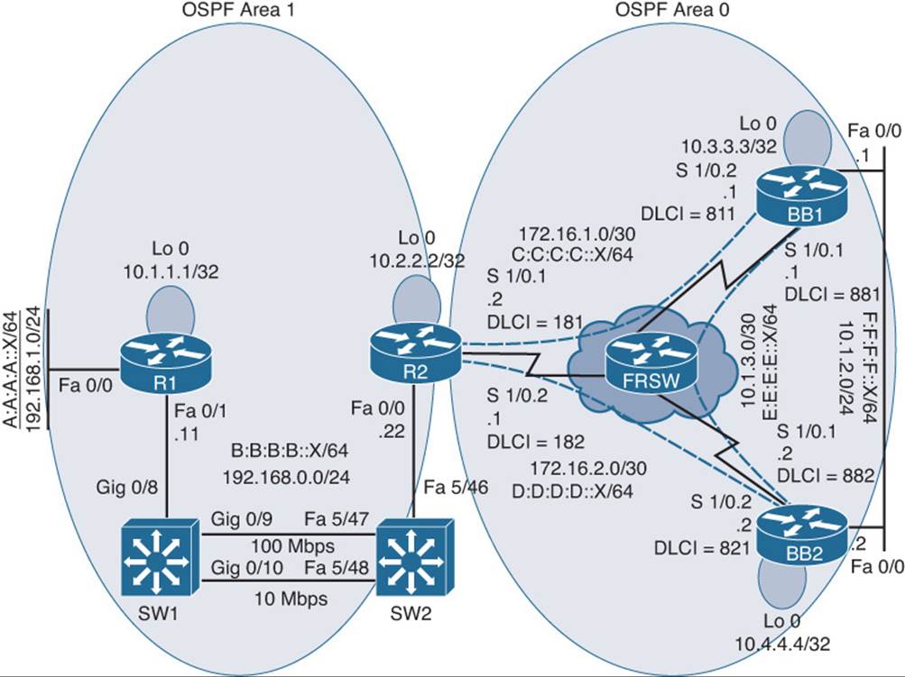
Figure 21-9 Trouble Ticket 9 Topology
The trouble ticket indicates that several adjacencies are not being formed. So, you decide to start your troubleshooting efforts on router R1 and check its adjacency with router R2, and then check the adjacencies between R2 and BB1 and BB2. Finally, you will check the adjacencies between BB1 and BB2.
Issue 1: Adjacency Between Routers R1 and R2
Example 21-83 shows the data collected from router R1.
Example 21-83 Troubleshooting Data Collection on Router R1
R1#show ipv6 ospf neighbor
R1#debug ipv6 ospf adj
OSPFv3 adjacency events debugging is on
R1#debug ipv6 ospf hello
OSPFv3 hello events debugging is on
R1#u all
All possible debugging has been turned off
R1#show run
...OUTPUT OMITTED...
hostname R1
!
ipv6 unicast-routing
ipv6 cef
!
interface Loopback0
ip address 10.1.1.1 255.255.255.255
!
interface FastEthernet0/0
ip address 192.168.1.11 255.255.255.0
ipv6 address A:A:A:A::11/64
ipv6 ospf 100 area 1
!
interface FastEthernet0/1
ip address 192.168.0.11 255.255.255.0
ipv6 address B:B:B:B::11/64
ipv6 ospf 100 area 1
!
ipv6 router ospf 100
!
...OUTPUT OMITTED...
R1#show ipv6 ospf interface fa 0/1
FastEthernet0/1 is up, line protocol is up
Link Local Address FE80::209:B7FF:FEFA:D1E1, Interface ID 4
Area 1, Process ID 100, Instance ID 0, Router ID 192.168.1.11
Network Type BROADCAST, Cost: 1
Transmit Delay is 1 sec, State DR, Priority 1
Designated Router (ID) 192.168.1.11, local address FE80::209:B7FF:FEFA:D1E1
No backup designated router on this network
Timer intervals configured, Hello 10, Dead 40, Wait 40, Retransmit 5
Hello due in 00:00:03
Index 1/2/2, flood queue length 0
Next 0x0(0)/0x0(0)/0x0(0)
Last flood scan length is 1, maximum is 2
Last flood scan time is 0 msec, maximum is 0 msec
Neighbor Count is 0, Adjacent neighbor count is 0
Suppress hello for 0 neighbor(s)
Notice that router R1 has not formed an adjacency with router R2 and there are no Hello packets being exchanged between the two routers. Example 21-84 shows the data collected from router R2.
Example 21-84 Troubleshooting Data Collection on Router R2
R2#show ipv6 ospf neighbor
R2#debug ipv6 ospf adj
OSPFv3 adjacency events debugging is on
R2#u all
All possible debugging has been turned off
R2#show run
...OUTPUT OMITTED...
hostname R2
!
ipv6 unicast-routing
ipv6 cef
!
interface Loopback0
ip address 10.2.2.2 255.255.255.255
!
interface FastEthernet0/0
ip address 192.168.0.22 255.255.255.0
ipv6 address B:B:B:B::22/64
ipv6 ospf hello-interval 60
ipv6 ospf 1 area 1
!
interface Serial1/0
no ip address
encapsulation frame-relay
!
interface Serial1/0.1 point-to-point
ip address 172.16.1.2 255.255.255.252
ipv6 address C:C:C:C::2/64
ipv6 ospf 1 area 0
frame-relay interface-dlci 181
!
interface Serial1/0.2 point-to-point
ip address 172.16.2.1 255.255.255.252
ipv6 address D:D:D:D::1/64
ipv6 ospf network point-to-multipoint
ipv6 ospf 1 area 0
frame-relay interface-dlci 182
!
ipv6 router ospf 1
passive-interface default
!
...OUTPUT OMITTED...
Based on the output provided in Examples 21-83 and 21-84, hypothesize why routers R1 and R2 are not forming an adjacency. On a separate sheet of paper, write out your suggested solution to correct the issue.
Issue 1: Suggested Solution
Notice in Example 21-84 that router R2’s hello timer on the Fast Ethernet 0/0 interface was set to a nondefault value, whereas the other end of the link was still set to the default. Also, router R2 had its OSPFv3 process configured with the passive-interface default command, which prevented any of router R2’s interfaces from forming OSPFv3 adjacencies. Example 21-85 shows the correction of these configuration issues on router R2.
Example 21-85 Correcting Router R2’s Hello Timer and Passive-Interface Configuration
R2#conf term
Enter configuration commands, one per line. End with CNTL/Z.
R2(config)#int fa 0/0
R2(config-if)#no ipv6 ospf hello-interval 60
R2(config-if)#exit
R2(config)#ipv6 router ospf 1
R2(config-rtr)#no passive-interface default
Issue 2: Adjacency Between Routers R2 and BB2
After implementing the fix shown in Example 21-85, router R2 successfully forms OSPF adjacencies with routers R1 and BB1. However, an adjacency is not successfully formed with router BB2. Example 21-86 shows the output of the show ipv6 ospf interface s1/0.2 command issued on router BB2. This command was issued to view the OSPFv3 configuration of router BB2’s Serial 1/0.2 subinterface, which is the subinterface used to connect to router R2. You compare this to R2s OSPF configuration on Serial 1/0.2 in Example 21-84.
Example 21-86 Viewing Router BB2’s OSPFv3 Configuration on Subinterface Serial 1/0.2
BB2#show ipv6 ospf interface s1/0.2
Serial1/0.2 is up, line protocol is up
Link Local Address FE80::C200:8FF:FE2C:0, Interface ID 14
Area 0, Process ID 1, Instance ID 0, Router ID 10.4.4.4
Network Type POINT_TO_POINT, Cost: 64
Transmit Delay is 1 sec, State POINT_TO_POINT,
...OUTPUT OMITTED...
BB2#show ipv6 ospf neighbor
Based on router R2’s configuration (shown in Example 21-84) and the output shown in Example 21-86, determine why an OSPF adjacency is not being formed between routers R2 and BB2. Again, on a separate sheet of paper, write out your suggested solution.
Issue 2: Suggested Solution
Router R2’s OSPF network type on subinterface Serial 1/0.2 was set to point-to-multipoint; the other end of the link was the default network type of point-to-point. Example 21-87 shows the correction of router R2’s misconfiguration.
Example 21-87 Correcting Router R2’s OSPF Network Type
R2#conf term
Enter configuration commands, one per line. End with CNTL/Z.
R2(config)#int s1/0.2
R2(config-subif)#no ipv6 ospf network point-to-multipoint
R2(config-subif)#exit
At this point in the troubleshooting process, routers R1 and R2 have formed adjacencies. In addition, router R2 has formed adjacencies with routers BB1 and BB2. The output in Example 21-88 confirms the establishment of these adjacencies.
Example 21-88 Confirming Router R2’s OSPF Adjacencies
R2#show ipv6 ospf neighbor
Neighbor ID Pri State Dead Time Interface ID Interface
10.4.4.4 1 FULL/ - 00:00:36 14 Serial1/0.2
10.3.3.3 1 FULL/ - 00:00:36 14 Serial1/0.1
192.168.1.11 1 FULL/DR 00:00:39 4 FastEthernet0/0
Issue 3: Adjacency Between Routers BB1 and BB2
As shown in the output provided in Example 21-89, router BB1 has formed an adjacency with router BB2 over router BB1’s Fast Ethernet 0/0 interface. However, an adjacency has not been successfully formed with router BB2 over router BB1’s Serial 1/0.1 subinterface.
Example 21-89 Determining Router BB1’s Adjacencies
BB1#show ipv6 ospf neigh
Neighbor ID Pri State Dead Time Interface ID Interface
10.2.2.2 1 FULL/ - 00:00:37 13 Serial1/0.2
10.4.4.4 1 DOWN/ - - 13 Serial1/0.1
10.4.4.4 1 FULL/DR 00:00:34 4 FastEthernet0/0
To investigate why an OSPF adjacency is not forming with router BB2 via router BB1’s Serial 1/0.1 subinterface, the debug ipv6 ospf adj and debug ipv6 ospf hello commands were issued on router BB1, as shown in Example 21-90.
Example 21-90 Debugging OSPFv3 Adjacency and Hello Events on Router BB1
BB1#debug ipv6 ospf adj
OSPFv3 adjacency events debugging is on
BB1#debug ipv6 ospf hello
OSPFv3 hello events debugging is on
BB1#
*Mar 1 00:19:24.707: OSPFv3: Rcv DBD from 10.4.4.4 on Serial1/0.1 seq 0x1AEF opt
0x0013 flag 0x7 len 28 mtu 1500 state EXSTART
*Mar 1 00:19:24.707: OSPFv3: Nbr 10.4.4.4 has larger interface MTU
*Mar 1 00:19:25.015: OSPFv3: Rcv hello from 10.2.2.2 area 0 from Serial1/0.2
FE80::C201:8FF:FE2C:0 interface ID 13
*Mar 1 00:19:25.019: OSPFv3: End of hello processing
*Mar 1 00:19:28.583: OSPFv3: Send hello to FF02::5 area 0 on Serial1/0.2 from
FE80::C202:8FF:FE98:0 interface ID 14
*Mar 1 00:19:28.647: OSPFv3: Rcv hello from 10.4.4.4 area 0 from Serial1/0.1
FE80::C200:8FF:FE2C:0 interface ID 13
*Mar 1 00:19:28.651: OSPFv3: End of hello processing
*Mar 1 00:19:28.983: OSPFv3: Send hello to FF02::5 area 0 on FastEthernet0/0
from FE80::C202:8FF:FE98:0 interface ID 4
*Mar 1 00:19:29.215: OSPFv3: Rcv hello from 10.4.4.4 area 0 from FastEthernet0/0
FE80::C200:8FF:FE2C:0 interface ID 4
*Mar 1 00:19:29.219: OSPFv3: End of hello processing
BB1# u all
All possible debugging has been turned off
Because your troubleshooting on router BB1 is focused on BB1’s Serial 1/0.1 subinterface, the show ipv6 interface s1/0.1 command was issued, the output for which appears in Example 21-91.
Example 21-91 Viewing the IPv6 Configuration on Router BB1’s Serial 1/0.1 Subinterface
BB1#show ipv6 interface s1/0.1
Serial1/0.1 is up, line protocol is up
IPv6 is enabled, link-local address is FE80::C202:8FF:FE98:0
Global unicast address(es):
E:E:E:E::1, subnet is E:E:E:E::/64
Joined group address(es):
FF02::1
FF02::2
FF02::5
FF02::1:FF00:1
FF02::1:FF98:0
MTU is 1400 bytes
ICMP error messages limited to one every 100 milliseconds
ICMP redirects are enabled
ND DAD is enabled, number of DAD attempts: 1
ND reachable time is 30000 milliseconds
Hosts use stateless autoconfig for addresses.
Based on the output provided in Examples 21-90 and 21-91, determine why router BB1 is failing to form an OSPF adjacency with router BB2, via router BB1’s Serial 1/0.1 subinterface. On a separate sheet of paper, write out your proposed solution to this issue.
Issue 3: Suggested Solution
The debug output shown in Example 21-90 indicates that router BB1’s neighbor (that is, 10.4.4.4) reachable over subinterface Serial 1/0.1 has a larger maximum transmission unit (MTU) than router BB1’s Serial 1/0.1 subinterface. The output in Example 21-91 indicates that router BB1’s Serial 1/0.1 subinterface has an MTU of 1400 bytes. This is less than the default value of 1500 bytes for this router. Example 21-92 shows how this MTU value was reset to its default value.
Example 21-92 Correcting the MTU on Router BB1’s Serial 1/0.1 Subinterface
BB1#conf term
Enter configuration commands, one per line. End with CNTL/Z.
BB1(config)#int s1/0.1
BB1(config-subif)#ipv6 mtu 1500
*Mar 1 00:20:00.019: %OSPFv3-5-ADJCHG: Process 1, Nbr 10.4.4.4 on Serial1/0.1 from LOADING to FULL, Loading Done
BB1(config-subif)#end
Notice, in Example 21-92, that an adjacency with router BB2 (that is, 10.4.4.4) was formed over router BB1’s Serial 1/0.1 subinterface after setting the subinterface’s MTU size to the default of 1500 bytes. Examples 21-93 and 21-94 further confirm that routers BB1 and BB2 have formed all appropriate adjacencies with their OSPF neighbors.
Example 21-93 Router BB1’s OSPF Adjacencies
BB1#show ipv6 ospf neighbor
Neighbor ID Pri State Dead Time Interface ID Interface
10.2.2.2 1 FULL/ - 00:00:37 13 Serial1/0.2
10.4.4.4 1 FULL/ - 00:00:30 13 Serial1/0.1
10.4.4.4 1 FULL/DR 00:00:31 4 FastEthernet0/0
Example 21-94 Router BB2’s OSPF Adjacencies
BB2#show ipv6 ospf neighbor
Neighbor ID Pri State Dead Time Interface ID Interface
10.2.2.2 1 FULL/ - 00:00:37 14 Serial1/0.2
10.3.3.3 1 FULL/ - 00:00:37 13 Serial1/0.1
10.3.3.3 1 FULL/BDR 00:00:31 4 FastEthernet0/0
To confirm that full reachability has been restored in the network, a series of ping commands were issued from router BB2, with one ping to each router in the topology. As shown in Example 21-95, all the pings were successful.
Example 21-95 Confirming Reachability to All Routers
BB2#ping a:a:a:a::11
Type escape sequence to abort.
Sending 5, 100-byte ICMP Echos to A:A:A:A::11, timeout is 2 seconds:
!!!!!
Success rate is 100 percent (5/5), round-trip min/avg/max = 88/124/164 ms
BB2#ping b:b:b:b::22
Type escape sequence to abort.
Sending 5, 100-byte ICMP Echos to B:B:B:B::22, timeout is 2 seconds:
!!!!!
Success rate is 100 percent (5/5), round-trip min/avg/max = 44/83/164 ms
BB2#ping f:f:f:f::1
Type escape sequence to abort.
Sending 5, 100-byte ICMP Echos to F:F:F:F::1, timeout is 2 seconds:
!!!!!
Success rate is 100 percent (5/5), round-trip min/avg/max = 40/79/128 ms
BB2#ping e:e:e:e::2
Type escape sequence to abort.
Sending 5, 100-byte ICMP Echos to E:E:E:E::2, timeout is 2 seconds:
!!!!!
Success rate is 100 percent (5/5), round-trip min/avg/max = 0/0/0 ms
Trouble Ticket 10
You receive the following trouble ticket for your RIPng domain:
Branch site A (that is, routers R1 and R2) has two connections to HQ. The HQ routers are BB1 and BB2. However, router R2 only sees a single path for a default route (rather than one path from each HQ router) in its IPv6 routing table. Also, router R2 is seeing other HQ advertised routes (specifically, E:E:E:E::/64 and F:F:F:F::/64) rather than just a default route in its IPv6 routing table. All routes that router R2 receives from the HQ routers, except a default route, should be suppressed.
This trouble ticket references the topology shown in Figure 21-10.
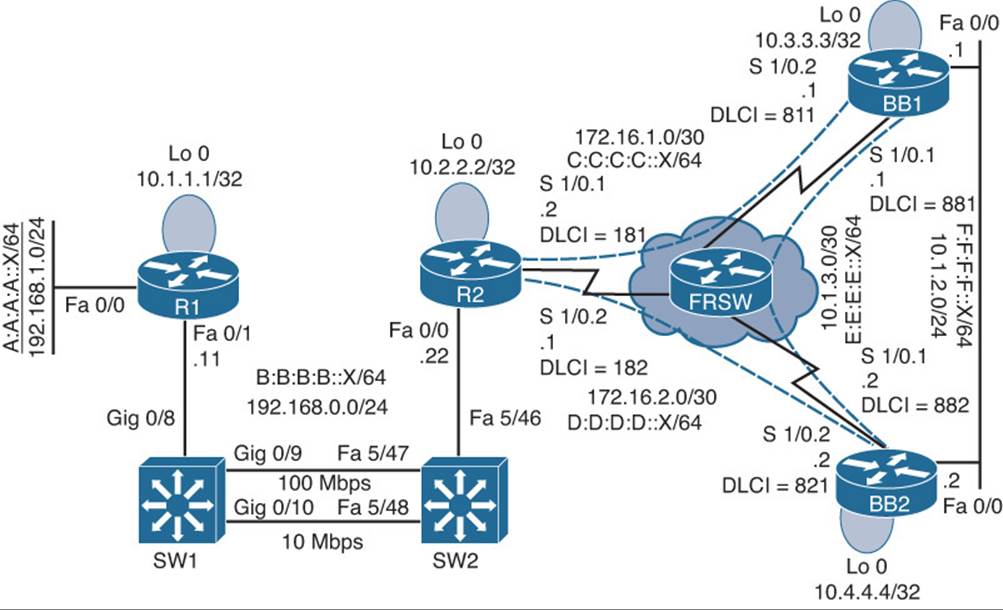
Figure 21-10 Trouble Ticket 10 Topology
The show ipv6 route command was issued on router R2 to confirm that the IPv6 routing table included only a single path to reach the default network of ::/0. Example 21-95 provides the output from this command, which also confirms the presence of the routes E:E:E:E::/64 and F:F:F:F::/64 in the IPv6 routing table.
Example 21-95 Confirmation of Troubleshooting Issues on Router R2
R2#show ipv6 route
IPv6 Routing Table - 12 entries
Codes: C - Connected, L - Local, S - Static, R - RIP, B - BGP
U - Per-user Static route
I1 - ISIS L1, I2 - ISIS L2, IA - ISIS interarea, IS - ISIS summary
O - OSPF intra, OI - OSPF inter, OE1 - OSPF ext 1, OE2 - OSPF ext 2
ON1 - OSPF NSSA ext 1, ON2 - OSPF NSSA ext 2
R ::/0 [120/2]
via FE80::C200:EFF:FE64:0, Serial1/0.2
R A:A:A:A::/64 [120/2]
via FE80::209:B7FF:FEFA:D1E1, FastEthernet0/0
C B:B:B:B::/64 [0/0]
via ::, FastEthernet0/0
L B:B:B:B::22/128 [0/0]
via ::, FastEthernet0/0
C C:C:C:C::/64 [0/0]
via ::, Serial1/0.1
L C:C:C:C::2/128 [0/0]
via ::, Serial1/0.1
C D:D:D:D::/64 [0/0]
via ::, Serial1/0.2
L D:D:D:D::1/128 [0/0]
via ::, Serial1/0.2
R E:E:E:E::/64 [120/2]
via FE80::C200:EFF:FE64:0, Serial1/0.2
R F:F:F:F::/64 [120/2]
via FE80::C200:EFF:FE64:0, Serial1/0.2
L FE80::/10 [0/0]
via ::, Null0
L FF00::/8 [0/0]
via ::, Null0
The show ipv6 rip database command, as shown in Example 21-96, proves that router R2 received two default route advertisements; however, only one of those route advertisements was injected into the IPv6 routing table.
Example 21-96 RIP Database on Router R2
R2#show ipv6 rip database
RIP process "PROCESS1", local RIB
A:A:A:A::/64, metric 2, installed
FastEthernet0/0/FE80::209:B7FF:FEFA:D1E1, expires in 174 secs
B:B:B:B::/64, metric 2
FastEthernet0/0/FE80::209:B7FF:FEFA:D1E1, expires in 174 secs
D:D:D:D::/64, metric 2
Serial1/0.2/FE80::C200:EFF:FE64:0, expires in 160 secs
E:E:E:E::/64, metric 2, installed
Serial1/0.2/FE80::C200:EFF:FE64:0, expires in 160 secs
F:F:F:F::/64, metric 2, installed
Serial1/0.2/FE80::C200:EFF:FE64:0, expires in 160 secs
::/0, metric 2, installed
Serial1/0.2/FE80::C200:EFF:FE64:0, expires in 160 secs
Serial1/0.1/FE80::C202:EFF:FEBC:0, expires in 170 secs
Example 21-97 shows the running configuration on router R2.
Example 21-97 Running Configuration on Router R2
R2#show run
...OUTPUT OMITTED...
hostname R2
!
ipv6 unicast-routing
ipv6 cef
!
interface Loopback0
ip address 10.2.2.2 255.255.255.255
!
interface FastEthernet0/0
ip address 192.168.0.22 255.255.255.0
ipv6 address B:B:B:B::22/64
ipv6 rip PROCESS1 enable
!
interface Serial1/0
no ip address
encapsulation frame-relay
serial restart-delay 0
!
interface Serial1/0.1 point-to-point
ip address 172.16.1.2 255.255.255.252
ipv6 address C:C:C:C::2/64
ipv6 rip PROCESS1 enable
frame-relay interface-dlci 181
!
interface Serial1/0.2 point-to-point
ip address 172.16.2.1 255.255.255.252
ipv6 address D:D:D:D::1/64
ipv6 rip PROCESS1 enable
frame-relay interface-dlci 182
!
ipv6 router rip PROCESS1
maximum-paths 1
!
...OUTPUT OMITTED...
Issue 1: Router R2 Not Load Balancing Between Routers BB1 and BB2
The first issue you investigate is router R2 not load balancing between the HQ routers (that is, routers BB1 and BB2). Based on the show command output presented in Examples 21-95, 21-96, and 21-97, hypothesize why router R2’s IPv6 routing table contains only a single entry for a default network (rather than having two entries, one for BB1 and one for BB2). On a separate sheet of paper, write out your proposed configuration change to resolve this issue.
Issue 1: Suggested Solution
A review of router R2’s running configuration reveals the maximum-paths 1 command in router configuration mode for the RIPng routing process. This command prevents two default route paths from appearing in router R2’s IPv6 routing table. Example 21-98 shows how this command is removed from router R2’s configuration to restore load balancing.
Example 21-98 Restoring Load Balancing on Router R2
R2#conf term
Enter configuration commands, one per line. End with CNTL/Z.
R2(config)#ipv6 router rip PROCESS1
R2(config-rtr)#no maximum-paths 1
Issue 2: Backbone Routes Not Being Suppressed
The second issue you investigate is about the specific routes (that is, E:E:E:E::/64 and F:F:F:F::/64) being advertized to Branch site A (R1 and R2). The goal is to only advertise default route information into Branch site A.
The debug ipv6 rip command was issued on router R2 to see if router BB2 was sending both default route information and specific route information. The output from this command, as presented in Example 21-99, confirms that router BB2 is not suppressing specific route information.
Example 21-99 Debugging RIPng Traffic on Router R2
R2#debug ipv6 rip
...OUTPUT OMITTED...
*Mar 1 00:33:30.747: RIPng: response received from FE80::C200:EFF:FE64:0 on Serial1/0.2 for PROCESS1
*Mar 1 00:33:30.751: src=FE80::C200:EFF:FE64:0 (Serial1/0.2)
*Mar 1 00:33:30.751: dst=FF02::9
*Mar 1 00:33:30.755: sport=521, dport=521, length=92
*Mar 1 00:33:30.755: command=2, version=1, mbz=0, #rte=4
*Mar 1 00:33:30.755: tag=0, metric=1, prefix=F:F:F:F::/64
*Mar 1 00:33:30.755: tag=0, metric=1, prefix=E:E:E:E::/64
*Mar 1 00:33:30.755: tag=0, metric=1, prefix=D:D:D:D::/64
*Mar 1 00:33:30.755: tag=0, metric=1, prefix=::/0
...OUTPUT OMITTED...
Examples 21-100 and 21-101 show the RIP next generation (RIPng) configuration of the Serial 1/0.2 subinterface on routers BB1 and BB2. The Serial 1/0.2 subinterface on each router is the subinterface connecting to router R2.
Example 21-100 Viewing the RIPng Configuration on Router BB1’s Serial 1/0.2 Subinterface
BB1#show run | begin Serial1/0.2
interface Serial1/0.2 point-to-point
ip address 172.16.1.1 255.255.255.252
ipv6 address C:C:C:C::1/64
ipv6 rip PROCESS1 enable
ipv6 rip PROCESS1 default-information only
frame-relay interface-dlci 811
Example 21-101 Viewing the RIPng Configuration on Router BB2’s Serial 1/0.2 Subinterface
BB2#show run | begin Serial1/0.2
interface Serial1/0.2 point-to-point
ip address 172.16.2.2 255.255.255.252
ipv6 address D:D:D:D::2/64
ipv6 rip PROCESS1 enable
ipv6 rip PROCESS1 default-information originate
frame-relay interface-dlci 821
Based on the debug and show commands output presented in Examples 21-99, 21-100, and 21-101, hypothesize why router R2 is receiving specific route information for networks E:E:E:E::/64 and F:F:F:F::/64. On a separate sheet of paper, write out your proposed configuration change to resolve this issue.
Issue 2: Suggested Solution
An inspection of router BB2’s running configuration reveals the ipv6 rip PROCESS1 default-information originate command under subinterface configuration mode for Serial 1/0.2. The originate keyword in this command sources a default router advertisement, but it does not suppress the sending of more specific routes. Example 21-102 shows how this configuration was changed to use the only parameter. The only parameter causes the interface to only originate default route information, while suppressing more specific routes.
Example 21-102 Suppressing Specific Route Information on Router BB2’s Serial Interface
BB2#conf term
Enter configuration commands, one per line. End with CNTL/Z.
BB2(config)#int s1/0.2
BB2(config-subif)#ipv6 rip PROCESS1 default-information only
After giving the E:E:E:E::/64 and F:F:F:F::/64 routes sufficient time to time out of router R2’s IPv6 routing table, the show ipv6 route was once again issued. The output, as shown in Example 21-103, confirms that the issues reported in the trouble ticket are resolved. Specifically, router R2 sees two paths across which it can load balance to reach a default route. Also, specific routes (that is, E:E:E:E::/64 and F:F:F:F::/64) do not appear in router R2’s IPv6 routing table.
Example 21-103 Router R2’s IPv6 Routing Table After Troubleshooting
R2#show ipv6 route
IPv6 Routing Table - 10 entries
Codes: C - Connected, L - Local, S - Static, R - RIP, B - BGP
U - Per-user Static route
I1 - ISIS L1, I2 - ISIS L2, IA - ISIS interarea, IS - ISIS summary
O - OSPF intra, OI - OSPF inter, OE1 - OSPF ext 1, OE2 - OSPF ext 2
ON1 - OSPF NSSA ext 1, ON2 - OSPF NSSA ext 2
R ::/0 [120/2]
via FE80::C200:EFF:FE64:0, Serial1/0.2
via FE80::C202:EFF:FEBC:0, Serial1/0.1
R A:A:A:A::/64 [120/2]
via FE80::209:B7FF:FEFA:D1E1, FastEthernet0/0
C B:B:B:B::/64 [0/0]
via ::, FastEthernet0/0
L B:B:B:B::22/128 [0/0]
via ::, FastEthernet0/0
C C:C:C:C::/64 [0/0]
via ::, Serial1/0.1
L C:C:C:C::2/128 [0/0]
via ::, Serial1/0.1
C D:D:D:D::/64 [0/0]
via ::, Serial1/0.2
L D:D:D:D::1/128 [0/0]
via ::, Serial1/0.2
L FE80::/10 [0/0]
via ::, Null0
L FF00::/8 [0/0]
via ::, Null0
All materials on the site are licensed Creative Commons Attribution-Sharealike 3.0 Unported CC BY-SA 3.0 & GNU Free Documentation License (GFDL)
If you are the copyright holder of any material contained on our site and intend to remove it, please contact our site administrator for approval.
© 2016-2026 All site design rights belong to S.Y.A.