CCNP Routing and Switching TSHOOT 300-135 Official Cert Guide (2015)
Part II. Troubleshooting Cisco Catalyst Switch Features
Chapter 4. Troubleshooting Layer 2 Trunks, VTP, and VLANs
This chapter covers the following topics:
![]() Frame-Forwarding Process: This section reviews the Layer 2 frame-forwarding process. To successfully troubleshoot Layer 2 issues, you need to have a complete understanding of this process.
Frame-Forwarding Process: This section reviews the Layer 2 frame-forwarding process. To successfully troubleshoot Layer 2 issues, you need to have a complete understanding of this process.
![]() Troubleshooting Trunks: This section focuses on how to troubleshoot Layer 2 trunking issues.
Troubleshooting Trunks: This section focuses on how to troubleshoot Layer 2 trunking issues.
![]() Troubleshooting VTP: This section focuses on how to troubleshoot issues relating to VLAN Trunking Protocol.
Troubleshooting VTP: This section focuses on how to troubleshoot issues relating to VLAN Trunking Protocol.
![]() Troubleshooting VLANs: This section identifies how to troubleshoot general issues relating to VLANs and end-user port assignments.
Troubleshooting VLANs: This section identifies how to troubleshoot general issues relating to VLANs and end-user port assignments.
![]() The MAC address table: This section reviews how to use the MAC address table during your troubleshooting process.
The MAC address table: This section reviews how to use the MAC address table during your troubleshooting process.
![]() Layer 2 Trouble Tickets: This section provides trouble tickets that demonstrate how you can use a structured troubleshooting process to solve a reported problem.
Layer 2 Trouble Tickets: This section provides trouble tickets that demonstrate how you can use a structured troubleshooting process to solve a reported problem.
Most enterprise LANs rely on some flavor of Ethernet technology (for example, Ethernet, Fast Ethernet, or Gigabit Ethernet). In addition, your overall campus design will determine whether you need to worry about Layer 2 technologies such as trunks, Virtual Trunking Protocol (VTP), Dynamic Trunking Protocol (DTP), and virtual local-area networks (VLANs). If your campus design has any Layer 2 links from the distribution layer to the access layer, you need to have the skills necessary to troubleshoot these Layer 2 technologies.
However, before you master the skills for troubleshooting these Layer 2 technologies, you need to have an understanding of Ethernet switch operations at Layer 2. This chapter sets the stage by reviewing basic Layer 2 switch operations, which will factor into discussions in future chapters. It then moves on to troubleshooting trunks, VTP, and VLANs.
“Do I Know This Already?” Quiz
The “Do I Know This Already?” quiz allows you to assess whether you should read this entire chapter thoroughly or jump to the “Exam Preparation Tasks” section. If you are in doubt about your answers to these questions or your own assessment of your knowledge of the topics, read the entire chapter. Table 4-1 lists the major headings in this chapter and their corresponding “Do I Know This Already?” quiz questions. You can find the answers in Appendix A, “Answers to the ‘Do I Know This Already?’ Quizzes.”
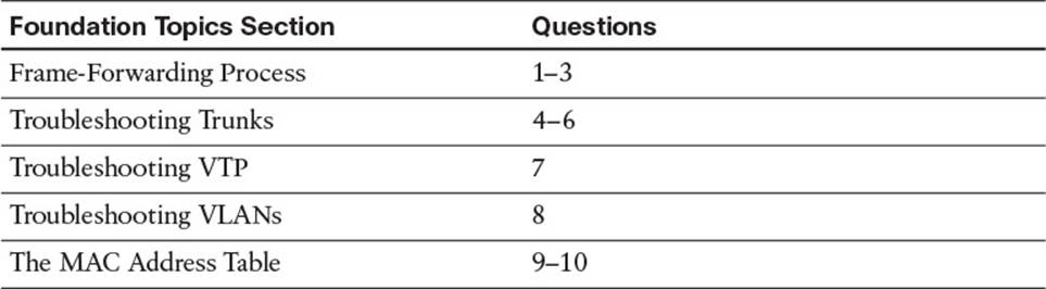
Table 4-1 “Do I Know This Already?” Section-to-Question Mapping
Caution
The goal of self-assessment is to gauge your mastery of the topics in this chapter. If you do not know the answer to a question or are only partially sure of the answer, you should mark that question as wrong for purposes of the self-assessment. Giving yourself credit for an answer that you correctly guess skews your self-assessment results and might provide you with a false sense of security.
1. Which header information is used by switches to learn which MAC address is reachable out a specific interface?
a. Source IP address
b. Destination IP address
c. Source MAC address
d. Destination MAC address
2. Which header information is used by switches to forward frames?
a. Source IP address
b. Destination IP address
c. Source MAC address
d. Destination MAC address
3. What does a switch do with an unknown unicast frame?
a. Drop it
b. Forward it out the port it is associated with
c. Use ARP to determine the MAC address of the IP address in the packet
d. Flood it out all ports except the port it was received on
4. Which two are examples of issues that could prevent a trunk from forming?
a. Encapsulation mismatch
b. Incompatible trunking modes
c. Password mismatch
d. Missing VLAN
5. Which two of the trunk mode examples will successfully form a trunk?
a. Access – Dynamic desirable
b. Dynamic Auto – Dynamic auto
c. Trunk – Dynamic auto
d. Trunk – Trunk nonegotiate
6. Which command enables you to verify the administrative mode and operational mode of an interface?
a. show interfaces trunk
b. show run interface interface_type interface_number
c. show interfaces interface_type interface_number switchport
d. show interfaces
7. Which command enables you to verify VTP configurations?
a. show run
b. show interfaces
c. show vtp status
d. show vtp configurations
8. Which two commands enable you to verify which VLAN a port is assigned to?
a. show vlan brief
b. show interfaces interface_type interface_number switchport
c. show interfaces trunk
d. show mac address-table dynamic
9. Which command enables you to verify which port a MAC address is being learned on?
a. show vlan brief
b. show interfaces interface_type interface_number switchport
c. show interfaces trunk
d. show mac address-table dynamic
10. What can we confirm when examining the MAC address table of a switch? (Choose two answers.)
a. The port a MAC address was learned on
b. The VLAN the MAC address is associated with
c. The administrative and operational mode of an interface
d. The number of devices physically connected to an interface
Foundation Topics
Frame-Forwarding Process
To successfully troubleshoot Layer 2 forwarding issues, you need a solid understanding of how a switch operates. You would have learned this back in CCNA Routing and Switching. However, we spend time here reviewing switch operations because our troubleshooting efforts will be based on this knowledge. This section reviews how a switch populates its MAC address table and how it decides what to do with a frame based on the information in the MAC address table.

Unlike Ethernet hubs, which take bits in one port and send those same bits out all other ports, Ethernet switches learn about the devices connected to their ports. Therefore, when an Ethernet switch sees a frame destined for a particular MAC address, the switch can consult its MAC address table to determine which port to forward the newly arrived frame out. This behavior results in more-efficient bandwidth utilization and improved security on a LAN. In addition, it eliminates the concern of collisions. Specifically, in a hub environment, if two endpoints each transmitted a data frame at the same time, those two frames would collide, resulting in both frames being corrupted because all ports on a hub are in a common collision domain. This collision would require each endpoint to retransmit its data frame. This is not a concern with switches because every port on an Ethernet switch is in its own collision domain.
Ethernet switches can dynamically learn the MAC addresses attached to various switchports by looking at the source MAC address on frames coming into a port. For example, if switchport Gigabit Ethernet 1/1 received a frame with a source MAC address of DDDD.DDDD.DDDD, the switch could conclude that MAC address DDDD.DDDD.DDDD resided off of port Gigabit Ethernet 1/1. As a result, it places an entry in the MAC address table indicating so. In the future, if the switch received a frame destined for a MAC address of DDDD.DDDD.DDDD, the switch would only send that frame out of port Gigabit Ethernet 1/1 because of the entry in the MAC address table.
Initially, however, a switch is unaware of what MAC addresses reside off of which ports (unless MAC addresses have been statically configured). Therefore, when a switch receives a frame destined for a MAC address not yet present in the switch’s MAC address table, the switch floods that frame out of all the switchports in the same VLAN, other than the port on which the frame was received. Similarly, broadcast frames (that is, frames with a destination MAC address of FFFF.FFFF.FFFF) are always flooded out all switchports in the same VLAN except the port on which the frame was received. The reason broadcast frames are always flooded is that no endpoint will have a MAC address of FFFF.FFFF.FFFF, meaning that the FFFF.FFFF.FFFF MAC address will never be learned dynamically in the MAC address table of a switch. In addition, if you look at the output of the MAC address table, you will notice that the all F’s MAC address is statically bound to the CPU, ensuring that it can never be learned dynamically, as shown in Example 4-1.
Example 4-1 show mac address-table Command Output
SW1#show mac address-table
Mac Address Table
-------------------------------------------
Vlan Mac Address Type Ports
---- ----------- -------- -----
All 0100.0ccc.cccc STATIC CPU
All 0100.0ccc.cccd STATIC CPU
All 0180.c200.0000 STATIC CPU
All 0180.c200.0001 STATIC CPU
All 0180.c200.0002 STATIC CPU
All 0180.c200.0003 STATIC CPU
All 0180.c200.0004 STATIC CPU
All 0180.c200.0005 STATIC CPU
All 0180.c200.0006 STATIC CPU
All 0180.c200.0007 STATIC CPU
All 0180.c200.0008 STATIC CPU
All 0180.c200.0009 STATIC CPU
All 0180.c200.000a STATIC CPU
All 0180.c200.000b STATIC CPU
All 0180.c200.000c STATIC CPU
All 0180.c200.000d STATIC CPU
All 0180.c200.000e STATIC CPU
All 0180.c200.000f STATIC CPU
All 0180.c200.0010 STATIC CPU
All ffff.ffff.ffff STATIC CPU
10 0050.b60c.f258 DYNAMIC Gi0/1
10 0800.2757.1b86 DYNAMIC Gi0/1
10 0800.275d.06d6 DYNAMIC Fa0/1
10 0800.27a2.ce47 DYNAMIC Fa0/2
10 2893.fe3a.e301 DYNAMIC Gi0/1
...output omitted...
To illustrate how a switch’s MAC address table becomes populated, consider an endpoint named PC1 that wants to form a Telnet connection with a server, as shown in Figure 4-1. Also, assume that PC1 and its server reside on the same subnet (that is, no routing is required to get traffic between PC1 and its server) and are therefore in the same VLAN, in this case VLAN 100. Before PC1 can send a Telnet segment to its server, PC1 needs to know the IP address (that is, the Layer 3 address) and the MAC address (that is, the Layer 2 address) of the server. The IP address of the server is typically known or is resolved via a Domain Name System (DNS) lookup. In this example, assume that the server’s IP address is known. To properly communicate over Ethernet, PC1 needs to know the server’s Layer 2 MAC address. If PC1 does not already have the server’s MAC address in its Address Resolution Protocol (ARP) cache, PC1 can send an ARP request to learn the server’s MAC address.
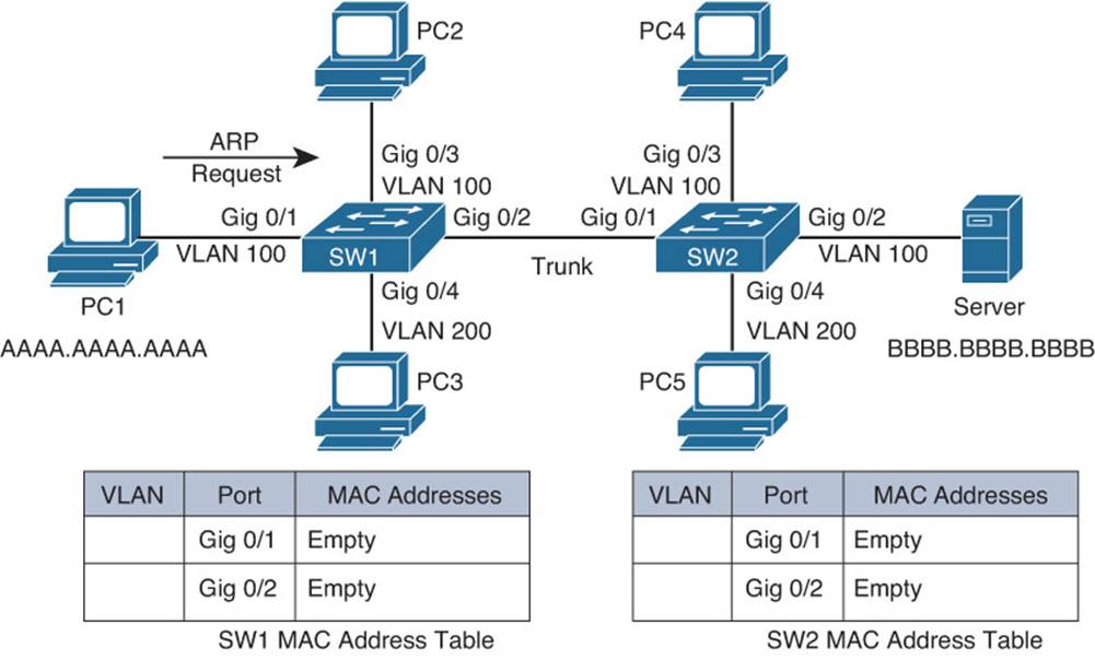
Figure 4-1 Endpoint Sending an ARP Request
When switch SW1 sees PC1’s ARP request enter port Gig0/1, the PC1 MAC address of AAAA.AAAA.AAAA is added to the MAC address table of switch SW1 and associated with interface Gig0/1. Because Gig0/1 is a member of VLAN 100, the MAC is also associated with VLAN 100. Because the ARP request is a broadcast, its destination MAC address is FFFF.FFFF.FFFF (all F’s). As discussed earlier, frames with a destination of all F’s will be copied and flooded out all switchports except the port on which the frame was received. However, notice that port Gig0/1 on switch SW1 belongs to VLAN 100, whereas port Gig0/4 belongs to VLAN 200. This is important because frames are constrained to the VLAN from which they originated unless routed by a Layer 3 device. Therefore, the broadcast frame in this case is not flooded out Gig0/4 because Gig0/4 is a member of a different VLAN. Port Gig0/2, however, is a trunk port, and a trunk can carry traffic for multiple VLANs. Therefore, the ARP request is flooded out of port Gig0/2 and Gig0/3, as illustrated in Figure 4-2. Because the ARP request is for the MAC of the server, PC2 will ignore the ARP request.
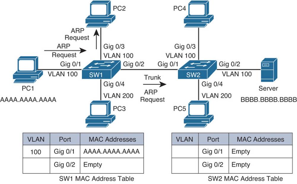
Figure 4-2 Switch SW1 Flooding the ARP Request
When switch SW2 receives the ARP request inbound on its Gig0/1 trunk port, the source MAC address of AAAA.AAAA.AAAA is added to switch SW2’s MAC address table, associated with Gig0/1 and VLAN 100. Also, similar to the behavior of switch SW1, switch SW2 floods the broadcast frame out of port Gig0/3 (a member of VLAN 100) and out of port Gig0/2 (also a member of VLAN 100), as depicted in Figure 4-3.
Figure 4-3 Switch SW2 Flooding the ARP Request
The server receives the ARP request and responds with an ARP reply, as shown in Figure 4-4. In addition, the server updates its ARP cache with a mapping of the IP and MAC address of PC1. Unlike the ARP request, the ARP reply frame is not a broadcast frame; it is a unicast frame. The ARP reply in this case has a destination MAC address of AAAA.AAAA.AAAA and a source MAC address of BBBB.BBBB.BBBB.

Figure 4-4 ARP Reply Sent from the Server
Upon receiving the ARP reply from the server, switch SW2 adds the server’s MAC address of BBBB.BBBB.BBBB to its MAC address table, as shown in Figure 4-5. Also, the ARP reply is sent out only port Gig0/1 because switch SW2 knows that the destination MAC address of AAAA.AAAA.AAAA is reachable out port Gig0/1.
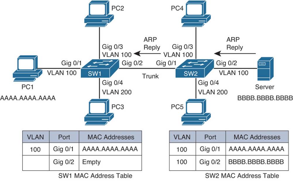
Figure 4-5 Switch SW2 Forwarding the ARP Reply
When receiving the ARP reply in its Gig0/2 port, switch SW1 adds the server’s MAC address of BBBB.BBBB.BBBB to its MAC address table. Also, like switch SW2, switch SW1 now has an entry in its MAC address table for the frame’s destination MAC address of AAAA.AAAA.AAAA. Therefore, switch SW1 forwards the ARP reply out port Gig0/1 to the endpoint of PC1, as illustrated in Figure 4-6.

Figure 4-6 Switch SW1 Forwarding the ARP Reply
After receiving the server’s ARP reply, PC1 now knows the MAC address of the server. Therefore, PC1 can send a properly constructed Telnet segment destined for the server, as depicted in Figure 4-7. The source MAC of the Layer 2 frame will be AAAA.AAAA.AAAA, and the destination MAC will be BBBB.BBBB.BBBB.
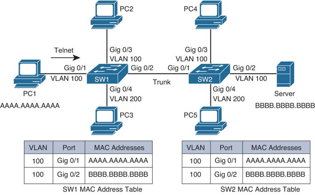
Figure 4-7 PC1 Sending a Telnet Segment
Switch SW1 has the server’s MAC address of BBBB.BBBB.BBBB in its MAC address table. Therefore, when switch SW1 receives the frame from PC1, that frame is forwarded out of the Gig0/2 port of switch SW1, as shown in Figure 4-8.
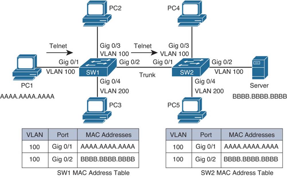
Figure 4-8 Switch SW1 Forwarding the Telnet Segment
Similar to the behavior of switch SW1, switch SW2 forwards the frame out its Gig0/2 port. This forwarding, shown in Figure 4-9, is possible because switch SW2 has an entry for the segment’s destination MAC address of BBBB.BBBB.BBBB in its MAC address table.
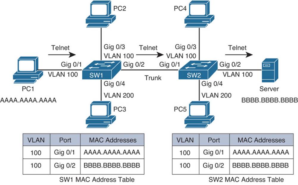
Figure 4-9 Switch SW2 Forwarding the Telnet Segment
Finally, the server responds to PC1, and a bidirectional Telnet session is established between the PC and the server, as illustrated in Figure 4-10. Because PC1 learned the MAC address of the server and the server learned the MAC address of PC1, as a result of PC1’s earlier ARP request, both devices stored the MAC addresses in their local ARP caches; therefore, the transmission of subsequent Telnet segments does not require additional ARP requests. However, if unused for a period of time, entries in a devices ARP cache will time out.

Figure 4-10 Bidirectional Telnet Session Between PC1 and the Server
When troubleshooting an issue involving Layer 2 switch communication, a thorough understanding of the preceding steps can help you identify potential problems quickly and efficiently. Take a moment and review Figure 4-10. Consider where issues might arise in the topology that would prevent PC1 and Server from communicating. The following list outlines a few potential issues that could arise:
![]() PC1 and Server have IP addresses in different subnets because of incorrect address or subnet mask.
PC1 and Server have IP addresses in different subnets because of incorrect address or subnet mask.
![]() Interface Gig0/1 on SW1 or Gig0/2 on SW2 are not members of the correct VLAN.
Interface Gig0/1 on SW1 or Gig0/2 on SW2 are not members of the correct VLAN.
![]() VLAN 100 is missing on SW1 or SW2.
VLAN 100 is missing on SW1 or SW2.
![]() The trunk between SW1 and SW2 is not passing traffic for the necessary VLANs (VLAN 100 in this case).
The trunk between SW1 and SW2 is not passing traffic for the necessary VLANs (VLAN 100 in this case).
![]() The trunk is not formed between SW1 and SW2.
The trunk is not formed between SW1 and SW2.
![]() A VACL is denying PC1 from communicating with Server.
A VACL is denying PC1 from communicating with Server.
![]() Interface Gig0/1 on SW1, Gig0/2 on SW2, or the trunk interfaces are shut down or in the err-disabled state.
Interface Gig0/1 on SW1, Gig0/2 on SW2, or the trunk interfaces are shut down or in the err-disabled state.
Troubleshooting Trunks
Trunks support multiple VLANs on a single physical link. A trunk can be between two switches, a switch and a router, and a switch and a server that is providing services for multiple VLANs. This section focuses on issues that prevent a trunk from being formed or passing traffic for a VLAN. Figure 4-11 serves as the topology for all of the examples.
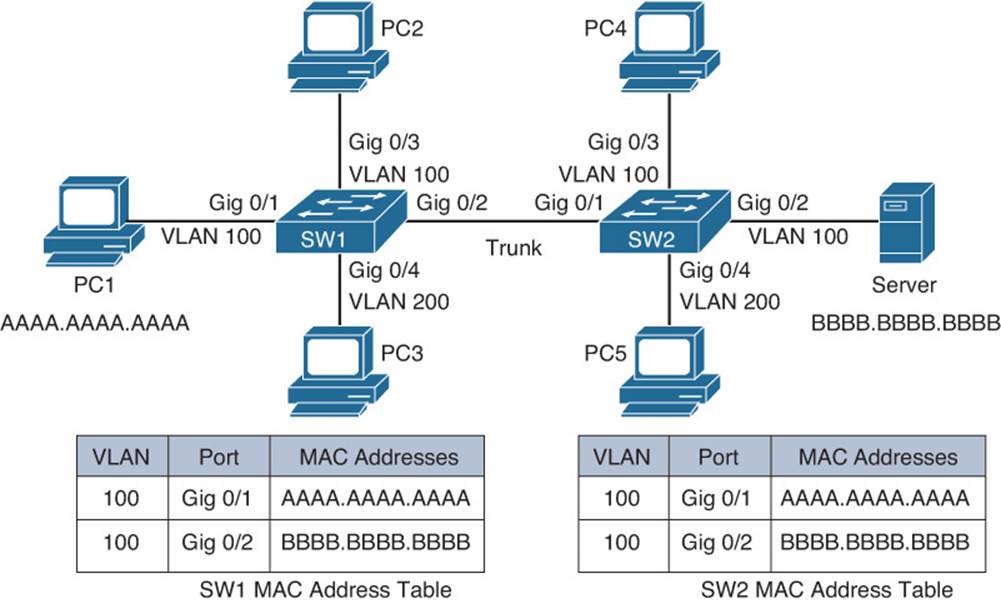
Figure 4-11 Troubleshooting Trunks
Encapsulation Mismatch
Two types of trunking encapsulations are supported by Cisco Catalyst switches: 802.1Q, which is an IEEE standard; and ISL (Inter-Switch Link), which is Cisco proprietary. 802.1Q adds a 4-byte tag to the Ethernet frame, whereas ISL encapsulates the entire Ethernet frame, resulting in an additional 30 bytes. Not all switches support both. For example, a Catalyst 2960 switch supports only 802.1Q, whereas a Catalyst 3560 and a Catalyst 3750-E support both. To form a trunk between two switches, the interfaces that will be forming the trunk must be using the same encapsulation type. By default, Cisco Catalyst switches that support only 802.1Q will use 802.1Q, Catalyst switches that support both 802.1Q and ISL will autonegotiate the encapsulation using DTP. Therefore, if you connect a Catalyst 2960 and a Catalyst 3750-E together, they will use 802.1Q because that is all the Catalyst 2960 can support. However, if you connect two 3750-Es together, they will negotiate the use of ISL because it is Cisco proprietary. If you are required to use 802.1Q trunks in your environment, you must manually change it from ISL to 802.1Q in that situation.
Because autonegotiation of encapsulation works very well, you will usually only have an encapsulation mismatch if someone is manually setting the trunking encapsulation. To verify the encapsulation type used on an interface, issue the show interfaces interface_type interface_numberswitchport command, as shown in Examples 4-2 and 4-3.
Example 4-2 Output of show interfaces switchport Command on SW1 to Verify Encapsulation
SW1#show interfaces gigabitethernet 0/2 switchport
Name: Gi0/2
Switchport: Enabled
Administrative Mode: trunk
Operational Mode: trunk
Administrative Trunking Encapsulation: dot1q
Operational Trunking Encapsulation: dot1q
Negotiation of Trunking: Off
Access Mode VLAN: 1 (default)
Trunking Native Mode VLAN: 99 (NATIVE)
Administrative Native VLAN tagging: enabled
Voice VLAN: none
...output omitted...
Example 4-3 Output of show interface switchport Command on SW2 to Verify Encapsulation
SW2#show interfaces gigabitethernet 0/1 switchport
Name: Gi0/1
Switchport: Enabled
Administrative Mode: trunk
Operational Mode: trunk
Administrative Trunking Encapsulation: isl
Operational Trunking Encapsulation: isl
Negotiation of Trunking: Off
Access Mode VLAN: 1 (default)
Trunking Native Mode VLAN: 99 (NATIVE)
Administrative Native VLAN tagging: enabled
Voice VLAN: none
...output omitted...
From the show interfaces switchport output of Example 4-2 and Example 4-3, you can see that SW1 and SW2 are not using the same trunking encapsulation. SW1 is using 802.1Q, and SW2 is using ISL. Therefore, a trunk will not successfully form in this case.
You can also verify which trunking encapsulation is being used by looking at the output of show interfaces trunk, as shown in Example 4-4 and Example 4-5.
Example 4-4 Output of show interfaces trunk Command on SW1 to Verify Encapsulation
SW1#show interfaces trunk
Port Mode Encapsulation Status Native vlan
Gi0/2 on 802.1q trunking 99
Port Vlans allowed on trunk
Gi0/2 1-4094
Port Vlans allowed and active in management domain
Gi0/2 1,100,200
Port Vlans in spanning tree forwarding state and not pruned
Gi0/2 1,100,200
Example 4-5 Output of show interface trunk Command on SW2 to Verify Encapsulation
SW2#show interfaces trunk
Port Mode Encapsulation Status Native vlan
Gi0/1 on isl trunking 99
Port Vlans allowed on trunk
Gi0/1 1-4094
Port Vlans allowed and active in management domain
Gi0/1 1,100,200
Port Vlans in spanning tree forwarding state and not pruned
Gi0/1 1,100,200
Incompatible Trunking Modes
There are different administrative trunking modes an interface can be configured to use when forming a trunk, as follows:
![]() Access: In this administrative mode, a switchport is manually configured to never become a trunk even if DTP messages are received. This mode is designed for ports that are connecting to, for example, end stations, servers, and printers, where a trunk should never be required because only a single VLAN is needed. This mode can be verified as shown in Example 4-6.
Access: In this administrative mode, a switchport is manually configured to never become a trunk even if DTP messages are received. This mode is designed for ports that are connecting to, for example, end stations, servers, and printers, where a trunk should never be required because only a single VLAN is needed. This mode can be verified as shown in Example 4-6.
![]() Trunk: In this administrative mode, a switchport is manually configured to always be a trunk. This mode can be verified as shown in Example 4-7.
Trunk: In this administrative mode, a switchport is manually configured to always be a trunk. This mode can be verified as shown in Example 4-7.
![]() Dynamic desirable: In this administrative mode, a switchport is aggressively trying to become a trunk by negotiating with the other end of the link to form a trunk using DTP. If the other end of the link agrees then a trunk is formed; if not, it remains an access port that will listen for DTP messages in addition to periodically sending DTP messages as it continues to try and form a trunk. This mode can be verified as shown in Example 4-8.
Dynamic desirable: In this administrative mode, a switchport is aggressively trying to become a trunk by negotiating with the other end of the link to form a trunk using DTP. If the other end of the link agrees then a trunk is formed; if not, it remains an access port that will listen for DTP messages in addition to periodically sending DTP messages as it continues to try and form a trunk. This mode can be verified as shown in Example 4-8.
![]() Dynamic auto: In this administrative mode, a switchport is passively waiting for DTP messages to arrive asking it to form a trunk. If it receives them, it will form a trunk. If it does not receive any, it remains an access port that will listen for DTP messages. This mode can be verified as shown in Example 4-9.
Dynamic auto: In this administrative mode, a switchport is passively waiting for DTP messages to arrive asking it to form a trunk. If it receives them, it will form a trunk. If it does not receive any, it remains an access port that will listen for DTP messages. This mode can be verified as shown in Example 4-9.
Example 4-6 Verifying Trunking Administrative Mode (Access)
SW1#show interfaces gigabitethernet 0/1 switchport
Name: Gi0/1
Switchport: Enabled
Administrative Mode: static access
Operational Mode: static access
Administrative Trunking Encapsulation: negotiate
Operational Trunking Encapsulation: native
Negotiation of Trunking: Off
Access Mode VLAN: 100 (VLAN100)
Trunking Native Mode VLAN: 1 (default)
Administrative Native VLAN tagging: enabled
Voice VLAN: none
...output omitted...
Example 4-7 Verifying Trunking Administrative Mode (Trunk)
SW1#show interfaces gigabitethernet 0/2 switchport
Name: Gi0/2
Switchport: Enabled
Administrative Mode: trunk
Operational Mode: trunk
Administrative Trunking Encapsulation: dot1q
Operational Trunking Encapsulation: dot1q
Negotiation of Trunking: Off
Access Mode VLAN: 1 (default)
Trunking Native Mode VLAN: 99 (NATIVE)
Administrative Native VLAN tagging: enabled
Voice VLAN: none
...output omitted...
Example 4-8 Verifying Trunking Administrative Mode (Dynamic Desirable)
SW1#show interfaces gigabitethernet 0/2 switchport
Name: Gi0/2
Switchport: Enabled
Administrative Mode: dynamic desirable
Operational Mode: trunk
Administrative Trunking Encapsulation: negotiate
Operational Trunking Encapsulation: dot1q
Negotiation of Trunking: On
Access Mode VLAN: 1 (default)
Trunking Native Mode VLAN: 99 (NATIVE)
Administrative Native VLAN tagging: enabled
Voice VLAN: none
...output omitted...
Example 4-9 Verifying Trunking Administrative Mode (Dynamic Auto)
SW1#show interfaces gigabitethernet 0/2 switchport
Name: Gi0/2
Switchport: Enabled
Administrative Mode: dynamic auto
Operational Mode: trunk
Administrative Trunking Encapsulation: negotiate
Operational Trunking Encapsulation: dot1q
Negotiation of Trunking: On
Access Mode VLAN: 1 (default)
Trunking Native Mode VLAN: 99 (NATIVE)
Administrative Native VLAN tagging: enabled
Voice VLAN: none
...output omitted...
The default administrative mode varies by Catalyst switch model. To verify the default administrative mode on your model, issue the show interfaces interface_type interface_number switchport command for an interface that is still using factory default settings. Example 4-10 shows that interface Gigabit Ethernet 0/1 is using factory default settings, because no other configurations have been applied to the interface, as shown in the show run interface gigabitethernet 0/1 output. The output of show interfaces gigabitethernet 0/1 switchport | include Administrative Modeindicates that the trunking administrative mode is dynamic auto. Therefore, we can conclude dynamic auto is the default on this switch because there is no command in the running configuration that indicates otherwise.
Example 4-10 Verifying Default Trunking Mode on SW2
SW2#show run interface gigabitethernet 0/1
Building configuration...
Current configuration : 50 bytes
!
interface GigabitEthernet0/1
end
SW2#show interfaces gig 0/1 switchport | include Administrative Mode
Administrative Mode: dynamic auto
Some of these administrative modes are compatible with each other and will form a trunk, whereas others are not, as shown in Table 4-2. While you are looking at Table 4-12, remember that dynamic auto, dynamic desirable, and trunk all use DTP by default.
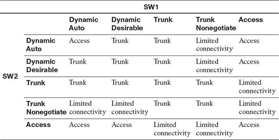
Table 4-2 Comparing Trunking Administrative Modes
As you can see in Table 4-2, if both switchports are configured as dynamic auto, a trunk will not form. The switchports will remain as access ports and pass traffic for the VLAN the port is a member of. To form a trunk with a switchport that is dynamic auto, the other switchport must be using dynamic desirable or trunk (using DTP). Limited connectivity is a result of one side being operationally a trunk and the other side being operationally an access port. Connectivity will occur only if the access port VLAN on one switch happens to be the same as the native VLAN for the 802.1Q trunk on the other switch. If not, connectivity will be broken. The reason is because the access port sends the frames untagged, and once the trunk port receives them at the other end, it considers them as part of the native VLAN because of the lack of a tag. If these VLAN numbers match, the frames can be successfully forwarded without a problem. However, if the native VLAN does not match with the VLAN configured on the access port, the frames when entering or leaving the trunk port on the switch will be part of a different VLAN than the access port and the frames are no longer forwarded correctly, and connectivity is broken. Memorizing Table 4-2 will definitely prove beneficial if you ever have to troubleshoot trunk links that are not forming.
VTP Domain Name Mismatch
We will cover VTP in detail shortly. However, if you are using DTP to dynamically form trunks and the VTP domain name does not match between the two switches, a trunk will not be formed, as shown in Example 4-11.
Example 4-11 VTP Domain Name Mismatch Causes Trunk Not to Form
SW1#
%DTP-5-DOMAINMISMATCH: Unable to perform trunk negotiation on port Gi0/2 because of
VTP domain mismatch.
Native VLAN Mismatch
Trunk issues with the native VLAN only surface when we are using IEEE 802.1Q trunking encapsulation. The concept of a native VLAN does not exist with Cisco ISL trunking encapsulation. The native VLAN by default is VLAN 1 and is used to carry untagged traffic across an 802.1Q trunk. It is imperative that the native VLAN matches on both sides of a trunk link. If it does not, it is possible for traffic to leak from one VLAN to another, resulting in an undesired forwarding behavior and possible errors with Spanning Tree Protocol.
With a native VLAN mismatch, the trunk forms, and syslog messages are generated, as shown in Example 4-12. From the example, you can see that Cisco Discovery Protocol (CDP) is warning you about the native VLAN mismatch; however, if CDP is not enabled, this message would not appear. Example 4-13 displays the output of show interfaces trunk on SW1 and SW2, confirming that we have a native VLAN mismatch.
Example 4-12 Result of a Native VLAN Mismatch on a Trunk
SW1#
%CDP-4-NATIVE_VLAN_MISMATCH: Native VLAN mismatch discovered on GigabitEthernet0/2
(1), with SW2 GigabitEthernet0/1 (99).
SW2#
%CDP-4-NATIVE_VLAN_MISMATCH: Native VLAN mismatch discovered on GigabitEthernet0/1
(99), with SW1 GigabitEthernet0/2 (1).
Example 4-13 Confirming the Native VLAN Mismatch with the show interfaces trunk Command
SW1#show interfaces trunk
Port Mode Encapsulation Status Native vlan
Gi0/2 desirable n-802.1q trunking 1
...output omitted...
SW2#show interfaces trunk
Port Mode Encapsulation Status Native vlan
Gi0/1 desirable n-802.1q trunking 99
...output omitted...
Allowed VLANs
By default, traffic for all VLANs will be forwarded on a trunk. You can modify this behavior by identifying which VLANs are allowed on the trunk. You can accomplish this manually or dynamically. If you are using VTP to propagate VLAN configuration information, you can use the VTP pruning feature, which dynamically determines which VLANs are needed on each of the trunks. You can enable VTP pruning with the vtp pruning global configuration command. Many prefer to control the VLANs allowed on trunks manually with the switchport trunk allowed vlansvlan_id command in interface configuration mode. You can verify which VLANs are allowed on a trunk a few different ways. You can use the show interfaces trunk command, the show interface interface_type interface_number switchport command, or review the interface configuration in the running configuration. Example 4-14 displays the output from these three commands. Focus on the highlighted text because it identifies which VLANs are allowed on the trunk. If traffic is not flowing across a trunk for a specific VLAN, make sure that the VLAN is allowed on the trunk.
Example 4-14 Verifying Allowed VLANs on a Trunk
SW1#show interfaces trunk
Port Mode Encapsulation Status Native vlan
Gi0/2 desirable n-802.1q trunking 99
Port Vlans allowed on trunk
Gi0/2 100,200
Port Vlans allowed and active in management domain
Gi0/2 100,200
Port Vlans in spanning tree forwarding state and not pruned
Gi0/2 100,200
SW1#show interfaces gigabitethernet 0/2 switchport
Name: Gi0/2
Switchport: Enabled
...output omitted...
Trunking VLANs Enabled: 100,200
Pruning VLANs Enabled: 2-1001
Capture Mode Disabled
...output omitted...
SW1#show run interface gigabitethernet 0/2
Building configuration...
Current configuration : 167 bytes
!
interface GigabitEthernet0/2
switchport trunk native vlan 99
switchport trunk allowed vlan 100,200
switchport mode dynamic desirable
end
Troubleshooting VTP
Picture a network with 50 switches and 75 VLANs. You have been tasked with deploying these 75 VLANs to all 50 switches. This is a large task that is definitely prone to human error. VLAN Trunking Protocol (VTP) is designed to ease the deployment of VLAN configuration information between switches across trunk links. This section explains the reasons why VTP might not be sharing VLAN configuration information with other switches in the domain. Figure 4-11 is used as the topology for the examples. SW1 and SW2 need to have the same VLAN database.
Domain Name Mismatch
Switches that will learn VLAN configuration information from each other using VTP need to be in the same VTP domain. The VTP domain is identified by a name known as the VTP domain name, and it can be anything you want it to be. However, it must match on the devices that will be exchanging VLAN configuration information. Suppose, for example, that SW1 in Figure 4-11 is using a VTP domain name of TSHOOT and SW2 is using a VTP domain name of TSHOOT. Obviously, they match. What about SW1 using TSHOOT and SW2 using TSHO0T? It looks like they match, but they do not. The VTP domain name for SW2 has a zero (0) in it instead of the letter O. Compare Examples 4-15 and 4-16, which display the output of show vtp status on SW1 and SW2. Are SW1 and SW2 in the same VTP domain?
Example 4-15 Verifying the VTP Domain Name on SW1
SW1#show vtp status
VTP Version capable : 1 to 3
VTP version running : 3
VTP Domain Name : Tshoot
VTP Pruning Mode : Disabled
VTP Traps Generation : Disabled
Device ID : 001c.57fe.f600
...output omitted...
Example 4-16 Verifying the VTP Domain Name on SW2
SW2#show vtp status
VTP Version capable : 1 to 3
VTP version running : 3
VTP Domain Name : TSHOOT
VTP Pruning Mode : Disabled
VTP Traps Generation : Disabled
Device ID : 2893.fe3b.0100
...output omitted...
Note that case does matter for the VTP domain name. Therefore, SW1 and SW2 are in completely different VTP domains and will not share VLAN configuration information with each other. In addition, as mentioned earlier, if you are using DTP to form a trunk and you have a VTP domain name mismatch, a trunk will not form.
Version Mismatch
There are three versions of VTP: VTPv1, VTPv2, and VTPv3. VTPv1 is the default. If you are running VTPv1, all switches need to be using VTPv1 to successfully exchange VLAN configuration information. If you are running VTPv2 or VTPv3 the switches can be using VTPv2 or VTPv3 because they are compatible. However, to reduce the possibility of issues, it is recommended that you avoid mixing VTP versions. To verify the VTP version in use on a switch, issue the show vtp status command, as shown in Example 4-17. Also notice in the output that SW2 is capable of running all three versions of VTP.
Example 4-17 Verifying the VTP Version on SW2
SW2#show vtp status
VTP Version capable : 1 to 3
VTP version running : 3
VTP Domain Name : TSHOOT
VTP Pruning Mode : Disabled
VTP Traps Generation : Disabled
Device ID : 2893.fe3b.0100
...output omitted...
Mode Mismatch
VTP has four modes of operation: Server, Client, Transparent, and Off. For a switch to use the VLAN configuration information in a VTP message, it must be in Server or Client mode. A switch operating in Transparent mode will ignore the information contained in a VTP message; however, it will still forward on the message to other switches. In Off mode, the switch behaves the same as Transparent mode, except that it will not forward on VTP messages that it receives. Therefore, if you are troubleshooting an issue that involves missing VLANs on a switch and you are using VTP, check whether the switch is in VTP Transparent mode or Off. To verify the VTP mode used on a switch, issue the show vtp status command, as shown in Examples 4-18 and 4-19. In addition, with VTPv3, only the VTP primary server can add or delete VLANs.
Example 4-18 Verifying the VTP Mode on SW1
SW1#show vtp status
VTP Version capable : 1 to 3
VTP version running : 3
VTP Domain Name : SWITCH
VTP Pruning Mode : Disabled
VTP Traps Generation : Disabled
Device ID : 2893.fe3b.0100
Feature VLAN:
--------------
VTP Operating Mode : Server
Number of existing VLANs : 10
Number of existing extended VLANs : 0
Maximum VLANs supported locally : 1005
Configuration Revision : 3
...output omitted...
Example 4-19 Verifying the VTP Mode on SW2
SW2#show vtp status
VTP Version capable : 1 to 3
VTP version running : 3
VTP Domain Name : SWITCH
VTP Pruning Mode : Disabled
VTP Traps Generation : Disabled
Device ID : 001c.57fe.f600
Feature VLAN:
--------------
VTP Operating Mode : Client
Number of existing VLANs : 10
Number of existing extended VLANs : 0
Maximum VLANs supported locally : 255
Configuration Revision : 3
...output omitted...
Password Mismatch
To ensure that a switch only uses VTP configuration information from legitimate sources, it is recommended that a VTP password is set. When a switch receives a VTP message from another switch, it will verify that the attached message digest 5 (MD5) algorithm hash matches its local hash. If it matches, the VTP message is from a legitimate source and is processed. If not, the VTP message is discarded. Remember that the VTP password is case sensitive. Example 4-20 shows how you can verify the password that is configured with the show vtp password command and the hash value that will be used with the show vtp status command.
Example 4-20 Verifying VTP Passwords
SW1#show vtp password
VTP Password: CCNP
SW1#show vtp status
VTP Version capable : 1 to 3
VTP version running : 3
VTP Domain Name : SWITCH
VTP Pruning Mode : Disabled
VTP Traps Generation : Disabled
Device ID : 2893.fe3b.0100
Feature VLAN:
--------------
VTP Operating Mode : Server
Number of existing VLANs : 11
Number of existing extended VLANs : 0
Maximum VLANs supported locally : 1005
Configuration Revision : 2
Primary ID : 2893.fe3a.e300
Primary Description : DSW1
MD5 digest : 0x98 0x29 0xB8 0x5D 0x4D 0x48 0x71 0xE3
0x8A 0x93 0x8E 0x82 0x2B 0xEA 0xA0 0x45
...output omitted...
Higher Revision Number
When a switch in VTP server mode makes a change to the VLAN database, it increments the configuration revision number shown in Example 4-20. Currently it is 2, but if another VLAN were added or a modification were made that affected the VLAN database, VTP would increment the configuration revision number. This number is extremely important because the switch with the higher configuration revision number is considered to have the most up-to-date and valid VLAN database. However, this might not always be the case. For example, suppose that you are preparing for the TSHOOT exam and you are troubleshooting VLANs. You keep adding and deleting VLANs while using VTPv1 to propagate your changes to the other switches in your lab pod. Now you have a really high configuration revision number. The next day a coworker plugs your lab pod into the production network, and your lab VLAN database overwrites the VLAN database of the production network because you were using the same domain name and password on your lab devices and the lab had a higher configuration revision number than the production network. Now you need to rebuild the production VLAN database or restore it from backup, if you have one.
You need to prevent this from ever happening by ensuring no one uses the same VTP domain name or password on other devices and then plugs them into the production network. However, that is hard to control. So, it is better to run all the switches in Transparent mode and only use Server or Client mode when you are building the VLAN database or making significant changes that have to be propagated to all the other switches. This is because Transparent mode switches will not update their VLAN information from VTP messages, protecting you from having your VLAN database overwritten. You may also want to consider having all switches in VTP Transparent mode when they are added to the domain so that their configuration revision number is 0, which it always is for Transparent mode. Your best option is to use VTPv3 because only the VTP primary server will be considered a trusted source of VTP messages within the VTP domain, and any other VTP messages will be ignored, ensuring that your database is not overwritten by a rouge switch.
Troubleshooting VLANs
Our discussions have led us to this important point in this chapter: Being able to identify and solve issues with VLANs. This is an important task for any troubleshooter. Some of these issues could be a result of a trunk or VTP issue, as previously discussed. This section identifies the issues that might arise with VLANs and how you can fix them. The discussion is based on Figure 4-11.
Incorrect IP Addressing
It all starts with the client configuration. If the IP address, subnet mask, or default gateway are not configured correctly, frames will not flow as expected. Example 4-21 displays the output of ipconfig on PC1 and Server. If you look closely, you will notice that Server is not addressed correctly, and therefore not in the same subnet. When PC1 needs to send data to Server, because they are not on the same subnet, PC1 will send the frame to its default gateway so that it can be routed to a different subnet. However, this process will fail at some point because both PC1 and Server cannot be in the same Layer 2 VLAN (as Figure 4-11 shows), within different IP networks. They need to be in the same subnet if they are in the same VLAN so that frames can be sent from PC1 directly to Server based on the Layer 2 MAC addresses.
Example 4-21 Verifying End-User IP Addresses
PC1>ipconfig
Windows IP Configuration
Ethernet adapter Local Area Connection:
Connection-specific DNS Suffix . :
IP Address. . . . . . . . . . . . : 10.1.100.10
Subnet Mask . . . . . . . . . . . : 255.255.255.0
Default Gateway . . . . . . . . . : 10.1.100.1
Server>ipconfig
Windows IP Configuration
Ethernet adapter Local Area Connection:
Connection-specific DNS Suffix . :
IP Address. . . . . . . . . . . . : 10.1.10.11
Subnet Mask . . . . . . . . . . . : 255.255.255.0
Default Gateway . . . . . . . . . : 10.1.10.1
Missing VLAN
For a switch to associate switchports with VLANs or to pass traffic over a trunk for a VLAN, the switch needs to know about the VLAN. The command show vlan brief, as shown in Example 4-22, displays the VLANs that are known by the switch.
Example 4-22 Verifying VLANs on a Switch
SW1#show vlan brief
VLAN Name Status Ports
---- -------------------------------- --------- -------------------------------
1 default active Gi0/5, Gi0/6, Gi0/7, Gi0/8,
Gi0/9, Gi0/10, Gi0/11, Gi0/12,
Gi0/13, Gi0/14, Gi0/15, Gi0/16,
Gi0/17, Gi0/18, Gi0/19, Gi0/20,
Gi0/21, Gi0/22, Gi0/23, Gi0/24,
Te1/0/1, Te1/0/2
99 NATIVE active
100 10.1.100.0/24 active Gi0/1, Gi0/3
200 10.1.200.0/24 active Gi0/4
1002 fddi-default act/unsup
1003 trcrf-default act/unsup
1004 fddinet-default act/unsup
1005 trbrf-default act/unsup
If any VLANs are missing from the output of show vlan brief that should be there, you need to find out why. If VLANs are configured manually in your organization, the answer is one of two reasons: Someone forgot to configure the VLAN on the switch, or someone deleted the VLAN on the switch. If the creation and deletion of VLANs is learned by other switches though VTP, you need to troubleshoot why VTP is not propagating the VLAN information to the other switches. However, it is important to remember that if you are using VTPv1 or 2 and a switch is added to the domain with the correct password, and has a higher revision number, the VLAN database in your VTP domain will be overwritten by this switch. Therefore, if you are missing VLANs, this could be the reason why.
In Example 4-23, which displays the output of show interfaces gigabitethernet 0/1 switchport, focus on the highlighted text. Notice in brackets the name of the VLAN. It is listed as (Inactive). This is a great sign that the interface belongs to a VLAN that does not currently exist on the switch. Note that even though the port is up/up, because the VLAN does not exist, the port will not be forwarding traffic.
Example 4-23 Identifying Missing VLANs on a Switch
SW1#show interfaces gigabitethernet 0/1 switchport
Name: Gi0/1
Switchport: Enabled
Administrative Mode: static access
Operational Mode: static access
Administrative Trunking Encapsulation: negotiate
Operational Trunking Encapsulation: native
Negotiation of Trunking: Off
Access Mode VLAN: 100 (Inactive)
Trunking Native Mode VLAN: 1 (default)
Administrative Native VLAN tagging: enabled
Voice VLAN: none
Incorrect Port Assignment

Once VLANs are created, switchports need to be assigned to VLANs. The assignments should be based on which device is going to be connected to that port (based on IP address, subnet mask, and default gateway). For example, in Figure 4-11, PC1, PC2, PC4, and Server have to be in the same logical subnet because they are all connected to ports in VLAN 100. PC3 and PC5 have to be in the same subnet (but different from the other devices) because they are connected to ports in VLAN 200. If this is not done, the VLAN to switchport assignments would be incorrect, and the switch would not be able to forward the frames successfully between the devices within the same VLAN. Example 4-24 displays the output of show vlan brief, which identifies the VLANs ports are assigned to. By default, all ports are assigned to VLAN 1. Gig0/1 and Gig0/3 have been statically assigned to VLAN 100, and Gig0/4 has been statically assigned to VLAN 200.
Example 4-24 Verifying Switchport Assignment
SW1#show vlan brief
VLAN Name Status Ports
---- -------------------------------- --------- -------------------------------
1 default active Gi0/5, Gi0/6, Gi0/7, Gi0/8,
Gi0/9, Gi0/10, Gi0/11, Gi0/12,
Gi0/13, Gi0/14, Gi0/15, Gi0/16,
Gi0/17, Gi0/18, Gi0/19, Gi0/20,
Gi0/21, Gi0/22, Gi0/23, Gi0/24,
Te1/0/1, Te1/0/2
99 NATIVE active
100 10.1.100.0/24 active Gi0/1, Gi0/3
200 10.1.200.0/24 active Gi0/4
1002 fddi-default act/unsup
1003 trcrf-default act/unsup
1004 fddinet-default act/unsup
1005 trbrf-default act/unsup
It is important to note that ports that belong to VLANs that do not exist will not be displayed in the output of show vlan brief. As Example 4-23 displayed, they will appear as (Inactive) in the output of show interfaces switchport. In addition, trunk ports will not appear in the output of show vlan brief. Notice in Example 4-24 that Gig0/2 is missing because it is a trunk port and does not belong to any single VLAN. It is passing traffic for multiple VLANs.
The MAC Address Table
The MAC address table is the most important table for the switch. The MAC address table is the structure that is used by the switch to make a forwarding decision. If the MAC address table is not being populated the way you expect it, you will need to figure out why. This section covers the MAC address table and its importance, using Figure 4-11 as the reference topology.
Example 4-25 displays the dynamically learned MAC addresses on SW1 with the command show mac address-table dynamic. The structure of the table is important. It lists the VLANs, the dynamically learned MAC addresses, and the ports. This information is extremely valuable. As discussed earlier, it is populated based on the source MAC address of the frame when it arrives on a switchport. Therefore, when SW1 received a frame inbound on Gigabit Ethernet 0/1 from PC1, it learned the MAC from the frame and associated it with the port it arrived on and the VLAN the port is a member of.
Example 4-25 SW1’s MAC Address Table
SW1#show mac address-table dynamic
Mac Address Table
-------------------------------------------
Vlan Mac Address Type Ports
---- ----------- -------- -----
100 aaaa.aaaa.aaaa DYNAMIC Gi0/1
100 bbbb.bbbb.bbbb DYNAMIC Gi0/2
100 cccc.cccc.cccc DYNAMIC Gi0/3
100 dddd.dddd.dddd DYNAMIC Gi0/2
200 3333.3333.3333 DYNAMIC Gi0/4
200 5555.5555.5555 DYNAMIC Gi0/2
Total Mac Addresses for this criterion: 6
Let’s look at an example. What can we conclude by looking at the MAC address table for SW1 displayed in Example 4-26 when comparing it to Figure 4-11?
Example 4-26 Example of SW1’s MAC Address Table
SW1#show mac address-table dynamic
Mac Address Table
-------------------------------------------
Vlan Mac Address Type Ports
---- ----------- -------- -----
100 bbbb.bbbb.bbbb DYNAMIC Gi0/2
100 cccc.cccc.cccc DYNAMIC Gi0/3
100 dddd.dddd.dddd DYNAMIC Gi0/2
200 3333.3333.3333 DYNAMIC Gi0/4
200 5555.5555.5555 DYNAMIC Gi0/2
200 aaaa.aaaa.aaaa DYNAMIC Gi0/1
Total Mac Addresses for this criterion: 6
When comparing Figure 4-11 with Example 4-26, we can conclude that interface Gigabit Ethernet 0/1 is not a member of the correct VLAN. The MAC address table shows the MAC address of PC1 (AAAA.AAAA.AAAA) was learned on the correct interface, but the VLAN number is 200 instead of 100. Reviewing the output of show vlan brief and show interfaces gigabitethernet 0/1 switchport, as demonstrated in Example 4-27, confirms this for us. Our next step is to reassign the port to the correct VLAN.
Example 4-27 Confirming SW1’s VLAN Assignments
SW1#show vlan brief
VLAN Name Status Ports
---- -------------------------------- --------- -------------------------------
1 default active Gi0/5, Gi0/6, Gi0/7, Gi0/8,
Gi0/9, Gi0/10, Gi0/11, Gi0/12,
Gi0/13, Gi0/14, Gi0/15, Gi0/16,
Gi0/17, Gi0/18, Gi0/19, Gi0/20,
Gi0/21, Gi0/22, Gi0/23, Gi0/24,
Te1/0/1, Te1/0/2
99 NATIVE active
100 10.1.100.0/24 active Gi0/3
200 10.1.200.0/24 active Gi0/1, Gi0/4
1002 fddi-default act/unsup
1003 trcrf-default act/unsup
1004 fddinet-default act/unsup
1005 trbrf-default act/unsup
SW1#show interfaces gigabitethernet 0/1 switchport
Name: Gi0/1
Switchport: Enabled
Administrative Mode: static access
Operational Mode: static access
Administrative Trunking Encapsulation: negotiate
Operational Trunking Encapsulation: native
Negotiation of Trunking: Off
Access Mode VLAN: 200 (10.1.200.0/24)
Trunking Native Mode VLAN: 1 (default)
Administrative Native VLAN tagging: enabled
Voice VLAN: none
...output omitted...
While troubleshooting, if you ever need to clear the dynamic entries in the MAC address table immediately so that they can be relearned, giving you the opportunity to confirm the correct associations, issue the clear mac address-table dynamic EXEC command.
Layer 2 Trouble Tickets
This section presents various trouble tickets relating to the topics discussed earlier in the chapter. The purpose of these trouble tickets is to give a process that you can follow when troubleshooting in the real world or in an exam environment. All trouble tickets in this section are based on the topology depicted in Figure 4-12.
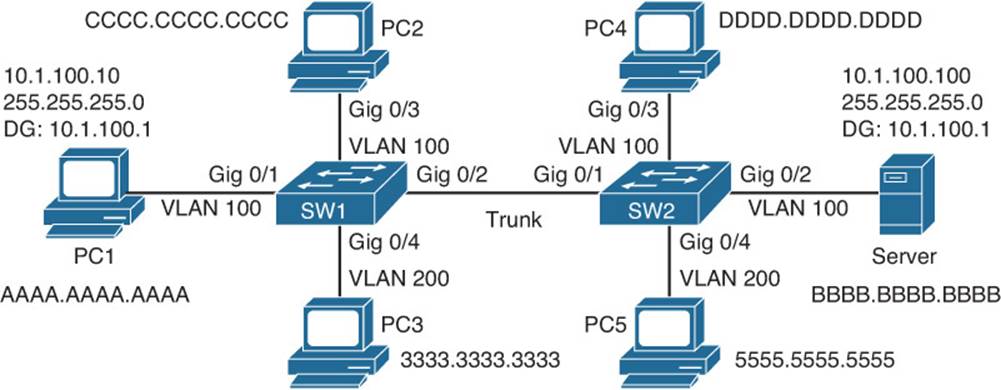
Figure 4-12 Topology for Trouble Tickets
Trouble Ticket 4-1
Problem: A user on PC1 indicates that he is not able to access a document on Server.
This is a typical description within a trouble ticket. Therefore, the first process is to verify the issue. A simple ping from PC1 will help us with this, as shown in Example 4-28.
Example 4-28 Issuing a Ping from PC1
PC1>ping 10.1.100.100
Pinging 10.1.100.100 with 32 bytes of data:
Request timed out.
Request timed out.
Request timed out.
Request timed out.
Ping statistics for 10.1.100.100:
Packets: Sent = 4, Received = 0, Lost = 4 (100% loss),
The output of Example 4-28 indicates that the ping failed. What did we learn from this ping? We learned that we have no connectivity from Layer 1 to Layer 3 of the OSI model. Therefore, we can focus our troubleshooting efforts at these layers. However, let’s verify whether others are having the same issue. A ping from PC2 is successful, as shown in Example 4-29. Therefore, it is not a problem with the server or the path from PC2 to the server, which is similar to PC1.
Example 4-29 Issuing a Ping from PC2
PC2>ping 10.1.100.100
Pinging 10.1.100.100 with 32 bytes of data:
Reply from 10.1.100.100: bytes=32 time 1ms TTL=128
Reply from 10.1.100.100: bytes=32 time 1ms TTL=128
Reply from 10.1.100.100: bytes=32 time 1ms TTL=128
Reply from 10.1.100.100: bytes=32 time 1ms TTL=128
Ping statistics for 10.1.100.100:
Packets: Sent = 4, Received = 4, Lost = 0 (0% loss),
Approximate round trip times in milli-seconds:
Minimum = 0ms, Maximum = 0ms, Average = 0ms
Let’s start by checking the IP address of PC1. Using the ipconfig command, as shown in Example 4-30, indicates that the IP address, subnet mask, and default gateway are 10.1.100.10, 255.255.255.0, and 10.1.100.1. According to Figure 4-11, these are correct.
Example 4-30 Verifying PC1’s Layer 3 Settings
PC1>ipconfig
Windows IP Configuration
Ethernet adapter Local Area Connection:
Connection-specific DNS Suffix . :
IP Address. . . . . . . . . . . . : 10.1.100.10
Subnet Mask . . . . . . . . . . . : 255.255.255.0
Default Gateway . . . . . . . . . : 10.1.100.1
The next step is to check the MAC address table on SW1 using the command show mac address-table dynamic. Example 4-31 shows that the MAC address of PC1 was learned on Gigabit Ethernet 0/1, which is correct, but it is associated with VLAN 1 instead of VLAN 100. It appears we have found the problem. However, let’s confirm this further with the show vlan brief command, as shown in Example 4-32.
Example 4-31 Verifying PC1 in the MAC Address Table on SW1
SW1#show mac address-table dynamic
Mac Address Table
-------------------------------------------
Vlan Mac Address Type Ports
---- ----------- -------- -----
1 aaaa.aaaa.aaaa DYNAMIC Gi0/1
100 bbbb.bbbb.bbbb DYNAMIC Gi0/2
100 cccc.cccc.cccc DYNAMIC Gi0/3
100 dddd.dddd.dddd DYNAMIC Gi0/2
200 3333.3333.3333 DYNAMIC Gi0/4
200 5555.5555.5555 DYNAMIC Gi0/2
Total Mac Addresses for this criterion: 6
Example 4-32 Verifying VLAN Port Assignments with the show vlan brief Command
SW1#show vlan brief
VLAN Name Status Ports
---- -------------------------------- --------- -------------------------------
1 default active Gi0/1, Gi0/5, Gi0/6, Gi0/7,
Gi0/8, Gi0/9, Gi0/10, Gi0/11,
Gi0/12, Gi0/13, Gi0/14, Gi0/15,
Gi0/16, Gi0/17, Gi0/18, Gi0/19,
Gi0/20, Gi0/21, Gi0/22, Gi0/23,
Gi0/24, Te1/0/1, Te1/0/2
99 NATIVE active
100 10.1.100.0/24 active Gi0/3
200 10.1.200.0/24 active Gi0/4
1002 fddi-default act/unsup
1003 trcrf-default act/unsup
1004 fddinet-default act/unsup
1005 trbrf-default act/unsup
To solve the problem, we change the switchport VLAN assignment with the switchport access vlan 100 interface command and verify that the problem is solved by pinging from PC1 again. Example 4-33 confirms that the problem is solved.
Example 4-33 Confirming That the Problem Is Solved with a Successful Ping
PC1>ping 10.1.100.100
Pinging 10.1.100.100 with 32 bytes of data:
Reply from 10.1.100.100: bytes=32 time 1ms TTL=128
Reply from 10.1.100.100: bytes=32 time 1ms TTL=128
Reply from 10.1.100.100: bytes=32 time 1ms TTL=128
Reply from 10.1.100.100: bytes=32 time 1ms TTL=128
Ping statistics for 10.1.100.100:
Packets: Sent = 4, Received = 4, Lost = 0 (0% loss),
Approximate round trip times in milli-seconds:
Minimum = 0ms, Maximum = 0ms, Average = 0ms
Trouble Ticket 4-2
Problem: A user on PC2 indicates that she is not able to access a document on Server.
As before, the first process is to verify the issue. A simple ping from PC2 will help us with this, as shown in Example 4-34.
Example 4-34 Issuing a Ping from PC2
PC2>ping 10.1.100.100
Pinging 10.1.100.100 with 32 bytes of data:
Request timed out.
Request timed out.
Request timed out.
Request timed out.
Ping statistics for 10.1.100.100:
Packets: Sent = 4, Received = 0, Lost = 4 (100% loss),
The output of Example 4-34 indicates that the ping failed. What did we learn from this ping? We learned that we have no connectivity from Layer 1 to Layer 3 of the OSI model. Therefore, we can focus our troubleshooting efforts at these layers. However, let’s verify whether others are having the same issue. A ping from PC1 fails, as shown in Example 4-35.
Example 4-35 Issuing a Ping from PC1
PC1>ping 10.1.100.100
Pinging 10.1.100.100 with 32 bytes of data:
Request timed out.
Request timed out.
Request timed out.
Request timed out.
Ping statistics for 10.1.100.100:
Packets: Sent = 4, Received = 0, Lost = 4 (100% loss),
Therefore, this is not an isolated issue, and we should be looking for causes that would affect multiple users. First thing that comes to mind is a missing VLAN on SW1. PC1 and PC2 are both members of VLAN 100. Using the command show vlan brief on SW1 will verify whether the VLAN exists and which switchports are associated with it. As you can see from Example 4-36, VLAN 100 exists, and both switchports for PC1 and PC2 are associated with it.
Example 4-36 Verifying That VLAN 100 Exists on SW1 with show vlan brief
SW1#show vlan brief
VLAN Name Status Ports
---- -------------------------------- --------- -------------------------------
1 default active Gi0/5, Gi0/6, Gi0/7, Gi0/8,
Gi0/9, Gi0/10, Gi0/11, Gi0/12,
Gi0/13, Gi0/14, Gi0/15, Gi0/16,
Gi0/17, Gi0/18, Gi0/19, Gi0/20,
Gi0/21, Gi0/22, Gi0/23, Gi0/24,
Te1/0/1, Te1/0/2
99 NATIVE active
100 10.1.100.0/24 active Gi0/1, Gi0/3
200 10.1.200.0/24 active Gi0/4
1002 fddi-default act/unsup
1003 trcrf-default act/unsup
1004 fddinet-default act/unsup
1005 trbrf-default act/unsup
However, this is not enough evidence to shift our focus just yet. The most important information comes from the MAC address table. This will truly verify that the MAC addresses of PC1 and PC2 are being learned on the correct interfaces and are being associated with the correct VLAN.Example 4-37 displays the output of the show mac address-table dynamic command and confirms for us that the MAC addresses are learned correctly and that the ports are associated with the correct VLANs.
Example 4-37 Verifying the MAC Address in the MAC Address Table
SW1#show mac address-table dynamic
Mac Address Table
-------------------------------------------
Vlan Mac Address Type Ports
---- ----------- -------- -----
100 aaaa.aaaa.aaaa DYNAMIC Gi0/1
100 cccc.cccc.cccc DYNAMIC Gi0/3
200 3333.3333.3333 DYNAMIC Gi0/4
200 5555.5555.5555 DYNAMIC Gi0/2
Total Mac Addresses for this criterion: 4
However, look very closely at the MAC address table in Example 4-37. What is missing? Do you see any reference to the MAC address of Server? The MAC address of Server is not being learned on Gigabit Ethernet 0/2 of SW1. As a matter of fact, neither is PC4. However, PC5 is being learned. This is a good indication that traffic for VLAN 100 is not being allowed over the trunk. Let’s verify this on SW1 with the command show interfaces trunk, as shown in Example 4-38. This output shows that VLAN 100 and 200 are allowed on the trunk between SW1 and SW2.
Example 4-38 Verifying Allowed VLANs on SW1 Trunks
SW1#show interfaces trunk
Port Mode Encapsulation Status Native vlan
Gi0/2 desirable n-802.1q trunking 99
Port Vlans allowed on trunk
Gi0/2 100,200
Port Vlans allowed and active in management domain
Gi0/2 100,200
Port Vlans in spanning tree forwarding state and not pruned
Gi0/2 100,200
Let’s check the output of show interfaces trunk on SW2. As shown in Example 4-39, VLAN 200 is the only VLAN allowed on the trunk link. A further examination of the running configuration, as shown in Example 4-40, indicates that only VLAN 200 is allowed on the trunk.
Example 4-39 Verifying Allowed VLANs on SW2 Trunks
SW2#show interfaces trunk
Port Mode Encapsulation Status Native vlan
Gi0/1 desirable n-802.1q trunking 99
Port Vlans allowed on trunk
Gi0/1 200
Port Vlans allowed and active in management domain
Gi0/2 200
Port Vlans in spanning tree forwarding state and not pruned
Gi0/2 200
Example 4-40 Verifying Interface Configuration in the Running Configuration
SW2#show run interface gigabitethernet 0/1
Building configuration...
Current configuration : 167 bytes
!
interface GigabitEthernet0/1
switchport trunk native vlan 99
switchport trunk allowed vlan 200
switchport mode dynamic desirable
end
After issuing the interface command switchport trunk allowed VLAN 100,200 on SW2 to allow both VLAN 100 and 200, you ping from PC1 and PC2 again to verify that the issue is solved. The ping is successful from PC1 and PC2, as illustrated in Example 4-41.
Example 4-41 Verifying That the Issue Is Solved
PC1>ping 10.1.100.100
Pinging 10.1.100.100 with 32 bytes of data:
Reply from 10.1.100.100: bytes=32 time 1ms TTL=128
Reply from 10.1.100.100: bytes=32 time 1ms TTL=128
Reply from 10.1.100.100: bytes=32 time 1ms TTL=128
Reply from 10.1.100.100: bytes=32 time 1ms TTL=128
Ping statistics for 10.1.100.100:
Packets: Sent = 4, Received = 4, Lost = 0 (0% loss),
Approximate round trip times in milli-seconds:
Minimum = 0ms, Maximum = 0ms, Average = 0ms
PC2>ping 10.1.100.100
Pinging 10.1.100.100 with 32 bytes of data:
Reply from 10.1.100.100: bytes=32 time 1ms TTL=128
Reply from 10.1.100.100: bytes=32 time 1ms TTL=128
Reply from 10.1.100.100: bytes=32 time 1ms TTL=128
Reply from 10.1.100.100: bytes=32 time 1ms TTL=128
Ping statistics for 10.1.100.100:
Packets: Sent = 4, Received = 4, Lost = 0 (0% loss),
Approximate round trip times in milli-seconds:
Minimum = 0ms, Maximum = 0ms, Average = 0ms
Exam Preparation Tasks
As mentioned in the section “How to Use This Book” in the Introduction, you have a couple of choices for exam preparation: the exercises here; Chapter 22, “Final Preparation;” and the exam simulation questions on the CD-ROM.
Review All Key Topics
Review the most important topics in this chapter, noted with the Key Topic icon in the outer margin of the page. Table 4-2 lists a reference of these key topics and the page numbers on which each is found.
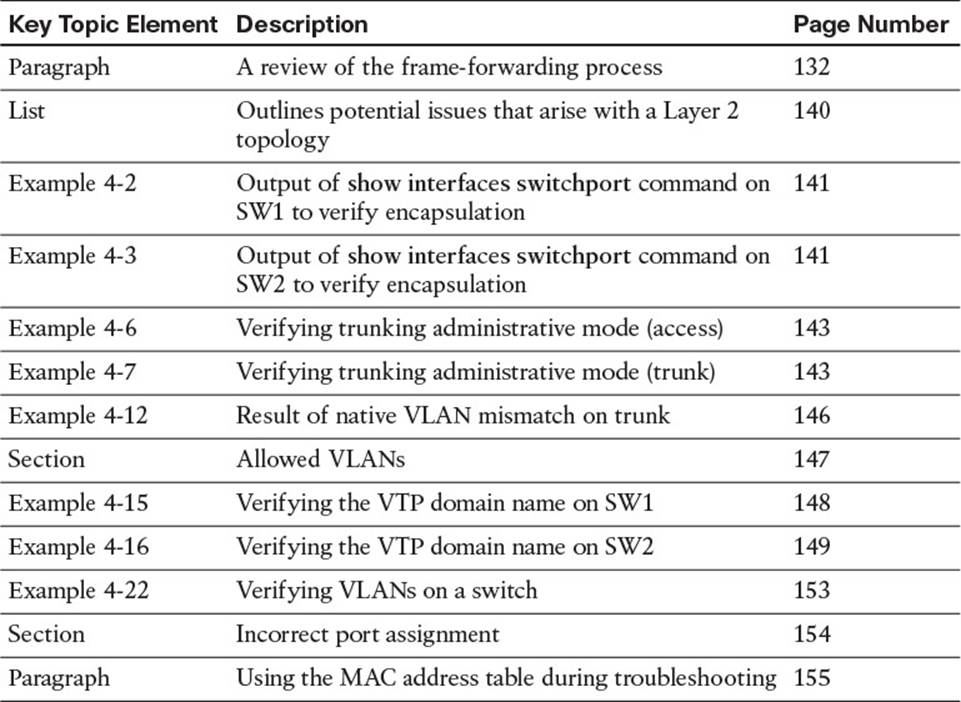
Table 4-3 Key Topics for Chapter 4
Define Key Terms
Define the following key terms from this chapter and check your answers in the glossary:
frame
MAC address table
source MAC
destination MAC
encapsulation
802.1Q
ISL
trunk
access port
dynamic desirable
dynamic auto
native VLAN
VTP
VTP domain name
VLAN
Complete Tables and Lists from Memory
Print a copy of Appendix C, “Memory Tables,” (found on the disc), or at least the section for this chapter, and complete the tables and lists from memory. Appendix D, “Memory Tables Answer Key,” also on the disc, includes completed tables and lists to check your work.
Command Reference to Check Your Memory
This section includes the most important EXEC show commands covered in this chapter. It might not be necessary to memorize the complete syntax of every command, but you should be able to remember the basic keywords that are needed.
To test your memory of the commands, cover the right side of Table 4-4 with a piece of paper, read the description on the left side, and then see how much of the command you can remember.
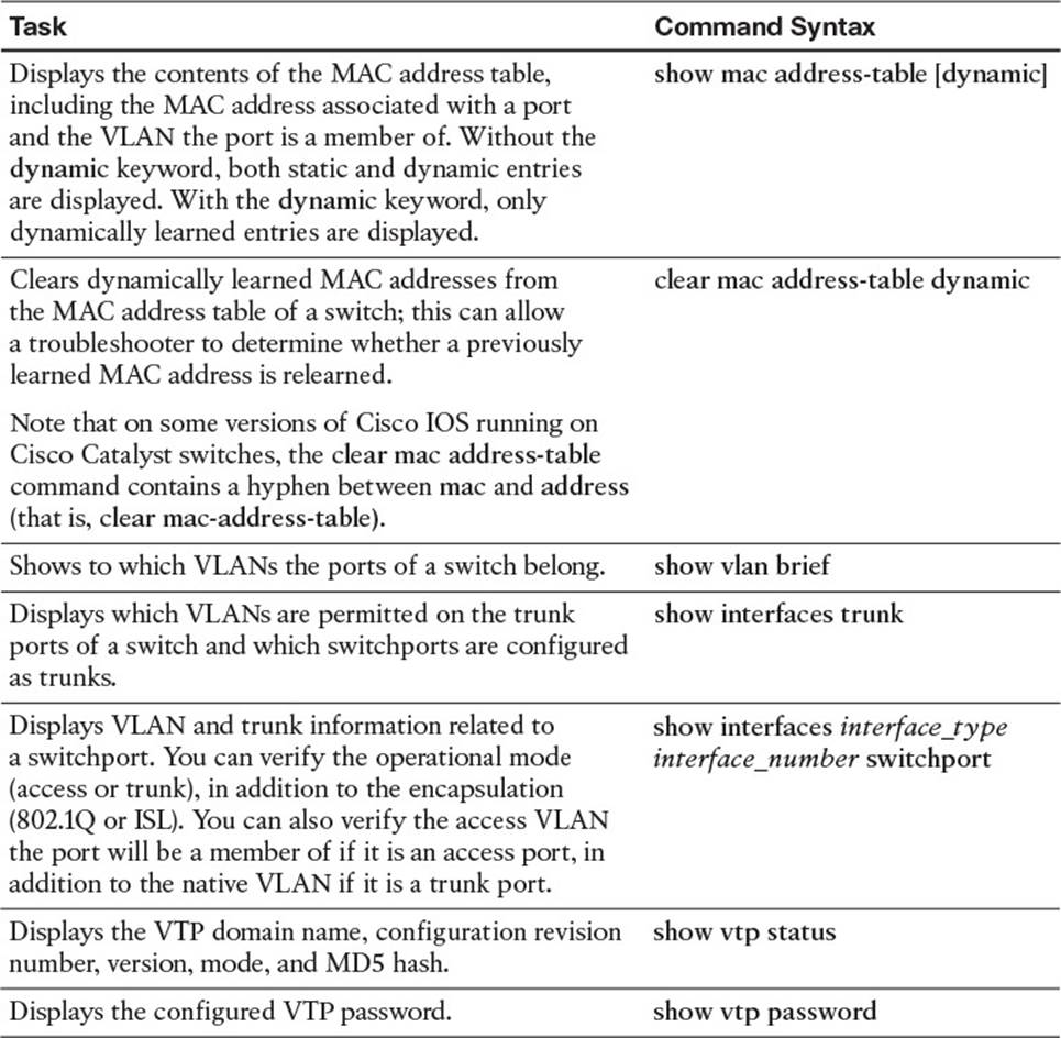
Table 4-4 EXEC CLI show Commands
The 300-135 TSHOOT exam focuses on practical, hands-on skills that are used by a networking professional. Therefore, you should be able to identify the commands needed to successfully troubleshoot switches.
All materials on the site are licensed Creative Commons Attribution-Sharealike 3.0 Unported CC BY-SA 3.0 & GNU Free Documentation License (GFDL)
If you are the copyright holder of any material contained on our site and intend to remove it, please contact our site administrator for approval.
© 2016-2026 All site design rights belong to S.Y.A.