CCNP Routing and Switching TSHOOT 300-135 Official Cert Guide (2015)
Part II. Troubleshooting Cisco Catalyst Switch Features
Chapter 5. Troubleshooting STP and Layer 2 EtherChannel
This chapter covers the following topics:
![]() Spanning-Tree Protocol Overview: This section reviews how STP determines the STP topology from root bridge election to which ports will be nondesignated.
Spanning-Tree Protocol Overview: This section reviews how STP determines the STP topology from root bridge election to which ports will be nondesignated.
![]() Collecting Information About an STP Topology: This section identifies the show commands required to successfully troubleshoot STP issues.
Collecting Information About an STP Topology: This section identifies the show commands required to successfully troubleshoot STP issues.
![]() STP Troubleshooting Issues: This section focuses on what could happen if STP is not behaving as expected.
STP Troubleshooting Issues: This section focuses on what could happen if STP is not behaving as expected.
![]() Troubleshooting STP Features: This section reviews STP features such as PortFast, BPDU Guard, Root Guard, and BPDU Filter. It also identifies the show commands that can help during the troubleshooting process.
Troubleshooting STP Features: This section reviews STP features such as PortFast, BPDU Guard, Root Guard, and BPDU Filter. It also identifies the show commands that can help during the troubleshooting process.
![]() STP Trouble Tickets: This section provides trouble tickets that demonstrate how a structured troubleshooting process can be used to solve a reported problem.
STP Trouble Tickets: This section provides trouble tickets that demonstrate how a structured troubleshooting process can be used to solve a reported problem.
![]() Troubleshooting Layer 2 EtherChannel: This section reviews how Layer 2 EtherChannels are formed and identifies issues that could cause them to fail.
Troubleshooting Layer 2 EtherChannel: This section reviews how Layer 2 EtherChannels are formed and identifies issues that could cause them to fail.
![]() EtherChannel Trouble Tickets: This section provides trouble tickets that demonstrate how a structured troubleshooting process can be used to solve a reported problem.
EtherChannel Trouble Tickets: This section provides trouble tickets that demonstrate how a structured troubleshooting process can be used to solve a reported problem.
Maintaining high availability for today’s enterprise networks is a requirement for many applications, such as voice and e-commerce, which can impact a business’s bottom line if these applications are unavailable for even a short period. To improve availability, many enterprise networks interconnect Layer 2 switches with redundant connections, allowing a single switch or a single link to fail while still maintaining connectivity between any two network endpoints. Such a redundant topology, however, can result in Layer 2 loops, which can cause frames to endlessly circle a LAN (for example, broadcast frames creating a broadcast storm). Therefore, Spanning Tree Protocol (STP) is used to logically break these Layer 2 topological loops by strategically blocking ports, while being able to detect a link failure and bring up a previously blocked switchport to restore connectivity. This chapter reviews the operation of STP and focuses on troubleshooting STP issues.
In addition, this chapter reviews how you can combine multiple physical Layer 2 switchports into a logical EtherChannel bundle. This increases the total bandwidth available on uplinks and tricks STP into thinking there is only one port between the switches instead of multiple ports. As a result, all links are used for traffic forwarding instead of STP blocking them.
“Do I Know This Already?” Quiz
The “Do I Know This Already?” quiz allows you to assess whether you should read this entire chapter thoroughly or jump to the “Exam Preparation Tasks” section. If you are in doubt about your answers to these questions or your own assessment of your knowledge of the topics, read the entire chapter. Table 5-1 lists the major headings in this chapter and their corresponding “Do I Know This Already?” quiz questions. You can find the answers in Appendix A, “Answers to the ‘Do I Know This Already?’ Quizzes.”
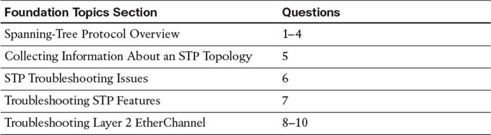
Table 5-1 “Do I Know This Already?” Section-to-Question Mapping
Caution
The goal of self-assessment is to gauge your mastery of the topics in this chapter. If you do not know the answer to a question or are only partially sure of the answer, you should mark that question as wrong for purposes of the self-assessment. Giving yourself credit for an answer that you correctly guess skews your self-assessment results and might provide you with a false sense of security.
1. What determines the switch that will be the STP root bridge for a VLAN?
a. Lowest priority
b. Lowest MAC address
c. Lowest bridge ID
d. Lowest cost
2. What is the STP port type for all ports on a root bridge?
a. Designated port
b. Root port
c. Nondesignated port
d. Nonroot port
3. When determining the root port of a nonroot bridge, if cost is tied, what is referenced next to break the tie?
a. Downstream bridge ID
b. Upstream bridge ID
c. Downstream port ID
d. Upstream port ID
4. What is the maximum age for an STP BPDU in seconds?
a. 2
b. 15
c. 20
d. 50
5. Which two of the following commands are most helpful in determining STP information for a Layer 2 switch?
a. show spanning-tree vlan
b. debug spanning-tree state
c. show spanning-tree interface
d. show port span
6. What are two common issues that could result from an STP failure?
a. Tagged frames being sent into a native VLAN
b. Broadcast storms
c. MAC address table filling to capacity
d. MAC address table corruption
7. Which STP feature ensures that certain ports in the STP topology never become root ports, and if the port receives a superior BPDU it places it in the root inconsistent state?
a. BPDU Guard
b. BPDU Filter
c. Root Guard
d. PortFast
8. Which switch feature allows multiple physical links to be bonded into a logical link?
a. STP
b. EtherChannel
c. PortFast
d. Switch virtual interfaces
9. What must match on physical switchports to successfully form an EtherChannel bundle? (Choose three.)
a. Interface speed
b. Interface mode (access/trunk)
c. Native VLAN
d. STP port cost
10. What combination will successfully form a Cisco proprietary Layer 2 EtherChannel bundle?
a. Active – Passive
b. On – Active
c. Desirable – Auto
d. Desirable – Passive
Foundation Topics
Spanning Tree Protocol Overview
Network availability at Layer 2 of the OSI model requires redundant links between the switches in your topology as well as redundant paths through the network. However, this creates a problem known as a Layer 2 loop, as shown in Figure 5-1. Notice how traffic from SW1 can be sent on both links to SW2 and vice versa. Therefore, traffic sent from SW1 on one link to SW2 can go back to SW1 on the other link and continue indefinitely because there is no mechanism built in to a Layer 2 frame that will stop the frame from looping forever through the network, as shown with Loop1 in Figure 5-1. In addition, notice how there is a larger loop between SW1, SW3, and SW2 (Loop 2). Therefore, frames sent out any of the interfaces interconnecting these switches could loop indefinitely through the network as well. This is different from Layer 3 packets that have atime-to-live (TTL) field that will terminate the packet if it does not reach its destination within a finite number of router hops. Therefore, Layer 2 loops need to be prevented by a protocol known as Spanning Tree Protocol (STP). IEEE 802.1D STP allows a network to physically have Layer 2 loops while strategically blocking data from flowing over one or more switchports to prevent the looping of traffic.
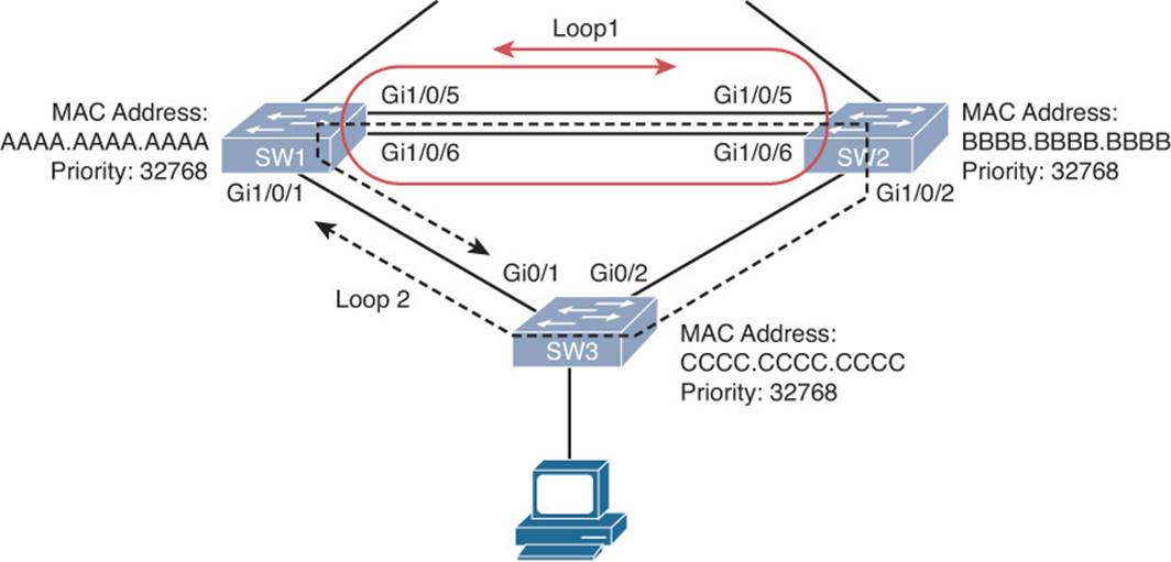
Figure 5-1 Layer 2 Loops
You need to have a solid understanding of how STP makes decisions when troubleshooting Layer 2 issues. Therefore, this section reviews how an STP topology is dynamically formed. In addition, this section discusses commands useful in troubleshooting STP issues.
Reviewing STP Operation
STP uses Bridge Protocol Data Units (BPDUs) to build the STP topology. BPDU packets contain information on ports, addresses, priorities, and costs needed to build the STP topology and ensure that the data ends up where it was intended to go. BPDU messages are exchanged every 2 seconds by default across switches to detect loops in a network topology. The loops are then removed by logically blocking selected bridge interfaces and placing them in the blocked state.
STP prevents Layer 2 loops from occurring in a network, because such an occurrence could result in a broadcast storm or the corruption of a switch’s MAC address table. Switches in an STP topology are classified as one of the following:

![]() Root bridge: The root bridge is a switch elected to act as a reference point for a spanning tree topology. The switch with the lowest bridge ID (BID) is elected as the root bridge. The BID is made up of a priority value (default is 32768) and a MAC address (base Ethernet MAC of switch as shown in the output of the show version command.). The priority is used first; only if the priority is tied between two or more switches will the MAC address be used to break the tie.
Root bridge: The root bridge is a switch elected to act as a reference point for a spanning tree topology. The switch with the lowest bridge ID (BID) is elected as the root bridge. The BID is made up of a priority value (default is 32768) and a MAC address (base Ethernet MAC of switch as shown in the output of the show version command.). The priority is used first; only if the priority is tied between two or more switches will the MAC address be used to break the tie.
![]() Nonroot bridge: All other switches in the STP topology are considered nonroot bridges.
Nonroot bridge: All other switches in the STP topology are considered nonroot bridges.
Figure 5-2 illustrates the root bridge election in a network. Notice that because all bridge priorities are 32768 (default), the switch with the lowest MAC address (that is, SW1) is elected as the root bridge. The MAC address is read left to right. Because a MAC address is based on hexadecimal, lower to higher is 0–9, then A–F.
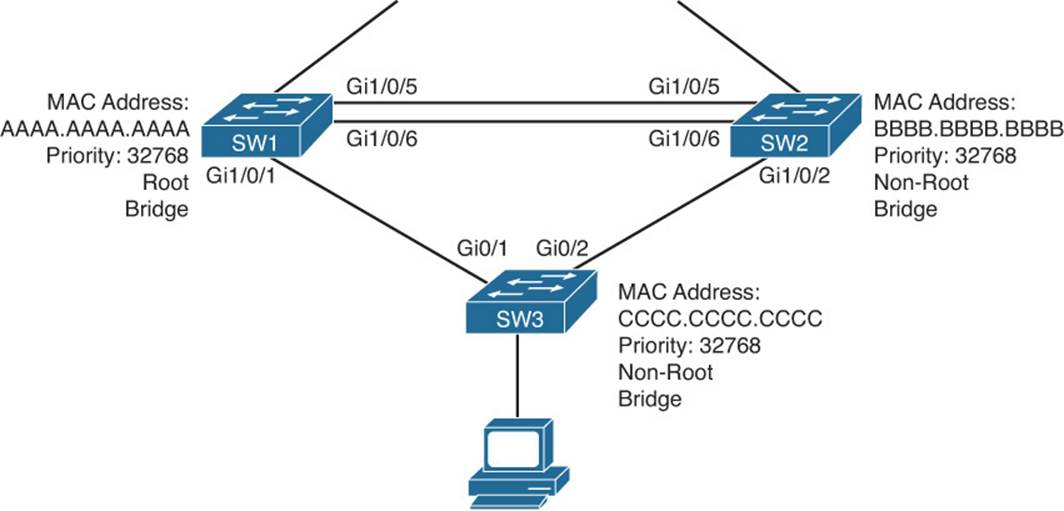
Figure 5-2 Root Bridge Election
Remember the golden rule of STP: Lower is better and ties are not acceptable.
Note
Remembering this rule will help you during each step of the election processes.
Switchports in an STP topology are categorized as one of the following port roles described in Table 5-2 and illustrated in Figure 5-3.
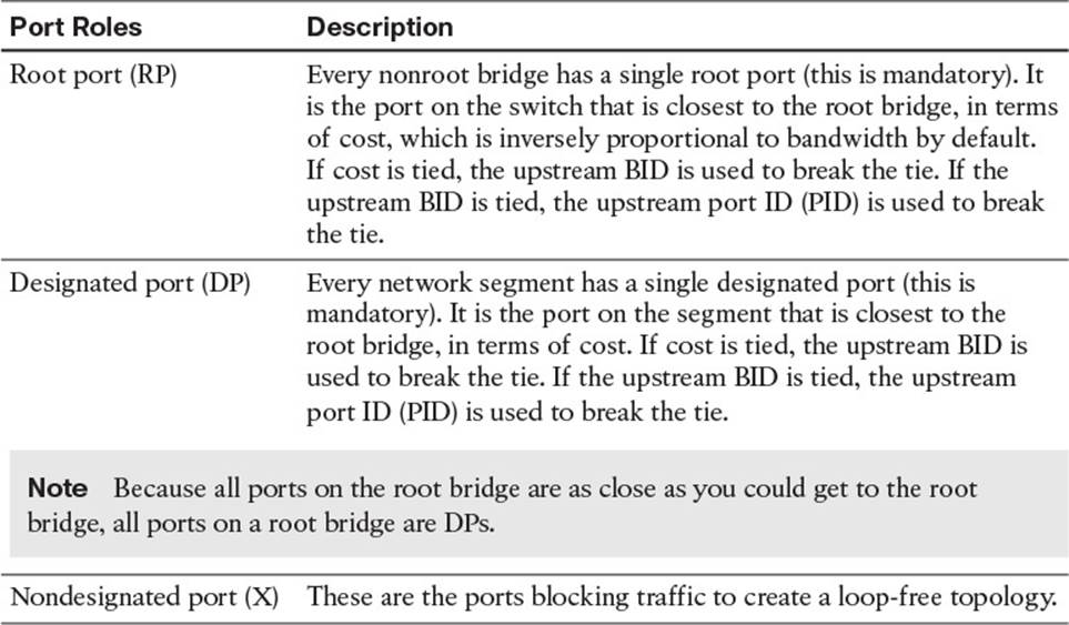
Table 5-2 STP Port Roles
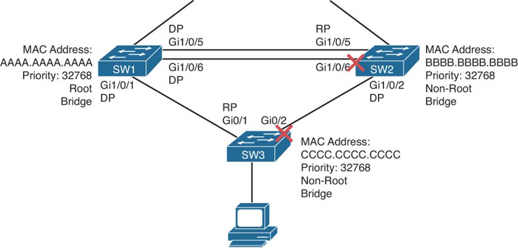
Figure 5-3 STP Port Roles
Table 5-3 shows the default port costs for various link speeds for both 802.1D STP and its successor 802.1D-2004 STP. Notice the higher the speed the lower the cost. Remember that a lower cost is better and that the cost used is the cumulative path cost.
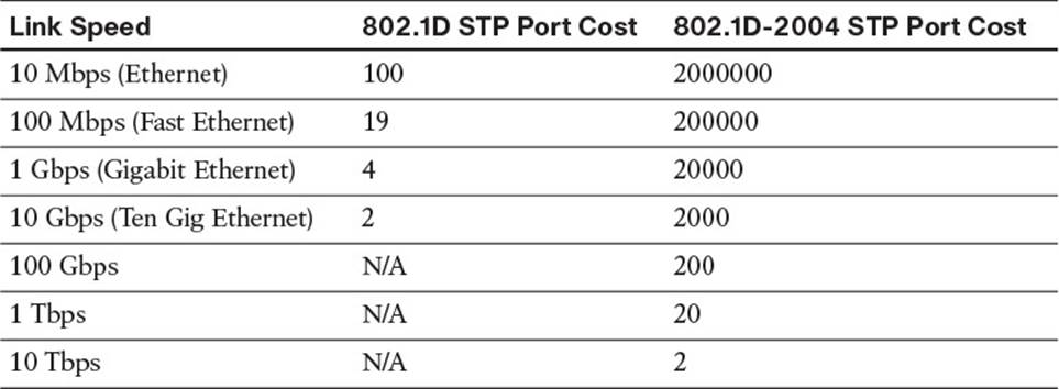
Table 5-3 Default Port Costs
Determining Root Port
Being able to determine why a port has a specific role is important for troubleshooting and tuning the STP topology. Notice the root port for switch SW2 is Gig 1/0/5 in Figure 5-3. Why was it chosen as the root port? If you are not sure, review the following steps for determining the root port on a switch:
1. Identify the port that has the lowest cumulative cost path to the root bridge. In Figure 5-3, the total cost from SW2 Gi1/0/5 to the root bridge is 4. The total cost from SW2 Gi1/0/6 to the root bridge is 4. The total cost from SW2 Gi1/0/2 to the root bridge is (4 + 4) 8. Remember, lower is better and ties are not acceptable. In this case, we have a tie for the lowest value at 4. When the path cost is tied, you use the lowest upstream BID as a tiebreaker. Proceed to Step 2.
2. Identify the SW2 port (Gi1/0/5 or Gi1/0/6) that receives a BPDU with a lower upstream BID. In this case, the BID received in the BPDUs from SW1 is tied. The priority is checked first for the BPDUs received by SW2 on Gi1/0/5 and Gi1/0/6 from SW1. In Figure 5-3, the BPDUs will have the same priority because they are sent from the same switch (SW1) with a priority of 32768. Next is to compare the MAC addresses listed in the BPDUs. Again, they are both the same because switches use the same base Ethernet MAC address for all BPDUs sent on all interfaces. Therefore, both received BPDUs from SW1 have a priority of 32768 and a MAC of AAAA.AAAA.AAAA. When the upstream BID is tied, you use the upstream PID to break the tie. Proceed to Step 3.
3. Identify the port that receives a BPDU with a lower upstream PID. When SW1 sends BPDUs, it includes a PID. This PID includes a port priority number and an interface number. The priority number can be manually changed (default 128); however, the interface number cannot. It is generated by the switch to identify the port. In Figure 5-3, SW1 would more than likely have a PID of 128.5 on Gi1/0/5 and 128.6 on Gi1/0/6 by default. As a result, when SW2 receives the BPDUs from SW1, the received BPDU on Gi1/0/5 has a PID attached of 128.5 and the received BPDU on Gi1/0/6 has a PID attached of 128.6. Lower is better; therefore, SW2 Gi1/0/5 is elected the root port based on the PID value sent from SW1 in the BPDUs.
Focusing on SW3 in Figure 5-3 shows a total cost of 4 to get to the root bridge using Gi0/1 and a total cost of 8 using Gi0/2. Therefore, Gi0/1 is elected as the root port.
Determining Designated Port
When determining the designated ports for each segment, you follow the same steps listed in the previous section for the root port election. Remember that every port on the root bridge will be a designated port. Therefore, without performing any calculations, you already know a few designated ports in the topology. As a result, in Figure 5-3 the only link/segment remaining without a designated port is the segment between SW2 and SW3. We can see that it is already labeled as Gi1/0/2 on SW2, but why? Let’s walk through the steps together:
1. Identify the port on the segment with the lowest cumulative cost back to the root bridge. SW2 Gi1/0/2 has a cumulative cost (including the cost of the segment itself) of (4 + 4) = 8. SW3 Gi0/2 has a cumulative cost (including the cost of the segment itself) of (4 + 4) = 8. We have a tie, so we move on to Step 2.
2. Find the upstream switch with the lowest BID. This is tricky if you do not know where to position yourself. Here is my trick. Pretend you are standing in the middle of the segment between SW2 and SW3. Point to SW2. What is the priority? 32768. Point to SW3. What is the priority? 32768. We have a tie. We then need to look at the MAC address. Still standing in the middle of the segment, point to SW2. What is the MAC address? BBBB.BBBB.BBBB. Point to SW3. What is the MAC address? CCCC.CCCC.CCCC. Which one is lower? It is the MAC address of SW2.
Therefore, SW2’s port Gi1/0/2 is the designated port for the segment between SW2 and SW3.
Determining Nondesignated Port
Every other port that is not a root port or a designated port is a nondesignated port and will be blocking traffic, as depicted in Figure 5-3. Nondesignated ports do not forward traffic during normal operation but do receive BPDUs to determine the state of the STP topology. If a link in the topology goes down, the nondesignated port indirectly detects the link failure from BPDUs and determines whether it needs to transition to the forwarding state or not to ensure network availability while preventing loops.
If a nondesignated port does need to transition to the forwarding state, the type of STP in use will determine how long it takes to transition to the forwarding state. STP (802.1D), Common Spanning Tree (CST), and Cisco’s implementation of STP (PVST+) transition through the following states:
![]() Blocking: The port remains in the blocking state until it needs to transition. If it needs to transition, it will wait for 20 seconds by default. This is known as the max age time. It is essentially the time-to-live of a BPDU. A BPDU is only valid for 20 seconds. If a new BDPU is not received before the max age time expires, the switch considers the BPDU stale and transitions to the listening state. During the blocking state, a nondesignated port evaluates BPDUs in an attempt to determine its role in the spanning tree.
Blocking: The port remains in the blocking state until it needs to transition. If it needs to transition, it will wait for 20 seconds by default. This is known as the max age time. It is essentially the time-to-live of a BPDU. A BPDU is only valid for 20 seconds. If a new BDPU is not received before the max age time expires, the switch considers the BPDU stale and transitions to the listening state. During the blocking state, a nondesignated port evaluates BPDUs in an attempt to determine its role in the spanning tree.
![]() Listening: The port remains in this state for 15 seconds by default (15 seconds is known as the forward delay). During this time, the port sources BPDUs, which inform adjacent switches of the port’s intent to forward data. In addition, it receives BDPUs from other switches, which will help in the building of the STP topology and determining the root ports and designated ports.
Listening: The port remains in this state for 15 seconds by default (15 seconds is known as the forward delay). During this time, the port sources BPDUs, which inform adjacent switches of the port’s intent to forward data. In addition, it receives BDPUs from other switches, which will help in the building of the STP topology and determining the root ports and designated ports.
![]() Learning: The port moves from the listening state to the learning state and remains in this state for 15 seconds by default. During this time, the port begins to add entries to its MAC address table while still sending and receiving BPDUs to ensure that the decisions made in relation to the STP topology are still accurate.
Learning: The port moves from the listening state to the learning state and remains in this state for 15 seconds by default. During this time, the port begins to add entries to its MAC address table while still sending and receiving BPDUs to ensure that the decisions made in relation to the STP topology are still accurate.
![]() Forwarding: The port moves from the learning state to the forwarding state and begins to forward frames while learning MAC addresses and sending and receiving BPDUs. Root ports and designated ports are in this state.
Forwarding: The port moves from the learning state to the forwarding state and begins to forward frames while learning MAC addresses and sending and receiving BPDUs. Root ports and designated ports are in this state.
As you can see, the total time to transition from the blocking state to the forwarding state is 50 seconds with 802.1D.
Rapid Spanning Tree Protocol (802.1w) and Multiple Spanning Tree Protocol (802.1s) use a handshaking mechanism rather than timers as their primary method of convergence. Therefore, convergence is 5 seconds or less. If the handshaking mechanism fails, 802.1w and 802.1s rely on the same timers as 802.1D as backup. In addition, if a neighboring switch is using 802.1D, timers are used with them for backward compatibility.
Collecting Information About an STP Topology
Cisco Catalyst switches will dynamically form a spanning-tree topology using default port costs and bridge priorities right out of the box. You do not have to do anything. However, the resulting STP topology might not be the best for your organization. For example, you might want to influence a particular switch to become a root bridge to ensure optimal traffic forwarding through a Layer 2 topology. Or, you might want traffic for one VLAN to take a certain path while traffic for other VLANs takes a different path. If you ever need to manipulate STP, which will more than likely be the case, you need to know the current topology and how to modify it. This section identifies the various methods we can use to gather information about our STP topology.
Gathering STP Information
When troubleshooting an STP topology, one of the first tasks is to learn which switch is acting as the root bridge, in addition to learning the port roles on the various switches in the topology. Not only is this information important in understanding how frames are currently flowing through the topology, but comparing the current STP state of a topology to a baseline state can also provide clues as to the underlying cause of an issue, such as suboptimal traffic forwarding.
The show spanning-tree [vlan {vlan_id}] command can display information about the STP state of a switch. Consider Example 5-1, which shows the output from the show spanning-tree vlan 1 command. The VLAN is specified because Cisco Catalyst switches use Per-VLAN Spanning Tree + (PVST+) by default. PVST+ allows a switch to run a separate STP instance for each VLAN. The output in Example 5-1 shows that SW3 is not the root bridge for the spanning tree of VLAN 1. This is because the MAC address of the root bridge (Root ID) differs from the MAC address of SW3 (Bridge ID). In addition, there is a root port on the switch, which a root bridge cannot have, and it does not state that this switch is the root bridge. The Gig 0/1 port of switch SW3 is the root port of the switch, whereas port Gig 0/2 is a nondesignated port. (That is, it is a blocking port.) Note that the port cost of Gig 0/1 is 4, and the port cost of Gig 0/2 is 4 as well.
Example 5-1 show spanning-tree vlan Command Output
SW3#show spanning-tree vlan 1
VLAN0001
Spanning tree enabled protocol ieee
Root ID Priority 32768
Address aaaa.aaaa.aaaa
Cost 4
Port 25 (GigabitEthernet0/1)
Hello Time 2 sec Max Age 20 sec Forward Delay 15 sec
Bridge ID Priority 32769 (priority 32768 sys-id-ext 1)
Address cccc.cccc.cccc
Hello Time 2 sec Max Age 20 sec Forward Delay 15 sec
Aging Time 300
Interface Role Sts Cost Prio.Nbr Type
-----------------------------------------------------------------------
Gi0/1 Root FWD 4 128.25 P2p
Gi0/2 Altn BLK 4 128.26 P2p
The show spanning-tree interface interface_type interface_number detail command, as shown in Example 5-2, displays the number of BPDUs sent and received, the port identifier, and the designated root and designated bridge priority and MAC address. Note that in a stable topology, root ports should only receive BPDUs, and designated ports should only send BPDUs. Therefore, if you see a high number of sent and received BPDUs on ports, you have an unstable STP topology and need to determine why this is so and fix it.
Example 5-2 show spanning-tree interface interface_type interface_number detail Command Output
SW3#show spanning-tree interface gig 0/1 detail
Port 25 (GigabitEthernet0/1) of VLAN0001 is root forwarding
Port path cost 4, Port priority 128, Port Identifier 128.25.
Designated root has priority 32768, address aaaa.aaaa.aaaa
Designated bridge has priority 32768, address aaaa.aaaa.aaaa
Designated port id is 128.1, designated path cost 0
Timers: message age 2, forward delay 0, hold 0
Number of transitions to forwarding state: 1
Link type is point-to-point by default
BPDU: sent 1, received 1245
Gathering MSTP Information
Multiple Spanning Tree Protocol (MSTP) allows you to group multiple VLANs into a single STP instance. This significantly improves STP in end-to-end VLAN deployments where a large number of VLANs are maintained by many switches. When you group various VLANs together into the same instance, the CPU does not have to process BPDUs for all the different VLANs. In fact, with MSTP, only MST0 (known as the IST) is used to send BPDUs, and all the other MST instances are listed in the MST0 BPDUs as M-records. This improves CPU performance.
Consider this. If you have 100 VLANs and you only have 2 uplinks from an access layer switch to the distribution layer, you can group half the VLANs in one instance and the other half in another instance. You can then manipulate who the root bridge is so that one instance ends up using one uplink and the other instance uses the other uplink. You have just achieved load sharing and reduced the number of STP instances from 100 to 2, thus conserving CPU resources. To ensure you optimize load sharing, you need to gather statistics about the traffic flowing through the networking on a VLAN-by-VLAN basis and make sure that you do not place heavily used VLANs in the same MSTP instance or you will not achieve optimal load sharing.
When deploying and troubleshooting MSTP, you have to remember these three very important rules for switches in the same region:
![]() The MSTP region name must match.
The MSTP region name must match.
![]() The MSTP revision number must match.
The MSTP revision number must match.
![]() The MSTP instance to VLAN mappings must be the same on all the switches.
The MSTP instance to VLAN mappings must be the same on all the switches.
If any of the items listed do not match exactly, the digest that is sent within an MSTP BPDU will be different, and the switches will consider each other to be in a different MSTP region and therefore produce different spanning-tree topologies than the administrator envisioned. To verify the current region name, revision number, and VLAN to instance mappings on a switch, issue the show spanning-tree mst configuration command, as shown in Example 5-3.
Example 5-3 show spanning-tree mst configuration Command Output
SW3#show spanning-tree mst configuration
Name TSHOOT
Revision 10 Instances configured 2
Instance Vlans mapped
-------- -------------------------------------------------------
0 1-9,11-19,21-99,101-199,201-4094
1 10,100
2 20,200
------------------------------------------------------------------
STP Troubleshooting Issues
If STP fails to operate correctly, Layer 2 frames can endlessly circulate through a network because of the loop created. This behavior can lead to issues such as MAC address table corruption and broadcast storms. In this section we analyze the results of an STP failure.
Corruption of a Switch’s MAC Address Table
Recall from Chapter 4, “Troubleshooting Layer 2 Trunks, VTP, and VLANs,” that the MAC address table determines what a switch will do with a frame. Therefore, this table needs to be accurate. A switch will dynamically learn what MAC addresses are reachable off its ports; however, in the event of an STP failure, the MAC address table of a switch can become corrupt. To illustrate, consider Figure 5-4. PC1 is transmitting traffic to PC2. When the frame sent from PC1 is transmitted on segment A, the frame is seen on the Gig 0/1 ports of switches SW1 and SW2, causing both switches to add an entry to their MAC address tables (AAAA.AAAA.AAAA is associated with port Gig 0/1). Because STP is not functioning, both switches then forward the frame out segment B. As a result, PC2 receives two copies of the frame. Also, switch SW1 sees the frame forwarded out the Gig 0/2 port of switch SW2. Because the frame has a source MAC address of AAAA.AAAA.AAAA, switch SW1 incorrectly updates its MAC address table indicating that a MAC address of AAAA.AAAA.AAAA resides off port Gig 0/2. Similarly, switch SW2 sees the frame forwarded onto segment B by switch SW1 on its Gig 0/2 port. Therefore, switch SW2 also incorrectly updates its MAC address table. As a result of this, all frames destined to AAAA.AAAA.AAAA will be forwarded out Gig0/2 and never reach PC1.
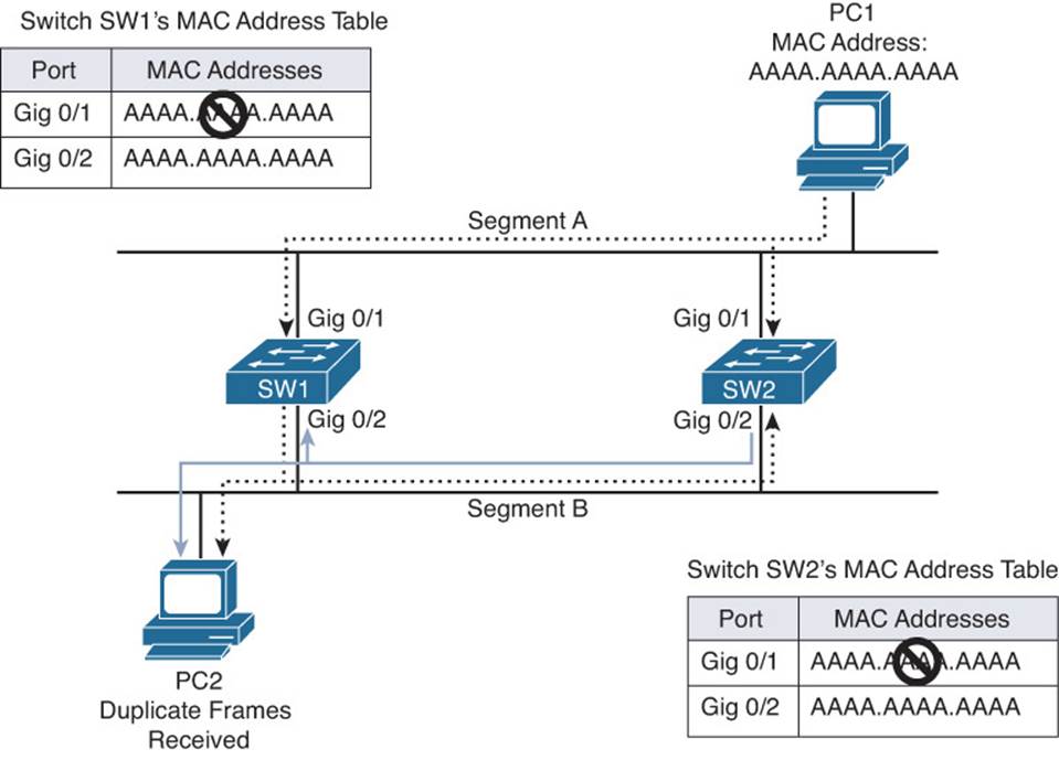
Figure 5-4 MAC Address Table Corruption
That was a simplified example of what would occur. In reality, as frames continue to propagate through the network, not only would the MAC address table be corrupt, it would be unstable. At one moment AAAA.AAAA.AAAA would be learned on Gig0/1, then Gig0/2, then back on Gig0/1, then Gig0/2.
You will be able to recognize this issue because syslog messages will be generated identifying that you have MAC addresses flapping between different ports on the same switch. The following syslog messages show that the MAC addresses are being learned on Gi0/1 and Gi0/2, and this would occur only if there were a loop allowing the same frame to be seen on multiple interfaces:
%SW_MATM-4-MACFLAP_NOTIF: Host 0000.5e00.0114 in vlan 20 is flapping between port
Gi0/1 and port Gi0/2
%SW_MATM-4-MACFLAP_NOTIF: Host 8049.7111.7e05 in vlan 502 is flapping between port
Gi0/1 and port Gi0/2
%SW_MATM-4-MACFLAP_NOTIF: Host 0050.b60c.f21b in vlan 20 is flapping between port
Gi0/1 and port Gi0/2
Broadcast Storms
As previously mentioned, when a switch receives a broadcast frame (that is, a frame destined for a MAC address of FFFF.FFFF.FFFF), the switch floods the frame out all switchports except the port on which the frame was received. The same is true for unknown unicast and multicast frames. Because a Layer 2 frame does not have a TTL field, a broadcast frame endlessly circulates through the Layer 2 topology, consuming resources on both switches and attached devices (for example, user PCs).
Figure 5-5 illustrates how a broadcast storm can form in a Layer 2 topology when STP is not functioning correctly.
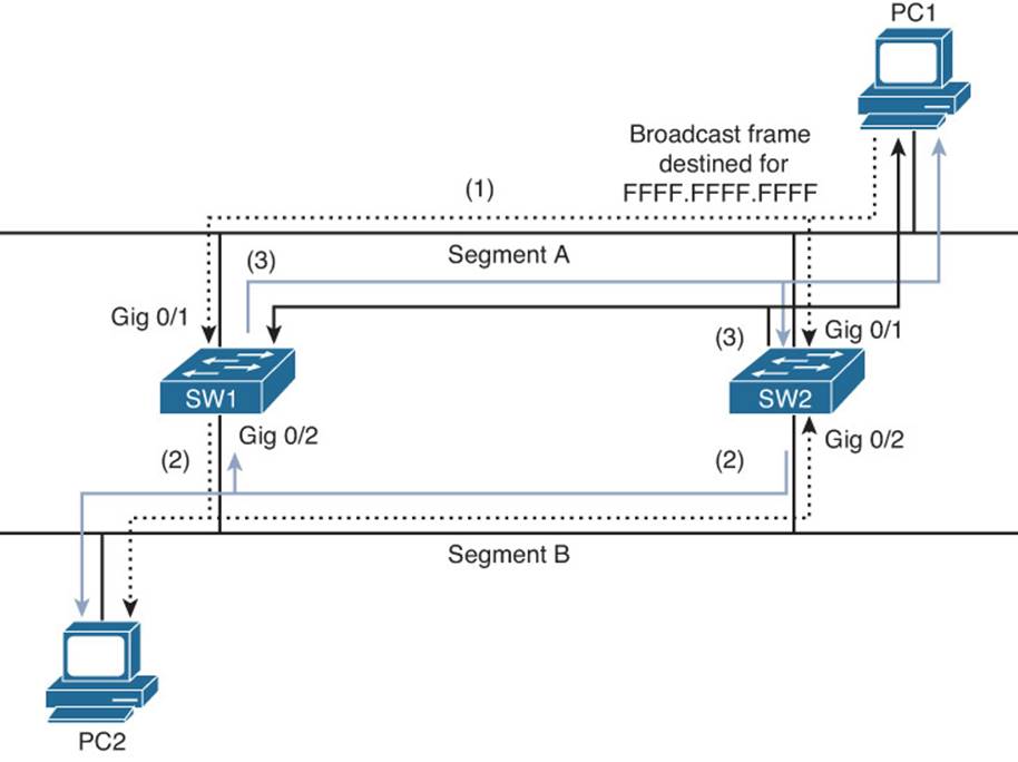
Figure 5-5 Broadcast Storm
1. PC1 sends a broadcast frame onto Segment A, and the frame enters each switch on port Gig 0/1.
2. Both switches flood a copy of the broadcast frame out of their Gig 0/2 ports (that is, on to Segment B), causing PC2 to receive two copies of the broadcast frame.
3. Both switches receive a copy of the broadcast frame on their Gig 0/2 ports (that is, from Segment B) and flood the frame out of their Gig 0/1 ports (that is, onto Segment A), causing PC1 to receive two copies of the broadcast frame.
This behavior continues, as the broadcast frame copies continue to loop through the network. The performance of PC1 and PC2 is impacted, because they also continue to receive copies of the broadcast frame that they must process.
A common complaint you will receive from multiple network users at the same time when there is an STP issue is, the network/Internet is really slow. This is because of the broadcast storm consuming the majority of the resources in the Layer 2 network. Therefore, the frames going to the resources that the users need to access are not making it to the destination or are taking a really long time because the network is congested.
Troubleshooting STP Features
STP relies on many features to protect the topology. These features are not enabled by default. Knowing how to troubleshoot these features is important to ensure the STP topology is functioning as it should. This section discusses these features and reviews the commands needed to troubleshoot them.
PortFast
The PortFast feature is used to transition a switchport to the forwarding state as soon as the switchport is enabled. (A device is plugged in, and the switchport is not shut down.) If you are using PortFast with PVST+, RPVST+, or MSTP, when a BPDU is received on a PortFast-enabled switchport, the switchport will immediately transition out of the PortFast state and become a normal switchport. This ensures that it transitions through the necessary states and processes before going to the forwarding state to ensure that a loop is not caused. You can enable PortFast on an interface-by-interface basis with the spanning-tree portfast interface command or globally with the spanning-tree portfast default command, which will enable it on all nontrunking switchports. Example 5-4 identifies three ways to verify PortFast is enabled on an interface.
Example 5-4 Verifying PortFast-Enabled Interfaces
SW3#show run interface fa0/1
Building configuration...
Current configuration : 108 bytes
!
interface FastEthernet0/1
switchport access vlan 10
switchport mode access
spanning-tree portfast
end
SW3#show spanning-tree interface fastEthernet 0/1 portfast
VLAN0010 enabled
SW3#show spanning-tree interface fastEthernet 0/1 detail
Port 1 (FastEthernet0/1) of VLAN0010 is designated forwarding
Port path cost 19, Port priority 128, Port Identifier 128.1.
Designated root has priority 10, address 2893.fe3a.e300
Designated bridge has priority 32778, address 081f.f34e.b800
Designated port id is 128.1, designated path cost 4
Timers: message age 0, forward delay 0, hold 0
Number of transitions to forwarding state: 1
The port is in the portfast mode
Link type is point-to-point by default
BPDU: sent 11, received 0
If you enabled PortFast globally, you can use another show command to verify that PortFast was enabled globally: show spanning-tree summary, as shown in Example 5-5. Notice that PortFast Default is enabled. Also notice how the output of the command show spanning-tree interface fastEthernet 0/1 detail in Example 5-5 is different when compared to Example 5-4. In Example 5-5, it states, “The port is in the portfast mode by default,” which indicates that PortFast was enabled globally.
Example 5-5 Verifying Globally Enabled PortFast Interfaces
SW3#show spanning-tree summary
Switch is in rapid-pvst mode
Root bridge for:
EtherChannel misconfig guard is enabled
Extended system ID is enabled
Portfast Default is enabled
PortFast BPDU Guard Default is disabled
Portfast BPDU Filter Default is disabled
Loopguard Default is disabled
UplinkFast is disabled
BackboneFast is disabled
Configured Pathcost method used is short
SW3#show spanning-tree interface fastEthernet 0/1 detail
Port 1 (FastEthernet0/1) of VLAN0010 is designated forwarding
Port path cost 19, Port priority 128, Port Identifier 128.1.
Designated root has priority 10, address 2893.fe3a.e300
Designated bridge has priority 32778, address 081f.f34e.b800
Designated port id is 128.1, designated path cost 4
Timers: message age 0, forward delay 0, hold 0
Number of transitions to forwarding state: 1
The port is in the portfast mode by default
Link type is point-to-point by default
Bpdu filter is enabled by default
BPDU: sent 11, received 0
One of the easiest ways to confirm that a switchport is indeed enabled for PortFast is to review the output of show spanning-tree. As shown in Example 5-6, Fa 0/1 is listed as an Edge port indicated that PortFast is enabled on the interface.
Example 5-6 Using show spanning-tree to Verify PortFast Status
SW3#show spanning-tree
...output omitted...
Interface Role Sts Cost Prio.Nbr Type
------------------- ---- --- --------- -------- ----------------------
Fa0/1 Desg FWD 19 128.1 P2p Edge
Fa0/2 Desg FWD 19 128.2 P2p Edge
Gi0/1 Root FWD 4 128.25 P2p
Gi0/2 Altn BLK 4 128.26 P2p
...output omitted...
BPDU Guard
BPDU Guard is used to enforce STP domain borders. This ensures that the STP topology remains predictable. When a BPDU is received on a switchport enabled with BPDU Guard, the port will be disabled and placed in the err-disabled state. To verify which ports are in the err-disabled state, issue the command show interfaces status, as shown in Example 5-7. In this example, Fast Ethernet 0/1 is in the err-disabled state. In addition, if you are tracking syslog messages, you will receive the following:
%SPANTREE-2-BLOCK_BPDUGUARD: Received BPDU on port Fa0/1 with BPDU Guard enabled.
Disabling port.
%PM-4-ERR_DISABLE: bpduguard error detected on Fa0/1, putting Fa0/1 in err-disable
state
%LINK-3-UPDOWN: Interface FastEthernet0/1, changed state to down
Example 5-7 show interfaces status Command Output
SW3#show interfaces status
Port Name Status Vlan Duplex Speed Type
Fa0/1 err-disabled 10 auto auto 10/100BaseTX
Fa0/2 connected 10 a-full a-100 10/100BaseTX
Fa0/3 notconnect 1 auto auto 10/100BaseTX
Fa0/4 notconnect 1 auto auto 10/100BaseTX
Fa0/5 notconnect 1 auto auto 10/100BaseTX
Fa0/6 notconnect 1 auto auto 10/100BaseTX
Like PortFast, BPDU Guard can be enabled on an interface-by-interface basis with the spanning-tree bpduguard enable interface command or globally with the spanning-tree portfast bpduguard default global configuration command. The global command will only enable it on PortFast-enabled interfaces.
You can verify whether BPDU Guard is enabled globally using the commands show spanning-tree summary and show spanning-tree interface interface_type interface_number detail, as depicted in Example 5-8.
Example 5-8 Verifying BPDU Guard Is Enabled Globally
SW3#show spanning-tree summary
Switch is in rapid-pvst mode
Root bridge for:
Extended system ID is enabled
Portfast Default is disabled
PortFast BPDU Guard Default is enabled
Portfast BPDU Filter Default is disabled
Loopguard Default is disabled
EtherChannel misconfig guard is enabled
UplinkFast is disabled
BackboneFast is disabled
Configured Pathcost method used is short
...output omitted...
SW3#show spanning-tree interface fastethernet 0/1 detail
Port 1 (FastEthernet0/1) of VLAN0010 is designated forwarding
Port path cost 19, Port priority 128, Port Identifier 128.1.
Designated root has priority 10, address 2893.fe3a.e300
Designated bridge has priority 32778, address 081f.f34e.b800
Designated port id is 128.1, designated path cost 4
Timers: message age 0, forward delay 0, hold 0
Number of transitions to forwarding state: 1
The port is in the portfast mode
Link type is point-to-point by default
Bpdu guard is enabled by default
BPDU: sent 11, received 0
You can verify if BPDU Guard has been enabled on an interface basis with the show spanning-tree interface interface_type interface_number detail command and the show run interface interface_type interface_number command, as shown in Example 5-9.
Example 5-9 Verifying BPDU Guard Is Enabled on an Interface
SW3#show spanning-tree interface fastethernet 0/1 detail
Port 1 (FastEthernet0/1) of VLAN0010 is designated forwarding
Port path cost 19, Port priority 128, Port Identifier 128.1.
Designated root has priority 10, address 2893.fe3a.e300
Designated bridge has priority 32778, address 081f.f34e.b800
Designated port id is 128.1, designated path cost 4
Timers: message age 0, forward delay 0, hold 0
Number of transitions to forwarding state: 1
The port is in the portfast mode
Link type is point-to-point by default
Bpdu guard is enabled
BPDU: sent 4, received 0
SW3#show run interface fastethernet 0/1
Building configuration...
Current configuration : 140 bytes
!
interface FastEthernet0/1
switchport access vlan 10
switchport mode access
spanning-tree portfast
spanning-tree bpduguard enable
end
To recover from the err-disabled state, remove the device that is sending the rogue BPDUs, and then manually disable and enable the err-disabled interface with the shutdown and then no shutdown commands. Or, you can set up an err-disable recovery feature that will attempt to automatically enable the interface at defined intervals. If the rogue BPDUs are still detected, the interface will go back into the err-disabled state. If the rogue BPDUs are not detected anymore, the interface will automatically recover. To enable the err-disable recovery feature for BPDU Guard, use the errdisable recovery cause bpduguard global configuration command.
BPDU Filter
BPDU Filter is designed to suppress the sending and receiving of BPDUs on an interface. This would be for security reasons. For example, there is no need to send BPDUs out an interface that is connected to an end station or a router. Doing so allows the end station to collect the data in the BPDUs and potentially launch an attack against the STP topology. How you enable it determines the extent of BDPUs that will be suppressed:
![]() If you enable it globally, with the spanning-tree portfast bpdufilter default command, BPDU Filter will be enabled on all PortFast-enabled interfaces and will suppress the sending of BPDUs out an interface. However, if a BPDU is received on an interface, it will process it normally and, if necessary, transition the interface through the normal STP states/processes.
If you enable it globally, with the spanning-tree portfast bpdufilter default command, BPDU Filter will be enabled on all PortFast-enabled interfaces and will suppress the sending of BPDUs out an interface. However, if a BPDU is received on an interface, it will process it normally and, if necessary, transition the interface through the normal STP states/processes.
![]() If you enable BPDU Filter manually on an interface with the spanning-tree bpdufilter enable command, it suppresses the sending and receiving of BPDUs. This is not recommended because any received BPDUs are ignored and may result in a Layer 2 loop because the interface is automatically in the forwarding state.
If you enable BPDU Filter manually on an interface with the spanning-tree bpdufilter enable command, it suppresses the sending and receiving of BPDUs. This is not recommended because any received BPDUs are ignored and may result in a Layer 2 loop because the interface is automatically in the forwarding state.
You can verify whether BPDU Filter is enabled globally with the show spanning-tree summary command and the show spanning-tree interface interface_type interface_number detail command, as shown in Example 5-10. If it is enabled on an interface-by-interface basis, which is not recommended, you can verify BPDU Filter with the show spanning-tree interface interface_type interface_number detail command and the show run interface interface_type interface_number command, as shown in Example 5-11.
Example 5-10 Verifying BPDU Filter Is Enabled Globally
SW3#show spanning-tree summary
Switch is in rapid-pvst mode
Root bridge for:
Extended system ID is enabled
Portfast Default is disabled
PortFast BPDU Guard Default is disabled
Portfast BPDU Filter Default is enabled
Loopguard Default is disabled
EtherChannel misconfig guard is enabled
UplinkFast is disabled
BackboneFast is disabled
Configured Pathcost method used is short
SW3#show spanning-tree interface fastethernet 0/1 detail
Port 1 (FastEthernet0/1) of VLAN0010 is designated forwarding
Port path cost 19, Port priority 128, Port Identifier 128.1.
Designated root has priority 10, address 2893.fe3a.e300
Designated bridge has priority 32778, address 081f.f34e.b800
Designated port id is 128.1, designated path cost 4
Timers: message age 0, forward delay 0, hold 0
Number of transitions to forwarding state: 1
The port is in the portfast mode
Link type is point-to-point by default
Bpdu guard is enabled
Bpdu filter is enabled by default
BPDU: sent 11, received 0
Example 5-11 Verifying BPDU Filter Is Enabled on an Interface
SW3#show spanning-tree interface fastethernet 0/1
Port 1 (FastEthernet0/1) of VLAN0010 is designated forwarding
Port path cost 19, Port priority 128, Port Identifier 128.1.
Designated root has priority 10, address 2893.fe3a.e300
Designated bridge has priority 32778, address 081f.f34e.b800
Designated port id is 128.1, designated path cost 4
Timers: message age 0, forward delay 0, hold 0
Number of transitions to forwarding state: 1
The port is in the portfast mode
Link type is point-to-point by default
Bpdu guard is enabled
Bpdu filter is enabled
BPDU: sent 18, received 0
SW3#show run interface fastethernet 0/1
Building configuration...
Current configuration : 173 bytes
!
interface FastEthernet0/1
switchport access vlan 10
switchport mode access
spanning-tree portfast
spanning-tree bpdufilter enable
spanning-tree bpduguard enable
end
If you are experiencing a Layer 2 loop in your topology, check whether BPDUFilter was enabled on an interface. If so, it would be suppressing the sending and receiving of BPDUs. As a result, a port within the topology is in the forwarding state causing a Layer 2 loop when it should be in the blocking state.
Root Guard
Root Guard is designed to protect the root bridge by ensuring that certain ports on nonroot bridges are prevented from becoming root ports. If you recall, the root port on a switch points to the root bridge. If a rogue switch is introduced to the STP topology with a superior BID, it can become the root bridge, and root ports would change on all the other switches so that the new root ports point to the rogue root bridge.
Root Guard stops this from happening by ignoring superior BPDUs that are received on the Root Guard-enabled ports and placing the port in the spanning-tree inconsistent state. Because Root Guard is enabled on an interface-by-interface basis with the command spanning-tree guard root, the command show spanning-tree interface interface_type interface_number detail, as shown in Example 5-12, is used to verify its configuration. You can also verify which ports are inconsistent by issuing the show spanning-tree inconsistentports command, as shown in Example 5-13. Notice how Fast Ethernet 0/1 is in the root inconsistent state. This is a good indication that the interface is enabled for Root Guard and that it received a superior BPDU.
Example 5-12 Verifying That RootGuard Is Enabled on an Interface
SW3#show spanning-tree interface fastethernet 0/1
Port 1 (FastEthernet0/1) of VLAN0010 is designated forwarding
Port path cost 19, Port priority 128, Port Identifier 128.1.
Designated root has priority 10, address 2893.fe3a.e300
Designated bridge has priority 32778, address 081f.f34e.b800
Designated port id is 128.1, designated path cost 4
Timers: message age 0, forward delay 0, hold 0
Number of transitions to forwarding state: 2
The port is in the portfast mode
Link type is point-to-point by default
Bpdu guard is enabled
Bpdu filter is enabled by default
Root guard is enabled on the port
BPDU: sent 18, received 0
Example 5-13 Verifying Inconsistent Ports on a Switch
SW3#show spanning-tree inconsistent ports
Name Interface Inconsistency
-------------------- ------------------------ ------------------
VLAN0010 FastEthernet0/1 Root Inconsistent
Number of inconsistent ports (segments) in the system : 1
In addition, when a port goes into the root inconsistent state you will receive a syslog message indicating so as follows:
%SPANTREE-2-ROOTGUARD_BLOCK: Root guard blocking port FastEthernet0/1 on
VLAN0010.
When a switchport is in the inconsistent state, no manual intervention is required to recover the port from the inconsistent state. All you need to do is remove the device that is sending the superior BPDUs to that switchport from the network, and once the switchport no longer hears the superior BPDUs, the port is automatically taken out of the inconsistent state.
Loop Guard
Loop Guard is a feature designed to provide additional protection against Layer 2 loops. By default, if a nondesignated port ceases to receive BPDUs, it will transition to the forwarding state once the max age timer expires. However, what if the switch was not receiving the BPDUs because the switch that was sending the BPDUs had a software failure preventing it from sending BPDUs? That switch, would still be able to send and receive data on the interface. This would produce a loop because the nondesignated port is now sending and receiving data, as well, instead of blocking it. This is all because the BPDUs are no longer arriving on the interface. Loop Guard ensures that the nondesignated port does not erroneously transition to the forwarding state. Instead, it places it in the loop-inconsistent blocking state and generates the following syslog message:
%SPANTREE-2-LOOPGUARD_BLOCK: Loop guard blocking port GigabitEthernet0/2 on
VLAN0010.
To verify which ports are in the loop-inconsistent state, issue the command show spanning-tree inconsistent ports, as shown in Example 5-14.
Example 5-14 Verifying Loop-Inconsistent Ports on a Switch
SW3#show spanning-tree inconsistent ports
Name Interface Inconsistency
-------------------- ------------------------ ------------------
VLAN0010 GigabitEthernet0/2 Loop Inconsistent
Number of inconsistent ports (segments) in the system : 1
STP Trouble Tickets
This section presents various trouble tickets relating to the topics discussed earlier in the chapter. The purpose of these trouble tickets is to give a process that you can follow when troubleshooting in the real world or in an exam environment. All trouble tickets in this section are based on the topology depicted in Figure 5-6.
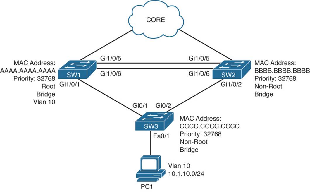
Figure 5-6 STP Trouble Ticket Topology
Trouble Ticket 5-1
Problem: Based on traffic analyzers, all traffic from the end stations in VLAN 10 destined to the core is flowing through SW2 when it should be flowing through SW1.
According to the topology, SW1 should be the root bridge for VLAN 10. Therefore, all traffic for VLAN 10 should be flowing through SW1 under normal conditions. With this in mind, check the placement of the root bridge using the show spanning-tree vlan 10 command on SW1, as shown in Example 5-15. Notice that SW1 is not the root bridge for VLAN 10. According to the root ID section of the output, the switch with the MAC address bbbb.bbbb.bbbb is the root bridge.
Example 5-15 show spanning-tree vlan 10 Command Output for SW1
SW1#show spanning-tree vlan 10
VLAN0010
Spanning tree enabled protocol ieee
Root ID Priority 10
Address bbbb.bbbb.bbbb
Cost 4
Port 5 (GigabitEthernet1/0/5)
Hello Time 2 sec Max Age 20 sec Forward Delay 15 sec
Bridge ID Priority 32778 (priority 32768 sys-id-ext 10)
Address aaaa.aaaa.aaaa
Hello Time 2 sec Max Age 20 sec Forward Delay 15 sec
Aging Time 300
Interface Role Sts Cost Prio.Nbr Type
Gi1/0/1 Desg FWD 4 128.1 P2p
Gi1/0/5 Root FWD 4 128.5 P2p
Gi1/0/6 Altn BLK 4 128.6 P2p
Next you should check which switch is the root bridge. Figure 5-6 shows that bbbb.bbbb.bbbb is the MAC of SW2. However, without the diagram, how would you figure out who the root bridge is? You would follow the path. According to the output in Example 5-15, the port on SW1 to get to the root bridge is Gigabit Ethernet 1/0/5. At the bottom of the output, you can confirm that this is the root port. Therefore, using the show cdp neighbors command, you can confirm that SW2 is directly connected to SW1 on port Gi1/0/5, as shown in Example 5-16.
Example 5-16 show cdp neighbors Command Output on SW1
SW1#show cdp neighbors
Capability Codes: R - Router, T - Trans Bridge, B - Source Route Bridge
S - Switch, H - Host, I - IGMP, r - Repeater, P - Phone,
D - Remote, C - CVTA, M - Two-port Mac Relay
Device ID Local Intrfce Holdtme Capability Platform Port ID
SW2 Gig 1/0/6 138 S I WS-C3750E Gig 1/0/6
SW2 Gig 1/0/5 138 S I WS-C3750E Gig 1/0/5
SW3 Gig 1/0/1 141 S I WS-C2960- Gig 0/1
You should now verify if SW2 is the root bridge for VLAN 10 using the output of show spanning-tree vlan 10, as shown in Example 5-17. The output shows that SW2 is the root bridge for VLAN 10. It explicitly states This bridge is the root, and notice that all the ports are designated ports.
Example 5-17 show spanning-tree vlan 10 Command Output for SW2
SW2#show spanning-tree vlan 10
VLAN0010
Spanning tree enabled protocol ieee
Root ID Priority 10
Address bbbb.bbbb.bbbb
This bridge is the root
Hello Time 2 sec Max Age 20 sec Forward Delay 15 sec
Bridge ID Priority 10 (priority 0 sys-id-ext 10)
Address bbbb.bbbb.bbbb
Hello Time 2 sec Max Age 20 sec Forward Delay 15 sec
Aging Time 300 sec
Interface Role Sts Cost Prio.Nbr Type
------------------- ---- --- --------- -------- -----------------------
Gi1/0/2 Desg FWD 4 128.2 P2p
Gi1/0/5 Desg FWD 4 128.5 P2p
Gi1/0/6 Desg FWD 4 128.6 P2p
Upon further analysis of Example 5-17, you will notice that the priority of SW2 is 0 plus the extended system ID (which is the VLAN number), for a total value of 10, which is lower than the priority of SW1, which is 32768 plus 10 (32778), as shown in Example 5-15. It appears that the priority of SW2 was manually lowered. Using the command show run | section spanning-tree indicates that the command spanning-tree vlan 10 priority 0 was executed on SW2, as shown in Example 5-18.
Example 5-18 show run Command Output for SW2
SW2#show run | section spanning-tree
...output omitted...
spanning-tree vlan 10 priority 0
...output omitted...
To solve this issue, we would need to remove this command by executing the no spanning-tree vlan 10 priority 0 command. Once done, we can verify that SW1 is now the root bridge for VLAN 10 with the show spanning-tree vlan 10 command, as shown in Example 5-19.
Example 5-19 show spanning-tree vlan 10 Command Output for SW1
SW1#show spanning-tree vlan 10
VLAN0010
Spanning tree enabled protocol ieee
Root ID Priority 32778
Address aaaa.aaaa.aaaa
This bridge is the root
Hello Time 2 sec Max Age 20 sec Forward Delay 15 sec
Bridge ID Priority 32778 (priority 32768 sys-id-ext 10)
Address aaaa.aaaa.aaaa
Hello Time 2 sec Max Age 20 sec Forward Delay 15 sec
Aging Time 300 sec
Interface Role Sts Cost Prio.Nbr Type
------------------- ---- --- --------- -------- -----------------------
Gi1/0/1 Desg FWD 4 128.1 P2p
Gi1/0/5 Desg FWD 4 128.5 P2p
Gi1/0/6 Desg FWD 4 128.6 P2p
Trouble Ticket 5-2
Problem: Based on traffic analyzers, all traffic from the end stations in VLAN 10 destined to the core is flowing through SW2 when it should be flowing through SW1.
According to the topology, SW1 should be the root bridge for VLAN 10. Therefore, all traffic for VLAN 10 should be flowing through SW1 under normal conditions. With this in mind, check the placement of the root bridge using the show spanning-tree vlan 10 command on SW1, as shown in Example 5-20. Notice that SW1 is the root bridge for VLAN 10.
Example 5-20 show spanning-tree vlan 10 Command Output for SW1
SW1#show spanning-tree vlan 10
VLAN0010
Spanning tree enabled protocol ieee
Root ID Priority 32778
Address aaaa.aaaa.aaaa
This bridge is the root
Hello Time 2 sec Max Age 20 sec Forward Delay 15 sec
Bridge ID Priority 32778 (priority 32768 sys-id-ext 10)
Address aaaa.aaaa.aaaa
Hello Time 2 sec Max Age 20 sec Forward Delay 15 sec
Aging Time 300 sec
Interface Role Sts Cost Prio.Nbr Type
------------------- ---- --- --------- -------- -----------------------
Gi1/0/1 Desg FWD 4 128.1 P2p
Gi1/0/5 Desg FWD 4 128.5 P2p
Gi1/0/6 Desg FWD 4 128.6 P2p
We have confirmed that SW1 is the root bridge and this matches our diagram in Figure 5-6. If Figure 5-6 has been kept up to date, we can trust the information displayed. According to Figure 5-6, we have a Gigabit Ethernet link between SW3 and SW1 as well as SW3 and SW2. These links should have a cost of 4 by default. Reviewing the output of show spanning-tree vlan 10 on SW3, we can see that to reach the root bridge the total cost is 8 using Gigabit Ethernet 0/2, as shown in Example 5-21. If we look at Gig0/1, it is currently an alternate port in the blocking state with a cost of 10. This cost of 10 is larger than the total cost of 8 using Gig0/2. It appears that the cost of interface Gig0/1 has been modified.
Example 5-21 show spanning-tree vlan 10 Command Output for SW3
SW3#show spanning-tree vlan 10
VLAN0010
Spanning tree enabled protocol ieee
Root ID Priority 32778
Address aaaa.aaaa.aaaa
Cost 8
Port 2 (GigabitEthernet0/2)
Hello Time 2 sec Max Age 20 sec Forward Delay 15 sec
Bridge ID Priority 32778 (priority 32768 sys-id-ext 10)
Address cccc.cccc.cccc
Hello Time 2 sec Max Age 20 sec Forward Delay 15 sec
Aging Time 300 sec
Interface Role Sts Cost Prio.Nbr Type
------------------- ---- --- --------- -------- -----------------------
Gi0/1 Altn BLK 10 128.1 P2p
Gi0/2 Root FWD 4 128.2 P2p
The output of show run interface gig 0/1 confirms that the cost was modified with the spanning-tree vlan 10 cost 10 command, as shown in Example 5-22. To solve this issue, we need to execute the no spanning-tree vlan 10 cost 10 command in interface configuration mode.
Example 5-22 show run interface gig 0/1 Command Output for SW3
SW3#show run interface gig 0/1
...output omitted...
spanning-tree vlan 10 cost 10
...output omitted...
After we remove the command, we can verify that SW3 is using Gi0/1 as the root port and that it has a cost of 4 by issuing the show spanning-tree vlan 10 command shown in Example 5-23.
Example 5-23 show spanning-tree vlan 10 Command Output for SW3
SW3#show spanning-tree vlan 10
VLAN0010
Spanning tree enabled protocol ieee
Root ID Priority 32778
Address aaaa.aaaa.aaaa
Cost 4
Port 1 (GigabitEthernet0/1)
Hello Time 2 sec Max Age 20 sec Forward Delay 15 sec
Bridge ID Priority 32778 (priority 32768 sys-id-ext 10)
Address cccc.cccc.cccc
Hello Time 2 sec Max Age 20 sec Forward Delay 15 sec
Aging Time 300 sec
Interface Role Sts Cost Prio.Nbr Type
------------------- ---- --- --------- -------- -----------------------
Gi0/1 Root FWD 4 128.1 P2p
Gi0/2 Altn BLK 4 128.2 P2p
Trouble Ticket 5-3
Problem: It is Tuesday morning, and a user has indicated that he cannot connect to the network. He also indicates that he had no issues on Monday when he left work at 5:45 p.m.
You attempt to ping from the user’s PC to its default gateway, but it fails. You attempt to ping from the user’s PC to the Internet, but it fails. Your next task is to make sure that the PC is receiving an IP address from the Dynamic Host Configuration Protocol (DHCP) server in the network. Issuing the command ipconfig /all on the PC as depicted in Example 5-24 indicates that an Automatic Private IP Addressing (APIPA) address (169.254.x.x/16) is being used by the PC. Therefore, they are not able to contact a DHCP server. Also note the MAC address of PC1 at this point, as it will be useful later.
Example 5-24 ipconfig Output for PC
PC1>ipconfig /all
Windows Ip Configuration
<Output Omitted>
Ethernet adapter Local Area Connection:
<Output Omitted>
Physical Address. . . . . . . . . : 08-00-27-5D-06-D6
Link-local IPv6 Address . . . . . : fe80::444c:23b1:6e1e:de0c%16
Dhcp enabled. . . . . . . . . . . : Yes
Autoconfiguration enabled. . .. . : Yes
Autoconfiguration IP Address. . . : 169.254.180.166
Subnet Mask . . . . . . . . . . . : 255.255.0.0
<Output Omitted>
Issuing the command show mac address-table dynamic on SW3 will indicate whether SW3 is receiving any frames from PC1. Example 5-25 is displaying the MAC address table of SW3, and there is no entry in the table with PC1’s MAC address. Therefore, something appears to be wrong at Layer 1 or Layer 2 of the OSI model.
Example 5-25 show mac address-table dynamic Output for SW3
SW3#show mac address-table dynamic
Mac Address Table
---- -------------------------------- --------- -------------------------------
Vlan Mac Address Type Ports
---- ----------- -------- -----
10 0800.275d.1234 DYNAMIC Gi0/1
10 0800.275d.ac47 DYNAMIC Fa0/4
10 0800.275d.b3dd DYNAMIC Fa0/3
10 0800.275d.ce47 DYNAMIC Fa0/2
10 0800.275d.ed13 DYNAMIC Gi0/1
Total Mac Addresses for this criterion: 6
You verify physical connectivity and everything is perfect. However, you notice that the LED of the switchport PC1 is connected to is amber rather than green, confirming that something is not right. According to Figure 5-6, PC1 should be in VLAN 10. Issuing the command show vlan briefwill confirm this for us. Example 5-26 shows that interface Fa0/1, which is connected to PC1, is in VLAN 10. In addition, the output of show interfaces status | include Fa0/1, as shown in Example 5-27, does not indicate that anything is wrong.
Example 5-26 show vlan brief Output for SW3
SW3#show vlan brief
VLAN Name Status Ports
---- -------------------------------- --------- -------------------------------
1 default active Fa0/5, Fa0/6, Fa0/7, Fa0/8,
Fa0/9, Fa0/10, Fa0/11, Fa0/12,
Fa0/13, Fa0/14, Fa0/15, Fa0/16,
Fa0/17, Fa0/18, Fa0/19, Fa0/20,
Fa0/21, Fa0/22, Fa0/23, Fa0/24,
10 10.1.10.0/24 active Fa0/1, Fa0/2, Fa0/3, Fa0/4,
20 10.1.20.0/24 active
1002 fddi-default act/unsup
1003 trcrf-default act/unsup
1004 fddinet-default act/unsup
1005 trbrf-default act/unsup
Example 5-27 show interfaces status | include Fa0/1 Output for SW3
SW3#show interfaces status | include Fa0/1
Port Name Status Vlan Duplex Speed Type
Fa0/1 connected 10 a-full a-10010/100BaseTX
No other users at this point have indicated that they are experiencing issues. You decide to check the SW3 logs on your syslog server and notice the following entry:
%SPANTREE-2-ROOTGUARD_BLOCK: Root guard blocking port FastEthernet0/1 on
VLAN0010.
It appears that BPDUs are being received by Fast Ethernet 0/1 from PC1. Issuing the command show spanning-tree inconsistentports on SW3 confirms that Fast Ethernet 0/1 is in the root-inconsistent state, as shown in Example 5-28.
Example 5-28 show spanning-tree inconsistentports Output for SW3
SW3#show spanning-tree inconsistentports
Name Interface Inconsistency
-------------------- ---------------------- ------------------
VLAN0010 FastEthernet0/1 Root Inconsistent
Number of inconsistent ports (segments) in the system : 1
Upon further examination, beyond the scope of this book, an application was installed on PC1 after hours that mimics a switch and sends BPDUs. Further investigation will be needed to determine whether this was malicious or by accident.
To solve this issue, we remove the offending application from PC1, and the switch will recover the port automatically, as shown in Example 5-29.
Example 5-29 SW3 show spanning-tree inconsistenetports Output After Application Removed from PC1
SW3#
%SPANTREE-2-ROOTGUARD_UNBLOCK: Root guard unblocking port FastEthernet0/1 on
VLAN0010.
SW3#show spanning-tree inconsistentports
Name Interface Inconsistency
-------------------- ---------------------- ------------------
Number of inconsistent ports (segments) in the system : 0
The output of ipconfig on PC1 in Example 5-30 verifies it has an IP address and a ping to 10.1.10.1, PC1’s default gateway, is successful.
Example 5-30 ipconfig and ping Output for PC After Issue Solved
PC1>ipconfig
Windows IP Configuration
Ethernet adapter Local Area Connection:
Connection-specific DNS Suffix . : domain.local
Link-local IPv6 Address . . . . . : fe80::444c:23b1:6e1e:de0c%16
IPv4 Address. . . . . . . . . . . : 10.1.10.10
Subnet Mask . . . . . . . . . . . : 255.255.255.0
Default Gateway . . . . . . . . . : 10.1.10.1
PC1>ping 10.1.10.1
Pinging 10.1.1.1 with 32 bytes of data:
Reply from 10.1.10.1: bytes=32 time<1ms TTL=255
Reply from 10.1.10.1: bytes=32 time=1ms TTL=255
Reply from 10.1.10.1: bytes=32 time=3ms TTL=255
Reply from 10.1.10.1: bytes=32 time=1ms TTL=255
Ping statistics for 10.1.10.1:
Packets: Sent = 4, Received = 4, Lost = 0 (0% loss),
Approximate round trip times in milli-seconds:
Minimum = 0ms, Maximum = 3ms, Average = 1ms
Troubleshooting Layer 2 EtherChannel
An exception to STP operation can be made if two switches are interconnected via multiple physical links and those links are configured as an EtherChannel. An EtherChannel logically combines the bandwidth of multiple physical interfaces into a logical connection between switches, as illustrated in Figure 5-7. Specifically, Figure 5-7 shows four Gigabit Ethernet links logically bonded into a single EtherChannel link.
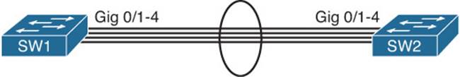
Figure 5-7 Layer 2 EtherChannel
This section reviews what is necessary to successfully form a Layer 2 EtherChannel bundle and the EtherChannel mode combinations that will successfully form the bundle.
Reviewing Layer 2 EtherChannel
When multiple ports are combined into a logical EtherChannel, STP treats the logical bundle (known as a port channel) as a single port for STP calculation purposes. Following are common troubleshooting targets to consider when troubleshooting an EtherChannel issue:
![]() Mismatched port configurations: The configurations of all ports making up an EtherChannel, on both switches, should be identical. For example, all ports should have the same speed, duplex, trunk mode, native VLAN configurations, allowed VLAN configurations, and port type (Layer 2 or Layer 3).
Mismatched port configurations: The configurations of all ports making up an EtherChannel, on both switches, should be identical. For example, all ports should have the same speed, duplex, trunk mode, native VLAN configurations, allowed VLAN configurations, and port type (Layer 2 or Layer 3).
![]() Mismatched EtherChannel configuration: Both switches forming the EtherChannel should be configured with compatible modes. There are three options, Link Aggregation Control Protocol (LACP), Port Aggregation Protocol (PAgP), and ON. These modes are not compatible with each other. In addition, when using LACP or PAgP, you have to make sure that the modes within the protocol can successfully form the bundle with each other. Table 5-4 identifies which modes can be configured on each switch to successfully form an EtherChannel bundle.
Mismatched EtherChannel configuration: Both switches forming the EtherChannel should be configured with compatible modes. There are three options, Link Aggregation Control Protocol (LACP), Port Aggregation Protocol (PAgP), and ON. These modes are not compatible with each other. In addition, when using LACP or PAgP, you have to make sure that the modes within the protocol can successfully form the bundle with each other. Table 5-4 identifies which modes can be configured on each switch to successfully form an EtherChannel bundle.
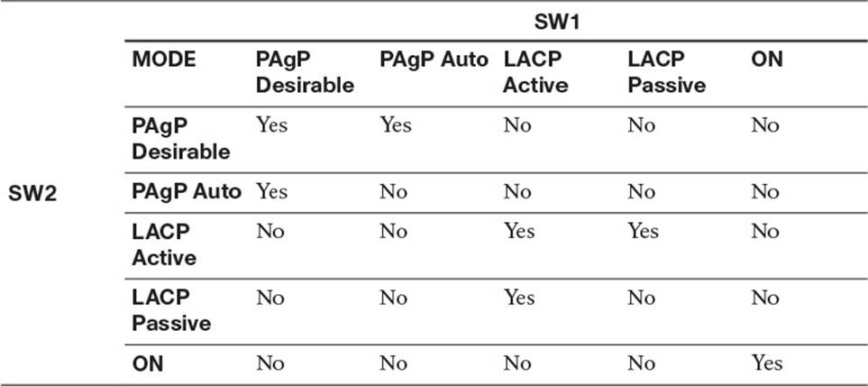
Table 5-4 EtherChannel Modes That Will Successfully Form a Bundle
![]() Inappropriate EtherChannel distribution algorithm: EtherChannel determines which physical link to use to transmit frames based on a hash calculation. The hashing approach selected should distribute the load fairly evenly across all physical links. For example, a hash calculation might be based only on the destination MAC address of a frame. If the frames are destined for only a few different MAC addresses, the load distribution could be uneven. To verify the load-balancing algorithm in use, issue the show etherchannel load-balance command.
Inappropriate EtherChannel distribution algorithm: EtherChannel determines which physical link to use to transmit frames based on a hash calculation. The hashing approach selected should distribute the load fairly evenly across all physical links. For example, a hash calculation might be based only on the destination MAC address of a frame. If the frames are destined for only a few different MAC addresses, the load distribution could be uneven. To verify the load-balancing algorithm in use, issue the show etherchannel load-balance command.
EtherChannel Trouble Tickets
This section presents various trouble tickets relating to the topics discussed earlier in the chapter. The purpose of these trouble tickets is to give a process that you can follow when troubleshooting in the real world or in an exam environment. All trouble tickets in this section are based on the topology depicted in Figure 5-8.
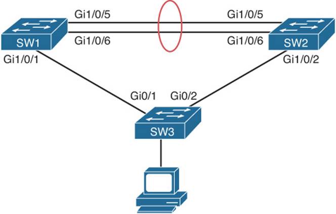
Figure 5-8 Layer 2 EtherChannel Trouble Ticket Topology
Trouble Ticket 5-4
Problem: A junior network administrator has approached you indicating that the EtherChannel bundle she is trying to form between SW1 and SW2 is not forming. You need to solve this issue for her.
You start by reviewing the output of show etherchannel summary for SW1 and SW2, as shown in Example 5-31. Notice that both switches are using LACP as their protocol; however, the ports are either standalone or suspended, and the port channel is down. This is a good indication that there is a conflict with the port configurations.
Example 5-31 show etherchannel summary Output for SW1 and SW2
SW1#show etherchannel summary
Flags: D - down P - bundled in port-channel
I - stand-alone s - suspended
H - Hot-standby (LACP only)
R - Layer3 S - Layer2
U - in use f - failed to allocate aggregator
M - not in use, minimum links not met
u - unsuitable for bundling
w - waiting to be aggregated
d - default port
Number of channel-groups in use: 1
Number of aggregators: 1
Group Port-channel Protocol Ports
------+-------------+-----------+--------------------------------------
1 Po1(SD) LACP Gi1/0/5(I) Gi1/0/6(s)
SW2#show etherchannel summary
Flags: D - down P - bundled in port-channel
I - stand-alone s - suspended
H - Hot-standby (LACP only)
R - Layer3 S - Layer2
U - in use f - failed to allocate aggregator
M - not in use, minimum links not met
u - unsuitable for bundling
w - waiting to be aggregated
d - default port
Number of channel-groups in use: 1
Number of aggregators: 1
Group Port-channel Protocol Ports
------+-------------+-----------+--------------------------------------
1 Po1(SD) LACP Gi1/0/5(I) Gi1/0/6(I)
To verify the port configuration you issue the show run interface gigabitethernet 1/0/5 and show run interface gigabitethernet 1/0/6 command on SW1 and SW2, as shown in Example 5-32. If you look closely, you will notice that the switchport modes do not match on the SW1 interfaces that are part of the EtherChannel bundle. To form the bundle, they have to match.
Example 5-32 show run interface gigabitethernet Output for SW1 and SW2
SW1#show run interface gigabitethernet 1/0/5
Building configuration...
Current configuration : 189 bytes
!
interface GigabitEthernet1/0/5
switchport trunk encapsulation isl
switchport mode access
switchport nonegotiate
channel-group 1 mode active
end
SW1#show run interface gigabitethernet 1/0/6
Building configuration...
Current configuration : 189 bytes
!
interface GigabitEthernet1/0/6
switchport trunk encapsulation isl
switchport mode trunk
switchport nonegotiate
channel-group 1 mode active
end
SW2#show run interface gigabitethernet 1/0/5
Building configuration...
Current configuration : 151 bytes
!
interface GigabitEthernet1/0/5
switchport trunk encapsulation isl
switchport mode trunk
switchport nonegotiate
channel-group 1 mode passive
end
SW2#show run interface gigabitethernet 1/0/6
Building configuration...
Current configuration : 151 bytes
!
interface GigabitEthernet1/0/6
switchport trunk encapsulation isl
switchport mode trunk
switchport nonegotiate
channel-group 1 mode passive
end
Once you change the switchport mode on SW1 Gigabit Ethernet 1/0/5 with the switchport mode trunk command, the port channel interface should come up, as shown with the following logging messages:
%LINK-3-UPDOWN: Interface Port-channel1, changed state to up
%LINEPROTO-5-UPDOWN: Line protocol on Interface Port-channel1, changed state to up
In addition, the EtherChannel bundle should now be successfully formed. Reviewing the output of show etherchannel summary on SW1 and SW2 indicates that the ports are successfully bundled with the (P) flags and that the port channel is in use with the (U) flag, as shown in Example 5-33.
Example 5-33 show etherchannel summary Output for SW1 and SW2 After Problem Solved
SW1#show etherchannel summary
Flags: D - down P - bundled in port-channel
I - stand-alone s - suspended
H - Hot-standby (LACP only)
R - Layer3 S - Layer2
U - in use f - failed to allocate aggregator
M - not in use, minimum links not met
u - unsuitable for bundling
w - waiting to be aggregated
d - default port
Number of channel-groups in use: 1
Number of aggregators: 1
Group Port-channel Protocol Ports
------+-------------+-----------+--------------------------------------
1 Po1(SU) LACP Gi1/0/5(P) Gi1/0/6(P)
SW2#show etherchannel summary
Flags: D - down P - bundled in port-channel
I - stand-alone s - suspended
H - Hot-standby (LACP only)
R - Layer3 S - Layer2
U - in use f - failed to allocate aggregator
M - not in use, minimum links not met
u - unsuitable for bundling
w - waiting to be aggregated
d - default port
Number of channel-groups in use: 1
Number of aggregators: 1
Group Port-channel Protocol Ports
------+-------------+-----------+--------------------------------------
1 Po1(SU) LACP Gi1/0/5(P) Gi1/0/6(P)
Trouble Ticket 5-5
Problem: A junior network administrator has approached you indicating that the EtherChannel bundle he is trying to form between SW1 and SW2 is not forming. You need to solve this issue for him.
You start by checking whether the port channel is up on SW1 and SW2, as shown in Example 5-34. According to the output, it is down/down.
Example 5-34 show ip interface brief | include Port Output for SW1 and SW2
SW1#show ip interface brief | include Port
Port-channel1 unassigned YES unset down down
SW2#show ip interface brief | include Port
Port-channel1 unassigned YES unset down down
Next you check the status of the EtherChannel bundle with the show etherchannel summary command, as shown in Example 5-35. Notice that the port channel is down and that all interfaces are standalone. However, if you look closer, you will see the issue. SW1 is using PAgP, and SW2 is using LACP. These EtherChannel protocols are not compatible. Therefore, to solve this issue, you will need to verify your documentation to determine which protocol should be used between SW1 and SW2 and make the appropriate adjustments.
Example 5-35 show etherchannel summary Output for SW1 and SW2
SW1#show etherchannel summary
Flags: D - down P - bundled in port-channel
I - stand-alone s - suspended
H - Hot-standby (LACP only)
R - Layer3 S - Layer2
U - in use f - failed to allocate aggregator
M - not in use, minimum links not met
u - unsuitable for bundling
w - waiting to be aggregated
d - default port
Number of channel-groups in use: 1
Number of aggregators: 1
Group Port-channel Protocol Ports
------+-------------+-----------+--------------------------------------
1 Po1(SD) PAgP Gi1/0/5(I) Gi1/0/6(I)
SW2#show etherchannel summary
Flags: D - down P - bundled in port-channel
I - stand-alone s - suspended
H - Hot-standby (LACP only)
R - Layer3 S - Layer2
U - in use f - failed to allocate aggregator
M - not in use, minimum links not met
u - unsuitable for bundling
w - waiting to be aggregated
d - default port
Number of channel-groups in use: 1
Number of aggregators: 1
Group Port-channel Protocol Ports
------+-------------+-----------+--------------------------------------
1 Po1(SD) LACP Gi1/0/5(I) Gi1/0/6(I)
Exam Preparation Tasks
As mentioned in the section “How to Use This Book” in the Introduction, you have a couple of choices for exam preparation: the exercises here; Chapter 22, “Final Preparation;” and the exam simulation questions on the CD-ROM.
Review All Key Topics
Review the most important topics in this chapter, noted with the Key Topic icon in the outer margin of the page. Table 5-5 lists a reference of these key topics and the page numbers on which each is found.
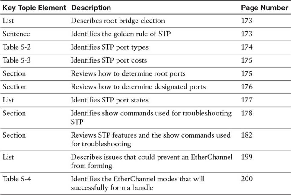
Table 5-5 Key Topics for Chapter 5
Define Key Terms
Define the following key terms from this chapter and check your answers in the glossary:
Spanning Tree Protocol (STP)
root bridge
root port
designated port
nondesignated port
blocking
listening
learning
forwarding
802.1D
802.1w
802.1s
Layer 2 EtherChannel
PAgP
LACP
Complete Tables and Lists from Memory
Print a copy of Appendix C, “Memory Tables,” (found on the disc), or at least the section for this chapter, and complete the tables and lists from memory. Appendix D, “Memory Tables Answer Key,” also on the disc, includes completed tables and lists to check your work.
Command Reference to Check Your Memory
This section includes the show commands introduced in this chapter. It does not include the show commands that were used in this chapter but introduced in previous chapters. You will need to return to the previous chapters to review information relating to those show commands.
To test your memory of the commands, cover the right side of Table 5-6 with a piece of paper, read the description on the left side, and then see how much of the command you can remember.
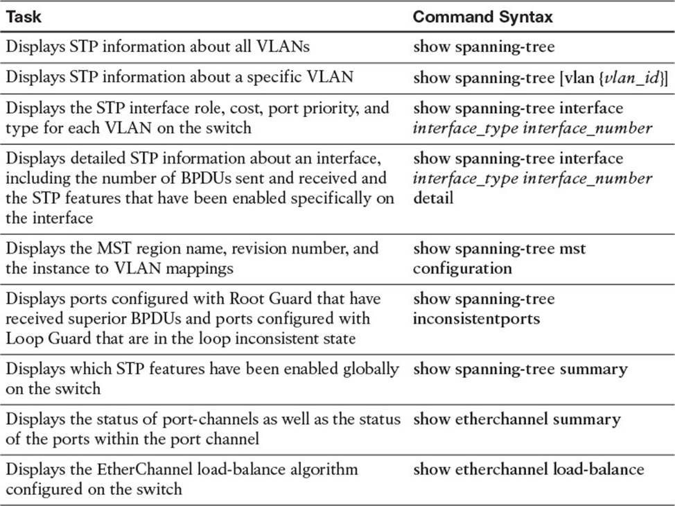
Table 5-6 show Commands Introduced in Chapter 5
The 300-135 TSHOOT exam focuses on practical, hands-on skills that are used by a networking professional. Therefore, you should be able to identify the show commands needed to successfully troubleshoot the topics covered in this chapter.
All materials on the site are licensed Creative Commons Attribution-Sharealike 3.0 Unported CC BY-SA 3.0 & GNU Free Documentation License (GFDL)
If you are the copyright holder of any material contained on our site and intend to remove it, please contact our site administrator for approval.
© 2016-2026 All site design rights belong to S.Y.A.