CCNP Routing and Switching TSHOOT 300-135 Official Cert Guide (2015)
Part II. Troubleshooting Cisco Catalyst Switch Features
Chapter 6. Troubleshooting Inter-VLAN Routing and Layer 3 EtherChannels
This chapter covers the following topics:
![]() Troubleshooting a Router-on-a-Trunk/Stick: This section covers how to troubleshoot inter-VLAN routing issues when using the router-on-a-trunk scenario.
Troubleshooting a Router-on-a-Trunk/Stick: This section covers how to troubleshoot inter-VLAN routing issues when using the router-on-a-trunk scenario.
![]() Router-on-a-Trunk/Stick Trouble Tickets: This section provides trouble tickets that demonstrate how you can use a structured troubleshooting process to solve a reported problem.
Router-on-a-Trunk/Stick Trouble Tickets: This section provides trouble tickets that demonstrate how you can use a structured troubleshooting process to solve a reported problem.
![]() Troubleshooting Switched Virtual Interfaces: This section identifies what is necessary for an SVI to be up/up and provide inter-VLAN routing. You will also learn how to troubleshoot issues related to SVIs.
Troubleshooting Switched Virtual Interfaces: This section identifies what is necessary for an SVI to be up/up and provide inter-VLAN routing. You will also learn how to troubleshoot issues related to SVIs.
![]() SVI Trouble Tickets: This section provides trouble tickets that demonstrate how you can use a structured troubleshooting process to solve a reported problem.
SVI Trouble Tickets: This section provides trouble tickets that demonstrate how you can use a structured troubleshooting process to solve a reported problem.
![]() Troubleshooting Routed Ports: This section reviews what is necessary to convert a Layer 2 switchport into a routed port.
Troubleshooting Routed Ports: This section reviews what is necessary to convert a Layer 2 switchport into a routed port.
![]() Routed Port Trouble Tickets: This section provides trouble tickets that demonstrate how you can use a structured troubleshooting process to solve a reported problem.
Routed Port Trouble Tickets: This section provides trouble tickets that demonstrate how you can use a structured troubleshooting process to solve a reported problem.
![]() Troubleshooting Layer 3 EtherChannel: This section focuses on the steps needed to successfully troubleshoot a Layer 3 EtherChannel that relies on routed ports.
Troubleshooting Layer 3 EtherChannel: This section focuses on the steps needed to successfully troubleshoot a Layer 3 EtherChannel that relies on routed ports.
![]() Layer 3 EtherChannel Trouble Tickets: This section provides trouble tickets that demonstrate how you can use a structured troubleshooting process to solve a reported problem.
Layer 3 EtherChannel Trouble Tickets: This section provides trouble tickets that demonstrate how you can use a structured troubleshooting process to solve a reported problem.
Chapters 4, “Troubleshooting Layer 2 Trunks, VTP, and VLANs,” and 5, “Troubleshooting STP and Layer 2 EtherChannel,” focused on Cisco Catalyst switches as Layer 2 switches. These switches operate at Layer 2 of the OSI model, forwarding or flooding frames based on the MAC addresses in the frame. However, many Cisco Catalyst switches are Layer 3 switches. These Layer 3 switches can perform both Layer 2 and Layer 3 services.
Of the Layer 3 services, routing is the most common that is implemented. Through the use of virtual Layer 3 interfaces (known as switched virtual interfaces [SVIs]) or by converting a Layer 2 switchport to a routed port, you can assign IP addresses to these interfaces and have the Layer 3 switch route data between VLANs and subnets. In addition, you can use routed ports to create Layer 3 EtherChannels.
This chapter focuses on how you can troubleshoot different inter-VLAN routing implementations, routed ports, and Layer 3 EtherChannel. You will also be exposed to a few different troubleshooting scenarios for each.
“Do I Know This Already?” Quiz
The “Do I Know This Already?” quiz allows you to assess whether you should read this entire chapter thoroughly or jump to the “Exam Preparation Tasks” section. If you are in doubt about your answers to these questions or your own assessment of your knowledge of the topics, read the entire chapter. Table 6-1 lists the major headings in this chapter and their corresponding “Do I Know This Already?” quiz questions. You can find the answers in Appendix A, “Answers to the ‘Do I Know This Already?’ Quizzes.”
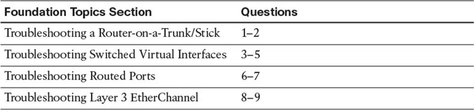
Table 6-1 “Do I Know This Already?” Section-to-Question Mapping
Caution
The goal of self-assessment is to gauge your mastery of the topics in this chapter. If you do not know the answer to a question or are only partially sure of the answer, you should mark that question as wrong for purposes of the self-assessment. Giving yourself credit for an answer that you correctly guess skews your self-assessment results and might provide you with a false sense of security.
1. Which command enables you to associate a VLAN with a router subinterface?
a. encapsulation
b. interface
c. ip address
d. vlan
2. Which show command enables you to verify the VLAN that has been associated with a router subinterface?
a. show interface trunk
b. show vlan brief
c. show ip route
d. show vlans
3. What must be true for an SVI to be up/up? (Choose two answers.)
a. The VLAN associated with the SVI must exist on the switch.
b. The SVI must be disabled.
c. There must be at least one interface on the switch associated with the VLAN in the spanning-tree forwarding state.
d. IP routing must be enabled on the switch.
4. Which show command enables you to verify the status of the SVI for VLAN 10 and the MAC address associated with it?
a. show ip interface brief
b. show interfaces vlan 10
c. show ip interface vlan 10
d. show svi
5. Which command enables IPv4 unicast routing on a Layer 3 switch?
a. routing
b. ip route
c. ip routing
d. ip unicast-routing
6. Which command enables you to convert a Layer 2 switchport to a routed port?
a. no switchport
b. routed port
c. ip address
d. ip routing
7. Which show command enables you to verify whether interface Gigabit Ethernet 1/0/10 is a Layer 2 switchport or a routed port?
a. show gigabitethernet 1/0/10 switchport
b. show interfaces gigabitethernet 1/0/10
c. show interfaces gigabitethernet 1/0/10 switchport
d. show interfaces status
8. What flags in the show etherchannel summary output indicate that the EtherChannel is Layer 3 and in use?
a. SU
b. SD
c. RU
d. RD
9. Which EtherChannel modes will successfully form an LACP EtherChannel?
a. Active-auto
b. Desirable-auto
c. Passive-desirable
d. Active-passive
10. Which EtherChannel flag indicates that the port is bundled in the EtherChannel bundle?
a. R
b. S
c. P
d. H
Foundation Topics
Troubleshooting a Router-on-a-Trunk/Stick
For traffic to pass from one VLAN to another VLAN, it has to be routed. This is easy to remember if you recall that a VLAN = a subnet and to send traffic from one subnet to another you route it. Therefore, to send traffic from one VLAN to another VLAN, you also route it.
This section reviews how you can use an external router that is trunked to a switch to perform routing between VLANs. The section also covers the various issues that could cause this implementation to not function as expected.
Before Layer 3 switches existed, we relied on external routers to perform inter-VLAN routing. The external router was connected to the Layer 2 switch via a trunk, which created the router-on-a-stick or router-on-a-trunk topology, as shown in Figure 6-1.
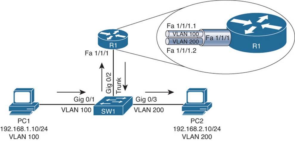
Figure 6-1 Router-on-a-Trunk / Router-on-a-Stick
In Figure 6-1, router R1’s Fast Ethernet 1/1/1 interface has two subinterfaces as indicated by the period (.) in the interface identification. There is one for each VLAN, Fast Ethernet 1/1/1.1 for VLAN 100 and Fast Ethernet 1/1/1.2 for VLAN 200. Router R1 can route between VLANs 100 and 200, while simultaneously receiving and transmitting traffic over the trunk connection to the switch. Review Example 6-1 and Example 6-2, which outline the configurations needed to implement a router-on-a-trunk.

Example 6-1 show run Command Output from R1
R1#show run
...output omitted...
interface FastEthernet1/1/1.1
encapsulation dot1Q 100
ip address 192.168.1.1 255.255.255.0
!
interface FastEthernet1/1/1.2
encapsulation dot1Q 200
ip address 192.168.2.1 255.255.255.0
...output omitted...
Example 6-2 show run Command Output from SW1
SW1#show run
...output omitted...
interface GigabitEthernet0/1
switchport mode access
switchport access vlan 100
interface GigabitEthernet0/2
switchport trunk encapsulation dot1q
switchport mode trunk
switchport nonegotiate
interface GigabitEthernet0/3
switchport mode access
switchport access vlan 200
...output omitted...
After reviewing Example 6-1 and Example 6-2, what are issues that could prevent inter-VLAN routing from being successful?
![]() Trunk encapsulation mismatch
Trunk encapsulation mismatch
![]() Incorrect VLAN assignment on routers’ subinterfaces
Incorrect VLAN assignment on routers’ subinterfaces
![]() Incorrect IP address or subnet mask on routers’ subinterfaces
Incorrect IP address or subnet mask on routers’ subinterfaces
![]() Incorrect IP address, subnet mask, or default gateway on PCs
Incorrect IP address, subnet mask, or default gateway on PCs
![]() Switchport connected to router configured as an access port
Switchport connected to router configured as an access port
![]() Switchport connected to router configured to use Dynamic Trunking Protocol (DTP), which is not supported by the router
Switchport connected to router configured to use Dynamic Trunking Protocol (DTP), which is not supported by the router
![]() Switchports connected to PCs in wrong VLAN
Switchports connected to PCs in wrong VLAN
Being able to identify these issues and correct them is important for any troubleshooter.
Router-on-a-Trunk/Stick Trouble Tickets
This section covers various trouble tickets relating to the topics discussed earlier in the chapter. The purpose of these trouble tickets is to give a process that you can follow when troubleshooting in the real world or in an exam environment. All trouble tickets in this section are based on the topology depicted in Figure 6-2.
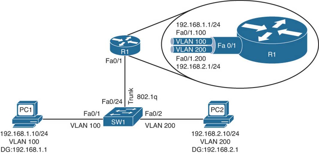
Figure 6-2 Router-on-a-Trunk Trouble Tickets
Trouble Ticket 6-1
Problem: PC1 is not able to access resources on PC2.
As you dive deeper into trouble tickets, everything covered in the previous chapters still applies because the PCs are still connected to the switches, there are still VLANs, and there are trunks. As a result, having a repeatable structured troubleshooting process in place will help you maintain focus and clarity as you troubleshoot.
The first item on the list of troubleshooting is to verify the problem. Issuing the ping command on PC1, as shown in Example 6-3, indicates that PC1 is not able to reach PC2, confirming the problem.
Example 6-3 Failed Ping from PC1 to PC2
C:\PC1>ping 192.168.2.10
Pinging 192.168.2.10 with 32 bytes of data:
Request timed out.
Request timed out.
Request timed out.
Request timed out.
Ping statistics for 192.168.2.10:
Packets: Sent = 4, Received = 0, Lost = 4 (100% loss),
Next you need to verify whether PC1 can get to its default gateway. This will help you narrow down where the issue may be. Pinging PC1s default gateway, as shown in Example 6-4, is not successful. This indicates that we have an issue between PC1 and the default gateway.
Example 6-4 Failed Ping from PC1 to Default Gateway
C:\PC1>ping 192.168.1.1
Pinging 192.168.1.1 with 32 bytes of data:
Request timed out.
Request timed out.
Request timed out.
Request timed out.
Ping statistics for 192.168.1.1:
Packets: Sent = 4, Received = 0, Lost = 4 (100% loss),
Now is an excellent time to brainstorm the likely causes of the issue based on Figure 6-2 and the fact that PC1 is not able to ping its default gateway:
![]() PC1 may have an incorrect IP address, subnet mask, or default gateway configured.
PC1 may have an incorrect IP address, subnet mask, or default gateway configured.
![]() SW1 switchport FA0/1 may not be associated with the correct VLAN.
SW1 switchport FA0/1 may not be associated with the correct VLAN.
![]() VLAN 100 may not exist on SW1.
VLAN 100 may not exist on SW1.
![]() PC1 may physically be connected to the wrong switchport.
PC1 may physically be connected to the wrong switchport.
![]() SW1 Fa0/24 may not be configured as a trunk.
SW1 Fa0/24 may not be configured as a trunk.
![]() SW1 Fa0/24 may not be allowing VLAN 100 traffic on the trunk.
SW1 Fa0/24 may not be allowing VLAN 100 traffic on the trunk.
![]() SW1 Fa0/24 may be using the wrong trunk encapsulation.
SW1 Fa0/24 may be using the wrong trunk encapsulation.
![]() R1 may not have the appropriate subinterfaces configured with the correct IP addresses or subnet masks.
R1 may not have the appropriate subinterfaces configured with the correct IP addresses or subnet masks.
![]() R1’s subinterfaces may be using the wrong trunk encapsulation.
R1’s subinterfaces may be using the wrong trunk encapsulation.
![]() R1’s subinterfaces may be disabled.
R1’s subinterfaces may be disabled.
As you can see, the list is quite extensive, and it is not even a complete list. Let’s start following the path from PC1 and work toward the router. Issuing ipconfig on PC1 indicates that it has the correct IP address, subnet mask, and default gateway configured, as shown in Example 6-5, when compared to Figure 6-2.
Example 6-5 ipconfig Output on PC1
C:\PC1>ipconfig
Windows IP Configuration
Ethernet adapter Local Area Connection:
Connection-specific DNS Suffix . :
IP Address. . . . . . . . . . . . : 192.168.1.10
Subnet Mask . . . . . . . . . . . : 255.255.255.0
Default Gateway . . . . . . . . . : 192.168.1.1
Issuing the show mac address-table dynamic command on SW1 will identify which MAC address is being learned on Fa0/1 and which VLAN it is associated with. Example 6-6 is indicating that the MAC address of 0800.275d.06d6 is being learned on Fa0/1 and that it is associated with VLAN 100. Issuing the ipconfig /all command on PC1, as shown in Example 6-7, identifies PC1’s MAC as 0800.275d.06d6, which is the same as the one outlined in the MAC address table. We can narrow our focus now because this proves that PC1 is connected to the correct switchport, VLAN 100 exists, and Fa0/1 is in the correct VLAN.
Example 6-6 show mac address-table dynamic Command Output on SW1
SW1#show mac address-table dynamic
Mac Address Table
-------------------------------------------
Vlan Mac Address Type Ports
---- ----------- -------- -----
100 0800.275d.06d6 DYNAMIC Fa0/1
200 0800.27a2.ce47 DYNAMIC Fa0/2
Total Mac Addresses for this criterion: 2
Example 6-7 ipconfig /all Output on PC1
C:\PC1>ipconfig
...output omitted...
Ethernet adapter Local Area Connection:
Connection-specific DNS Suffix . :
Description . . . . . . . . . . . : AMD PCNET Family PCI Ethernet Adapter
Physical Address. . . . . . . . . : 08-00-27-5D-06-D6
Dhcp Enabled. . . . . . . . . . . : No
IP Address. . . . . . . . . . . . : 192.168.1.10
Subnet Mask . . . . . . . . . . . : 255.255.255.0
Default Gateway . . . . . . . . . : 192.168.1.1
...output omitted...
Focus on Example 6-6 again. If you look closely at the MAC address table on SW1, you will notice that no MAC addresses are being learned for VLAN 100 or VLAN 200 on Fa0/24. Why would this be? The link between R1 and SW1 should be an 802.1Q trunk according to Figure 6-2. If this trunk is not configured with the correct encapsulation, or the correct trunk mode, or the trunk is pruning VLAN 100 or 200 traffic, traffic for VLANs 100 and 200 would not pass over the link.
On SW1, start by issuing the show interfaces trunk command, as shown in Example 6-8. The output indicates that Fa0/24 is a trunk using mode on, which means the command switchport mode trunk was issued. It also indicates that Fa0/24 is using Inter-Switch Link (ISL) as the trunk encapsulation method. According to Figure 6-2, the trunk should be using 802.1Q.
Example 6-8 show interfaces trunk Command Output on SW1
SW1#show interfaces trunk
Port Mode Encapsulation Status Native vlan
Fa0/24 on isl trunking 1
Port Vlans allowed on trunk
Fa0/24 1-4094
Port Vlans allowed and active in management domain
Fa0/24 1,100,200
Port Vlans in spanning tree forwarding state and not pruned
Fa0/24 1,100,200
Reviewing the output of show vlans on R1 in Example 6-9 confirms that R1 is using 802.1Q for its trunk encapsulation. As a result, we have a trunk encapsulation mismatch.
Example 6-9 show vlans Output on R1
R1#show vlans
...output omitted...
Virtual LAN ID: 100 (IEEE 802.1Q Encapsulation)
vLAN Trunk Interface: FastEthernet0/1.100
Protocols Configured: Address: Received: Transmitted:
IP 192.168.1.1 4 8
Other 0 5
4 packets, 298 bytes input
13 packets, 1054 bytes output
Virtual LAN ID: 200 (IEEE 802.1Q Encapsulation)
vLAN Trunk Interface: FastEthernet0/1.200
Protocols Configured: Address: Received: Transmitted:
IP 192.168.2.1 4 8
Other 0 5
4 packets, 298 bytes input
13 packets, 1054 bytes output
You need to fix SW1 so that Fa0/24 is using the correct trunk encapsulation method. On Fa0/24 of SW1, issue the switchport trunk encapsulation dot1q command. After you have implemented your solution, you need to confirm that it solved the problem by pinging from PC1 to PC2 again.Example 6-10 shows that the ping is successful.
Example 6-10 Successful Ping from PC1 to PC2
C:\PC1>ping 192.168.2.10
Reply from 192.168.2.10: bytes=32 time 1ms TTL=128
Reply from 192.168.2.10: bytes=32 time 1ms TTL=128
Reply from 192.168.2.10: bytes=32 time 1ms TTL=128
Reply from 192.168.2.10: bytes=32 time 1ms TTL=128
Ping statistics for 192.168.2.10:
Packets: Sent = 4, Received = 4, Lost = 0 (0% loss),
Approximate round trip times in milli-seconds:
Minimum = 0ms, Maximum = 0ms, Average = 0ms
Trouble Ticket 6-2
Problem: PC1 is not able to access resources on PC2.
The problem reported in this trouble ticket is the exact same as the previous trouble ticket. However, do not jump to the conclusion that it is the same problem and solution. You always want to follow your structured troubleshooting approach to make sure that you efficiently solve the problem and waste little effort.
The first item on the list of troubleshooting is to verify the problem. Issuing the ping command on PC1, as shown in Example 6-11, indicates that PC1 is not able to reach PC2, confirming the problem.
Example 6-11 Failed Ping from PC1 to PC2
C:\PC1>ping 192.168.2.10
Pinging 192.168.2.10 with 32 bytes of data:
Request timed out.
Request timed out.
Request timed out.
Request timed out.
Ping statistics for 192.168.2.10:
Packets: Sent = 4, Received = 0, Lost = 4 (100% loss),
Next you need to verify whether PC1 can get to its default gateway. This will help you narrow down where the issue may be. Pinging PC1’s default gateway, as shown in Example 6-12, is successful. This indicates that we do not have an issue between PC1 and the default gateway.
Example 6-12 Successful Ping from PC1 to Default Gateway
C:\PC1>ping 192.168.1.1
Reply from 192.168.1.1: bytes=32 time 1ms TTL=128
Reply from 192.168.1.1: bytes=32 time 1ms TTL=128
Reply from 192.168.1.1: bytes=32 time 1ms TTL=128
Reply from 192.168.1.1: bytes=32 time 1ms TTL=128
Ping statistics for 192.168.1.1:
Packets: Sent = 4, Received = 4, Lost = 0 (0% loss),
Approximate round trip times in milli-seconds:
Minimum = 0ms, Maximum = 0ms, Average = 0ms
Now is a great time to check whether PC1 can ping the default gateway of VLAN 200 at 192.168.2.1. This will help you determine whether inter-VLAN routing is working on R1 between VLAN 100 and VLAN 200. The ping, as shown in Example 6-13, is successful.
Example 6-13 Successful Ping from PC1 to Default Gateway of VLAN 200
C:\PC1>ping 192.168.2.1
Reply from 192.168.2.1: bytes=32 time 1ms TTL=128
Reply from 192.168.2.1: bytes=32 time 1ms TTL=128
Reply from 192.168.2.1: bytes=32 time 1ms TTL=128
Reply from 192.168.2.1: bytes=32 time 1ms TTL=128
Ping statistics for 192.168.2.1:
Packets: Sent = 4, Received = 4, Lost = 0 (0% loss),
Approximate round trip times in milli-seconds:
Minimum = 0ms, Maximum = 0ms, Average = 0ms
It is time to shift attention to R1 and PC2 because it appears everything is fine from PC1 to R1’s subinterface Fa0/1.100. In this case, we will work our way backward from R1 to PC2. For VLAN 200 traffic to flow from R1 to PC2, the subinterface Fa0/1.200 needs to be using the correct encapsulation method (802.1Q), it needs to have the correct IP address and subnet mask assigned to it (192.168.2.1/24), and it needs to have the right VLAN assigned to it (VLAN 200). Using the command show vlans on R1 will help to verify the subinterface configuration on R1, as outlined in Example 6-14. Notice that subinterface Fa0/1.200 has the appropriate IP address and that it is also using 802.1Q as the trunk encapsulation. However, it is associated with VLAN 20, not VLAN 200. This appears to be the issue.
Example 6-14 show vlans Command Output on R1
R1#show vlans
...output omitted...
Virtual LAN ID: 20 (IEEE 802.1Q Encapsulation)
vLAN Trunk Interface: FastEthernet0/1.200
Protocols Configured: Address: Received: Transmitted:
IP 192.168.2.1 0 0
0 packets, 0 bytes input
0 packets, 0 bytes output
...output omitted...
In subinterface configuration mode for Fa0/1.200, you execute the command encapsulation dot1q 200 to change the VLAN association from 20 to 200. Once done, you review the output of show vlans on R1, as shown in Example 6-15, to verify that subinterface Fa0/1.200 is associated with VLAN 200.
Example 6-15 show vlans Command Output on R1 After Configuration Changes
R1#show vlans
...output omitted...
Virtual LAN ID: 200 (IEEE 802.1Q Encapsulation)
vLAN Trunk Interface: FastEthernet0/1.200
Protocols Configured: Address: Received: Transmitted:
IP 192.168.2.1 0 0
0 packets, 0 bytes input
0 packets, 0 bytes output
You then confirm the issue is solved by pinging from PC1 to PC2 again. Example 6-16 shows that the ping is successful, and so you can now conclude that the problem is solved.
Example 6-16 Successful Ping from PC1 to PC2
C:\PC1>ping 192.168.2.10
Reply from 192.168.2.10: bytes=32 time 1ms TTL=128
Reply from 192.168.2.10: bytes=32 time 1ms TTL=128
Reply from 192.168.2.10: bytes=32 time 1ms TTL=128
Reply from 192.168.2.10: bytes=32 time 1ms TTL=128
Ping statistics for 192.168.2.10:
Packets: Sent = 4, Received = 4, Lost = 0 (0% loss),
Approximate round trip times in milli-seconds:
Minimum = 0ms, Maximum = 0ms, Average = 0ms
Troubleshooting Switched Virtual Interfaces
On a router, an interface has an IP address that defines the subnet the interface is part of. In addition, the IP address is usually acting as a default gateway to hosts residing off of that interface. However, if you have a Layer 3 switch with multiple ports (access or trunk) belonging to the same VLAN, as shown in Figure 6-3, which interface should the IP address be configured on?
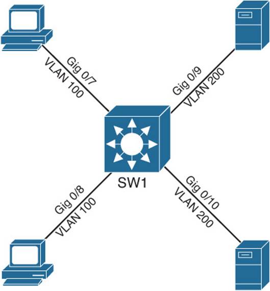
Figure 6-3 Layer 3 Switch Without IP addresses
Since Layer 2 switchports cannot be assigned an IP address; you need to create a logical Layer 3 interface known as a switched virtual interface (SVI). These SVIs can be assigned an IP address just like router interfaces. However, unlike router interfaces where an IP address is associated with one interface, the SVI represents all switchports that are part of the same VLAN the SVI is configured for. Therefore, any device connecting to the switch that is in VLAN 100 uses SVI 100, and any device in VLAN 200 uses SVI 200, and so on. This section explains how to configure SVIs on Layer 3 switches and the items that you should look out for when troubleshooting SVIs.
Reviewing SVIs
Figure 6-4 shows a topology using SVIs, and Example 6-17 shows the corresponding configuration. Notice that two SVIs are created: one for each VLAN. The SVI for VLAN 100 has the IP address 192.168.1.1/24, and the SVI for VLAN 200 has the IP address 192.168.2.1/24. Notice that these are two different subnets. As a result, devices that are members of VLAN 100 need to have an IP address in the 192.168.1.0/24 network and have their default gateway pointing to the VLAN 100 SVI IP address of 192.168.1.1. Devices that are members of VLAN 200 need to have an IP address in the 192.168.2.0/24 network and have their default gateway pointing to the VLAN 200 SVI IP address of 192.168.2.1. An IP address is assigned to an SVI by going into interface configuration mode for a VLAN. For example, the global configuration command interface vlan 10enters interface configuration mode for SVI 10 and, if not previously created, will create SVI 10. In this example, because both SVIs are local to the switch, the switch’s routing table knows how to forward traffic between members of the two VLANs. Also, IPv4 routing is not on by default on Layer 3 switches; therefore, you need to enable it with the ip routing global configuration command.
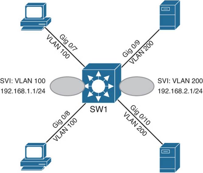
Figure 6-4 Layer 3 Switch with SVIs
Example 6-17 SW1 SVI Configuration
SW1#show run
...output omitted...
!
ip routing
!
...output omitted...
!
interface GigabitEthernet0/7
switchport access vlan 100
switchport mode access
!
interface GigabitEthernet0/8
switchport access vlan 100
switchport mode access
!
interface GigabitEthernet0/9
switchport access vlan 200
switchport mode access
!
interface GigabitEthernet0/10
switchport access vlan 200
switchport mode access
!
...output omitted...
!
interface Vlan100
ip address 192.168.1.1 255.255.255.0
!
interface Vlan200
ip address 192.168.2.1 255.255.255.0
Troubleshooting SVIs
For an SVI to function, the SVI status has to be up and the protocol has to be up. You can verify whether the SVI is up/up with a few different show commands, as shown in Example 6-18. In this case, the SVI for VLAN 100 is up/up, as shown in the output of show ip interface brief. The output of show interfaces vlan 100 also displays the SVI as being up/up, but it provides the MAC (bia) address that will be used when devices need to communicate directly with the SVI. For example, when hosts on VLAN 100 need to send a frame to the default gateway (remember the SVI will be the default gateway), they need a destination MAC address for the IP address associated for the SVI. It is this MAC that will be used in this case. The command also provides the IP address of the SVI. Lastly, the show ip interface vlan 100 command indicates that the SVI is up/up, in addition to providing us with the IP address.
Example 6-18 Verifying the Status of an SVI
SW1#show ip interface brief | include Vlan|Interface
Interface IP-Address OK? Method Status Protocol
Vlan1 unassigned YES NVRAM administratively down down
Vlan100 192.168.1.1 YES manual up up
Vlan200 192.168.2.1 YES manual up up
SW1#show interfaces vlan 100
Vlan100 is up, line protocol is up
Hardware is EtherSVI, address is 000d.2829.0200 (bia 000d.2829.0200)
Internet address is 192.168.1.1/24
MTU 1500 bytes, BW 1000000 Kbit, DLY 10 usec,
reliability 255/255, txload 1/255, rxload 1/255
...output omitted...
SW1#show ip interface vlan 100
Vlan100 is up, line protocol is up
Internet address is 192.168.1.1/24
Broadcast address is 255.255.255.255
Address determined by setup command
MTU is 1500 bytes
Helper address is not set
Directed broadcast forwarding is disabled
Outgoing access list is not set
Inbound access list is not set
...output omitted...
To successfully troubleshoot SVIs, you need to understand the circumstances that are necessary for an SVI to be up/up. The following list outlines what is needed for an SVI to be up/up:
![]() The VLAN the SVI is created for needs to exist locally on the switch.
The VLAN the SVI is created for needs to exist locally on the switch.
![]() The SVI has to be enabled and not administratively shut down.
The SVI has to be enabled and not administratively shut down.
![]() At a minimum, there must be one switchport (access or trunk) that is up/up and in the spanning-tree forwarding state for that specific VLAN.
At a minimum, there must be one switchport (access or trunk) that is up/up and in the spanning-tree forwarding state for that specific VLAN.
Note
To route from one SVI to another SVI, IP routing must be enabled on the Layer 3 switch with the ip routing command.
SVI Trouble Tickets
This section presents various trouble tickets relating to the topics discussed earlier in the chapter. The purpose of these trouble tickets is to give a process that you can follow when troubleshooting in the real world or in an exam environment. All trouble tickets in this section are based on the topology depicted in Figure 6-5.
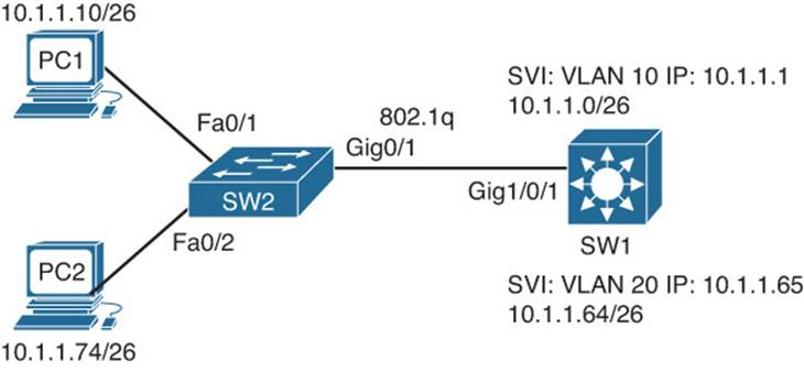
Figure 6-5 SVI Trouble Ticket Topology
Trouble Ticket 6-3
Problem: PC1 is not able to access resources on PC2.
Let’s start this trouble ticket by verifying the problem. Example 6-19 verifies that PC1 cannot access resources on PC2 because the ping has failed.
Example 6-19 Failed Ping from PC1 to PC2
C:\PC1>ping 10.1.1.74
Pinging 10.1.1.74 with 32 bytes of data:
Request timed out.
Request timed out.
Request timed out.
Request timed out.
Ping statistics for 10.1.1.74:
Packets: Sent = 4, Received = 0, Lost = 4 (100% loss),
Next, we ping the default gateway for PC1, and the result is not successful either, as shown in Example 6-20. This means that we have an issue from PC1 to the default gateway.
Example 6-20 Failed Ping from PC1 to Default Gateway
C:\PC1>ping 10.1.1.1
Pinging 10.1.1.1 with 32 bytes of data:
Request timed out.
Request timed out.
Request timed out.
Request timed out.
Ping statistics for 10.1.1.1:
Packets: Sent = 4, Received = 0, Lost = 4 (100% loss),
Following a structured troubleshooting approach, you would verify the IP configuration on PC1 as well as its MAC address using the ipconfig /all command. Example 6-21 indicates that the IP address, subnet mask, and default gateway are all correct based on Figure 6-5. It also indicates that the MAC address is 0800:275d:06d6.
Example 6-21 Verifying PC1s Configuration with ipconfig /all
C:\PC1>ipconfig /all
...output omitted...
Ethernet adapter Local Area Connection:
Connection-specific DNS Suffix . :
Description . . . . . . . . . . . : AMD PCNET Family PCI Ethernet Adapter
Physical Address. . . . . . . . . : 08-00-27-5D-06-D6
Dhcp Enabled. . . . . . . . . . . : No
IP Address. . . . . . . . . . . . : 10.1.1.10
Subnet Mask . . . . . . . . . . . : 255.255.255.192
Default Gateway . . . . . . . . . : 10.1.1.1
...output omitted...
Next we verify that SW2 is learning the MAC address of PC1 on the correct interface and that it is associated with the correct VLAN. Example 6-22 shows that the MAC address of PC1 (0800:275d:06d6) is associated with Fa0/1 and VLAN 10 with the command show mac address-table dynamic.
Example 6-22 Verifying SW2 Has Learned the MAC Address of PC1 on Fa0/1 and VLAN 10
SW2#show mac address-table dynamic
Mac Address Table
-------------------------------------------
Vlan Mac Address Type Ports
---- ----------- -------- -----
10 0800.275d.06d6 DYNAMIC Fa0/1
20 0800.27a2.ce47 DYNAMIC Fa0/2
20 2893.fe3a.e342 DYNAMIC Gi0/1
Total Mac Addresses for this criterion: 3
Next we issue the show mac address-table dynamic command on SW1, as shown in Example 6-23, to verify that the MAC address of PC1 is being learned on Gig1/0/1 and is associated with VLAN 10. In this case, it is not being learned at all. In addition, reviewing the output of Example 6-22 again concludes that there are no MAC addresses for VLAN 10 being learned on the Gig0/1 interface of SW2. We should see the MAC address of the default gateway for the 10.1.1.0/26 network associated with Gig0/1, but we don’t.
Example 6-23 Verifying SW1 Has Learned the MAC Address of PC1 on Gig1/0/1 and VLAN 10
SW1#show mac address-table dynamic
Mac Address Table
-------------------------------------------
Vlan Mac Address Type Ports
---- ----------- -------- -----
20 0800.27a2.ce47 DYNAMIC Gi1/0/1
Total Mac Addresses for this criterion: 1
Because SW1 is a Layer 3 switch, it should have an SVI for VLAN 10 with an IP address associated with it in the up/up state. Issuing the command show ip interface brief | include Vlan10, as shown in Example 6-24, indicates that the SVI exists on SW1, it has the IP address 10.1.1.1, and it is up/down. Therefore, the issue in this trouble ticket is causing MAC addresses not to be learned for VLAN 10 on SW1’s Gig1/0/1 and SW2’s Gig0/1 interfaces and is causing the SVI on SW1 to be up/down.
Example 6-24 Verifying SVI Exists on SW1 and Its Status
SW1#show ip interface brief | include VLAN10|Interface
Interface IP-Address OK? Method Status Protocol
Vlan10 10.1.1.1 YES NVRAM up down
What causes an SVIs protocol state to be down?
![]() The VLAN the SVI is created for does not exist locally on the switch.
The VLAN the SVI is created for does not exist locally on the switch.
![]() The SVI is administratively shut down.
The SVI is administratively shut down.
![]() There is no switchport (access or trunk) that is up/up and in the spanning-tree forwarding state for that specific VLAN.
There is no switchport (access or trunk) that is up/up and in the spanning-tree forwarding state for that specific VLAN.
What would cause MAC addresses not to be learned on trunk interfaces?
![]() The trunk has mismatched encapsulations, modes, native VLANs.
The trunk has mismatched encapsulations, modes, native VLANs.
![]() The trunk is manually or dynamically pruning traffic for the VLAN causing spanning tree to have no forwarding state for the VLAN.
The trunk is manually or dynamically pruning traffic for the VLAN causing spanning tree to have no forwarding state for the VLAN.
![]() The VLAN does not exist on the switch.
The VLAN does not exist on the switch.
Let’s compare these two lists. What do they have in common?
![]() The VLAN does not exist.
The VLAN does not exist.
![]() Spanning tree is not in the forwarding state for the VLAN on at least one interface.
Spanning tree is not in the forwarding state for the VLAN on at least one interface.
On SW1, the show interfaces trunk command enables you to see the spanning-tree forwarding state for each VLAN on Gig1/0/1. Example 6-25 shows the output of the command show interfaces trunk on SW1 and highlights the fact that SW1 interface Gig1/0/1 is not in the spanning-tree forwarding state for VLAN 10, only for VLAN 1 and 20. If you look further at the output, you see that VLAN 10 is not even listed in the list of VLANs that are active in the management domain. This is a good indication that VLAN 10 does not exist on SW1.
Example 6-25 Output of show interfaces trunk on SW1
SW1#show interfaces trunk
Port Mode Encapsulation Status Native vlan
Gi1/0/1 on 802.1q trunking 99
Port Vlans allowed on trunk
Gi1/0/1 1-4094
Port Vlans allowed and active in management domain
Gi1/0/1 1,20
Port Vlans in spanning tree forwarding state and not pruned
Gi1/0/1 1,20
Reviewing the output of show vlan brief on SW1 confirms that VLAN 10 does not exist, as shown in Example 6-26. Correcting this issue requires that you create the VLAN in global configuration mode using the vlan 10 command.
Example 6-26 Output of show vlan brief on SW1
SW1#show vlan brief
VLAN Name Status Ports
---- -------------------------------- --------- -------------------------------
1 default active Gi1/0/2, Gi1/0/3, Gi1/0/4
Gi1/0/5, Gi1/0/6, Gi1/0/7
Gi1/0/8, Gi1/0/9, Gi1/0/10
Gi1/0/11, Gi1/0/12, Gi1/0/13
Gi1/0/14, Gi1/0/15, Gi1/0/16
Gi1/0/17, Gi1/0/18, Gi1/0/19
Gi1/0/20, Gi1/0/21, Gi1/0/22
Gi1/0/23, Gi1/0/24, Te1/0/1,
Te1/0/2
20 10.1.1.64/26 active
1002 fddi-default act/unsup
1003 trcrf-default act/unsup
1004 fddinet-default act/unsup
1005 trbrf-default act/unsup
After you have corrected the issue, you want to confirm that the VLAN exists, as shown in the show vlan brief output of Example 6-27. You want to confirm that the output of show interfaces trunk lists VLAN 10 in the active VLANs in the management domain and that it is in the spanning-tree forwarding state and not pruned for interface Gig1/0/1, as shown in Example 6-28. In addition, you want to verify that the SVI for VLAN 10 is up/up by using the command show ip interface brief | include Vlan10, as shown in Example 6-29.
Example 6-27 Output of show vlan brief on SW1 After Changes
SW1#show vlan brief
VLAN Name Status Ports
---- -------------------------------- --------- -------------------------------
1 default active Gi1/0/2, Gi1/0/3, Gi1/0/4
Gi1/0/5, Gi1/0/6, Gi1/0/7
Gi1/0/8, Gi1/0/9, Gi1/0/10
Gi1/0/11, Gi1/0/12, Gi1/0/13
Gi1/0/14, Gi1/0/15, Gi1/0/16
Gi1/0/17, Gi1/0/18, Gi1/0/19
Gi1/0/20, Gi1/0/21, Gi1/0/22
Gi1/0/23, Gi1/0/24, Te1/0/1,
Te1/0/2
10 10.1.1.0/26 active
20 10.1.1.64/26 active
1002 fddi-default act/unsup
1003 trcrf-default act/unsup
1004 fddinet-default act/unsup
1005 trbrf-default act/unsup
Example 6-28 Output of show interfaces trunk on SW1 After Changes
SW1#show interfaces trunk
Port Mode Encapsulation Status Native vlan
Gi1/0/1 on 802.1q trunking 99
Port Vlans allowed on trunk
Gi1/0/1 1-4094
Port Vlans allowed and active in management domain
Gi1/0/1 1,10,20
Port Vlans in spanning tree forwarding state and not pruned
Gi1/0/1 1,10,20
Example 6-29 Output of show ip interface brief | include VLAN10 on SW1 After Changes
SW1#show ip interface brief | include VLAN10|Interface
Interface IP-Address OK? Method Status Protocol
Vlan10 10.1.1.1 YES NVRAM up up
Finally, you want to verify that the problem is solved by successfully pinging from PC1 to PC2. Example 6-30 shows that the problem is solved and that the ping is successful.
Example 6-30 Successful Ping from PC1 to PC2
C:\PC1>ping 10.1.1.74
Reply from 10.1.1.74: bytes=32 time 1ms TTL=128
Reply from 10.1.1.74: bytes=32 time 1ms TTL=128
Reply from 10.1.1.74: bytes=32 time 1ms TTL=128
Reply from 10.1.1.74: bytes=32 time 1ms TTL=128
Ping statistics for 10.1.1.74:
Packets: Sent = 4, Received = 4, Lost = 0 (0% loss),
Approximate round trip times in milli-seconds:
Minimum = 0ms, Maximum = 0ms, Average = 0ms
Trouble Ticket 6-4
Problem: PC1 is not able to access resources on PC2.
You start by verifying the problem, as shown in Example 6-31, which confirms (because the ping has failed) that PC1 is unable to access resources on PC2. Next you verify that PC1 can reach the default gateway, as shown in Example 6-32, which it can since the ping was successful. This confirms that no issue exists between PC1 and the default gateway. Next you verify that PC1 can reach the default gateway of VLAN 20, which is 10.1.1.65. Example 6-33 confirms that PC1 is able to reach the default gateway of VLAN 20 since the ping was successful as well.
Example 6-31 Failed Ping from PC1 to PC2
C:\PC1>ping 10.1.1.74
Pinging 10.1.1.74 with 32 bytes of data:
Request timed out.
Request timed out.
Request timed out.
Request timed out.
Ping statistics for 10.1.1.74:
Packets: Sent = 4, Received = 0, Lost = 4 (100% loss),
Example 6-32 Successful Ping from PC1 to VLAN 10 Default Gateway
C:\PC1>ping 10.1.1.1
Reply from 10.1.1.1: bytes=32 time 1ms TTL=128
Reply from 10.1.1.1: bytes=32 time 1ms TTL=128
Reply from 10.1.1.1: bytes=32 time 1ms TTL=128
Reply from 10.1.1.1: bytes=32 time 1ms TTL=128
Ping statistics for 10.1.1.1:
Packets: Sent = 4, Received = 4, Lost = 0 (0% loss),
Approximate round trip times in milli-seconds:
Minimum = 0ms, Maximum = 0ms, Average = 0ms
Example 6-33 Successful Ping from PC1 to VLAN 20 Default Gateway
PC1#ping 10.1.1.65
Reply from 10.1.1.65: bytes=32 time 1ms TTL=128
Reply from 10.1.1.65: bytes=32 time 1ms TTL=128
Reply from 10.1.1.65: bytes=32 time 1ms TTL=128
Reply from 10.1.1.65: bytes=32 time 1ms TTL=128
Ping statistics for 10.1.1.65:
Packets: Sent = 4, Received = 4, Lost = 0 (0% loss),
Approximate round trip times in milli-seconds:
Minimum = 0ms, Maximum = 0ms, Average = 0ms
Because all the pings were successful, this might mean that we have a problem between SW1 and PC2. Let’s ping from SW1 to PC2 to verify this. Example 6-34 provides the result of issuing the ping 10.1.1.74 command on SW1. Notice that the ping is successful, which negates our hypothesis that a problem might exist between SW1 and PC2.
Example 6-34 Successful Ping from SW1 to PC2
SW1#ping 10.1.1.74
Type escape sequence to abort.
Sending 5, 100-byte ICMP Echos to 10.1.1.74, timeout is 2 seconds:
!!!!!
Success rate is 100 percent (5/5), round-trip min/avg/max = 1/205/1015 ms
Let’s recap. PC1 can ping SVI 10, and PC2 can ping SVI 20. We also concluded that PC1 can ping SVI 20, which should mean that PC2 can ping SVI 10. Let’s double check by pinging from PC2 to the IP address 10.1.1.1. As shown in Example 6-35, it is successful as well.
Example 6-35 Successful Ping from PC2 to SVI 10
C:\PC2>ping 10.1.1.1
Reply from 10.1.1.1: bytes=32 time 1ms TTL=128
Reply from 10.1.1.1: bytes=32 time 1ms TTL=128
Reply from 10.1.1.1: bytes=32 time 1ms TTL=128
Reply from 10.1.1.1: bytes=32 time 1ms TTL=128
Ping statistics for 10.1.1.1:
Packets: Sent = 4, Received = 4, Lost = 0 (0% loss),
Approximate round trip times in milli-seconds:
Minimum = 0ms, Maximum = 0ms, Average = 0ms
So, the pings are getting a little more than halfway to their destination. What is required for the ping from PC1 to fully reach PC2? Routing.
Remember how the SVIs work. They are equivalent to router interfaces. Therefore, when you create an SVI, give it an IP address, and it is up/up, an entry for the network that the SVI belongs gets placed in the routing table. Issuing the command show ip interface brief on SW1, as shown inExample 6-36, confirms that the SVIs for VLAN 10 and VLAN 20 exist, they have the correct IP addresses assigned to them, and they are up/up.
Example 6-36 Output of show ip interface brief on SW1
SW1#show ip interface brief | include Vlan|Interface
Interface IP-Address OK? Method Status Protocol
Vlan1 unassigned YES NVRAM administratively down down
Vlan10 10.1.1.1 YES NVRAM up up
Vlan20 10.1.1.65 YES NVRAM up up
Let’s check the routing table on SW1 with the command show ip route. The output of show ip route, as shown in Example 6-37, does not even look like a routing table. Therefore, SW1 cannot route traffic. It can only respond to pings that are sent to its local interfaces. The output ofExample 6-37 should immediately lead you to the solution of this problem. The problem is that IP routing is not enabled on SW1. By default, on Layer 3 switches, IP routing is disabled. To enable it, you execute the ip routing command in global configuration mode.
Example 6-37 Output of show ip route on SW1
SW1#show ip route
Default gateway is not set
Host Gateway Last Use Total Uses Interface
ICMP redirect cache is empty
After you have enabled IP routing, you can issue the show ip route command again on SW1 to verify that directly connected entries have been added to the routing table for SVI VLAN 10 and SVI VLAN 20. Example 6-38 shows a routing table that we are familiar with and the directly connected entries for VLAN 10 and VLAN 20.
Example 6-38 Output of show ip route on SW1
SW1#show ip route
Codes: L - local, C - connected, S - static, R - RIP, M - mobile, B - BGP
D - EIGRP, EX - EIGRP external, O - OSPF, IA - OSPF inter area
N1 - OSPF NSSA external type 1, N2 - OSPF NSSA external type 2
E1 - OSPF external type 1, E2 - OSPF external type 2
i - IS-IS, su - IS-IS summary, L1 - IS-IS level-1, L2 - IS-IS level-2
ia - IS-IS inter area, * - candidate default, U - per-user static route
o - ODR, P - periodic downloaded static route, H - NHRP, l - LISP
+ - replicated route, % - next hop override
Gateway of last resort is not set
10.0.0.0/8 is variably subnetted, 6 subnets, 3 masks
C 10.1.1.0/26 is directly connected, Vlan10
L 10.1.1.1/32 is directly connected, Vlan10
C 10.1.1.64/26 is directly connected, Vlan20
L 10.1.1.65/32 is directly connected, Vlan20
Finally, we need to confirm that our solution solved the original issue, which was that PC1 could not access resources on PC2. Pinging from PC1 to PC2, as shown in Example 6-39, is successful, proving that we solved the issue.
Example 6-39 Successful Ping from PC1 to PC2
C:\PC1>ping 10.1.1.74
Reply from 10.1.1.74: bytes=32 time 1ms TTL=128
Reply from 10.1.1.74: bytes=32 time 1ms TTL=128
Reply from 10.1.1.74: bytes=32 time 1ms TTL=128
Reply from 10.1.1.74: bytes=32 time 1ms TTL=128
Ping statistics for 10.1.1.74:
Packets: Sent = 4, Received = 4, Lost = 0 (0% loss),
Approximate round trip times in milli-seconds:
Minimum = 0ms, Maximum = 0ms, Average = 0ms
Troubleshooting Routed Ports
Although SVIs can route between VLANs configured on a switch, a Layer 3 switch can be configured to act more as a router (for example, in an environment where you are replacing a router with a Layer 3 switch) by using routed ports on the switch. This section explains how to configure routed ports on Layer 3 switches so that you can identify potential problems during the troubleshooting process.
By default, the ports on many Layer 3 Cisco Catalyst switches operate as Layer 2 switchports. Therefore, you have to issue the no switchport command in interface configuration mode to convert a switchport to a routed port. Figure 6-6 and Example 6-40 illustrate a Layer 3 switch with its Gigabit Ethernet 0/9 and 0/10 ports configured as routed ports. You can verify whether a port is a routed port by using the show interfaces interface_type interface_number switchport command, as shown in Example 6-40 also. A routed port will state Switchport: Disabled.
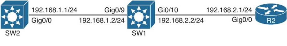
Figure 6-6 Routed Ports on a Layer 3 Switch
Example 6-40 Configuration for Routed Ports on a Layer 3 Switch
SW1#show run
...output omitted...
!
interface GigabitEthernet0/9
no switchport
ip address 192.168.1.2 255.255.255.0
!
interface GigabitEthernet0/10
no switchport
ip address 192.168.2.2 255.255.255.0
!
...output omitted...
SW1#show interfaces gigabitEthernet 0/10 switchport
Name: Gi0/10
Switchport: Disabled
The following list outlines the characteristics of routed ports:
![]() Has no association with any VLAN.
Has no association with any VLAN.
![]() Physical switchport that has Layer 3 (routing) capabilities.
Physical switchport that has Layer 3 (routing) capabilities.
![]() Does not run switchport protocols such as Spanning Tree Protocol (STP) or Dynamic Trunking Protocol (DTP).
Does not run switchport protocols such as Spanning Tree Protocol (STP) or Dynamic Trunking Protocol (DTP).
![]() Does not support subinterfaces like a router.
Does not support subinterfaces like a router.
![]() Useful for uplinks between Layer 3 switches or when connecting a Layer 3 switch to a router.
Useful for uplinks between Layer 3 switches or when connecting a Layer 3 switch to a router.
![]() To route from one routed port to another or a routed port to an SVI and vice versa, IP routing needs to be enabled.
To route from one routed port to another or a routed port to an SVI and vice versa, IP routing needs to be enabled.
Routed Ports Trouble Tickets
This section presents various trouble tickets relating to the topics discussed earlier in the chapter. The purpose of these trouble tickets is to give a process that you can follow when troubleshooting in the real world or in an exam environment. All trouble tickets in this section are based on the topology depicted in Figure 6-7.
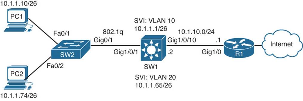
Figure 6-7 Routed Ports Trouble Tickets Topology
Trouble Ticket 6-5
Problem: PC1 and PC2 are not able to access resources outside their subnet.
You must always be sure that you fully understand the problem that is being submitted. Therefore, you always need to further define the problem to make sure that it is accurate. You ping from PC1 to the Internet, and it fails. You ping from PC2 to the Internet, and it fails. You ping from PC1 to its default gateway, and it is successful. You ping from PC2 to its default gateway, and it is successful. You ping from PC1 to PC2, and it is successful. Pinging from PC1 and PC2 to R1’s Gig1/0 interface fails. Therefore, the problem statement can be changed to read as follows:
Problem: PC1 and PC2 are not able to access resources beyond SW1. They are able to access each other.
This clarification allows us to focus our attention from SW1 onward, skipping all the Layer 2 troubleshooting between the PCs and SW1.
On SW1, you ping 10.1.10.1, as shown in Example 6-41, and it fails.
Example 6-41 Failed Ping from SW1 to R1
SW1#ping 10.1.10.1
Type escape sequence to abort.
Sending 5, 100-byte ICMP Echos to 10.1.10.1, timeout is 2 seconds:
.....
Success rate is 0 percent (0/5)
Next you issue the show ip interface brief command on SW1, as shown in Example 6-42, to verify that the correct IP address is configured on interface Gig1/0/10 and that it is up/up. The output shows that there is no IP address configured on Gig1/0/10 and that the interface is up/up.
Example 6-42 Output of show ip interface brief on SW1
SW1#show ip interface brief
Interface IP-Address OK? Method Status Protocol
...output omitted...
GigabitEthernet1/0/9 unassigned YES unset down down
GigabitEthernet1/0/10 unassigned YES unset up up
GigabitEthernet1/0/11 unassigned YES unset down down
...output omitted...
You enter interface configuration mode for Gig1/0/10 and issue the command ip address 10.1.10.2 255.255.255.0, as shown in Example 6-43. You receive the error message displayed in Example 6-43.
Example 6-43 Error message on SW1
SW1#config t
SW1(config)#interface gig 1/0/10
SW1(config-if)#ip address 10.1.10.2 255.255.255.0
^
% Invalid input detected at '^' marker.
As shown in Example 6-43, you are not able to configure an IP address on Gig1/0/10. This is a good indication that it is a Layer 2 switchport. You confirm this by issuing the show interface Gig1/0/10 switchport command. The output displayed in Example 6-44 indicates that it is indeed a Layer 2 switchport because the output states Switchport: Enabled. If it stated Switchport: Disabled, this would indicate that it is a routed port.
Example 6-44 Output of the show interfaces gig1/0/10 switchport Command on SW1
SW1#show interfaces gig1/0/10 switchport
Name: Gi1/0/10
Switchport: Enabled
Administrative Mode: dynamic auto
Operational Mode: static access
Administrative Trunking Encapsulation: negotiate
Operational Trunking Encapsulation: native
Negotiation of Trunking: On
Access Mode VLAN: 1 (default)
Trunking Native Mode VLAN: 1 (default)
...output omitted...
To assign an IP address to a switchport on a Layer 3 switch, you need to convert it to a routed port using the no switchport command in interface configuration mode, as shown in Example 6-45. Also in Example 6-45, you can see that the IP address command was successfully executed after the no switchport command was entered.
Example 6-45 Configuring a Routed Port on SW1
SW1#config t
SW1(config)#interface gig 1/0/10
SW1(config-if)#no switchport
SW1(config-if)#ip address 10.1.10.2 255.255.255.0
Now the ping from SW1 to R1 is successful, as displayed in Example 6-46. Also, the pings from PC1 and PC2 to the Internet are successful (not displayed).
Example 6-46 Successful Ping from SW1 to R1
SW1#ping 10.1.10.1
Type escape sequence to abort.
Sending 5, 100-byte ICMP Echos to 10.1.10.1, timeout is 2 seconds:
.!!!!
Success rate is 80 percent (4/5), round-trip min/avg/max = 9/14/17 ms
Troubleshooting Layer 3 EtherChannel
Chapter 5 discussed how to troubleshoot Layer 2 EtherChannels between Layer 2 switchports on Cisco Catalyst switches. When you have multiple routed ports on Layer 3 switches, you can bundle them together to create Layer 3 EtherChannels. This section focuses on the Layer 3 EtherChannel requirements and how you can successfully troubleshoot issues relating to it.
An EtherChannel logically combines the bandwidth of multiple physical interfaces into a logical connection between switches, as illustrated in Figure 6-8. Specifically, Figure 6-8 shows four Gigabit Ethernet routed ports logically bonded into a single EtherChannel link known as a port channel.
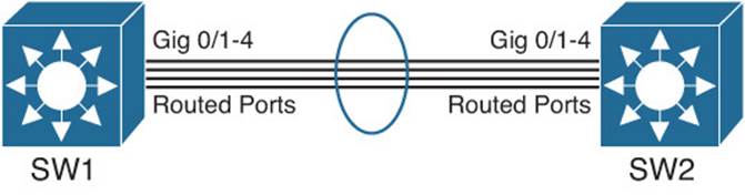
Figure 6-8 Layer 3 EtherChannel
Following are common troubleshooting targets to consider when troubleshooting a Layer 3 EtherChannel issue:
![]() Mismatched port configurations: The configurations of all ports making up an EtherChannel, on both switches, should be identical. For example, all ports should have the same speed and duplex and port type (Layer 2 or Layer 3). With Layer 3 EtherChannel, there is no need to worry about trunk mode, native VLAN configurations, and allowed VLAN configurations because we use routed ports, which are Layer 3 ports that do not care about those parameters.
Mismatched port configurations: The configurations of all ports making up an EtherChannel, on both switches, should be identical. For example, all ports should have the same speed and duplex and port type (Layer 2 or Layer 3). With Layer 3 EtherChannel, there is no need to worry about trunk mode, native VLAN configurations, and allowed VLAN configurations because we use routed ports, which are Layer 3 ports that do not care about those parameters.
![]() Port type during configuration: Creating an EtherChannel with the channel-group command before the port channel is created will automatically create the port channel with the same state as the physical ports bundled in the channel group. For example, if the physical interfaces are Layer 2 switchports, the port channel will be a Layer 2 port channel. If the physical interfaces are Layer 3 interfaces, the port channel will be a Layer 3 port channel. Therefore, it is imperative that you either make the physical interfaces routed ports with the no switchport command before creating the bundle or create the Layer 3 port channel with the interface port-channel interface_number command and issue the no switchport command in interface configuration mode before you configure the physical interfaces with the channel-group command. Order of operations is more important with Layer 3 EtherChannel than with Layer 2 EtherChannel.
Port type during configuration: Creating an EtherChannel with the channel-group command before the port channel is created will automatically create the port channel with the same state as the physical ports bundled in the channel group. For example, if the physical interfaces are Layer 2 switchports, the port channel will be a Layer 2 port channel. If the physical interfaces are Layer 3 interfaces, the port channel will be a Layer 3 port channel. Therefore, it is imperative that you either make the physical interfaces routed ports with the no switchport command before creating the bundle or create the Layer 3 port channel with the interface port-channel interface_number command and issue the no switchport command in interface configuration mode before you configure the physical interfaces with the channel-group command. Order of operations is more important with Layer 3 EtherChannel than with Layer 2 EtherChannel.
![]() Mismatched EtherChannel configuration: Both switches forming the EtherChannel should be configured for the same EtherChannel negotiation protocol. The options are Link Aggregation Control Protocol (LACP) and Port Aggregation Protocol (PAgP). If you prefer to statically configure EtherChannel, there is the on option as well. Table 6-2 identifies which options can be configured on each switch to successfully form an EtherChannel.
Mismatched EtherChannel configuration: Both switches forming the EtherChannel should be configured for the same EtherChannel negotiation protocol. The options are Link Aggregation Control Protocol (LACP) and Port Aggregation Protocol (PAgP). If you prefer to statically configure EtherChannel, there is the on option as well. Table 6-2 identifies which options can be configured on each switch to successfully form an EtherChannel.
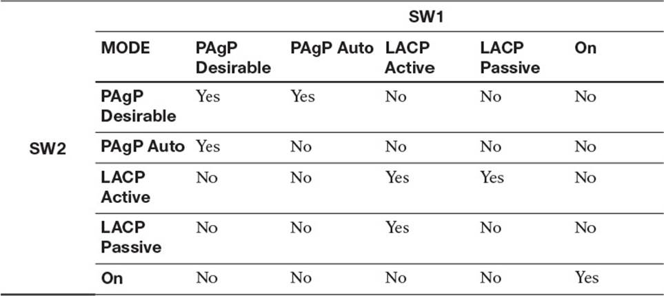
Table 6-2 Options for Successfully Forming an EtherChannel
![]() Inappropriate EtherChannel distribution algorithm: EtherChannel determines which physical link to use to transmit frames based on a hash calculation. The hashing approach selected should distribute the load fairly evenly across all physical links. For example, a hash calculation might be based only on the destination MAC address of a frame. If the frames are destined for only a few different MAC addresses, the load distribution could be uneven.
Inappropriate EtherChannel distribution algorithm: EtherChannel determines which physical link to use to transmit frames based on a hash calculation. The hashing approach selected should distribute the load fairly evenly across all physical links. For example, a hash calculation might be based only on the destination MAC address of a frame. If the frames are destined for only a few different MAC addresses, the load distribution could be uneven.
Verifying an EtherChannel bundle is done with the show etherchannel summary command, as shown in Example 6-47. With this output, you can verify the group number, the logical port channel number for the group, the status of the port channel, the protocol that was used, the ports in the bundle, and the status of the ports. In this example, the logical port channel is port channel 1, it is a Layer 3 port channel, and it is in use (as indicated by the RU). This is what you want to see; if you see any other combination, it means that you have a misconfiguration that is preventing the port channel from going up. Link Aggregation Control Protocol (LACP) was used as the protocol in this example, and Gig1/0/5 and 1/0/6 are bundled in the port channel, as indicated by the P. Again, you want to see P listed by the ports; if you see anything else, it means that you have a configuration issue that is preventing the port from being bundled. The only other option I would like to see beside the ports is H, which is used with LACP when you have more than eight ports in the bundle. When you have more than eight ports with LACP, the additional ports are placed in the standby state and used only if one of the main eight go down.
Example 6-47 Output of show etherchannel summary
SW1#show etherchannel summary
Flags: D - down P - bundled in port-channel
I - stand-alone s - suspended
H - Hot-standby (LACP only)
R - Layer3 S - Layer2
U - in use f - failed to allocate aggregator
M - not in use, minimum links not met
u - unsuitable for bundling
w - waiting to be aggregated
d - default port
Number of channel-groups in use: 1
Number of aggregators: 1
Group Port-channel Protocol Ports
------+-------------+-----------+--------------------------------------
1 Po1(RU) LACP Gi1/0/5(P) Gi1/0/6(P)
Layer 3 EtherChannel Trouble Tickets
This section presents various trouble tickets relating to the topics discussed earlier in the chapter. The purpose of these trouble tickets is to give a process that you can follow when troubleshooting in the real world or in an exam environment. All trouble tickets in this section are based on the topology depicted in Figure 6-9.
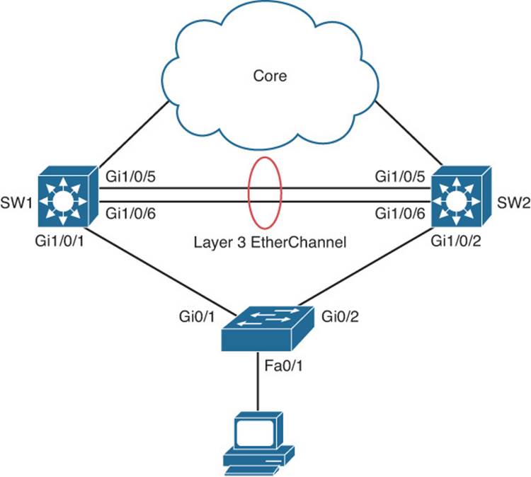
Figure 6-9 EtherChannel Trouble Tickets Topology
Trouble Ticket 6-6
Problem: A junior network administrator has approached you indicating that the Layer 3 EtherChannel they are trying to form between SW1 and SW2 is not forming. You need to solve this issue for them.
Your first step is to verify the EtherChannel configuration on SW1 and SW2 using the show etherchannel summary command, as shown in Example 6-48 and Example 6-49. Reviewing the flags on SW1 in Example 6-48 indicates that the ports are in standalone and that the port channel is Layer 2 down. Reviewing the flags on SW2 in Example 6-49 indicates that ports are suspended and that the port channel is Layer 3 down. Do you see the issue?
Example 6-48 SW1 show etherchannel summary Output
SW1#show etherchannel summary
Flags: D - down P - bundled in port-channel
I - stand-alone s - suspended
H - Hot-standby (LACP only)
R - Layer3 S - Layer2
U - in use f - failed to allocate aggregator
M - not in use, minimum links not met
u - unsuitable for bundling
w - waiting to be aggregated
d - default port
Number of channel-groups in use: 1
Number of aggregators: 1
Group Port-channel Protocol Ports
------+-------------+-----------+--------------------------------------
1 Po1(SD) LACP Gi1/0/5(I) Gi1/0/6(I)
Example 6-49 SW2 show etherchannel summary Output
SW2#show etherchannel summary
Flags: D - down P - bundled in port-channel
I - stand-alone s - suspended
H - Hot-standby (LACP only)
R - Layer3 S - Layer2
U - in use f - failed to allocate aggregator
M - not in use, minimum links not met
u - unsuitable for bundling
w - waiting to be aggregated
d - default port
Number of channel-groups in use: 1
Number of aggregators: 1
Group Port-channel Protocol Ports
------+-------------+-----------+--------------------------------------
1 Po1(RD) LACP Gi1/0/5(s) Gi1/0/6(s)
It appears that our junior network administrator failed to create a Layer 3 EtherChannel on SW1. If you recall, to create a Layer 3 EtherChannel, the physical ports and the port channel must be routed ports. Therefore, the junior network administrator forgot the no switchport command on SW1, as shown in Example 6-50.
Example 6-50 SW1 show run interface Output
SW1#show run int gig 1/0/5
!
interface GigabitEthernet1/0/5
switchport trunk encapsulation dot1q
switchport mode trunk
switchport nonegotiate
channel-group 1 mode active
end
SW1#show run int gig 1/0/6
!
interface GigabitEthernet1/0/6
switchport trunk encapsulation dot1q
switchport mode trunk
switchport nonegotiate
channel-group 1 mode active
end
SW1#show run int port-channel 1
!
interface Port-channel1
end
To solve this issue, you need to remove the port channel and channel group configuration from SW1, convert Gig1/0/5 and Gig1/0/6 to routed ports with the no switchport command, and then issue the channel-group mode command on Gig1/0/5 and Gig1/0/6, which will create the bundle and the Layer 3 port channel. Example 6-51 confirms that the Layer 3 EtherChannel bundle is now formed. Notice how the ports are bundled in the port channel and that the port channel is Layer 3 in use.
Example 6-51 SW1 and SW2 show etherchannel summary Output
SW1#show etherchannel summary
Flags: D - down P - bundled in port-channel
I - stand-alone s - suspended
H - Hot-standby (LACP only)
R - Layer3 S - Layer2
U - in use f - failed to allocate aggregator
M - not in use, minimum links not met
u - unsuitable for bundling
w - waiting to be aggregated
d - default port
Number of channel-groups in use: 1
Number of aggregators: 1
Group Port-channel Protocol Ports
------+-------------+-----------+--------------------------------------
1 Po1(RU) LACP Gi1/0/5(P) Gi1/0/6(P)
!
SW2#show etherchannel summary
Flags: D - down P - bundled in port-channel
I - stand-alone s - suspended
H - Hot-standby (LACP only)
R - Layer3 S - Layer2
U - in use f - failed to allocate aggregator
M - not in use, minimum links not met
u - unsuitable for bundling
w - waiting to be aggregated
d - default port
Number of channel-groups in use: 1
Number of aggregators: 1
Group Port-channel Protocol Ports
------+-------------+-----------+--------------------------------------
1 Po1(RU) LACP Gi1/0/5(P) Gi1/0/6(P)
Exam Preparation Tasks
As mentioned in the section “How to Use This Book” in the Introduction, you have a couple of choices for exam preparation: the exercises here; Chapter 22, “Final Preparation;” and the exam simulation questions on the CD-ROM.
Review All Key Topics
Review the most important topics in this chapter, noted with the Key Topic icon in the outer margin of the page. Table 6-3 lists a reference of these key topics and the page numbers on which each is found.
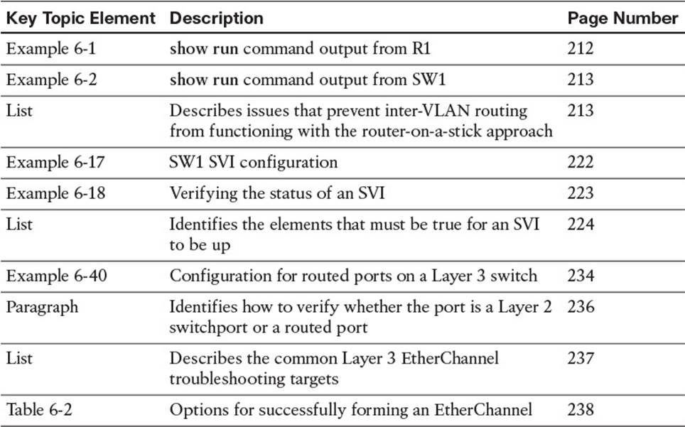
Table 6-3 Key Topics for Chapter 6
Define Key Terms
Define the following key terms from this chapter and check your answers in the glossary:
Layer 3 switch
router-on-a-trunk/router-on-a-stick
switched virtual interface (SVI)
routed port
Layer 3 EtherChannel
Complete Tables and Lists from Memory
Print a copy of Appendix C, “Memory Tables,” (found on the disc), or at least the section for this chapter, and complete the tables and lists from memory. Appendix D, “Memory Tables Answer Key,” also on the disc, includes completed tables and lists to check your work.
Show Command Reference to Check Your Memory
This section includes the show commands introduced in this chapter. It does not include the show commands that were used in this chapter but introduced in previous chapters. You will need to return to the previous chapters to review information relating to those show commands.
To test your memory of the commands, cover the right side of Table 6-4 with a piece of paper, read the description on the left side, and then see how much of the command you can remember.
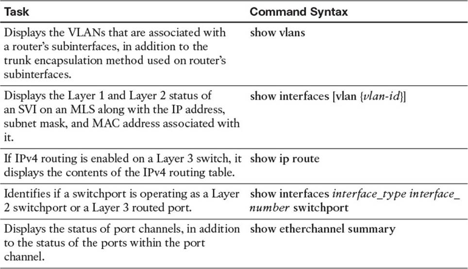
Table 6-4 show Commands Introduced in Chapter 6
The 300-135 TSHOOT exam focuses on practical, hands-on skills that are used by a networking professional. Therefore, you should be able to identify the show commands needed to successfully troubleshoot the topics presented in this chapter.
All materials on the site are licensed Creative Commons Attribution-Sharealike 3.0 Unported CC BY-SA 3.0 & GNU Free Documentation License (GFDL)
If you are the copyright holder of any material contained on our site and intend to remove it, please contact our site administrator for approval.
© 2016-2026 All site design rights belong to S.Y.A.