CCNP Routing and Switching TSHOOT 300-135 Official Cert Guide (2015)
Part II. Troubleshooting Cisco Catalyst Switch Features
Chapter 7. Troubleshooting Switch Security Features
This chapter covers the following topics:
![]() Troubleshooting Port Security: This section covers the various reasons why port security might not be performing as expected and how you can troubleshoot them.
Troubleshooting Port Security: This section covers the various reasons why port security might not be performing as expected and how you can troubleshoot them.
![]() Port Security Trouble Tickets: This section provides trouble tickets that demonstrate how you can use a structured troubleshooting process to solve a reported problem.
Port Security Trouble Tickets: This section provides trouble tickets that demonstrate how you can use a structured troubleshooting process to solve a reported problem.
![]() Troubleshooting Spoof-Prevention Features: This section explains the purpose of DHCP Snooping, Dynamic ARP Inspection, and IP Source Guard. In addition, you will learn what could cause these features not to perform as expected and how to troubleshoot them.
Troubleshooting Spoof-Prevention Features: This section explains the purpose of DHCP Snooping, Dynamic ARP Inspection, and IP Source Guard. In addition, you will learn what could cause these features not to perform as expected and how to troubleshoot them.
![]() Spoof-Prevention Features Trouble Tickets: This section provides trouble tickets that demonstrate how you can use a structured troubleshooting process to solve a reported problem.
Spoof-Prevention Features Trouble Tickets: This section provides trouble tickets that demonstrate how you can use a structured troubleshooting process to solve a reported problem.
![]() Troubleshooting Layer 2 Access Control: This section examines how to troubleshoot misconfigurations related to protected ports, private VLANs, and VLAN Access Control Lists.
Troubleshooting Layer 2 Access Control: This section examines how to troubleshoot misconfigurations related to protected ports, private VLANs, and VLAN Access Control Lists.
By default, switches are designed to provide connectivity. Therefore, out of the box, minimal security is applied. You can improve switch security by implementing features such as port security, DHCP snooping, dynamic Address Resolution Protocol (ARP) inspection, and IP Source Guard. In addition, by default, all traffic within a VLAN is free to flow between the switchports in the same VLAN. This might not be desired. Therefore, you can control the flow of traffic within the same VLAN with features such as protected ports, private VLANs, and VLAN access control lists (ACLs).
However, with these added features comes additional issues related to them that you will need to be able to troubleshoot. This chapter covers all these features and explores the various reasons why you may be experiencing issues and how you can troubleshoot them.
“Do I Know This Already?” Quiz
The “Do I Know This Already?” quiz allows you to assess whether you should read this entire chapter thoroughly or jump to the “Exam Preparation Tasks” section. If you are in doubt about your answers to these questions or your own assessment of your knowledge of the topics, read the entire chapter. Table 7-1 lists the major headings in this chapter and their corresponding “Do I Know This Already?” quiz questions. You can find the answers in Appendix A, “Answers to the ‘Do I Know This Already?’ Quizzes.”
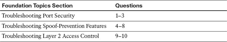
Table 7-1 “Do I Know This Already?” Section-to-Question Mapping
Caution
The goal of self-assessment is to gauge your mastery of the topics in this chapter. If you do not know the answer to a question or are only partially sure of the answer, you should mark that question as wrong for purposes of the self-assessment. Giving yourself credit for an answer that you correctly guess skews your self-assessment results and might provide you with a false sense of security.
1. Which command enables you to verify the port status of a port security-enabled port?
a. show port-security
b. show port-security interface interface_type interface_number
c. show port-security address
d. show running-configuration
2. Which two of the following port security violation modes will generate a log message when a violation occurs?
a. Protect
b. Restrict
c. Shutdown
d. Disabled
3. Which two commands identify the ports that are in the err-disabled state if the err-disable recovery feature has not been enabled for port security?
a. show running-configuration
b. show interfaces
c. show interfaces status
d. show port-security address
4. What must be true for DHCP snooping to operate successfully? (Choose two.)
a. It must be enabled globally.
b. It must be enabled for specific VLANs.
c. The ports going to end stations must be configured as trusted.
d. The ports going to the DHCP servers need to be configured as untrusted.
5. Which command enables you to verify the IP address that has been given to each client from the DHCP server along with the interface they are connected to and the VLAN the interface is a member of?
a. show ip dhcp snooping
b. show ip dhcp snooping binding
c. show ip dhcp snooping database
d. show ip dhcp snooping statistics
6. What must be true for dynamic ARP inspection to operate successfully? (Choose two answers.)
a. DHCP snooping must be enabled globally.
b. DHCP snooping must be enabled for specific VLANs.
c. IP ARP inspection must be enabled for specific VLANs.
d. All interfaces, except for upstream interfaces, need to be configured as trusted interfaces.
7. How does IP Source Guard learn where valid source IPs are in the network?
a. ARP cache
b. MAC address table
c. DHCP snooping database
d. Routing table
8. Which command enables you to verify which interfaces have been configured with IP Source Guard?
a. show ip arp
b. show ip verify source
c. show interfaces status
d. show ip dhcp snooping binding
9. Which two of the following statements are true about PVLANs?
a. Community ports cannot communicate with other community ports in the same community.
b. Community ports can communicate with other community ports in a different community.
c. Community ports cannot communicate with isolated ports and vice versa.
d. Isolated ports cannot communicate with other isolated ports.
10. Which of the following has the ability to deny only FTP traffic between two devices in the same VLAN?
a. IP Source Guard
b. Protected ports
c. Private VLANs
d. VLAN ACL
Foundation Topics
Troubleshooting Port Security
The port security feature is designed to control a specific set/number of MAC addresses that will be learned on an interface. This helps to eliminate CAM table flooding attacks, where a malicious user attempts to overflow the CAM table by populating it with a large number of bogus MAC addresses. In addition, it ensures that only specific devices (based on MAC address) can connect to certain switchports. Therefore, port security is a must for all organizations to implement. However, as with all services and features, if something goes wrong, you will be troubleshooting. This section shows you how to identify and troubleshoot port security issues.
Common Port Security Issues
Usually, port security will perform as expected with minimal issues. If an attack occurs, port security kicks in; if not, port security keeps waiting. Most issues arise from misconfigurations. The following is a listing of issues that may occur when working with port security:

![]() Port security is configured but not enabled.
Port security is configured but not enabled.
![]() A static MAC address was not configured correctly.
A static MAC address was not configured correctly.
![]() The maximum number of MAC addresses has been reached, preventing access.
The maximum number of MAC addresses has been reached, preventing access.
![]() Legitimate users are being blocked because of a violation.
Legitimate users are being blocked because of a violation.
![]() Running configuration not saved to startup configuration.
Running configuration not saved to startup configuration.
Port Security Configured but Not Enabled
Example 7-1 provides a port security configuration on interface Fast Ethernet 0/1 of an access layer switch. Notice that all commands start with switchport port-security. However, if you fail to include the command switchport port-security (which is highlighted), port security is not enabled on the interface regardless of the rest of the configuration specified.
Example 7-1 Sample Port Security Configuration
SW1#show running-config interface fastEthernet 0/1
Building configuration...
Current configuration : 456 bytes
!
interface FastEthernet0/1
switchport access vlan 10
switchport mode access
switchport port-security maximum 2
switchport port-security
switchport port-security violation restrict
switchport port-security mac-address sticky
switchport port-security mac-address sticky 0050.b607.657a
switchport port-security mac-address 0800.275d.06d6
Use the commands show port-security and show port-security interface interface_type interface_number to verify whether port security is enabled on an interface, as shown in Example 7-2. In this case, Fast Ethernet 0/1 is enabled for port security.
Example 7-2 Verifying Port Security Is Enabled on an Interface
SW1#show port-security
Secure Port MaxSecureAddr CurrentAddr SecurityViolation Security Action
(Count) (Count) (Count)
---------------------------------------------------------------------------
Fa0/1 2 2 0 Restrict
---------------------------------------------------------------------------
Total Addresses in System (excluding one mac per port) : 1
Max Addresses limit in System (excluding one mac per port) : 8192
ASW1#show port-security interface fastEthernet 0/1
Port Security : Enabled
Port Status : Secure-up
Violation Mode : Restrict
Aging Time : 0 mins
Aging Type : Absolute
SecureStatic Address Aging : Disabled
Maximum MAC Addresses : 2
Total MAC Addresses : 2
Configured MAC Addresses : 0
Sticky MAC Addresses : 2
Last Source Address:Vlan : 0800.275d.06d6:10
Security Violation Count : 0
Static MAC Address Not Configured Correctly
If you have implemented port security by defining MAC addresses statically, it is imperative that they are accurate. If a user complains that he cannot access the network after receiving a new computer and your network relies on static port security addresses, you more than likely forgot to change the port security static MAC address. Example 7-3 identifies the static MAC address configuration for 0800.275d.06d6.
Example 7-3 Sample Static MAC Address Port Security Configuration
SW1#show running-config interface fastEthernet 0/1
Building configuration...
Current configuration : 456 bytes
!
interface FastEthernet0/1
switchport access vlan 10
switchport mode access
switchport port-security maximum 2
switchport port-security
switchport port-security violation restrict
switchport port-security mac-address sticky
switchport port-security mac-address sticky 0050.b607.657a
switchport port-security mac-address 0800.275d.06d6
Using the show port-security address command reveals the static MAC address configured for the interfaces, as shown in Example 7-4. In this example, the MAC address 0800.275d.06d6 is a statically configured (SecureConfigured) port security MAC address for Fa0/1 and VLAN 10. You need to compare this to the MAC address of the PC connected to the port with the ipconfig /all command, as shown in Example 7-5. (This is where accurate documentation is helpful.) The show port-security address command will also identify the dynamically learned port security MAC addresses and the sticky secure MAC addresses.
Example 7-4 Verifying Static Addresses Associated with Interfaces
SW1#show port-security address
Secure Mac Address Table
-----------------------------------------------------------------------------
Vlan Mac Address Type Ports Remaining Age
(mins)
---- ----------- ---- ----- -------------
10 0050.b607.657a SecureSticky Fa0/1 -
10 0800.275d.06d6 SecureConfigured Fa0/1 -
-----------------------------------------------------------------------------
Total Addresses in System (excluding one mac per port) : 1
Max Addresses limit in System (excluding one mac per port) : 8192
Example 7-5 Verifying MAC Address of PC.
PC1#ipconfig /all
Windows IP Configuration
Host Name . . . . . . . . . . . . : pc1
Primary Dns Suffix . . . . . . . :
Node Type . . . . . . . . . . . . : Broadcast
IP Routing Enabled. . . . . . . . : No
WINS Proxy Enabled. . . . . . . . : No
Ethernet adapter PC1 Lab:
Connection-specific DNS Suffix . :
Description . . . . . . . . . . . : AMD PCNET Family PCI Ethernet Adapter
Physical Address. . . . . . . . . : 08-00-27-5D-06-D6
Dhcp Enabled. . . . . . . . . . . : No
...output omitted...
Maximum Number of MAC Addresses Reached
By default, when port security is enabled, only one MAC address will be allowed. Therefore, if you need more than one MAC address, you have to specify the number with the switchport port-security maximum number command, as shown in Example 7-6. In this case, the maximum number was set to 2 so that two devices could communicate through the interface.
Example 7-6 Identifying the Maximum Number of MAC Addresses Allowed
SW1#show running-config interface fastEthernet 0/1
Building configuration...
Current configuration : 456 bytes
!
interface FastEthernet0/1
switchport access vlan 10
switchport mode access
switchport port-security maximum 2
switchport port-security
switchport port-security violation restrict
switchport port-security mac-address sticky
switchport port-security mac-address sticky 0050.b607.657a
switchport port-security mac-address 0800.275d.06d6
You can verify the maximum number of MAC addresses allowed on an interface with the show port-security and show port-security interface interface_type interface_number commands. As shown in Example 7-7, two MACs are allowed, and two have been learned.
Example 7-7 Identifying the Maximum Number of MAC Addresses Allowed
SW1#show port-security
Secure Port MaxSecureAddr CurrentAddr SecurityViolation Security Action
(Count) (Count) (Count)
---------------------------------------------------------------------------
Fa0/1 2 2 0 Restrict
---------------------------------------------------------------------------
Total Addresses in System (excluding one mac per port) : 1
Max Addresses limit in System (excluding one mac per port) : 8192
SW1#show port-security interface fastEthernet 0/1
Port Security : Enabled
Port Status : Secure-up
Violation Mode : Restrict
Aging Time : 0 mins
Aging Type : Absolute
SecureStatic Address Aging : Disabled
Maximum MAC Addresses : 2
Total MAC Addresses : 2
Configured MAC Addresses : 1
Sticky MAC Addresses : 1
Last Source Address:Vlan : 0800.275d.06d6:10
Security Violation Count : 0
Legitimate Users Being Blocked Because of Violation
You need to make sure that you have the correct number of MAC addresses specified. If the number is not correct, a violation will occur if more than the specified number of MAC addresses are seen on the port. The violation will occur regardless of the additional MAC addresses being accidental or malicious. Three different violations exist:
![]() Protect: Any frame from the MAC addresses in violation is dropped without a notification, and the violation count is not incremented.
Protect: Any frame from the MAC addresses in violation is dropped without a notification, and the violation count is not incremented.
![]() Restrict: Any frame from the MAC addresses in violation is dropped, and log messages are generated.
Restrict: Any frame from the MAC addresses in violation is dropped, and log messages are generated.
![]() Shutdown: When a violation occurs, the port is placed in the err-disabled state, and any frame from any MAC address will be dropped. In addition, log messages will be generated.
Shutdown: When a violation occurs, the port is placed in the err-disabled state, and any frame from any MAC address will be dropped. In addition, log messages will be generated.
Tip
You can remember that these get more severe in alphabetic order (P/R/S) (drop/drop&alert/shutdown&alert).
You can verify whether there is a violation by using the show port-security and show port-security interface interface_type interface_number commands, as shown in Example 7-8. In this case, there is currently no violation. However, if there were, the security violation count would increment, and because the violation mode is Restrict, any frame from the MAC addresses in violation is dropped, and log messages are generated.
Example 7-8 Identifying Security Violations
SW1#show port-security
Secure Port MaxSecureAddr CurrentAddr SecurityViolation Security Action
(Count) (Count) (Count)
---------------------------------------------------------------------------
Fa0/1 2 2 0 Restrict
---------------------------------------------------------------------------
Total Addresses in System (excluding one mac per port) : 1
Max Addresses limit in System (excluding one mac per port) : 8192
SW1#show port-security interface fastEthernet 0/1
Port Security : Enabled
Port Status : Secure-up
Violation Mode : Restrict
Aging Time : 0 mins
Aging Type : Absolute
SecureStatic Address Aging : Disabled
Maximum MAC Addresses : 2
Total MAC Addresses : 2
Configured MAC Addresses : 1
Sticky MAC Addresses : 1
Last Source Address:Vlan : 0800.275d.06d6:10
Security Violation Count : 0
If the violation mode is set to shutdown, as shown in Example 7-9, and a violation occurs, the port status is Secure-shutdown and placed in the err-disable state, as displayed in the following syslog messages:
%PM-4-ERR_DISABLE: psecure-violation error detected on Fa0/1, putting Fa0/1 in
err-disable state
%PORT_SECURITY-2-PSECURE_VIOLATION: Security violation occurred, caused by MAC
address 0800.27a2.ce47 on port FastEthernet0/1.
%LINEPROTO-5-UPDOWN: Line protocol on Interface FastEthernet0/1, changed state to
down
%LINK-3-UPDOWN: Interface FastEthernet0/1, changed state to down
Example 7-9 Example Port That Has Been Shut Down and Placed in the Err-Disable State
SW1#show port-security interface fastEthernet 0/1
Port Security : Enabled
Port Status : Secure-shutdown
Violation Mode : Shutdown
Aging Time : 0 mins
Aging Type : Absolute
SecureStatic Address Aging : Disabled
Maximum MAC Addresses : 2
Total MAC Addresses : 2
Configured MAC Addresses : 1
Sticky MAC Addresses : 1
Last Source Address:Vlan : 0800.27a2.ce47:10
Security Violation Count : 1
To verify ports that are in the err-disabled state, use the command show interfaces status, as shown in Example 7-10. You can also use the show interface interface_type interface_number command. As you can see, Fa0/1 is in the err-disabled state. However, it does not tell you what caused the err-disabled state. Example 7-11 displays all the different services that can cause a port to go into the err-disabled state. Notice that they are all enabled by default and that port security is one of them (psecure-violation).
Example 7-10 Identifying Ports in the Err-Disabled State
SW1#show interfaces status
Port Name Status Vlan Duplex Speed Type
Fa0/1 err-disabled 10 auto auto 10/100BaseTX
Fa0/2 connected 10 a-full a-100 10/100BaseTX
Fa0/3 notconnect 1 auto auto 10/100BaseTX
Fa0/4 notconnect 1 auto auto 10/100BaseTX
Fa0/5 notconnect 1 auto auto 10/100BaseTX
Fa0/6 notconnect 1 auto auto 10/100BaseTX
...output omitted...
SW1#show interfaces fastEthernet 0/1
FastEthernet0/1 is down, line protocol is down (err-disabled)
Hardware is Fast Ethernet, address is 081f.f34e.b801 (bia 081f.f34e.b801)
Example 7-11 Identifying Which Services Are Enabled for Err-Disable
SW1#show errdisable detect
ErrDisable Reason Detection Mode
----------------- --------- ----
arp-inspection Enabled port
bpduguard Enabled port
channel-misconfig (STP) Enabled port
community-limit Enabled port
dhcp-rate-limit Enabled port
dtp-flap Enabled port
gbic-invalid Enabled port
iif-reg-failure Enabled port
inline-power Enabled port
invalid-policy Enabled port
link-flap Enabled port
loopback Enabled port
lsgroup Enabled port
mac-limit Enabled port
pagp-flap Enabled port
port-mode-failure Enabled port
pppoe-ia-rate-limit Enabled port
psecure-violation Enabled port/vlan
security-violation Enabled port
sfp-config-mismatch Enabled port
sgacl_limitation Enabled port
small-frame Enabled port
storm-control Enabled port
udld Enabled port
vmps Enabled port
psp Enabled port
The best way to determine why a port is in the err-disabled state is to review syslog messages. They are listed as severity level 4, and the mnemonic is ERR-DISABLE. In this case, the message text clearly states it was caused by a port security violation.
%PM-4-ERR_DISABLE: psecure-violation error detected on Fa0/1, putting Fa0/1 in
err-disable state
Tip
If for some reason you do not have access to the syslog messages, bounce (shut/noshut) the interface that is err-disabled. By doing so, after the interface is enabled, the error will be detected again, which will generate a syslog message. Make sure that logging to the console or terminal lines is enabled, and do not forget about the terminal monitor command if you are using Telnet or Secure Shell (SSH). This process is shown in Example 7-12, and you can see that the port was err-disabled due to a port security violation.
Example 7-12 Bouncing the Interface to Determine Why It Is Err-Disabled
SW1#config t
Enter configuration commands, one per line. End with CNTL/Z.
SW1(config)#interface fastEthernet 0/1
SW1(config-if)#shut
%LINK-5-CHANGED: Interface FastEthernet0/1, changed state to administratively down
SW1(config-if)#no shut
%LINK-3-UPDOWN: Interface FastEthernet0/1, changed state to up
%PM-4-ERR_DISABLE: psecure-violation error detected on Fa0/1, putting Fa0/1 in err-
disable state
SW1(config-if)#
%PORT_SECURITY-2-PSECURE_VIOLATION: Security violation occurred, caused by MAC
address 0800.27a2.ce47 on port FastEthernet0/1.
SW1(config-if)#
%LINK-3-UPDOWN: Interface FastEthernet0/1, changed state to down
If you are relying on the err-disable recovery feature to enable interfaces once the violation is no longer detected, you can verify the status of the feature with the show errdisable recovery command, as shown in Example 7-13. Notice that the err-disable recovery feature is disabled by default for all the different services and features. Therefore, if you need to use it, it has to be manually enabled by you.
Example 7-13 Verifying the Err-Disable Recovery Feature
SW1#show errdisable recovery
ErrDisable Reason Timer Status
----------------- --------------
arp-inspection Disabled
bpduguard Disabled
channel-misconfig (STP) Disabled
dhcp-rate-limit Disabled
dtp-flap Disabled
gbic-invalid Disabled
inline-power Disabled
link-flap Disabled
mac-limit Disabled
loopback Disabled
pagp-flap Disabled
port-mode-failure Disabled
pppoe-ia-rate-limit Disabled
psecure-violation Disabled
security-violation Disabled
sfp-config-mismatch Disabled
small-frame Disabled
storm-control Disabled
udld Disabled
vmps Disabled
psp Disabled
Timer interval: 300 seconds
Interfaces that will be enabled at the next timeout:
To enable err-disable recovery for a specific feature or service, issue the errdisable recovery cause service/feature global configuration command, as shown in Example 7-14. This example displays all the different options available on a Catalyst 2960 switch.
Example 7-14 Enabling the Err-Disable Recovery Feature
SW1(config)#errdisable recovery cause ?
all Enable timer to recover from all error causes
arp-inspection Enable timer to recover from arp inspection error
disable state
bpduguard Enable timer to recover from BPDU Guard error
channel-misconfig (STP) Enable timer to recover from channel misconfig error
dhcp-rate-limit Enable timer to recover from dhcp-rate-limit error
dtp-flap Enable timer to recover from dtp-flap error
gbic-invalid Enable timer to recover from invalid GBIC error
inline-power Enable timer to recover from inline-power error
link-flap Enable timer to recover from link-flap error
loopback Enable timer to recover from loopback error
mac-limit Enable timer to recover from mac limit disable state
pagp-flap Enable timer to recover from pagp-flap error
port-mode-failure Enable timer to recover from port mode change
failure
pppoe-ia-rate-limit Enable timer to recover from PPPoE IA rate-limit
error
psecure-violation Enable timer to recover from psecure violation error
psp Enable timer to recover from psp
security-violation Enable timer to recover from 802.1x violation error
sfp-config-mismatch Enable timer to recover from SFP config mismatch
error
small-frame Enable timer to recover from small frame error
storm-control Enable timer to recover from storm-control error
udld Enable timer to recover from udld error
vmps Enable timer to recover from vmps shutdown error
When using the err-disable recovery feature, you have an extra piece of information you can use. Suppose, for instance, that you enable it for port security. At the bottom of the show errdisable recovery output, information identifies what interface is err-disabled and why, as shown inExample 7-15. This makes it easier for you to troubleshoot what caused the port to be err-disabled. It also indicates how much time is left until the port is automatically enabled. If the violation still exists at that point, it will be err-disabled again.
Example 7-15 Verifying the Err-Disable Reason
SW1#show errdisable recovery
ErrDisable Reason Timer Status
----------------- --------------
arp-inspection Disabled
bpduguard Disabled
channel-misconfig (STP) Disabled
dhcp-rate-limit Disabled
dtp-flap Disabled
gbic-invalid Disabled
inline-power Disabled
link-flap Disabled
mac-limit Disabled
loopback Disabled
pagp-flap Disabled
port-mode-failure Disabled
pppoe-ia-rate-limit Disabled
psecure-violation Enabled
security-violation Disabled
sfp-config-mismatch Disabled
small-frame Disabled
storm-control Disabled
udld Disabled
vmps Disabled
psp Disabled
Timer interval: 300 seconds
Interfaces that will be enabled at the next timeout:
Interface Errdisable reason Time left(sec)
--------- ----------------- --------------
Fa0/1 psecure-violation 85
Running Configuration Not Saved to Startup Configuration
This is pretty obvious: If you fail to save the running configuration to the NVRAM, the port security configuration will no longer be available when the switch reboots. However, many administrators who use the port security sticky feature forget about saving the configuration when a new PC is added. The sticky feature allows the switch to dynamically learn MAC addresses and then place the MAC address in the configuration just like they had been statically configured. Example 7-16 displays the port security sticky configuration on a switch. Notice how the sticky feature was enabled with the switchport port-security mac-address sticky command. Once the MAC address 0050.b607.657a was learned by the switch on interface Fast Ethernet 0/1, the switch placed it in the configuration with the switchport port-security mac-address sticky 0050.b607.657acommand. You now need to save the configuration; otherwise, the sticky-learned MAC address will not be in the configuration if the switch reboots.
Example 7-16 Port Security Sticky Configuration
SW1#show running-config interface fastEthernet 0/1
Building configuration...
Current configuration : 456 bytes
!
interface FastEthernet0/1
switchport access vlan 10
switchport mode access
switchport port-security maximum 2
switchport port-security
switchport port-security violation restrict
switchport port-security mac-address sticky
switchport port-security mac-address sticky 0050.b607.657a
switchport port-security mac-address 0800.275d.06d6
Port Security Trouble Tickets
This section presents various trouble tickets relating to the topics discussed earlier in the chapter. The purpose of these trouble tickets is to give a process that you can follow when troubleshooting in the real world or in an exam environment. All trouble tickets in this section are based on the topology depicted in Figure 7-1.
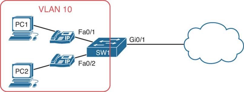
Figure 7-1 Port Security Trouble Ticket Topology
Trouble Ticket 7-1
Problem: It is Monday morning, and the user on PC1 has called you indicating that she is not able to access any network resources.
You ask her when the last time it was that she was able to access resources. She indicates that it was 2 weeks ago, before she went on vacation. This leads you to examine the change control documentation to determine whether any configuration changes were done in the past 2 weeks. You notice that port security was added to all access ports on SW1. Therefore, you decide to start your troubleshooting process by examining the port security configuration on SW1.
According to documentation, PC1 is connected to Fa0/1. You issue the command show port-security, as shown in Example 7-17, and notice that Fa0/1 is enabled for port security and that there is a security violation count of 1.
Example 7-17 Verifying Port Security on Fa0/1
SW1#show port-security
Secure Port MaxSecureAddr CurrentAddr SecurityViolation Security Action
(Count) (Count) (Count)
---------------------------------------------------------------------------
Fa0/1 2 2 1 Shutdown
Fa0/2 2 2 0 Shutdown
Fa0/3 2 0 0 Shutdown
Fa0/4 2 0 0 Shutdown
Fa0/5 2 0 0 Shutdown
Fa0/6 2 0 0 Shutdown
Fa0/7 2 0 0 Shutdown
Fa0/8 2 0 0 Shutdown
Fa0/9 2 0 0 Shutdown
Fa0/10 2 0 0 Shutdown
Fa0/11 2 0 0 Shutdown
Fa0/12 2 0 0 Shutdown
Fa0/13 2 0 0 Shutdown
Fa0/14 2 0 0 Shutdown
Fa0/15 2 0 0 Shutdown
Fa0/16 2 0 0 Shutdown
Fa0/17 2 0 0 Shutdown
Fa0/18 2 0 0 Shutdown
Fa0/19 2 0 0 Shutdown
Fa0/20 2 0 0 Shutdown
Fa0/21 2 0 0 Shutdown
Fa0/22 2 0 0 Shutdown
Fa0/23 2 0 0 Shutdown
Fa0/24 2 0 0 Shutdown
---------------------------------------------------------------------------
Total Addresses in System (excluding one mac per port) : 2
Max Addresses limit in System (excluding one mac per port) : 8192
To verify the status of port security for Fa0/1 you issue the command show port-security interface fastEthernet 0/1, as shown in Example 7-18. Port security is enabled but it is in the Secure-shutdown state. The last MAC address that was received on the interface was 0800.275d.06d6 for VLAN 10.
Example 7-18 Verifying Port Security Status on Fa0/1
SW1#show port-security interface fastEthernet 0/1
Port Security : Enabled
Port Status : Secure-shutdown
Violation Mode : Shutdown
Aging Time : 0 mins
Aging Type : Absolute
SecureStatic Address Aging : Disabled
Maximum MAC Addresses : 2
Total MAC Addresses : 2
Configured MAC Addresses : 2
Sticky MAC Addresses : 0
Last Source Address:Vlan : 0800.275d.06d6:10
Security Violation Count : 1
Next you issue the show run interface fa0/1 command to verify the port security configuration on Fa0/1. As shown in Example 7-19, it has been enabled, the maximum MAC addresses is set to 2, and there are 2 MAC addresses configured (one for the phone and one for PC1).
Example 7-19 Verifying Port Security Configuration on Fa0/1
SW1#show run interface fa0/1
Building configuration...
Current configuration : 352 bytes
!
interface FastEthernet0/1
switchport access vlan 10
switchport mode access
switchport port-security maximum 2
switchport port-security
switchport port-security mac-address 0050.b607.657a
switchport port-security mac-address 0800.275d.06d7
no lldp transmit
spanning-tree portfast
spanning-tree bpduguard enable
spanning-tree guard root
end
You decide to confirm the MAC addresses of the IP Phone and PC1. Starting with the PC, you issue the ipconfig /all command, as shown in Example 7-20. The MAC address of PC1 is 08-00-27-5D-06-D6, which happens to be the same MAC address that caused the violation shown inExample 7-18. Comparing the MAC address of PC1 to the addresses statically configured on Fa0/1, as shown in Example 7-19, confirms that PC1s MAC address is not one of the addresses configured.
Example 7-20 Reviewing the MAC Address on PC1
C:\>ipconfig /all
Windows IP Configuration
Host Name . . . . . . . . . . . . : pc1
Primary Dns Suffix . . . . . . . :
Node Type . . . . . . . . . . . . : Broadcast
IP Routing Enabled. . . . . . . . : No
WINS Proxy Enabled. . . . . . . . : No
Ethernet adapter PC1 Lab:
Connection-specific DNS Suffix . :
Description . . . . . . . . . . . : AMD PCNET Family PCI Ethernet Adapter
Physical Address. . . . . . . . . : 08-00-27-5D-06-D6
Dhcp Enabled. . . . . . . . . . . : Yes
Autoconfiguration Enabled . . . . : Yes
Autoconfiguration IP Address. . . : 169.254.180.166
Subnet Mask . . . . . . . . . . . : 255.255.0.0
...output omitted...
After confirming that the IP Phone’s MAC address is 0050.b607.657a, you conclude that the command switchport port-security mac-address 0050.b607.657a is correct but that the command switchport port-security mac-address 0800.275d.06d7 is not correct. It appears that the static MAC address was misconfigured with a 7 at the end rather than a 6.
You proceed to remove the incorrect static MAC address with the no switchport port-security mac-address 0800.275d.06d7 command and replace it with the MAC address of PC1. Example 7-21 provides the configuration that is needed to solve the issue.
Example 7-21 Solving the Issue by Configuring the Correct Static MAC Address
SW1#config t
Enter configuration commands, one per line. End with CNTL/Z.
SW1(config)#interface fastEthernet 0/1
SW1(config-if)#no switchport port-security mac-address 0800.275d.06d7
SW1(config-if)#switchport port-security mac-address 0800.275d.06d6
You confirm the port is still in the err-disabled state with the show interfaces status command. The output shown in Example 7-22 confirms it is. To recover from the err-disabled state, you bounce the interface by issuing the shutdown and then no shutdown commands.
Example 7-22 Confirming Fa0/1 is in the Err-Disabled State
SW1#show interfaces status
Port Name Status Vlan Duplex Speed Type
Fa0/1 err-disabled 10 auto auto 10/100BaseTX
Fa0/2 connected 10 a-full a-100 10/100BaseTX
Fa0/3 notconnect 1 auto auto 10/100BaseTX
Fa0/4 notconnect 1 auto auto 10/100BaseTX
...output omitted...
The interface successfully goes up/up, and you receive the following syslog messages:
%LINK-3-UPDOWN: Interface FastEthernet0/1, changed state to up
%LINEPROTO-5-UPDOWN: Line protocol on Interface FastEthernet0/1, changed state to up
You confirm the problem is solved by accessing PC1 and pinging the default gateway at 10.1.1.1. It is successful, as shown in Example 7-23. The issue has been solved.
Example 7-23 Successful Ping from PC1 to Default Gateway
C:\>ping 10.1.1.1
Reply from 10.1.1.1: bytes=32 time 1ms TTL=128
Reply from 10.1.1.1: bytes=32 time 1ms TTL=128
Reply from 10.1.1.1: bytes=32 time 1ms TTL=128
Reply from 10.1.1.1: bytes=32 time 1ms TTL=128
Ping statistics for 10.1.1.1:
Packets: Sent = 4, Received = 4, Lost = 0 (0% loss),
Approximate round trip times in milli-seconds:
Minimum = 0ms, Maximum = 0ms, Average = 0ms
Troubleshooting Spoof-Prevention Features
Features such as DHCP snooping, dynamic ARP inspection, and IP Source Guard are designed to protect your network from spoofing attacks against the Dynamic Host Configuration Protocol (DHCP) service, ARP, and IP addressing. This section explains what you should look for while troubleshooting these three security features.
DHCP Snooping
To prevent rogue DHCP servers from handing out IP addresses in your network, you can implement DHCP snooping. With DHCP snooping, you can define which interfaces will accept all DHCP messages and which interfaces will accept only Discover and Request DHCP messages. DHCP snooping also creates a binding table that keeps track of which devices are connected to which interfaces based on the IP addresses that were handed out by the DHCP server. This comes in handy with DAI and IP Source Guard, as you will see later.
Take a moment to examine Example 7-24, which displays a sample DHCP snooping configuration. What is required for DHCP snooping to operate successfully? Let’s make a list:
![]() DHCP snooping is enabled globally with the ip dhcp snooping command.
DHCP snooping is enabled globally with the ip dhcp snooping command.
![]() DHCP snooping is enabled for specific VLANs with the ip dhcp snooping vlan command.
DHCP snooping is enabled for specific VLANs with the ip dhcp snooping vlan command.
![]() Interfaces that need to accept all DHCP message types are configured as trusted with the ip dhcp snooping trust command.
Interfaces that need to accept all DHCP message types are configured as trusted with the ip dhcp snooping trust command.
![]() All other interfaces need to be untrusted, which is the default.
All other interfaces need to be untrusted, which is the default.
![]() If the DHCP server does not support option 82 it needs to be disabled on the switch with the no ip dhcp snooping information option command.
If the DHCP server does not support option 82 it needs to be disabled on the switch with the no ip dhcp snooping information option command.
Example 7-24 Sample DHCP Snooping Configuration
SW1#show run
...output omitted...
ip dhcp snooping vlan 10
no ip dhcp snooping information option
ip dhcp snooping
...output omitted...
interface GigabitEthernet0/1
ip dhcp snooping trust
interface GigabitEthernet0/2
ip dhcp snooping trust
...output omitted...
To verify DHCP snooping, use the show ip dhcp snooping command, as shown in Example 7-25. You can verify whether it is enabled globally with the line that states Switch DHCP snooping is enabled. You can verify which VLANs are enabled and operational for DHCP snooping. In this case, it is only VLAN 10. You can verify whether option 82 is enabled or disabled. Finally, you can verify which interfaces are trusted, which interfaces are untrusted, and which interfaces have a DHCP rate limit applied. In this case, Gigabit Ethernet 0/1 and 0/2 are trusted interfaces, and all other interfaces that are not listed are automatically untrusted.
Example 7-25 Verifying DHCP Snooping
SW1#show ip dhcp snooping
Switch DHCP snooping is enabled
DHCP snooping is configured on following VLANs:
10
DHCP snooping is operational on following VLANs:
10
DHCP snooping is configured on the following L3 Interfaces:
Insertion of option 82 is disabled
circuit-id default format: vlan-mod-port
remote-id: 081f.f34e.b800 (MAC)
Option 82 on untrusted port is not allowed
Verification of hwaddr field is enabled
Verification of giaddr field is enabled
DHCP snooping trust/rate is configured on the following Interfaces:
Interface Trusted Allow option Rate limit (pps)
----------------------- ------- ------------ ----------------
GigabitEthernet0/1 yes yes unlimited
Custom circuit-ids:
GigabitEthernet0/2 yes yes unlimited
Custom circuit-ids:
To verify the bindings in the DHCP snooping database, issue the show ip dhcp snooping bindings command, as shown in Example 7-26. In this example, the PC with the MAC address 08:00:27:5D:06:D6 is located out Fast Ethernet 0/1, which is part of VLAN 10, and has been assigned the IP address 10.1.1.10 from a DHCP server.
Example 7-26 Verifying DHCP Snooping Bindings
SW1#show ip dhcp snooping binding
MacAddress IpAddress Lease(sec) Type VLAN Interface
------------------ -------------- ---------- ------------- ---- --------------
--
08:00:27:5D:06:D6 10.1.1.10 67720 dhcp-snooping 10 FastEthernet0/1
Total number of bindings: 1
Dynamic ARP Inspection
Dynamic ARP inspection (DAI) is used to prevent ARP spoofing attacks. It relies on DHCP snooping and the binding table that is created by it. Because of this, you need to be able to troubleshoot DHCP snooping issues when dealing with DAI issues. In addition, you have to be able to troubleshoot the commands related to DAI. Refer to Example 7-27. For DAI to function, it needs to be enabled per VLAN with the ip arp inspection vlan command. In addition, interfaces where DAI should not be performed (where there are no DHCP snooping bindings) need to be configured as trusted interfaces with the ip arp inspection trust command.
Example 7-27 Sample DAI Configuration
SW1#show run
...output omitted...
ip dhcp snooping vlan 10
ip arp inspection vlan 10
no ip dhcp snooping information option
ip dhcp snooping
...output omitted...
interface GigabitEthernet0/1
ip dhcp snooping trust
ip arp inspection trust
interface GigabitEthernet0/2
ip dhcp snooping trust
ip arp inspection trust
...output omitted...
When DAI detects an invalid ARP request or response on an untrusted interface it will generate syslog messages with a severity level of 4 with the mnemonic of DHCP_SNOOPING_DENY. This is because DAI relies on the DHCP snooping binding table to identify appropriate IP address to MAC address bindings. In these syslog messages a device with the IP address 10.1.1.10 and a MAC of 0050.b607.657a is being denied because its ARPs are invalid since the addresses do not match the addresses in the binding table.
%SW_DAI-4-DHCP_SNOOPING_DENY: 1 Invalid ARPs (Req) on Fa0/1, vlan 10.([0050.
b607.657a/10.1.1.10/2893.fe3a.e345/10.1.1.1/18:42:55 UTC Mon Mar 1 1993])
%SW_DAI-4-DHCP_SNOOPING_DENY: 1 Invalid ARPs (Res) on Fa0/1, vlan 10.([0050.
b607.657a/10.1.1.10/2893.fe3a.e345/10.1.1.1/18:43:15 UTC Mon Mar 1 1993])
IP Source Guard
IP Source Guard is used to prevent IP address spoofing. It relies on DHCP snooping and the binding table that is created by it. Because of this, you need to be able to troubleshoot DHCP snooping issues when dealing with IP Source Guard issues. In addition, you have to be able to identify issues related to IP Source Guard configurations. Notice in Example 7-28 that the same DHCP snooping configuration example is listed; however, on interface Fast Ethernet 0/1 (which connects to an end station), the ip verify source command has been added. This enables IP Source Guard on the interface.
Example 7-28 Sample IP Source Guard Configuration
SW1#show run
...output omitted...
ip dhcp snooping vlan 10
no ip dhcp snooping information option
ip dhcp snooping
...output omitted...
interface FastEthernet0/1
ip verify source
interface GigabitEthernet0/1
ip dhcp snooping trust
interface GigabitEthernet0/2
ip dhcp snooping trust
...output omitted...
You can verify which interfaces have IP Source Guard enabled with the show ip verify source command, as shown in Example 7-29. In this case, Fa0/1 on SW1 has been enabled with IP Source Guard, and the packets with the source IP address 10.1.1.10 are the only ones allowed inbound on interface Fa0/1.
Notice how the Mac-address column is blank and the Filter-type is IP. With the ip verify source command, you are filtering based on IP address only. If you want to include the MAC address with the IP address when verifying the source of packets, you issue the ip verify source port-security command. In Example 7-30, you can see that the MAC address is included now and the filter type is ip-mac.
Example 7-29 Verifying IP Source Guard (only IP)
SW1#show ip verify source
Interface Filter-type Filter-mode IP-address Mac-address Vlan
--------- ----------- ----------- --------------- ----------------- ----
Fa0/1 ip active 10.1.1.10 10
Example 7-30 Verifying IP Source Guard (IP and MAC)
SW1#show ip verify source
Interface Filter-type Filter-mode IP-address Mac-address Vlan
--------- ----------- ----------- --------------- ----------------- ----
Fa0/1 ip-mac active 10.1.1.10 08:00:27:5D:06:D6 10
If you are using the ip-mac filter type, you need to have port security enabled on the interface, because the secure MAC addresses are used. If port security is not enabled, the specific MAC address will not be learned, and all MAC addresses will be permitted as a result, as shown in Example 7-31.
Example 7-31 IP MAC Filtering Without Port Security Enabled on Interface
SW1#show ip verify source
Interface Filter-type Filter-mode IP-address Mac-address Vlan
--------- ----------- ----------- --------------- ----------------- ----
Fa0/1 ip-mac active 10.1.1.10 08:00:27:5D:06:D6 10
Fa0/2 ip-mac active 10.1.1.20 permit-all 10
Also, remember that IP Source Guard relies on DHCP snooping. Therefore, if there is no binding in the DHCP snooping database for the port, all traffic will be blocked for all IPs, as shown in Example 7-32. In this example, there is no DHCP snooping binding for Fa0/2 because it has a static IP configured. However, IP Source Guard is enabled on the interface. Because IP Source Guard relies on DHCP snooping and there is no binding in the table, all ingress traffic on Fa0/2 will be denied.
Example 7-32 Fa0/2 Sourced Traffic Denied Because There Is No Binding
SW1#show ip verify source
Interface Filter-type Filter-mode IP-address Mac-address Vlan
--------- ----------- ----------- --------------- ----------------- ----
Fa0/1 ip-mac active 10.1.1.10 08:00:27:5D:06:D6 10
Fa0/2 ip-mac active deny-all permit-all 10
SW1#show ip dhcp snooping binding
MacAddress IpAddress Lease(sec) Type VLAN Interface
------------------ --------------- ---------- ------------- ---- ----------------
08:00:27:5D:06:D6 10.1.1.10 70453 dhcp-snooping 10 FastEthernet0/1
Total number of bindings: 1
Spoof-Prevention Features Trouble Tickets
This section presents various trouble tickets relating to the topics discussed earlier in the chapter. The purpose of these trouble tickets is to give a process that you can follow when troubleshooting in the real world or in an exam environment. All trouble tickets in this section are based on the topology depicted in Figure 7-2.
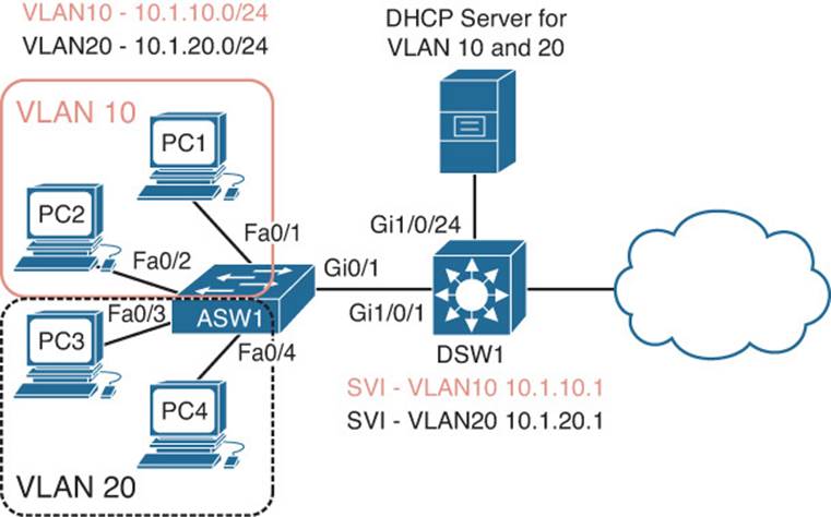
Figure 7-2 Spoof-Prevention Features Trouble Ticket Topology
Trouble Ticket 7-2
Problem: A junior administrator has approached you for assistance with a trouble ticket that she is having an issue with. The trouble ticket indicates that users in VLAN 10 are not able to access any resources outside their own subnet. They have verified that the clients receive their IP addressing information via a DHCP server. However, they are confused as to why they would be receiving the default gateway address of 10.1.10.100 when documentation shows that the default gateway should be configured as 10.1.10.1. They also indicate that they verified the DHCP pool on the DHCP server and that the default gateway address for the VLAN 10 pool is configured for 10.1.10.1.
To assist with the issue, you decide to connect your laptop to Fast Ethernet 0/24 on ASW1. This is the port on ASW1 that is used as the Switched Port Analyzer (SPAN) destination port. You configure ASW1, as shown in Example 7-33, so that all traffic sent or received by Fa0/1 is captured and sent to Fa0/24, where your laptop is connected and running packet-capturing software.
Example 7-33 Configuring a SPAN Session on ASW1
ASW1#config t
Enter configuration commands, one per line. End with CNTL/Z.
ASW1(config)#monitor session 1 source interface fastEthernet 0/1 both
ASW1(config)#monitor session 1 destination interface fastEthernet 0/24
You access PC1 and issue the ipconfig /renew command to trigger the DHCP process so that you can identify who is providing the IP addressing. The DHCP packets between the server and PC1 are successfully copied by SPAN to your laptop running packet-capturing software, which is connected to Fa0/24.
You review the DHCP offer message in your packet-capture software and notice that it is sourced from IP 10.1.10.34 and MAC 28:93:fe:3a:e3:45. Using the show mac address-table dynamic address 28:93:fe:3a:e3:45 command to follow the path, as shown in Example 7-34, you verify that the device with that MAC address is reachable out Fa0/17, which is part of VLAN 10. You review your network documentation and trace the port to a PC that is being used for study purposes by an employee that currently enabled DHCP and just happened to use the same network that VLAN 10 is using in the production network. You ask the employee to disable the DHCP server, and she does.
Example 7-34 Renewing a DHCP Address
ASW1#show mac address-table dynamic address 28:93:fe:3a:e3:45
Mac Address Table
-------------------------------------------
Vlan Mac Address Type Ports
---- ----------- -------- -----
10 28:93:fe:3a:e3:45 DYNAMIC Fa0/17
Total Mac Addresses for this criterion: 1
The issue is solved. To update all the client PCs, you issue the ipconfig /renew command on all of them. They receive the correct default gateway of 10.1.10.1 now. However, you decide to dig deeper. Your network is configured with DHCP snooping, DAI, and IP Source Guard. As a result, this issue should have never happened. You decide to issue the show ip dhcp snooping command on ASW1 to verify the DHCP snooping configuration, as shown in Example 7-35. Based on the output, DHCP snooping is enabled globally, it is enabled for VLAN 20, information option 82 is disabled, and Gig0/1 is trusted. You have identified the problem. DHCP snooping has not been enabled for VLAN 10. Therefore, the DHCP server that was configured on Fa0/17 is able to hand out DHCP addresses on the network. By your enabling of DHCP snooping for VLAN 10, Fa0/17 would become an untrusted port by default and prevent DHCP Offer and Acks from being accepted inbound.
Example 7-35 Reviewing the DHCP Snooping Configuration
ASW1#show ip dhcp snooping
Switch DHCP snooping is enabled
DHCP snooping is configured on following VLANs:
20
DHCP snooping is operational on following VLANs:
20
DHCP snooping is configured on the following L3 Interfaces:
Insertion of option 82 is disabled
circuit-id default format: vlan-mod-port
remote-id: 001c.57fe.f600 (MAC)
Option 82 on untrusted port is not allowed
Verification of hwaddr field is enabled
Verification of giaddr field is enabled
DHCP snooping trust/rate is configured on the following Interfaces:
Interface Trusted Allow option Rate limit (pps)
----------------------- ------- ------------ ----------------
GigabitEthernet0/1 yes yes unlimited
Custom circuit-ids:
To fix the DHCP snooping configuration, you issue the ip dhcp snooping vlan 10 command in global configuration mode, as shown in Example 7-36.
Example 7-36 Configuring DHCP Snooping for VLAN 10
ASW1#config t
Enter configuration commands, one per line. End with CNTL/Z.
ASW1(config)#ip dhcp snooping vlan 10
You verify the configuration with the show ip dhcp snooping command again and confirm that VLAN 10 is now enabled for DHCP snooping, as shown in Example 7-37.
Example 7-37 Verifying DHCP Snooping Is Enabled for VLAN 10
ASW1#show ip dhcp snooping
Switch DHCP snooping is enabled
DHCP snooping is configured on following VLANs:
10,20
DHCP snooping is operational on following VLANs:
10,20
DHCP snooping is configured on the following L3 Interfaces:
Insertion of option 82 is disabled
circuit-id default format: vlan-mod-port
remote-id: 001c.57fe.f600 (MAC)
Option 82 on untrusted port is not allowed
Verification of hwaddr field is enabled
Verification of giaddr field is enabled
DHCP snooping trust/rate is configured on the following Interfaces:
Interface Trusted Allow option Rate limit (pps)
----------------------- ------- ------------ ----------------
GigabitEthernet0/1 yes yes unlimited
Custom circuit-ids:
Troubleshooting Access Control
Access control between devices within the same VLAN/subnet can be implemented using features such as protected ports, private VLANs, and VLAN access control lists (VACLs). Because the devices are in the same VLAN/subnet that you are trying to filter traffic to or from, regular router-based ACLs that are applied to router interfaces will not filter this traffic. This is because that traffic is never sent to the router interface. It stays within the local subnet/VLAN between the Layer 2 switchports.
This section explains what is involved when troubleshooting issues related to protected ports, private VLANs, and VACLs, which are used to filter traffic between devices within the same subnet/VLAN.
Protected Ports
The purpose of a protected port is to deny all traffic from flowing between devices connected to two interfaces in the same VLAN on the same switch. Therefore, when troubleshooting protected ports, you are usually dealing with the following issues:
![]() Traffic is flowing between two interfaces when it should not be.
Traffic is flowing between two interfaces when it should not be.
![]() Traffic is not flowing between two interfaces when it should be.
Traffic is not flowing between two interfaces when it should be.
When dealing with protected ports, both these issues would be the result of a misconfiguration. Keep in mind that a protected port can only communicate with ports that are not protected ports. If traffic arrives inbound on a protected port, it will not be forwarded if the egress port is also a protected port. Therefore, if two devices are able to communicate when they should not, it might be because one port is a protected port and the other is not a protected port when it should be.
Figure 7-3 displays an access layer switch with PC1 and PC2 connected to it on Fa0/1 and Fa0/2. Both ports are members of VLAN 10. However, for security reasons, traffic is not allowed to flow between Fa0/1 and Fa0/2. Example 7-38 displays the interface configuration commandswitchport protected that is used to configure the ports as protected.
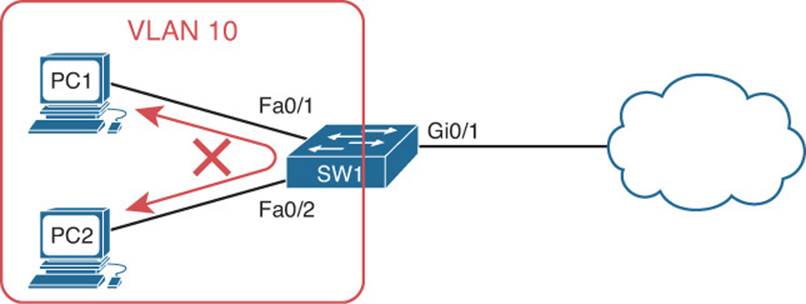
Figure 7-3 Protected Ports
Example 7-38 Sample Protected Port Configuration
SW1#show run interface fastEthernet 0/1
...output omitted...
interface FastEthernet0/1
switchport access vlan 10
switchport mode access
switchport protected
end
SW1#show run interface fastEthernet 0/2
...output omitted...
interface FastEthernet0/2
switchport access vlan 10
switchport mode access
switchport protected
end
Besides using the running configuration to verify protected ports, you can use the command show interfaces interface_type interface_number switchport to verify whether a port is configured as a protected port, as shown in Example 7-39. In the output for Fa0/1, it states Protected: true, which means Fa0/1 is a protected port.
Example 7-39 Verifying Protected Ports
SW1#show interfaces fastEthernet 0/1 switchport
Name: Fa0/1
Switchport: Enabled
Administrative Mode: static access
Operational Mode: static access
Administrative Trunking Encapsulation: dot1q
Operational Trunking Encapsulation: native
Negotiation of Trunking: Off
Access Mode VLAN: 10 (10.1.1.0/26)
Trunking Native Mode VLAN: 1 (default)
Administrative Native VLAN tagging: enabled
Voice VLAN: none
Administrative private-vlan host-association: none
Administrative private-vlan mapping: none
Administrative private-vlan trunk native VLAN: none
Administrative private-vlan trunk Native VLAN tagging: enabled
Administrative private-vlan trunk encapsulation: dot1q
Administrative private-vlan trunk normal VLANs: none
Administrative private-vlan trunk associations: none
Administrative private-vlan trunk mappings: none
Operational private-vlan: none
Trunking VLANs Enabled: ALL
Pruning VLANs Enabled: 2-1001
Capture Mode Disabled
Capture VLANs Allowed: ALL
Protected: true
Unknown unicast blocked: disabled
Unknown multicast blocked: disabled
Appliance trust: none
Private VLANs
Private VLANs (PVLAN) take the protected port concept further by enabling you to control which ports in the same VLAN can communicate with each other and which ports cannot. This is accomplished by grouping ports together in secondary VLANs that are members of a Private VLAN. Just like protected ports, when troubleshooting PVLANs, you are usually dealing with the following issues:
![]() Traffic is flowing between two interfaces when it should not be.
Traffic is flowing between two interfaces when it should not be.
![]() Traffic is not flowing between two interfaces when it should be.
Traffic is not flowing between two interfaces when it should be.
When dealing with PVLANs, both these issues would be the result of a misconfiguration. Refer to Figure 7-4, which will be used for our PVLAN examples. DNS1 and DNS2 are in the secondary community VLAN of 501, which is within the primary VLAN 200. FS1 and FS2 are in the secondary isolated VLAN 502, which is within the primary VLAN 200. Therefore, based on the rules of PVLANs, the following are true:
![]() DNS1 and DNS2 are able to communicate with each other because they are members of the same community VLAN.
DNS1 and DNS2 are able to communicate with each other because they are members of the same community VLAN.
![]() DNS1 and DNS2 are not able to communicate with FS1 and FS2 because DNS1 and DNS2 are members of a community VLAN and FS1 and FS2 are members of an isolated VLAN.
DNS1 and DNS2 are not able to communicate with FS1 and FS2 because DNS1 and DNS2 are members of a community VLAN and FS1 and FS2 are members of an isolated VLAN.
![]() FS1 and FS2 are not able to communicate with each other because they are members of an Isolated VLAN.
FS1 and FS2 are not able to communicate with each other because they are members of an Isolated VLAN.
![]() DNS1, DNS2, FS1, and FS2 are able to communicate out to the cloud because Gi1/0/10 is the promiscuous port.
DNS1, DNS2, FS1, and FS2 are able to communicate out to the cloud because Gi1/0/10 is the promiscuous port.
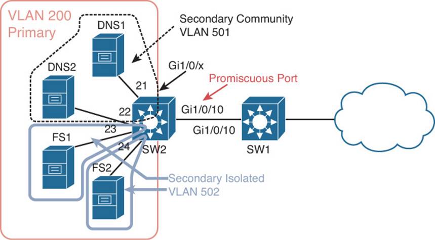
Figure 7-4 PVLANs
To successfully troubleshoot PVLANs, you need to remember the following PVLAN rules:
![]() Community ports can communicate with other community ports in the same community.
Community ports can communicate with other community ports in the same community.
![]() Community ports cannot communicate with other community ports in a different community.
Community ports cannot communicate with other community ports in a different community.
![]() Community ports cannot communicate with isolated ports and vice versa.
Community ports cannot communicate with isolated ports and vice versa.
![]() Isolated ports cannot communicate with other isolated ports.
Isolated ports cannot communicate with other isolated ports.
![]() Community and isolated ports can communicate with the promiscuous port.
Community and isolated ports can communicate with the promiscuous port.
Example 7-40 displays the commands required to successfully implement the PVLANs in Figure 7-4. First, unless you are using Virtual Trunking Protocol (VTP) Version 3, the VTP mode has to be transparent or off. VTP Versions 1 and 2 cannot carry PVLAN information like VTPv3. The primary VLAN needs to be identified with the private-vlan primary command and associated with the secondary VLANs with the private-vlan association command. In addition, the secondary community VLAN needs to be identified with the private-vlan community command, and the secondary isolated VLAN needs to be identified with the private-vlan isolated command. After the VLANs have been identified, you can associate the ports on the switch with the appropriate VLANs. In this example, Gig1/0/10 is the promiscuous port for the secondary VLANs 501 and 502 that are mapped to the primary VLAN 200, as identified by the commands switchport private-vlan mapping 200 501-502 and switchport mode private-vlan promiscuous. To associate a port with a secondary VLAN, you use the switchport private-vlan host-association primary_vlan secondary_vlan command in interface configuration mode along with the command switchport mode private-vlan host. The only way to determine from this output that the interface is in the correct secondary VLAN is to examine the switchport private-vlan host-associationprimary_vlan secondary_vlan command and compare the secondary VLAN ID to the VLAN configuration information. For example, if you compare the secondary VLAN ID of 502 in the command switchport private-vlan host-association 200 502 of interface Gig1/0/23 with the VLAN 502 configuration, you will notice that VLAN 502 is an isolated VLAN.
Example 7-40 PVLAN Configuration Example
SW2#show run
...output omitted...
!
vtp mode transparent
!
vlan 200
private-vlan primary
private-vlan association 501-502
!
vlan 501
private-vlan community
!
vlan 502
private-vlan isolated
!
...output omitted...
!
interface GigabitEthernet1/0/10
switchport private-vlan mapping 200 501-502
switchport mode private-vlan promiscuous
!
...output omitted...
!
interface GigabitEthernet1/0/21
switchport private-vlan host-association 200 501
switchport mode private-vlan host
!
interface GigabitEthernet1/0/22
switchport private-vlan host-association 200 501
switchport mode private-vlan host
!
interface GigabitEthernet1/0/23
switchport private-vlan host-association 200 502
switchport mode private-vlan host
!
interface GigabitEthernet1/0/24
switchport private-vlan host-association 200 502
switchport mode private-vlan host
!
...output omitted...
end
As you can see, with all the different parameters, it is very easy to misconfigure PVLANs. Therefore, it is imperative that you can read a PVLAN configuration, compare it to a topological diagram, and determine where the misconfiguration is that is causing traffic to be forwarded to ports it should not be forwarded to or causing traffic to not be forwarded to ports it should be forwarded to.
In addition, you can verify the private VLANs and the ports associated with each private VLAN using the show vlan private-vlan command, as shown in Example 7-41. You can see in this output the primary VLAN 200 and its associated community VLAN 501 and isolated VLAN 502. The ports associated with the community VLAN are Gi1/0/10, Gi1/0/21, and Gi1/0/22. The ports associated with the isolated VLAN are Gi1/0/10, Gi1/0/23, and Gi1/0/24. The first port, Gi1/0/10, is the promiscuous port in both cases.
Example 7-41 Verifying Private VLANs and Associated Ports
SW2#show vlan private-vlan
Primary Secondary Type Ports
------- --------- ----------------- ------------------------------------------
200 501 community Gi1/0/10, Gi1/0/21, Gi1/0/22
200 502 isolated Gi1/0/10, Gi1/0/23, Gi1/0/24
You can also use the command show interfaces interface_type interface_number switchport to verify the PVLAN status and configuration of a specific interface. As shown in Example 7-42, the administrative mode and operational mode is private-vlan host, indicating that it is either a member of a community vlan or isolated vlan. If it stated private-vlan promiscuous, it is the promiscuous port. The primary VLAN in this case is VLAN 200, as indicated by the line Access Mode VLAN: 200 (primary). Further down, you can see the host association, which indicates that the primary VLAN is VLAN 200 and that this specific port is a member of the secondary VLAN 501. In addition, the Operational private-vlan output states the same.
Example 7-42 Verifying Private VLAN Information for a Specific Port
SW2#show interfaces gigabitEthernet 1/0/22 switchport
Name: Gi1/0/22
Switchport: Enabled
Administrative Mode: private-vlan host
Operational Mode: private-vlan host
Administrative Trunking Encapsulation: negotiate
Operational Trunking Encapsulation: native
Negotiation of Trunking: Off
Access Mode VLAN: 200 (primary)
Trunking Native Mode VLAN: 1 (default)
Administrative Native VLAN tagging: enabled
Voice VLAN: none
Administrative private-vlan host-association: 200 (10.1.200.0/24) 501 (VLAN0501)
Administrative private-vlan mapping: none
Administrative private-vlan trunk native VLAN: none
Administrative private-vlan trunk Native VLAN tagging: enabled
Administrative private-vlan trunk encapsulation: dot1q
Administrative private-vlan trunk normal VLANs: none
Administrative private-vlan trunk associations: none
Administrative private-vlan trunk mappings: none
Operational private-vlan:
200 (10.1.200.0/24) 501 (VLAN0501)
...output omitted...
VACLs
Protected ports and PVLANs are excellent features that help you control the traffic that can flow between ports in the same subnet/VLAN. However, they lack granular control. Therefore, it is all traffic or no traffic that is being forwarded between the ports. You cannot pick which type of traffic to control. If you do need to control the type of traffic that is flowing between ports in the same VLAN/subnet on a switch, you can implement VLAN access control lists (VACLs). Because you are able to control traffic on a more granular level, when troubleshooting VACLs you need to examine a few different components that make up the VACL:
![]() ACLs: Used to define the traffic that will be examined by the VLAN access map (IP or MAC). Use the show access-lists command to verify the configured ACLs.
ACLs: Used to define the traffic that will be examined by the VLAN access map (IP or MAC). Use the show access-lists command to verify the configured ACLs.
![]() VLAN access map: Used to define the action that will be taken on the traffic that is matched in the ACLs. Use the show run | section vlan access-map command or the show vlan access-map command to verify the configured VLAN access maps.
VLAN access map: Used to define the action that will be taken on the traffic that is matched in the ACLs. Use the show run | section vlan access-map command or the show vlan access-map command to verify the configured VLAN access maps.
![]() VLAN filter list: Used to define which VLANs the VLAN access map will apply to. Use the show run | include vlan filter command or the show vlan filter command to verify the configured VLAN filter list.
VLAN filter list: Used to define which VLANs the VLAN access map will apply to. Use the show run | include vlan filter command or the show vlan filter command to verify the configured VLAN filter list.
Refer to the sample VACL in Example 7-43, which was used to configure SW1 in Figure 7-5. This VACL is designed to prevent PC1 from being able to ping or telnet to PC2, which is in the same VLAN. However, PC1 will be able to access other resources and services on PC2. Notice all the different configurations that could cause the VACL to not function as expected.
![]() The ACL could be misconfigured: Permit versus deny, wrong protocol, wrong addresses, wrong ports.
The ACL could be misconfigured: Permit versus deny, wrong protocol, wrong addresses, wrong ports.
![]() The VLAN access map could be in the wrong sequence order: Just like an ACL, route map, and prefix list, it uses top-down processing, will immediately execute the actions upon a match, and there is an implicit deny all at the end.
The VLAN access map could be in the wrong sequence order: Just like an ACL, route map, and prefix list, it uses top-down processing, will immediately execute the actions upon a match, and there is an implicit deny all at the end.
![]() The VLAN access map could be misconfigured: Matching the wrong ACL, the action could be incorrect, such as drop versus forward.
The VLAN access map could be misconfigured: Matching the wrong ACL, the action could be incorrect, such as drop versus forward.
![]() The VLAN filter could be misconfigured: The filter may be referencing the wrong VLAN access map, it could be configured with the wrong VLAN list, or it may be missing completely.
The VLAN filter could be misconfigured: The filter may be referencing the wrong VLAN access map, it could be configured with the wrong VLAN list, or it may be missing completely.
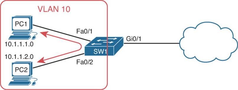
Figure 7-5 VACL
Example 7-43 Sample VLAN ACL Configuration
SW1#show access-lists
Extended IP access list 100
10 permit icmp host 10.1.1.10 host 10.1.1.20
20 permit tcp host 10.1.1.10 host 10.1.1.20 eq telnet
SW1#show run | section vlan access-map
vlan access-map TSHOOT 10
match ip address 100
action drop
vlan access-map TSHOOT 20
action forward
SW1#show run | include vlan filter
vlan filter TSHOOT vlan-list 10
Exam Preparation Tasks
As mentioned in the section “How to Use This Book” in the Introduction, you have a couple of choices for exam preparation: the exercises here; Chapter 22, “Final Preparation;” and the exam simulation questions on the CD-ROM.
Review All Key Topics
Review the most important topics in this chapter, noted with the Key Topic icon in the outer margin of the page. Table 7-2 lists a reference of these key topics and the page numbers on which each is found.
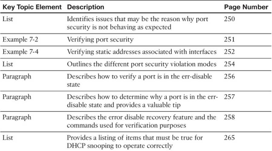
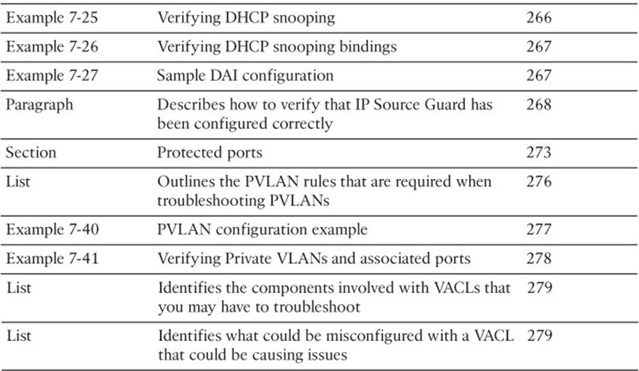
Table 7-2 Key Topics for Chapter 7
Define Key Terms
Define the following key terms from this chapter and check your answers in the glossary:
port security
protect violation mode
restrict violation mode
shutdown violation mode
err-disabled
sticky secure MAC address
DCHP snooping
DHCP snooping (trusted port)
DHCP snooping (untrusted port)
dynamic ARP inspection
IP Source Guard
protected ports
private VLANs
primary VLAN
community VLAN
isolated VLAN
promiscuous port
VLAN access control list
Command Reference to Check Your Memory
This section includes the most important show commands covered in this chapter. It might not be necessary to memorize the complete syntax of every command, but you should be able to remember the basic keywords that are needed.
To test your memory of the commands, cover the right side of Table 7-3 with a piece of paper, read the description on the left side, and then see how much of the command you can remember.
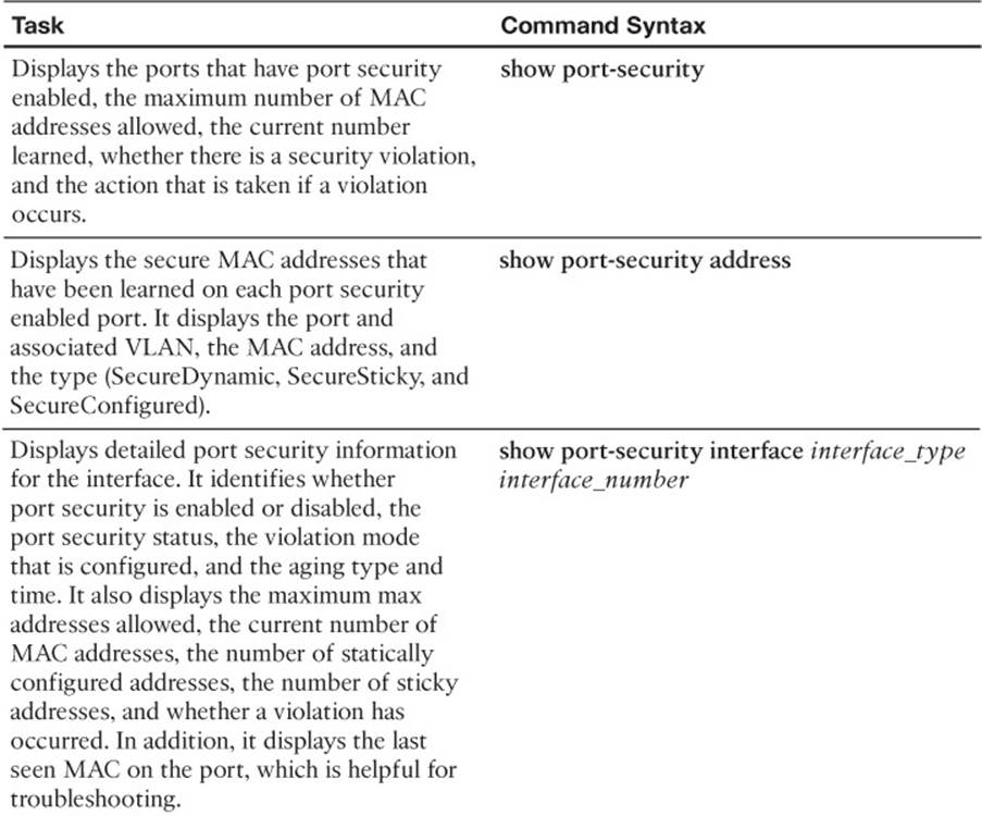
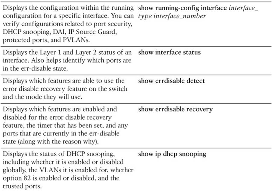
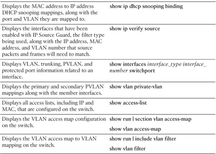
Table 7-3 show Commands Used for Verification and Troubleshooting
The 300-135 TSHOOT exam focuses on practical, hands-on skills that are used by a networking professional. Therefore, you should be able to identify the commands needed to successfully verify and troubleshoot the topics covered within this chapter.
All materials on the site are licensed Creative Commons Attribution-Sharealike 3.0 Unported CC BY-SA 3.0 & GNU Free Documentation License (GFDL)
If you are the copyright holder of any material contained on our site and intend to remove it, please contact our site administrator for approval.
© 2016-2026 All site design rights belong to S.Y.A.