CCNP Security SISAS 300-208 Official Cert Guide (2015)
Part IV: Implementing Secure Network Access
Chapter 15. Profiling
This chapter covers the following exam topics:
![]() Enable the profiling services
Enable the profiling services
![]() Network probes
Network probes
![]() IOS Device Sensor
IOS Device Sensor
![]() Feed service
Feed service
![]() Profiling policy rules
Profiling policy rules
![]() Utilize profile assignment in authorization policies
Utilize profile assignment in authorization policies
![]() Verify profiling operation
Verify profiling operation
There is often a lot of confusion about the difference between profiling and posture, and the terms can get mixed up. In Chapter 6, “Introduction to Advanced Concepts,” you were exposed to both technologies. Profiling is the technology used to determine what a device appears to be from an external perspective, whereas posture is the technology used to perform an internal examination of the system and report the facts. Posture is covered more in Chapter 19, “Posture Assessment.”
Profiling is used to build a database of endpoints that are on the network and assign them to a category based on their external attributes. Although profiling started out as a technology used to automate MAC Authentication Bypass (MAB), it has since morphed into an integral part of access control policy.
“Do I Know This Already?” Quiz
The “Do I Know This Already?” quiz enables you to assess whether you should read this entire chapter thoroughly or jump to the “Exam Preparation Tasks” section. If you are in doubt about your answers to these questions or your own assessment of your knowledge of the topics, read the entire chapter. Table 15-1 lists the major headings in this chapter and their corresponding “Do I Know This Already?” quiz questions. You can find the answers in Appendix A, “Answers to the ‘Do I Know This Already?’ Quizzes.”
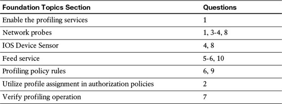
Table 15-1 “Do I Know This Already?” Section-to-Question Mapping
Caution
The goal of self-assessment is to gauge your mastery of the topics in this chapter. If you do not know the answer to a question or are only partially sure of the answer, you should mark that question as wrong for purposes of the self-assessment. Giving yourself credit for an answer you correctly guess skews your self-assessment results and might provide you with a false sense of security.
1. True or False? The profiling service is enabled by default on ISE policy service nodes.
a. True
b. False
2. Name three ways in which an endpoint profile can be used in an authorization policy rule?
a. Logical profiles
b. Endpoint identity groups
c. NMAP OS-Scan result
d. EndPointPolicy attribute
e. EndPointProfile attribute
3. Which probe is used to trigger the SNMPQUERY probe to query a NAD?
a. RADIUS
b. SNMPQUERY
c. HTTP
d. SNMPTRAP
e. Both A and D
f. Both C and D
4. Which three probes exist with device sensor?
a. CDP, DHCP, RADIUS
b. HTTP, CDP, RADIUS
c. CDP, DHCP, LLDP
d. CDP, HTTP, SNMP
5. How are updated profiles distributed to customer ISE deployments?
a. Cisco’s Profiler Feed Service.
b. Each new version of ISE or ISE patch includes new profile policies.
c. The profiles are distributed together with the posture checks and compliance modules.
d. Import the update packs that are downloaded from Cisco.com.
6. What determines when an endpoint is assigned to a profile?
a. The profile that matches the most conditions will be assigned.
b. All profiles are manually assigned by the administrator.
c. The certainty value must equal or exceed the minimum certainty value of the profile.
d. The ISE posture agent will identify the profile of an endpoint to ISE.
7. Which ISE tool enables an administrator to drill down in to the profiles that have been assigned to locate a specific endpoint with that profile?
a. Endpoints Drill-down
b. Cisco Endpoint Profiling Examination Tool (CEPET)
c. Profiled Endpoints Counter
d. Profiler Activity Window
8. What are two ways to collect HTTP user agent strings?
a. Through the AnyConnect HTTP User Agent Reporting Tool
b. SPAN port mirroring
c. The Cisco WSA device sensor
d. Directly from ISE web portals
e. Device sensor in the switch
9. True or False? ISE deployments must wait for Feed Service updates for new profiles.
a. True
b. False
10. What will happen when an ISE administrator has modified a profile and then a Feed Service update is downloaded that contains an updated version of that profile?
a. The profile is overwritten with the version in the Feed Service Update.
b. The admin will be prompted to choose to overwrite or ignore the profile update.
c. All nonconflicting profiles will be downloaded and installed. The conflicting profiles will be ignored.
d. The update will fail and an alarm will be triggered on the dashboard and in email.
Foundation Topics
ISE Profiler
The Cisco ISE Profiler is the component of the Cisco Identity Services Engine (ISE) platform that is responsible for endpoint detection and classification. It does so by using a probe or series of probes that collect attributes about an endpoint. The profiler then compares the collected attributes to predefined device signatures to locate a match.
In the early days of identity-based networks and 802.1X, countless hours were spent identifying all the devices that did not have supplicants—in other words, the devices that could not authenticate to the network using 802.1X, such as printers and fax machines. Your choices were to identify the port connected to the printer and configure it to either
![]() Not use 802.1X
Not use 802.1X
![]() Use MAC Authentication Bypass (MAB)
Use MAC Authentication Bypass (MAB)
MAB is an extension to 802.1X that enables the switch to send the device’s MAC address to the authentication server. If that MAC address is on the approved list of devices, the authentication server sends an “accept” result, therefore enabling specific MAC addresses to bypass authentication.
Countless hours were spent collecting and maintaining this list of MAC addresses. A manual onboarding procedure would eventually be created, so that when a new printer (or other valid device) was added to the network, its MAC address was added to the list.
Obviously, some enhancements to this manual process were required. There had to be some way to build this list more dynamically and save all those hours of preparation and maintenance.
As described in Chapter 6, this is where profiling technology enters the picture. It enables you to collect attributes about devices from sources such as DHCP, NetFlow, HTTP User-Agent strings, and more. Those collected attributes are then compared to a set of signatures, similar to the way an intrusion prevention system (IPS) works. These signatures are commonly referred to as profiles.
An example is collecting a MAC address that belongs to Apple, seeing that the HTTP User-Agent string contains the word “iPad,” and therefore assigning that device to the profile of “Apple-iPad.”
Profiling technology has evolved, as technology tends to do. Now your authentication server (ISE) has the ability to use that profiling data for much more than just building the MAB list.

Cisco’s Identity Services Engine uses the resulting collection and classification data from the profiler as conditions in the authorization policy. Now you can build an authorization policy that looks at much more than your identity credentials. We can combine a user’s identity with the classification result and invoke specific authorization results.
Figures 15-1 and 15-2 are examples of a differentiated authorization policy based on profiling.
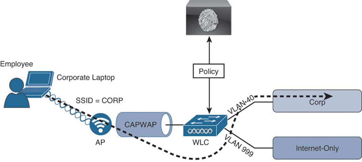
Figure 15-1 Employee using corporate laptop gains full access.
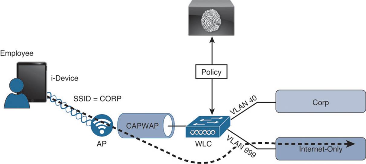
Figure 15-2 The same employee credentials on an i-device will get limited access.
Users who are using the same wireless SSID and the same credentials can be associated to different wired virtual local area network (VLAN) interfaces based on the device profile:
![]() Any employee using a corporate laptop with her Active Directory user ID is assigned to the corporate VLAN and given full access to the network.
Any employee using a corporate laptop with her Active Directory user ID is assigned to the corporate VLAN and given full access to the network.
![]() Any employee using an i-device with her same Active Directory user ID is assigned to a GUEST VLAN and provided Internet access only.
Any employee using an i-device with her same Active Directory user ID is assigned to a GUEST VLAN and provided Internet access only.
While it can be quite intuitive to visualize the types of network access policies you will be able to create based on the device’s profile, the design of where and how the profiler collects the data about the endpoints requires thought and planning.
One of the first questions a security team might ask when discussing profiling with any network access control solutions is “Can we use this as an antispoofing solution?” Remember that MAC Authentication Bypass (MAB) is really a very limited replacement for a strong authentication. It would be fairly easy for a malicious user to unplug a printer from the wall, configure his laptop to use the same MAC address as the printer (spoofing), and gain access to the network.
It is key to always keep in mind that profiling is a technology that compares collected attributes about an endpoint to a set of signatures called profiling policies to make the best guess of what a device is. Can this type of technology be used to prevent spoofing? Sure. However, it is difficult to accomplish antispoofing with this type of technology. It would require a lot of tuning, trial and error, and constant adjustment, which makes it too operationally expensive and untenable.
A best-practice approach is to use a least-privilege strategy instead. If the previously mentioned malicious user is successful in spoofing the MAC address of the printer and gains network access, what level of network access should that device have? In other words, the authorization policy for printers should not provide full network access, but should provide a very limited subset of access instead. So, a printer should be permitted to communicate using only network ports critical to printer operations (such as TCP port 9100 or 9600).
Cisco ISE Probes
As described previously, the Cisco Identity Services Engine solution is capable of providing access policies on which the decisions can be made based: who, what, where, when, how, and more. Profiling is focused on the “what” elements of the policy. For the policy engine to know what the device is, you must first collect that data.
The Cisco Identity Services Engine solution uses a number of collection mechanisms known as probes. The probe is software designed to collect data to be used in a profiling decision. An example of this is the HTTP Probe, which captures HTTP traffic and enables the profiler to examine attributes from the traffic, such as HTTP User-Agent strings.
Probe Configuration
You enable the probes on each policy service node (PSN) where appropriate. In the Administration GUI of the PSN, navigate to Administration > System > Deployment. From here, select the PSN for which you are configuring the probes. You must repeat these steps for each PSN in your deployment:
Step 1. Select one of the PSNs, as shown in Figure 15-3. In this case, the node is standalone, which means it is a single node running all personas (Admin, Monitoring, and Policy Service).
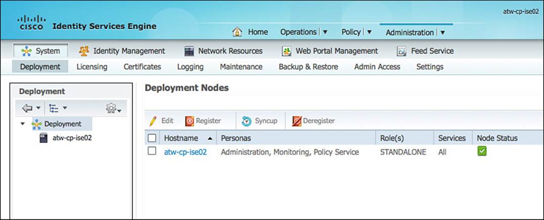
Figure 15-3 ISE Deployment screen.
Step 2. Ensure the Enable Profiling Service check box is selected. This service is enabled by default on all PSNs and is not configurable when in standalone mode, as shown in Figure 15-4.
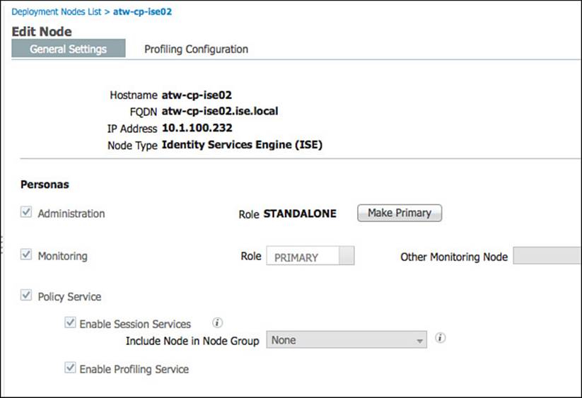
Figure 15-4 General settings.
Step 3. Select the Profiling Configuration tab, as shown in Figure 15-5.
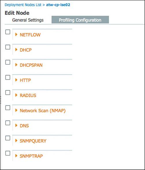
Figure 15-5 Profiling configuration.
There are nine probes on each PSN:
![]() NETFLOW
NETFLOW
![]() DHCP
DHCP
![]() DHCPSPAN
DHCPSPAN
![]() HTTP
HTTP
![]() RADIUS
RADIUS
![]() Network Scan (NMAP)
Network Scan (NMAP)
![]() DNS
DNS
![]() SNMPQUERY
SNMPQUERY
![]() SNMPTRAP
SNMPTRAP
Each probe will be examined in detail, but not in order.
DHCP and DHCPSPAN
DHCP can be one of the most useful data sources for an endpoint device. A primary use of DHCP in profiling is to capture the device MAC address; however, there are many other uses for the data. Much like HTTP, DHCP requests also carry a User-Agent field that helps to identify the operating system (OS) of the device. Some organizations have been known to use a custom DHCP User-Agent string, which helps to identify the device as a corporate asset.
Not only the populated fields from the DHCP client are useful in classification, but other attributes, such as requested DHCP options and the DHCP hostname, can also be helpful in further classifying the device.
Unlike HTTP, there are two DHCP probes, each working in a slightly different way: DHCP and DHCP SPAN.
DHCP
The DHCP probe requires the DHCP requests to be sent directly to the ISE PSN(s). This is often done by using the ip helper-address interface configuration command to forward the request to both the DHCP server and the PSN, as illustrated in Figure 15-6.
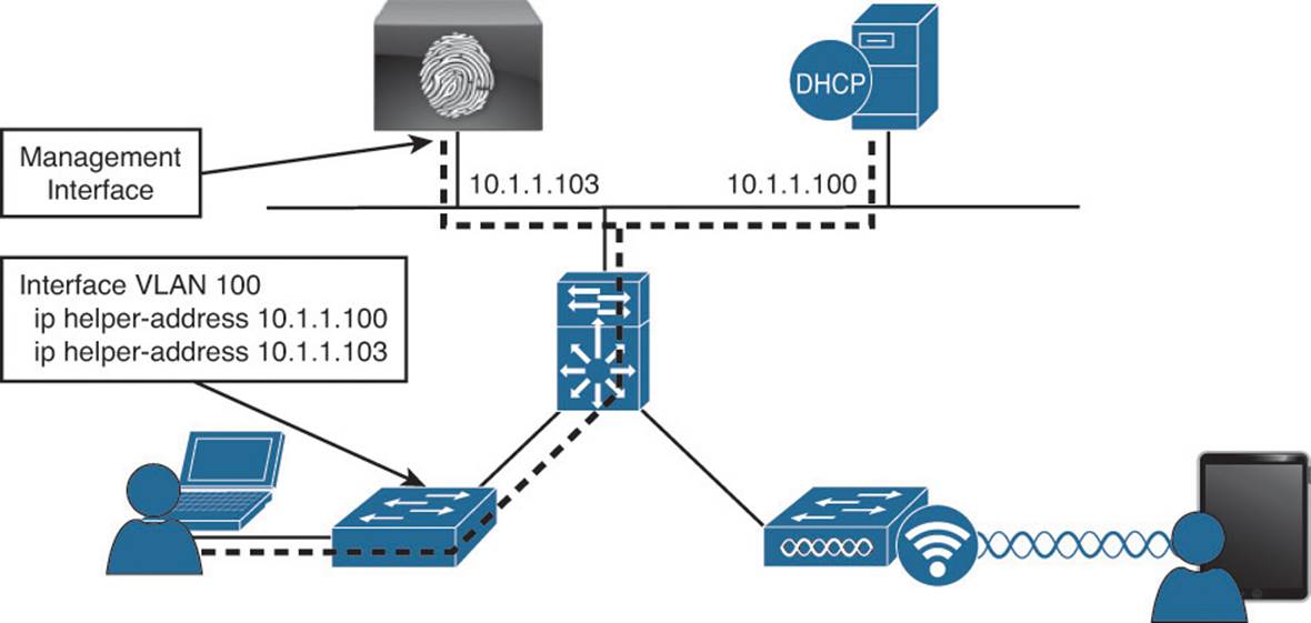
Figure 15-6 DHCP with ip helper-address logical design.
The ip helper-address command on a Layer-3 interface converts a DHCP broadcast (which is a Layer-2 broadcast) to a unicast or directed broadcast (which is sending the broadcast to all hosts on a specific subnet). Simply add the IP address of your PSN(s) to the list of helper addresses, and it will be copied on all DHCP requests. Not to worry, though—the Cisco Identity Services Engine server will never respond to that request. It will only use the incoming data to profile endpoints.
DHCPSPAN
Another way for ISE to glean the DHCP requests and even the DHCP responses is the use of Switched Port Analyzer (SPAN) session in true promiscuous mode. A SPAN session copies all traffic to/from a source interface on a switch to a destination interface, which would be one of ISE’s interfaces assigned to the DHCPSPAN probe. The logical design of using SPAN is illustrated in Figure 15-7.
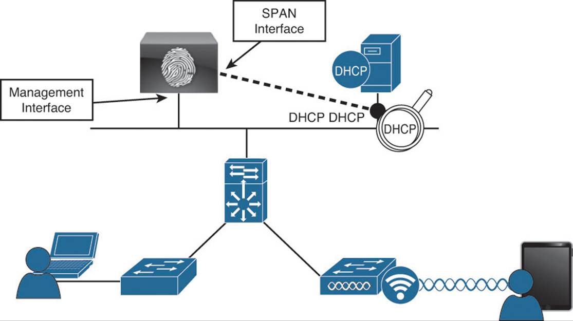
Figure 15-7 DHCP SPAN logical design.
When using the SPAN method, you need to consider where the best location is to create the SPAN session and gather the data. One recommended location is the DHCP server, where the DHCP probe will see both ends of the conversation (request and response). However, there are caveats to this method, such as: “What if the organization uses distributed DHCP servers?” This is why the non-SPAN method tends to be the most commonly deployed.
Considerations with the Cisco WLC
It is important to note that regardless of the SPAN or helper address methods of using the DHCP probe(s), when using a Wireless LAN Controller (WLC), the WLC has a default configuration of acting as a RADIUS proxy, which is its own form of a helper address where the WLC acts as a middle man for all DHCP transactions. Unfortunately, this behavior will have a negative effect on the DHCP probe and must be disabled on the WLC. Upon doing so, the DHCP requests from wireless endpoints will appear as broadcast messages on the VLAN, and an ip helper-address statement should be configured on the Layer-3 interface of that VLAN (the switch or router).
Probe Configuration
Minimal configuration is required on the ISE side to enable the DHCP probe(s). From the Profiling Configuration tab displayed in Figure 15-5, do the following:
Step 1. Click the check box next to the DHCP and/or DHCP SPAN probe to enable them.
Step 2. Select either the Gigabit 0 interface or all interfaces. Multiple interfaces cannot be individually selected. The choices will be a single interface or all interfaces.
Figure 15-8 shows the DHCP probes. You should never need to enable both probes for the same interface. That would cause double processing of DHCP packets and be somewhat wasteful of system resources.
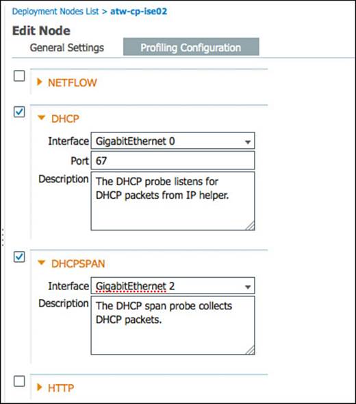
Figure 15-8 DHCP probes.
Note
If you are using only device sensor-capable infrastructure, neither DHCP probe needs to be enabled.
RADIUS
RADIUS is the primary communication mechanism from a network access device (NAD) to the authentication server (ISE). There is useful data to help you classify a device that exists within RADIUS communication.
Originally, this was focused on the MAC address and IP address of the device. By having this data conveyed in the RADIUS packet, ISE is capable of building the all-important MAC-to-IP address bindings. Because the endpoint database uses MAC addresses as the unique identifier for all endpoints, these bindings are absolutely critical. Without them, the Layer-3 probes such as HTTP and NMAP scanning would never work correctly.
The Calling-Station-ID field in the RADIUS packet provides the endpoint’s MAC address, and the Framed-IP-Address field provides its IP address in the RADIUS accounting packet.
Additionally, the RADIUS probe triggers the SNMPQUERY probe to poll the NAD (see the following SNMP probe information).
Most importantly, with the proliferation of device sensor-capable switches and wireless controllers, the RADIUS probe becomes even more critical. Device sensor is a feature in the switch or controller that collects endpoint attributes locally and then sends those attributes to ISE within RADIUS accounting packets.
By allowing the network device to proactively send the profiling data to ISE, the architecture has placed the collection agents as close to the endpoint as possible, at the point of access to the network. Additionally, it has eliminated the need to send the ip helper-address information to ISE as well as the need to reactively query the switches for CDP/LLDP information (see the section “SNMPQUERY”).
Considerations with RADIUS Probe
All NADs in the Secure Unified Access Deployment should be configured to send RADIUS accounting packets. It is also important to note that the Cisco switch must learn the endpoint’s IP address via DHCP snooping or ip-device-tracking to fill in the Framed-IP-Address field.
Probe Configuration
Minimal configuration is required on the ISE side to enable the RADIUS probe(s). From the Profiling Configuration tab displayed in Figure 15-5, just click the check box next to the RADIUS to enable the RADIUS probe, as shown in Figure 15-9.
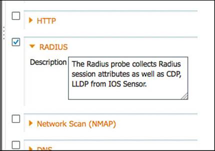
Figure 15-9 RADIUS probe.
Notice that configuration really isn’t possible with this probe. However, it is one of the most useful probes, especially when combined with device sensor.
Network Scan
A very welcome improvement to ISE version 1.1 is the addition of the endpoint scanning (NMAP) probe. NMAP is a tool that uses port scans, SNMP, and other mechanisms to identity a device’s OS or other attributes of the device. The NMAP probe can be manually run against a single IP address or subnet. More importantly, the profiler engine can be configured to react to a profiling event with a reactive NMAP probe.
For example, when an endpoint is discovered to be an “Apple-Device,” ISE automatically launches an NMAP OS scan against that endpoint to determine whether it is running MAC OSX or iOS. From the results of that scan, ISE further classifies the device as a MAC device or an i-device.
Considerations with the NMAP Probe
The Endpoint Scanning (NMAP) probe is executed against an IP Address or range of IP addresses. However, it is absolutely crucial to keep in mind that the endpoint database uses a MAC Address as the unique identifier of any endpoint. As such the Policy Services Node will rely on the MAC Address-to-IP Address binding to update an endpoint’s attributes with the results of the NMAP scan. Therefore it is absolutely critical that the PSN had received valid information from the other probes.
The NMAP probe can be manually run against a single IP-Address or subnet, or (more commonly) an NMAP scan can be triggered as an action of a profile.
Probe Configuration:
As with all the other probes, only minimal configuration is needed in the ISE GUI. From the Profiling Configuration tab displayed in Figure 15-5, just click the check box next to the Network Scan (NMAP) probe to enable it. You can also run a manual scan from this screen against a single node, or an entire network, as shown in Figure 15-10.
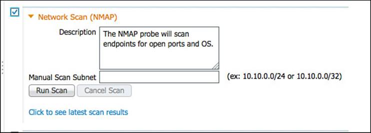
Figure 15-10 Network Scan (NMAP) probe.
DNS
The DNS probe is used to collect the fully qualified domain name (FQDN) of an endpoint using a reverse-lookup for the static or dynamic DNS registration of that endpoint. It is quite useful when looking for a specific DNS name format of corporate assets (Active Directory members).
A reverse DNS lookup will be completed only when an endpoint is detected by one of the DHCP, RADIUS, HTTP, and SNMP probes.
To enable the DNS probe, simply click the check box next to the DNS probe to enable it, as shown in Figure 15-11. This probe will use the name server configuration from the Identity Services Engine node itself.
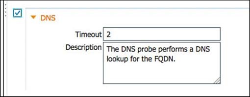
Figure 15-11 DNS probe.
SNMPQUERY and SNMPTRAP
SNMP is used to query NADs that do not yet support Cisco’s device sensor. After enabling the SNMPQUERY probe, ISE will poll all the SNMP-enabled NADs at the configured polling interval.
Note
It is recommended to remove SNMP settings from NADs that support IOS sensor to avoid double work and wasted processing.
There are two SNMP probes: SNMPQUERY and SNMPTRAP.
SNMPTRAP
The SNMP Trap receives information from the configured NAD(s) that support MAC notification, linkup, linkdown, and informs. The purpose of this probe is twofold: It is used to trigger the SNMPQUERY probe, and it is used as a toggle-switch to enable the SNMPQUERY probe to reactively query a NAD instead of waiting for the periodic polling interval. Therefore, for SNMPTRAP to be functional, you must also enable the SNMPQUERY probe.
The SNMPTRAP probe receives information from the specific NAD(s) when the MAC address table changes or when link state changes on a switch port. To make this feature functional, you must configure the NAD to send SNMP traps or informs.
SNMPQUERY
SNMPQUERY does the bulk of the work. There are three kinds of SNMPQUERY probes:
![]() System—The System probe polls all NADs that are configured for SNMP at the configured interval.
System—The System probe polls all NADs that are configured for SNMP at the configured interval.
![]() Interface—The Interface probe occurs in response to an SNMPTRAP or RADIUS Accounting start packet (only if the SNMPTRAP probe is enabled).
Interface—The Interface probe occurs in response to an SNMPTRAP or RADIUS Accounting start packet (only if the SNMPTRAP probe is enabled).
![]() Network Scan—The Network Scan (NMAP) probe triggers the SNMP walk of an endpoint.
Network Scan—The Network Scan (NMAP) probe triggers the SNMP walk of an endpoint.
When querying a NAD, ISE looks for interface data (which interface, which VLAN, and so on), session data (if the interface is Ethernet), Cisco Discovery Protocol (CDP) data, and Link Layer Discovery Protocol (LLDP) data. The CDP and LLDP data can be useful in identifying a device type by its registered capabilities and similar attributes.
Note
For distributed deployments, NAD polling is distributed among all PSNs enabled for SNMPQUERY probes.
Probe Configuration
When configuration to these probes is necessary, such as the trap types to examine and the SNMP port, it is recommended to leave these at their default settings unless directed otherwise by Cisco TAC. Do the following:
Step 1. Click the check box next to the SNMPQUERY and SNMPTRAP probes to enable them.
Step 2. For the SNMPTRAP probe, select either the Gigabit 0 interface or all interfaces. Multiple interfaces cannot be individually selected. The choices will be a single interface or all interfaces.
Figure 15-12 shows the enabling of the SNMP probes and their default settings.
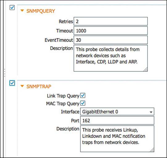
Figure 15-12 SNMP probes.
NETFLOW
NetFlow is an incredibly useful and undervalued security tool. Essentially, it is similar to a phone bill. A phone bill does not include recordings of all the conversations you have had in their entirety; instead it is a summary record of all calls sent and received.
Cisco routers and switches support NetFlow, sending a “record” of each packet that has been routed, including the ports and other useful information.
Just enabling NetFlow in your infrastructure and forwarding it all to the ISE can quickly oversubscribe your PSN. If you are planning to use the NetFlow probe, it is highly recommended that you have a third-party solution, such as LanCope StealthWatch, filter out any unnecessary data and only send what you truly need to ISE. For that reason, this probe is not focused on heavily in this exam or book, and it is recommended to perform extensive planning prior to its use.
Configuring the NetFlow probe is limited to enabling the check box next to the NetFlow probe and selecting either the Gigabit 0 interface or all interfaces. Figure 15-13 shows the enabled NetFLow probe.
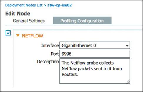
Figure 15-13 NetFlow probe.
HTTP Probe
When applications use HTTP, such as a web browser or even software such as Microsoft Outlook and Windows Update, it typically identifies itself and its application type, operating system, software vendor, and software revision by submitting an identification string to its operating peer. This information is transmitted in an HTTP request-header field called the User-Agent field.
The Cisco Identity Services Engine uses the information in HTTP packets; especially the User-Agent field, to help match signatures of what profile a device belongs in.
The two primary mechanisms for the HTTP probe to collect the HTTP traffic are as follows (see Figure 15-14):
![]() Use a Switched Port Analyzer (SPAN) session in true promiscuous mode. When using the SPAN method, you need to consider where the best place is to create the SPAN session and gather the data. One recommended location is the Internet Edge, where a network organization would typically deploy a Web Security Appliance such as the Cisco IronPort WSA.
Use a Switched Port Analyzer (SPAN) session in true promiscuous mode. When using the SPAN method, you need to consider where the best place is to create the SPAN session and gather the data. One recommended location is the Internet Edge, where a network organization would typically deploy a Web Security Appliance such as the Cisco IronPort WSA.
![]() Use a SPAN session in conjunction with a filter to limit the traffic visible to ISE. Another option to use with the SPAN design is the use of VLAN ACLs (VACLs) on a Catalyst 6500 or ACL-based SPAN sessions on a Nexus 7000. These options enable you to build an ACL that defines exactly what traffic you want to capture and send along to ISE—instead of a pure promiscuous SPAN, where the ISE interface will see all traffic. This is a better way to manage the resource utilization on your ISE server when available.
Use a SPAN session in conjunction with a filter to limit the traffic visible to ISE. Another option to use with the SPAN design is the use of VLAN ACLs (VACLs) on a Catalyst 6500 or ACL-based SPAN sessions on a Nexus 7000. These options enable you to build an ACL that defines exactly what traffic you want to capture and send along to ISE—instead of a pure promiscuous SPAN, where the ISE interface will see all traffic. This is a better way to manage the resource utilization on your ISE server when available.
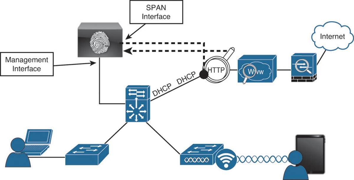
Figure 15-14 HTTP SPAN logical design.
As you can see, there are multiple ways to use the HTTP probe, and you should consider what works best for your environment and then deploy with that approach. In many environments, it is best to not use SPAN at all, but to leverage ISE’s own portals to capture the User-Agent strings.
To configure the HTTP probe, click the check box next to the HTTP probe, as shown in Figure 10-9. Select either the Gigabit 0 interface or all interfaces.
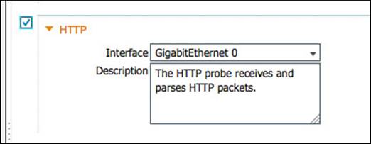
Figure 15-15 HTTP probe.
HTTP Profiling Without Probes
The Web Portal system within ISE has been outfitted to collect the user agent details from the web browser that is communicating with an ISE portal. This occurs regardless of profiling being enabled or not. The user agent is used to know which operating system is connecting and therefore which agent or client to send to the endpoint (in the cases of client and native supplicant provisioning).
When any portal collects that user agent, it is automatically passed over to the profiling engine within ISE, without requiring the HTTP probe to be enabled. It is a simple and efficient way to get the extremely valuable user agent string without having to rely on the computationally expensive SPAN methods.
Infrastructure Configuration
As an overall best practice, it is recommended to examine the cost benefit analysis of using processor-intensive probes or probe designs. For example, it is often recommended to use DHCP Helper instead of configuring a SPAN session and examining a multitude of traffic that might or might not be relevant.
Use HTTP traffic as an example. HTTP traffic is extremely useful for identifying the OS on a client endpoint; however, HTTP SPAN can consume a large amount of system resources on the PSN. Additionally, it might not be critical to have full visibility into the User-Agent strings of all devices, such as corporate-managed Windows devices.
Some deployments make use of VACL captures that can limit which traffic is sent to the SPAN session. Other deployments use the Authorization policy in ISE to send unknown devices to an ISE portal, enabling the portal to update the profiling data.
DHCP Helper
As previously shown in Figure 15-6, the ip helper-address commands are configured on the default gateway for each of the Access Layer VLANs. To configure the destination address to which to copy DHCP requests, enter interface configuration mode of the Layer-3 address for the VLAN and enter the ip helper-address [ip-address] command. You then must add the DHCP server and all applicable ISE PSNs to the list of helper address destinations.
Figure 15-16 shows sample output from a Layer-3 interface that is configured to send DHCP requests to the DHCP server in addition to two different ISE PSNs.
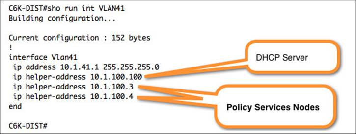
Figure 15-16 ip helper-address Settings.
SPAN Configuration
A monitor session is configured in global configuration mode and can be local (SPAN) or remote (RSPAN). Example 15-1 shows a SPAN configuration where an Internet-facing VLAN is the source of the session and an interface on the PSN is the destination. For more on SPAN configuration, see http://www.cisco.com/en/US/products/hw/switches/ps708/products_tech_note09186a008015c612.shtml.
Example 15-1 Monitor Session Command Input
DC-4948(config)#monitor session [1-4] source [interface | vlan] [rx | tx]
DC-4948(config)#monitor session [1-4] destination interface [interface_name]
Figure 15-17 shows the output of the show monitor command, where you can see the source and destination of the session.
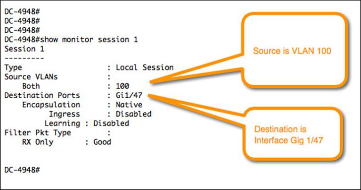
Figure 15-17 Sample monitor session (SPAN) configuration.
VLAN Access Control Lists
VACL configuration is a multistep process. It requires an access list to specify which traffic should be captured and another list to specify which traffic should be ignored. An access map must be configured to apply those ACLs to the traffic. The access map gets assigned to the VLAN(s), and finally you define the destination, like so:
Step 1. Build an access list to classify the traffic you want to capture, such as the one shown in Example 15-2.
Example 15-2 Creating an Access List to Match HTTP Traffic
C6K-DIST(config)#ip access-list extended HTTP_TRAFFIC
C6K-DIST(config-ext-nacl)#permit tcp any any eq www
Step 2. Build an access list for all the rest of the traffic, such as the one shown in Example 15-3.
Example 15-3 Creating an Access List to Match All Other Traffic
C6K-DIST(config)#ip access-list extended ALL_TRAFFIC
C6K-DIST(config-ext-nacl)#permit ip any any
Step 3. Create a VLAN access map sequence to capture HTTP traffic, such as what’s shown in Example 15-4.
Example 15-4 Creating a VLAN Access Map
C6K-DIST(config)#vlan access-map HTTP_MAP 10
C6K-DIST(config-access-map)#match ip address HTTP_TRAFFIC
C6K-DIST(config-access-map)#action forward capture
Step 4. Add a new sequence to the access map to forward all other traffic, such as what’s shown in Example 15-5.
Example 15-5 Adding Another Sequence to the Access Map
C6K-DIST(config)#vlan access-map HTTP_MAP 20
C6K-DIST(config-access-map)#match ip address ALL_TRAFFIC
C6K-DIST(config-access-map)#action forward
Step 5. Apply the VLAN access map to the VLAN list, as shown in Example 15-6.
Example 15-6 Applying the VLAN Access Map to the VLAN(s)
C6K-DIST(config)#vlan filter HTTP_MAP vlan-list 41,42
Step 6. Configure the destination port for the PSN’s SPAN interface, as shown in Example 15-7.
Example 15-7 Setting the Switchport Capture Destination
C6K-DIST(config)# interface gig1/0/1
C6K-DIST(config-if)#switchport capture allowed vlan 41
C6K-DIST(config-if)#switchport capture allowed vlan add 42
C6K-DIST(config-if)#switchport capture
Device Sensor
IOS device sensor requires a multipart configuration. The first part is to configure the device sensor filter lists. These lists inform device sensor of which items to consider important for each of the protocols.
The IOS device sensor supports three protocols: DHCP, CDP, and LLDP. Therefore, you must create one list for each protocol:
Step 1. Create a list for DHCP. You will need to configure three DHCP options for ISE: host-name, class-identifier, and client-identifier, as shown in Example 15-8.
Example 15-8 DHCP Filter List for Device Sensor
C3750X(config)#device-sensor filter-list dhcp list <dhcp_list_name>
C3750X(config-sensor-dhcplist)#option name host-name
C3750X(config-sensor-dhcplist)#option name class-identifier
C3750X(config-sensor-dhcplist)#option name client-identifier
Step 2. Create a list for CDP.
You will need to configure two CDP options for ISE: device-name and platform-type, as shown in Example 15-9.
Example 15-9 XDP Filter List for Device Sensor
C3750X(config)#device-sensor filter-list cdp list <cdp_list_name>
C3750X(config-sensor-cdplist)#tlv name device-name
C3750X(config-sensor-cdplist)#tlv name platform-type
Step 3. Create a list for LLDP:
You will need to configure three LLDP options for ISE: port-id, system-name, and system-description, as shown in Example 15-10.
Example 15-10 LLDP Filter List for Device Sensor
C3750X(config)#device-sensor filter-list lldp list <lldp_list_name>
C3750X(config-sensor-lldplist)#tlv name port-id
C3750X(config-sensor-lldplist)#tlv name system-name
C3750X(config-sensor-lldplist)#tlv name system-description
Step 4. Include the lists created in Steps 1-3 in the device sensor.
In the previous steps you defined the options that device sensor should store. At this point you will configure device sensor to use those lists, as shown in Example 15-11.
Example 15-11 Including the Protocol Lists in the Device Sensor
C3750X(config)#device-sensor filter-spec dhcp include list <dhcp_list_name>
C3750X(config)#device-sensor filter-spec lldp include list <cdp_list_name>
C3750X(config)#device-sensor filter-spec cdp include list <lldp_list_name>
Step 5. Enable the device sensor.
The device sensor is now configured. Next, you will enable the device sensor service to run on the switch and configure when it will send its updates, as shown in Example 15-12.
Example 15-12 Enable the Device Sensor to Notify of Changes
C3750X(config)#device-sensor accounting
C3750X(config)#device-sensor notify all-changes
VMware Configurations to Allow Promiscuous Mode
As shown in Figure 15-18, VMware vSwitches will reject promiscuous mode by default. To use SPAN-type probes with ISE, you must configure the vSwitch to allow promiscuous connections.
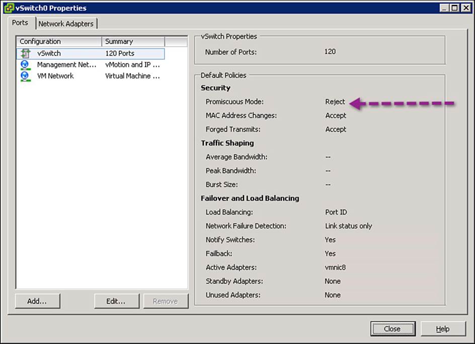
Figure 15-18 Default vSwitch configuration.
To modify the configuration and enable promiscuous traffic, do the following:
Step 1. Highlight the vSwitch and click Edit.
Step 2. Click on the Security tab.
Step 3. Change the Promiscuous Mode drop-down to Accept, as shown in Figure 15-19.
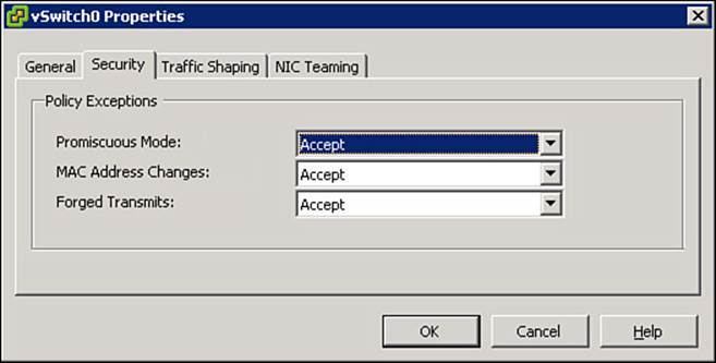
Figure 15-19 Promiscuous vSwitch setting.
Profiling Policies
Collecting the data for profiling is only part of the solution. The other aspects are to have endpoint signatures and a policy engine to compare the collected attributes to those signatures; this will lead to the assignment of the endpoint profile.
The profiling engine works a lot like an Intrusion Detection System (IDS), where traffic is compared to a set of signatures to identify suspicious activity. The profiling engine has hundreds of built-in signatures, called profiles, which are designed to match when certain attributes exist. Additionally, much like an IDS system, an update service enables the engine to download new signatures.
Profiler Feed Service
Although ISE comes with a large and comprehensive list of signatures to classify endpoints (profiles), many devices are produced almost daily (think of the next smart phone or version of the phone’s OS). In addition, a constant stream of new profiles is created by Cisco that should be shared to the ISE deployments of the world.
That’s why Cisco created a profiler feed service. New devices are released to market, and Cisco creates profiles for them. New profiles are created by Cisco partners (manufacturers). Cisco also has a team that focuses on profile creation. The ISE profiler feed service is used to distribute these new profiles after the Quality Assurance team has approved them.
Configuring the Profiler Feed Service
Configuring the feed service is straightforward. Once enabled, it will reach out to cisco.com at the set time interval and download any published profiles. It has an option to send an email alert to the administrator when an update occurs, an undo button for reversing the latest update, a link to view a report on the latest updates, and lastly a section to send your information to Cisco to help with understanding how many customers are using the feed service.
Figure 15-20 shows an enabled and configured Profiler Feed Service screen, which is located under Administration > Feed Service > Profiler.
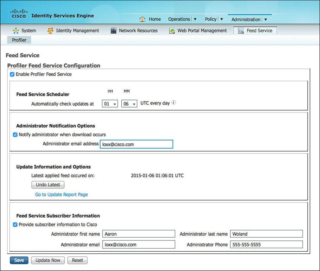
Figure 15-20 Configured profiling feed service.
When you don’t want to wait for a configured interval for the feed service to run, you can click an Update Now button. Be cautious with manually updating the profiles during a production workday. When the profiles are updated, it will cause all the endpoints in the endpoint database to be compared against the new list of profiles. In other words, a complete re-profiling of endpoints will occur, which can be very processor intensive.
Verifying the Profiler Feed Service
The easiest way to verify whether the feed service is operational is to click the Go to Update Report Page link on the configuration screen, located at Administration > Feed Service > Profiler, as shown in Figure 15-21.
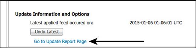
Figure 15-21 Go to update report page link.
Clicking that link opens another window with the Change Configuration Audit report prefiltered for the feed service related entries, as shown in Figure 15-22.
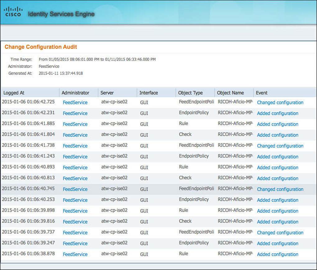
Figure 15-22 Change configuration audit for feed service.
Because ISE must be able to reach cisco.com for the profiling feed service to function, you might need to configure ISE to use a proxy server to reach the Internet. This optional configuration is located at Administration > System > Settings > Proxy, as shown in Figure 15-23.
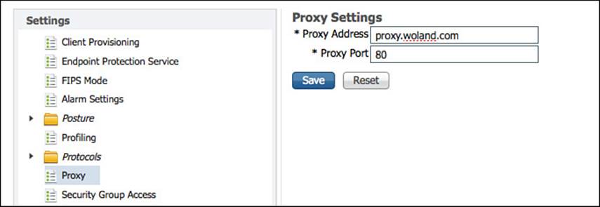
Figure 15-23 Proxy setting.
Endpoint Profile Policies
The profiling service probes collect attributes of endpoints, while the profile policies are similar to signatures, which define the endpoint profiles themselves. For example, to match an Apple-Device profile, the endpoint must have a MAC address beginning with Apple’s OUI.
Each endpoint profile policy defines a set of attributes that must be matched for a device to be classified as that endpoint type. ISE has a large number of predefined profile policies, and you have just read about the feed service that’s used to update those policies and provide new ones.
The endpoint profile policies can be viewed by navigating to Policy > Profiling, as shown in Figure 15-24.
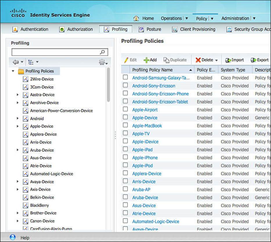
Figure 15-24 Policy > Profiling.
Each profile is listed as Cisco provided or Administrator Modified. This classification ensures that the feed service will not override one that has been changed by the administrator.
Profiles are hierarchical and inclusive in nature, and you can pick any level to use within your authorization policies, enabling you to be very specific or broad in your rules. Examining Figure 15-25, you see the existence of a parent policy named Cisco-Device with a child policy named Cisco-IP-Phone, and that has another child policy named Cisco-IP-Phone-7940 (Cisco-Device > Cisco-IP-Phone > Cisco-IP-Phone-7940).
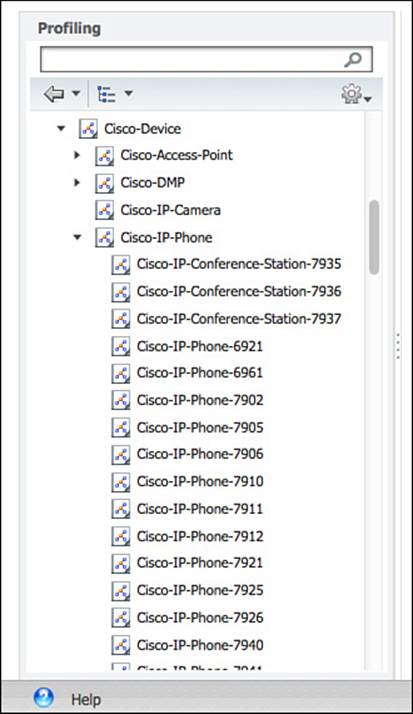
Figure 15-25 Cisco-Device parent profile.
When building an authorization policy, you can choose to use the profile at any point in that chain. If you were to select Cisco-Device, it would apply to all devices classified as Cisco-Device as well as anything classified as a child profile of Cisco-Device.
Figure 15-26 graphically displays the way a profile hierarchy is built within ISE.
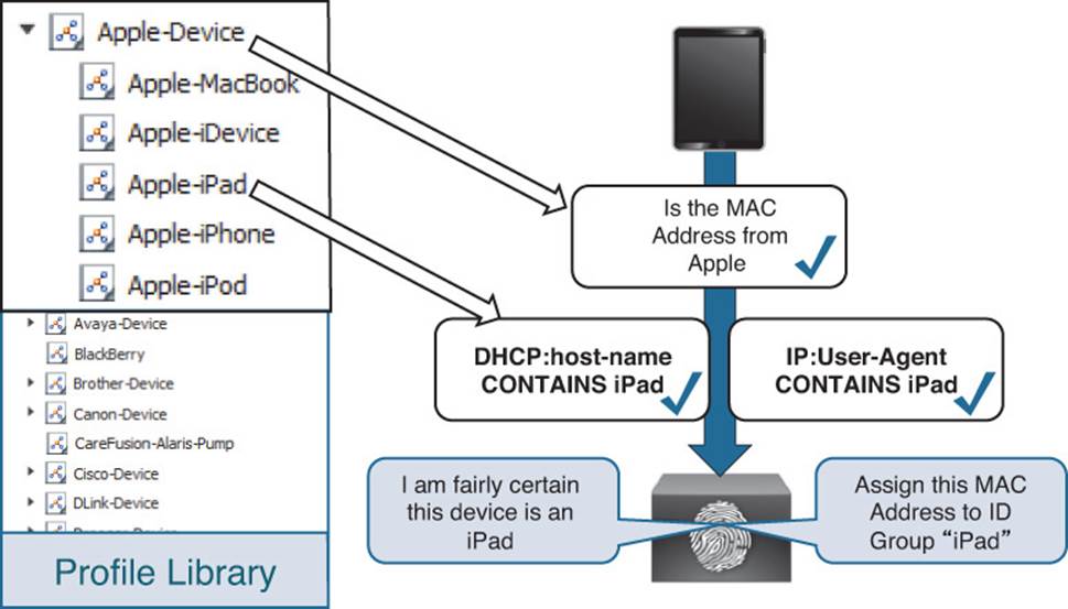
Figure 15-26 Profiling hierarchy illustrated.
To serve as further examples, there is a predefined authorization rule named Profiled Cisco IP Phones. This rule permits full access to the network and assigns permission to join the Voice VLAN for all devices that that are profiled as a Cisco-IP-Phone parent profile and any of the child profiles. Figure 15-27 shows this rule.
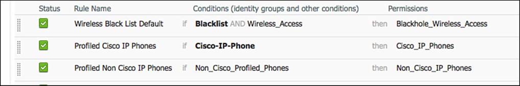
Figure 15-27 Default Profiled Cisco IP Phones rule.
Continuing to examine policy hierarchy and how it works, let’s dig into a specific example. In this sample network, there is a Cisco 7970 IP Phone, and that phone has been granted access from the Profiled Cisco IP Phones default authorization rule. This permits all devices matching a Cisco-IP-Phone profile Identity Group.
Start by examining the endpoint attributes and comparing them to the profiling policies.
Step 1. Navigate to Administration > Identity Management > Identities > Endpoints. Locate the 7970 phone, as shown in Figure 15-28.
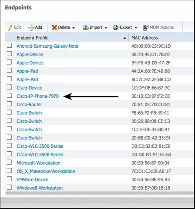
Figure 15-28 Filtered endpoint identities.
Step 2. Click that endpoint to enter into the endpoint details.
Step 3. You will immediately see that the Policy Assignment (profile of the device) is Cisco-IP-Phone-7970. However, the Identity Group Assignment is Cisco-IP-Phone. Additionally, the AuthorizationPolicyMatchedRule is Profiled Cisco IP Phones, which means the correct authorization rule is being matched, as shown in Figure 15-29.
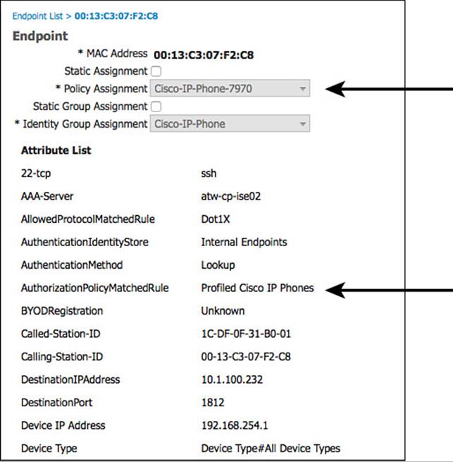
Figure 15-29 Endpoint details.
Step 4. Scroll downward in the endpoint details and see that the EndPointSource is the RADIUS probe, as shown in Figure 15-30. That means the RADIUS probe provided us with the most information needed to classify this device (which must have arrived from the device sensor on the NAD).
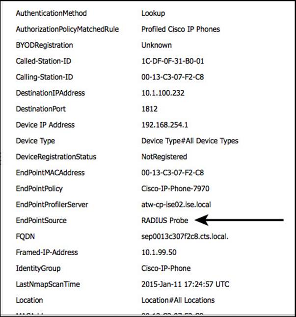
Figure 15-30 Endpoint details: EndPointSource.
Step 5. Continuing down the list of attributes, notice the CDP cached data from the switch that was sent to ISE via the RADIUS probe (see Figure 15-31).
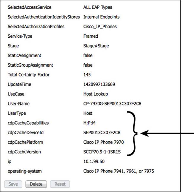
Figure 15-31 Endpoint details: CDP data.
You can see these attributes of the endpoint, but how is that used within the profiling policy? To answer that question, examine the profiling policy hierarchy for the endpoint.
Step 6. Navigate to Policy > Profiling > Cisco-Device. Cisco-Device is the top level of the profiling hierarchy for this endpoint, as shown in Figure 15-32.
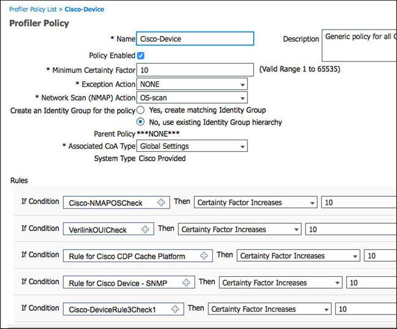
Figure 15-32 Cisco-Device profiling policy.
Using Figure 15-32 as a reference point, please take note of the following details:
![]() The minimum certainty factor of this profile is 10. Certainty factor is an aggregate value between 1 and 65535. Each of the conditions at the bottom of the policy that are matched will add up to equal the endpoints certainty value. The higher the value, the more certain ISE profiler is that an endpoint matches the specific profile.
The minimum certainty factor of this profile is 10. Certainty factor is an aggregate value between 1 and 65535. Each of the conditions at the bottom of the policy that are matched will add up to equal the endpoints certainty value. The higher the value, the more certain ISE profiler is that an endpoint matches the specific profile.
![]() Note that the OUI is CISCO SYSTEMS, INC., shown in Figure 15-33, and that will match the condition for Cisco-Device shown in Figure 15-34. This is one possible mapping that meets the minimum certainty value and should match the endpoint to this parent policy.
Note that the OUI is CISCO SYSTEMS, INC., shown in Figure 15-33, and that will match the condition for Cisco-Device shown in Figure 15-34. This is one possible mapping that meets the minimum certainty value and should match the endpoint to this parent policy.
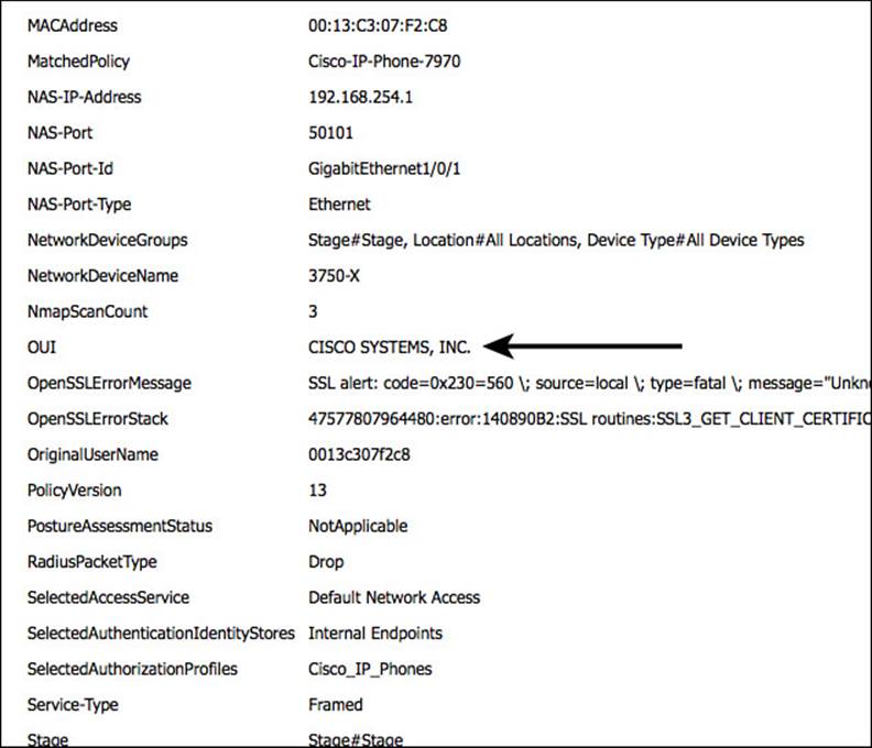
Figure 15-33 OUI of the endpoint.
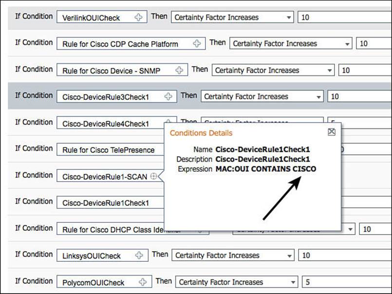
Figure 15-34 OUI condition in Cisco-Device policy.
![]() A Network Scan (NMAP) Action is set to OS-Scan. For this action to occur, there must be a condition in the profile that has a result to trigger the network scan. Figure 15-35 displays this mapping of the condition to the action. Figure 15-34 displays the contents of the condition, meaning that if the MAC OUI contains CISCO, then run the NMAP Scan type defined.
A Network Scan (NMAP) Action is set to OS-Scan. For this action to occur, there must be a condition in the profile that has a result to trigger the network scan. Figure 15-35 displays this mapping of the condition to the action. Figure 15-34 displays the contents of the condition, meaning that if the MAC OUI contains CISCO, then run the NMAP Scan type defined.
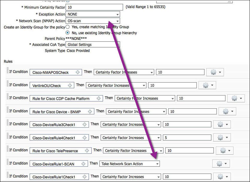
Figure 15-35 Network scan action and condition with scan result.
![]() This profiling policy has a tremendous number of conditions. Most of them add a certainty value of 5 or 10. The Certainty Value needs to be only a minimum of 10 to match the profile, so matching any one of these conditions will most likely equal a match.
This profiling policy has a tremendous number of conditions. Most of them add a certainty value of 5 or 10. The Certainty Value needs to be only a minimum of 10 to match the profile, so matching any one of these conditions will most likely equal a match.
Step 7. Navigate to Policy > Profiling > Cisco-Device > Cisco-IP-Phone, as shown in Figure 15-36, to examine the conditions used for this policy.
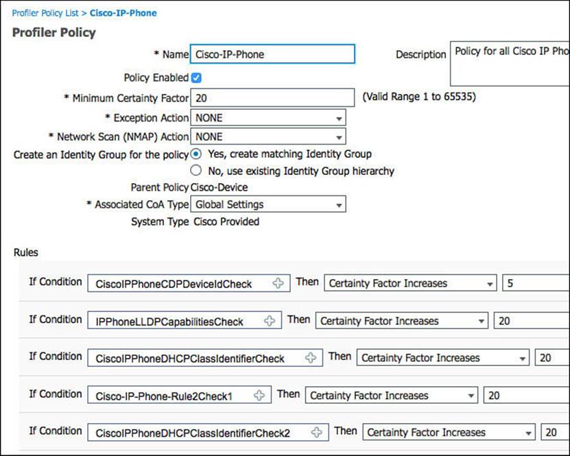
Figure 15-36 Cisco-IP-Phone profiling policy.
Using this profile as a reference point, please take note of the following details:
![]() To even be compared to this profiling policy, the device must have first matched its parent policy. In this case, the device had to match the Cisco-Device policy before these conditions would ever be examined.
To even be compared to this profiling policy, the device must have first matched its parent policy. In this case, the device had to match the Cisco-Device policy before these conditions would ever be examined.
![]() The minimum certainty factor of this profile is 20, as shown in Figure 15-36. Certainty factor is an aggregate value between 1 and 65535. Each of the conditions at the bottom of the policy can add more certainty to this profile, if they are matched.
The minimum certainty factor of this profile is 20, as shown in Figure 15-36. Certainty factor is an aggregate value between 1 and 65535. Each of the conditions at the bottom of the policy can add more certainty to this profile, if they are matched.
![]() The CDP Cache shown in Figure 15-31 shows that the cdpCachePlatform attribute was sent as Cisco IP Phone 7970.
The CDP Cache shown in Figure 15-31 shows that the cdpCachePlatform attribute was sent as Cisco IP Phone 7970.
![]() Figure 15-37 shows that the Cisco IP Phone profile policy uses a condition looking for the cdpCachePlatform value to contain Cisco IP Phone and increase the certainty by 20.
Figure 15-37 shows that the Cisco IP Phone profile policy uses a condition looking for the cdpCachePlatform value to contain Cisco IP Phone and increase the certainty by 20.
Step 7 examined Cisco-IP-Phone, but what does it take to get one step further, to reach the final Cisco-IP-Phone-7970 profile?
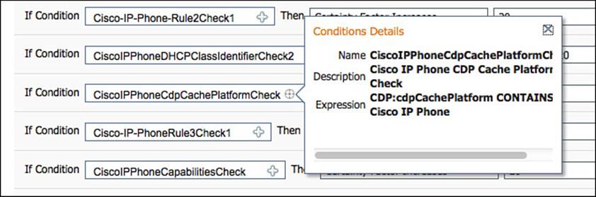
Figure 15-37 cdpCachePlatform condition.
Step 8. Navigate to Policy > Profiling > Cisco-Device > Cisco-IP-Phone > Cisco-IP-Phone-7970, and we will examine the conditions used for this policy (see Figure 15-38).
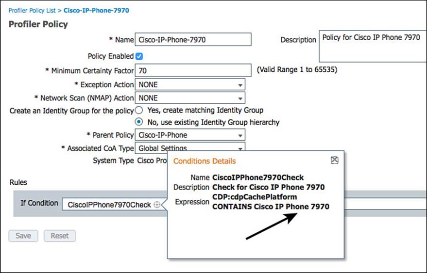
Figure 15-38 Cisco-IP-Phone-7970 profile.
Using Figure 15-38 as a reference point, please take note of the following details:
![]() To even be compared to this profiling policy, the device must have first matched its parent policy. In this case, the device had to match the Cisco-Device and Cisco-IP-Phone policy before these conditions would ever be looked at.
To even be compared to this profiling policy, the device must have first matched its parent policy. In this case, the device had to match the Cisco-Device and Cisco-IP-Phone policy before these conditions would ever be looked at.
![]() The profile itself has only one condition, and that condition is that the cdpCachePlatform attribute is Cisco IP Phone 7970. Figure 15-31 has shown that it is.
The profile itself has only one condition, and that condition is that the cdpCachePlatform attribute is Cisco IP Phone 7970. Figure 15-31 has shown that it is.
Rarely would you build an authorization policy that is specific to the point of the model number of the Cisco Phone; instead you would just use the Cisco-IP-Phone parent policy in your authorization policies.
Logical Profiles
When ISE 1.0 was first released, it was quickly requested by many customers to have a grouping of profiles that are not hierarchical. For example, many requested to create a profile group named IP-Phones that contains all the individual profiles of IP phones, Cisco and non-Cisco alike.
ISE 1.2 answered that request. With that release, Cisco introduced the new concept of logical profiles. These logical profiles are exactly what customers requested: a grouping of profiles.
To examine the only prebuilt logical profile in ISE, navigate to Policy > Profiling > Logical Profiles. Select IP-Phones, as shown in Figure 15-39.
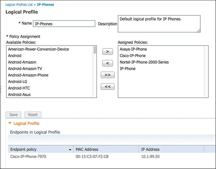
Figure 15-39 IP-Phones logical profile.
Notice in Figure 15-39 that the logical profile contains Avaya, Cisco, Nortel, and generic IP phone profiles.
ISE Profiler and CoA
When using an endpoint profile as an attribute within your authorization policy, you will be providing differentiated results for specific profiles. However, there is often a “chicken and the egg” phenomenon happening simultaneously. You cannot provide the right access to a device without knowing what that devices is, yet you cannot find out what the device is without providing some level of access. The endpoint must be active on the network for ISE to identify the endpoint profile.
Enter the concept of change of authorization (CoA), which was introduced to you in Chapter 6. Without CoA, the only time a policy server such as ISE is permitted to send a command to the NAD is during a response to an authentication request. This created numerous issues because there would not be a way to disconnect a bad actor from the network or change the level of access an endpoint is permitted to have based on a newer data that has been learned at the policy engine. The current authorization to the network would have to sustain until the next time the endpoint has to authenticate.
Because the authorization policy can be configured to send different results for an endpoint before it is profiled and then send another level of authorization after the endpoint profile becomes nailed down further and the final result after the endpoint profile is definitely known, you cannot wait for the next authentication request each time. Instead, the profiling engine can use CoA to change the level for each state the endpoint goes through.
There are two main areas for configuring CoA with profiling. A global setting enables CoA for profiling in the ISE deployment, and a CoA can be configured on a per-profile basis.
Global CoA
To enable CoA for profiling in the ISE cube, and to configure the CoA type used by profiling globally, navigate to Administration > System > Settings > Profiler, as shown in Figure 15-40.
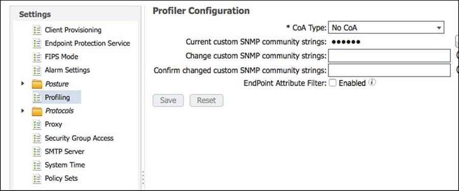
Figure 15-40 Profiler global settings.
As shown in Figure 15-40, the default setting is No CoA. Click the drop-down list, as shown in Figure 15-41, to see the choices: Port Bounce and Reauth.
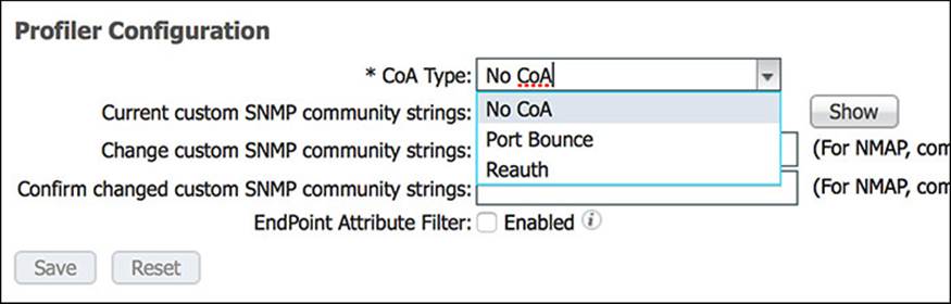
Figure 15-41 Profiler CoA types.
The Port Bounce CoA shuts down the switch port and then performs a no shutdown to reenable it. This causes the link state to change, simulating the unplugging and plugging in of network cable. The benefit to this type of CoA is that many devices will try to renew their DHCP assigned IP addresses when the link state changes. Additionally, there is a built-in failsafe to never send a Port Bounce when more than one MAC address is seen on the switch port. That failsafe is in place to ensure there is no negative impact on IP telephony. When more than one MAC address exists on the switch port, a Reauth is sent instead.
The Reauth CoA instructs the NAD to initiate a new authentication to the endpoint, sending another EAPoL Start message to trigger the supplicant to send the credentials again. In the case of MAB, however, the NAD resends a RADIUS authentication with the endpoint MAC address as the identity credential. Either way there is a new authentication, but that authentication maintains the same authentication session ID. By maintaining the session ID, ISE is able to tie together the multiple states of the endpoint.
Regardless of the CoA type used, ISE has now forced a new authentication attempt so that a different authorization result can be sent to the NAD, providing the correct level of network access with the latest profiling information being used. However, setting a global CoA type to Port Bounce is not recommended. The safer bet is to use the Reauth option.
After the profiler CoA is enabled globally, a CoA is automatically sent for any endpoint that transitions from unknown to any known profile.
Per-profile CoA
ISE 1.2 added a new setting to profiles that enable an administrator to control her own destiny with CoA. This came about with the need to send a Port Bounce CoA for certain devices only, while using the global Reauth CoA for the remaining endpoints.
This is known as the per-profile CoA. When a CoA type is configured for a profile, it is used when an endpoint is classified as that profile type. The setting is shown in Figure 15-42.
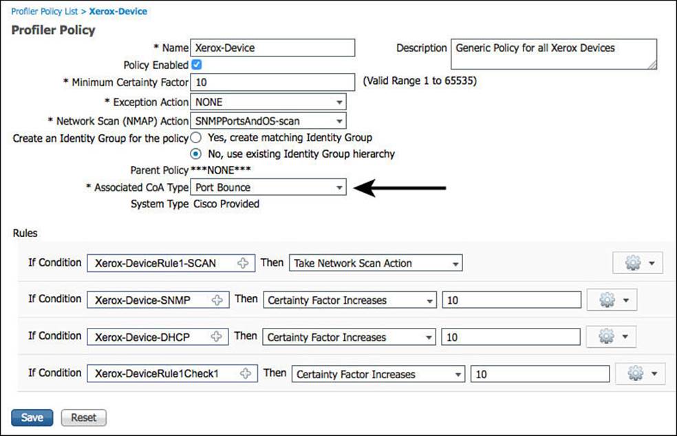
Figure 15-42 Per-profile CoA.
As shown in Figure 15-42, a device profiled as a Xerox-Device will now trigger a Port Bounce CoA, causing the link to go down and back up again. This in turn triggers the endpoint to request a new IP address from the DHCP server. This is useful when a device is using MAB and needs to be assigned to a different VLAN.
Global Profiler Settings
Additional settings related to profiling are set at the global (system-wide) level, not just the global CoA type. These include the SNMP community strings for NMAP SNMP walks and the enable setting for endpoint attribute filtering.
Configuring SNMP Settings for Probes
The SNMPQUERY probe uses the SNMP community strings that are defined as part of the NAD entry under Administration > Network Resources > Network Devices. Each NAD could theoretically have a different community string.
As described in the Network Scan (NMAP) section, NMAP uses SNMP to examine endpoints. For this to function, ISE profiler must know which SNMP community strings to use. The community strings to use are configured within Administration > System > Settings > Profilerand are configured by listing each community string one-by-one with a comma separating each value. After they are saved, the two text boxes are erased; you then must click the Show button to see the configured strings, as displayed in Figure 15-43.
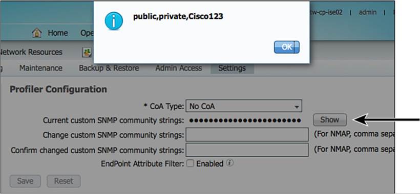
Figure 15-43 Global SNMP settings for NMAP probe.
Endpoint Attribute Filtering
ISE Profiler can and does collect a lot of data about endpoints. It stores all that data and replicates it to the other ISE nodes in the deployment. To help keep the replication traffic down, ISE has endpoint attribute filters, which are enabled at Administration > System > Settings > Profiling, as shown in Figure 15-44.
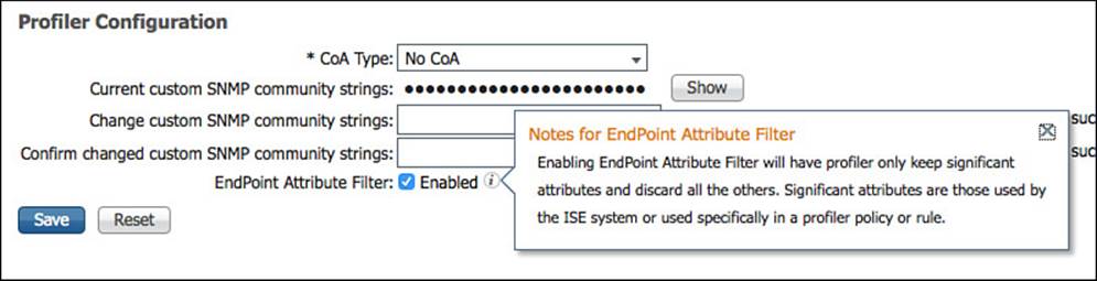
Figure 15-44 Endpoint attribute filter.
When the filtering is enabled, profiler builds a white list of attributes that are used in the existing profiler policies. In other words, the profiler examines every policy that is enabled and creates a list of attributes that are needed for all those policies. Only those attributes will now be collected and stored in the endpoint database.
Use of the endpoint attribute filter is highly recommended but only after a deployment has been up and running properly for an extended period of time. The reason it is not recommended for use immediately with an ISE install is to enable the administrator to have all the necessary attributes to build new profiles. If the list of collected attributes is filtered down, there might not be enough data available to create the necessary profiles.
Profiles in Authorization Policies
As you saw with the profiled Cisco IP phone authorization rule earlier in this chapter, the profile can be used as a condition of an authorization policy rule in the form of an identity group. Originally, ISE required an identity group to use any of the profiling policies in the rule; however, it has evolved into the ability to use the profile directly (called the EndPointPolicy).
Endpoint Identity Groups
Local identities within the ISE database can be in the form of user identities or endpoint identities. Some identity groups can contain multiple identities, although an identity (user or endpoint) can be a member of only one identity group at a time.
To create an identity group based on the profile, you simply select the labeled Yes, Create Matching Identity Group option on the profile, as displayed in Figure 15-45.
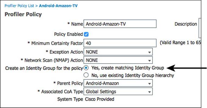
Figure 15-45 Create matching identity group.
If that option is selected, the matching identity group will be found under Administration > Identity Management > Groups > Endpoint Identity Groups (as shown in Figure 15-45).
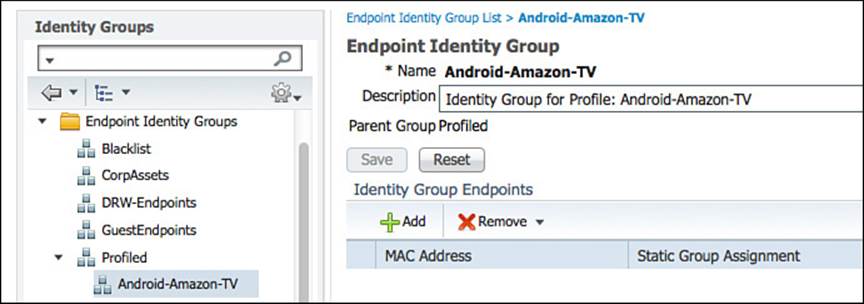
Figure 15-46 Endpoint identity groups.
Even though endpoint identity groups were the way to go with ISE 1.0, the use of them for profiling has been deprecated in favor of using the actual endpoint profile or logical profiles directly in the authorization policy.
Therefore, starting with ISE 1.2, endpoint identity groups are used for a different purpose. They are used for more of a MAC Address Management (MAM) model, where you can create a static list of MAC addresses to be authorized specifically. For example, you could create a list of all Apple iPads that are owned by the company so they can be differentiated from personally owned iPads.
The Blacklist identity group is a perfect example of identity group usage in this manner. If a user were to lose his personal device, he would be able to log in to the MyDevices portal and mark a device as lost, as shown in Figure 15-47. This would immediately add the endpoint to the Blacklist group, as shown in Figure 15-48. The device would then be denied network access by default, as shown in Figure 15-49.
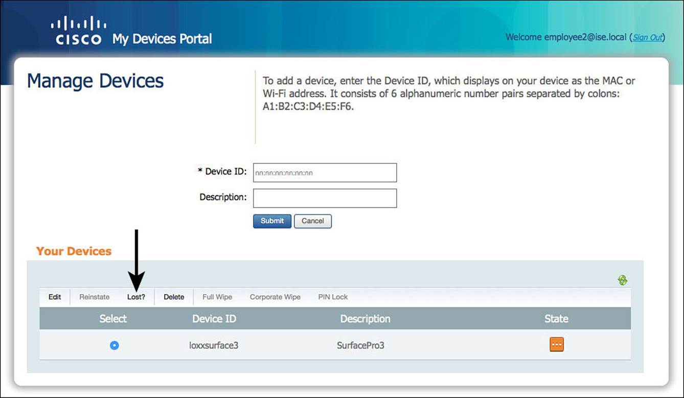
Figure 15-47 MyDevices: Mark endpoint as lost.
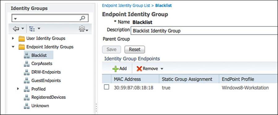
Figure 15-48 Blacklisted devices.
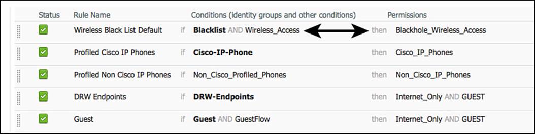
Figure 15-49 Default blacklist authorization rule.
From the MyDevices portal, selecting Reinstate moves the device from the Blacklist group to the RegisteredDevices group. Figure 15-50 shows the MyDevices portal, and Figure 15-51 shows the RegisteredDevices group.
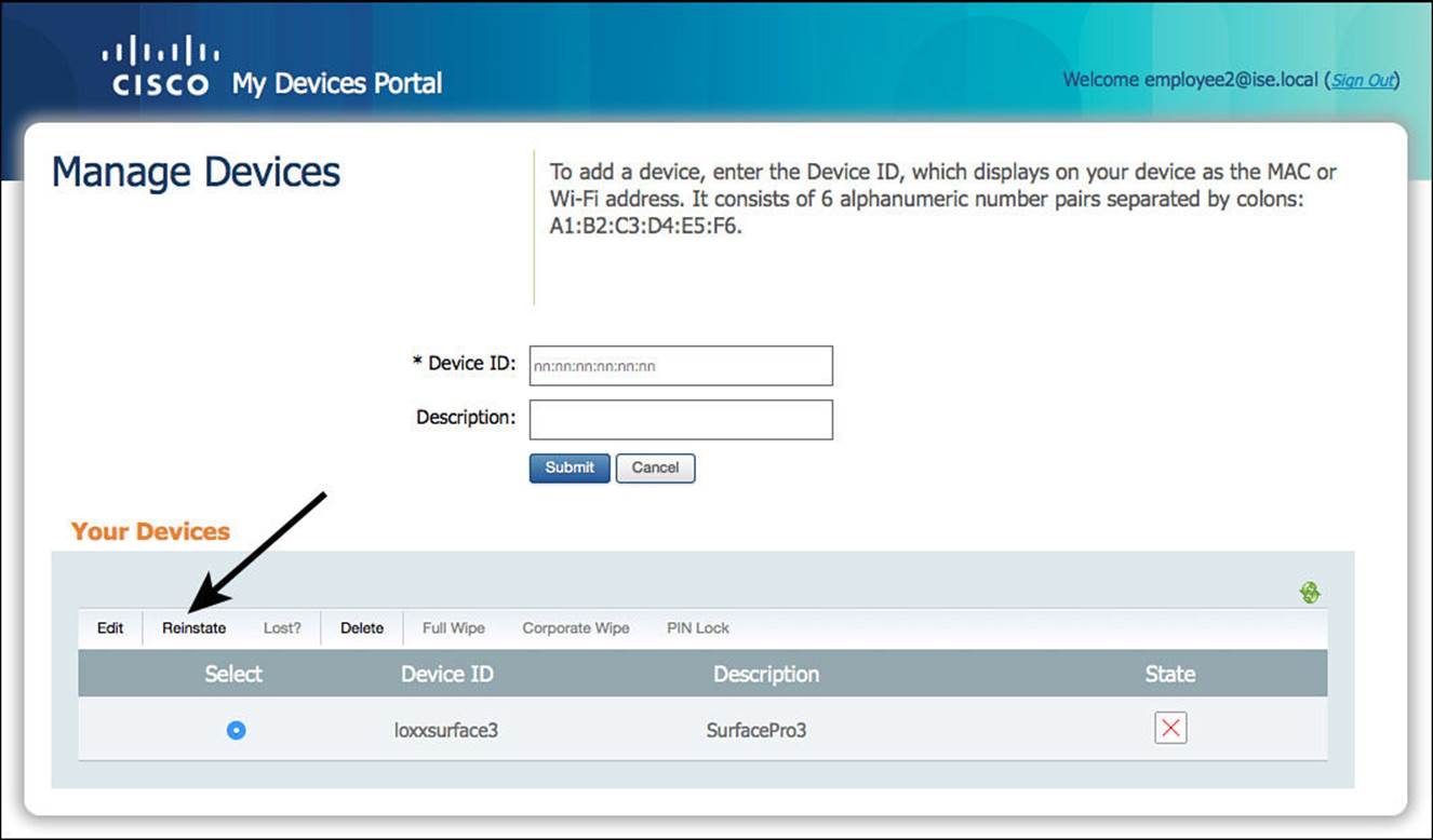
Figure 15-50 MyDevices: Reinstate the endpoint.
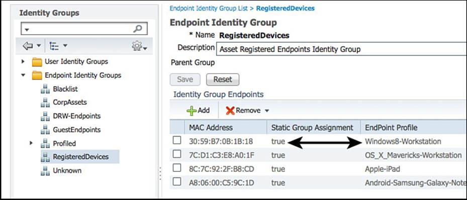
Figure 15-51 RegisteredDevices endpoint identity group.
EndPointPolicy
Beginning with ISE 1.2, identity groups are no longer the way to apply policy based on the endpoint’s profile. Policy is now built with the actual profile through the use of the Endpoints:EndPointPolicy attribute.
To see the use of the profile in a policy, you will duplicate the existing NSP authorization rule and then modify that new rule to use the Android profile, which does not have a corresponding identity group.
From the ISE GUI, do the following:
Step 1. Navigate to Policy > Authorization.
Step 2. Duplicate the NSP rule.
Step 3. Add a new condition matching Android devices to the existing MSCHAP condition of Endpoints > EndPointPolicy.
Figure 15-52 shows the resulting authorization rule.
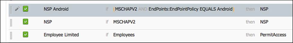
Figure 15-52 Authorization rule using the EndPointPolicy condition.
Throughout all of this, always keep in mind the simplicity of using logical profiles to streamline your authorization policies, and limit the number of individual EndPointPolicies that you need to add to your authorization rules.
Verify Profiling
There are a few key places to verify profiling operation. Most exist within the ISE GUI, and of course you should always examine the network device itself.
The Dashboard
The dashboard is always the first screen you see when you log in to the ISE GUI, as shown in Figure 15-53. Right on the dashboard are numerous places to look to see whether profiling is working.
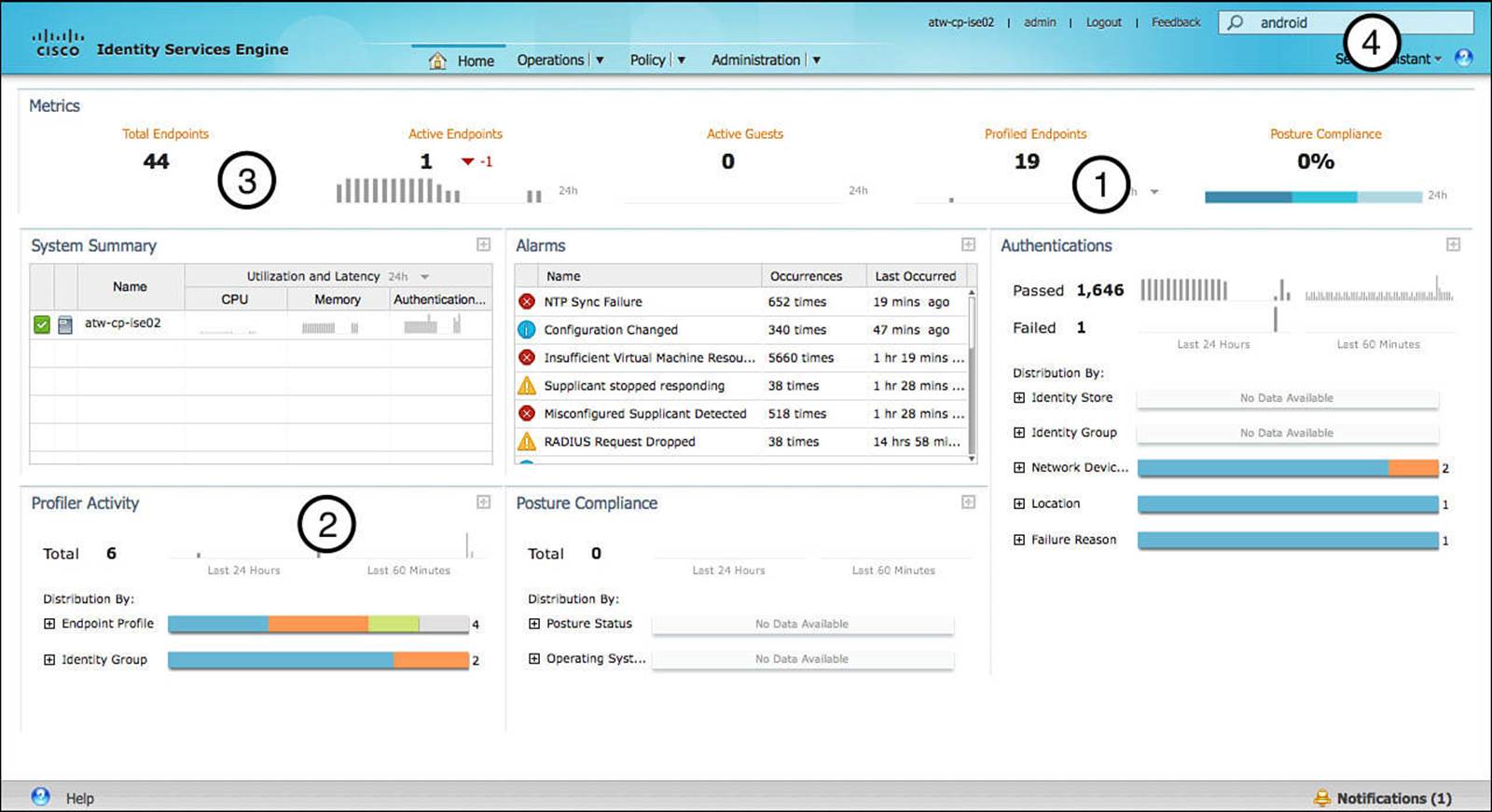
Figure 15-53 The Cisco ISE dashboard.
Examining Figure 15-53, four areas of the dashboard are called out:
![]() Profiled Endpoints Counter (1)—This counter shows the number of endpoints that have been profiled in the last 24 hours.
Profiled Endpoints Counter (1)—This counter shows the number of endpoints that have been profiled in the last 24 hours.
![]() Profiler Activity Window (2)—This shows a bit more detail than the Profiled Endpoints Counter; it shows two different counters: last 60 minutes and 24 hours. It also lists the individual profiles in a color-coded graph and can be expanded. The entire window can be expanded to see more detail.
Profiler Activity Window (2)—This shows a bit more detail than the Profiled Endpoints Counter; it shows two different counters: last 60 minutes and 24 hours. It also lists the individual profiles in a color-coded graph and can be expanded. The entire window can be expanded to see more detail.
![]() The Total Endpoints Counter (3)—This shows the total number of endpoints that have been examined by the MnT persona within the ISE cube. What makes this particular counter so interesting is what happens after you click it. This is examined in detail in the next section, “Endpoints Drill-down.”
The Total Endpoints Counter (3)—This shows the total number of endpoints that have been examined by the MnT persona within the ISE cube. What makes this particular counter so interesting is what happens after you click it. This is examined in detail in the next section, “Endpoints Drill-down.”
![]() Global Search (4)—This search bar enables you to search based on the profile, MAC address, or even username. This tool is covered in more detail in the section “Global Search.”
Global Search (4)—This search bar enables you to search based on the profile, MAC address, or even username. This tool is covered in more detail in the section “Global Search.”
Endpoints Drill-down
Often thought of as the best kept secret in ISE, the Endpoints Drill-down tool is frequently overlooked or unknown. Just like the rest of the dashboard, it is part of the MnT persona (not the PSN persona) and therefore displays a result based on the logs sent from the PSN to the MnT node and not the actual endpoint database. Although these can often contain the same data, they can sometimes not match identically, due to log purging.
Regardless of where the data is sourced from, the tool is an excellent way to look into the profiled endpoints and verify that the profiling service is working. Figure 15-54 shows the Endpoints Drill-down tool that appears when you click the total endpoints counter (#3 in Figure 15-53).
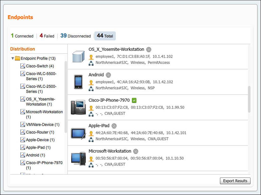
Figure 15-54 Endpoints Drill-down.
Selecting items from the left side of the tool filters the list of endpoints, and each endpoint can be drilled into further on the right side of the tool. In addition, the endpoint list can be exported with the Export button in the lower-right corner.
Global Search
The Global Search tool is available from any screen within the ISE GUI. Typing in a profile name displays results that can be drilled into further. Figure 15-55 shows the use of the Global Search tool to find profiles containing “Apple.”
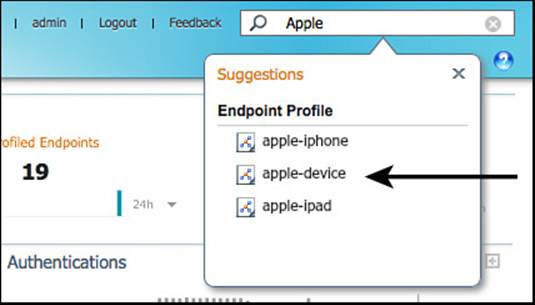
Figure 15-55 Global searching for Apple.
Selecting Apple-Device from the resulting list displays a more focused list of endpoints matching that profile, as shown in Figure 15-56.
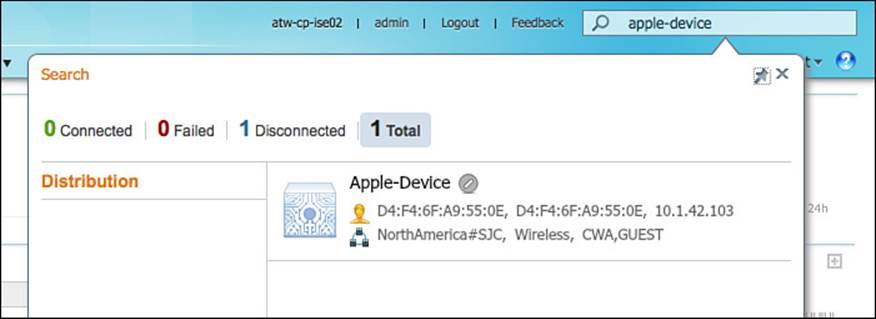
Figure 15-56 Apple-Device.
Endpoint Identities
The ultimate source of truth about endpoints is the actual endpoints database. The graphical view of that list of endpoints is located at Administration > Identity Management > Identities > Endpoints. This brings up the endpoints table, and the profile of the endpoint is visible in the first column.
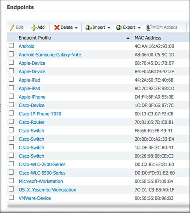
Figure 15-57 Endpoints table.
Clicking any of the endpoints in the table will bring up the endpoint details. The list of details maintained for each endpoint can be quite large, especially if the Endpoint Attribute Filter is not enabled. Figure 15-58 shows the endpoint details screen for an Apple iPhone, and Figure 15-59 shows some of the details further down the list, including the HTTP probe being given credit for the final profile assignment.
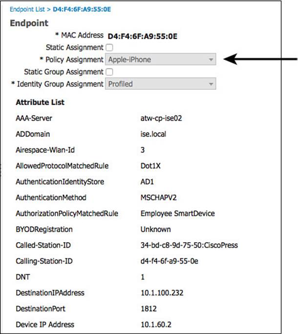
Figure 15-58 Endpoints details.
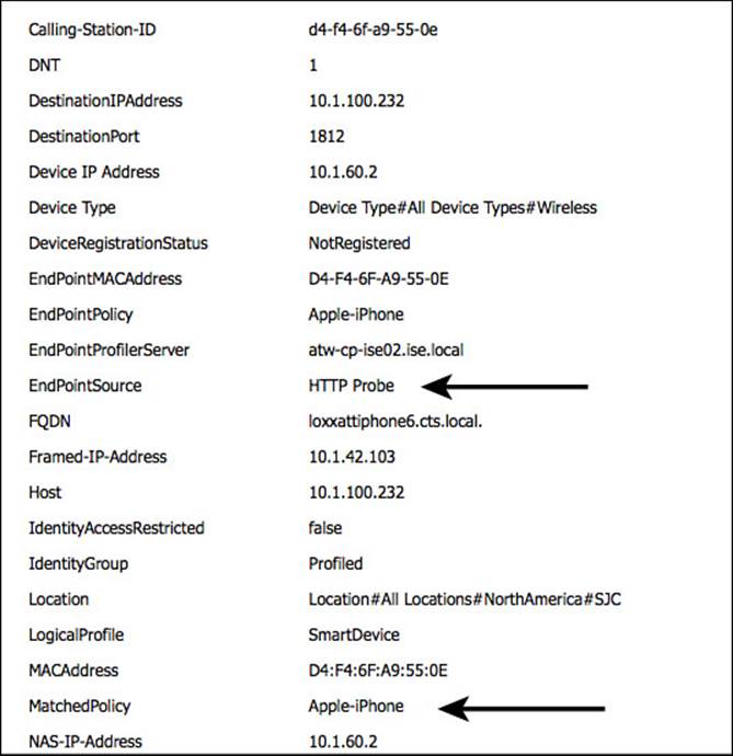
Figure 15-59 Endpoint details, continued.
Device Sensor Show Commands
With Cisco switches that run device sensor, there is a show command specifically for the device sensor capability in the switch: show device sensor cache [ all | mac ]. Example 15-13 displays the output of the show command. While the values might not make a lot of sense to a human being, it does demonstrate that the device sensor is collecting and caching profiling data.
Example 15-13 show device-sensor cache all
3750-X#show device-sensor cache all
Device: 0050.5687.0004 on port GigabitEthernet1/0/2
--------------------------------------------------
Proto Type:Name Len Value
dhcp 43:vendor-encapsulated-optio 5 2B 03 DC 01 00
dhcp 55:parameter-request-list 14 37 0C 01 0F 03 06 2C 2E 2F 1F 21 F9 2B FC
dhcp 60:class-identifier 10 3C 08 4D 53 46 54 20 35 2E 30
dhcp 12:host-name 12 0C 0A 58 59 5A 2D 42 69 6F 4D 65 64
dhcp 61:client-identifier 9 3D 07 01 00 50 56 87 00 04
dhcp 77:user-class-id 13 4D 0B 73 79 6D 75 6E 75 73 2D 62 69 6F
Exam Preparation Tasks
Review All Key Topics
Review the most important topics in the chapter, noted with the key topics icon in the outer margin of the page. Table 15-2 lists a reference of these key topics and the page numbers on which each is found.
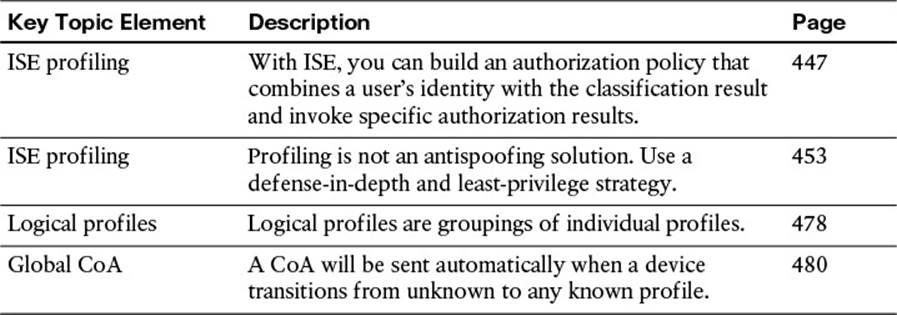
Table 15-2 Key Topics for Chapter 15
All materials on the site are licensed Creative Commons Attribution-Sharealike 3.0 Unported CC BY-SA 3.0 & GNU Free Documentation License (GFDL)
If you are the copyright holder of any material contained on our site and intend to remove it, please contact our site administrator for approval.
© 2016-2026 All site design rights belong to S.Y.A.