CCNP Security SISAS 300-208 Official Cert Guide (2015)
Part VI: Safely Deploying in the Enterprise
Chapter 21. ISE Scale and High Availability
This chapter covers the following exam topics:
![]() Configuring ISE nodes in a distributed environment
Configuring ISE nodes in a distributed environment
![]() Understanding the HA options available
Understanding the HA options available
![]() Using load balancers
Using load balancers
![]() Maintaining ISE deployments
Maintaining ISE deployments
Note
These topics are not specific exam objectives, but they are on the exam.
Although ISE can run with all services on a single physical or virtual appliance, there is still the issue of scale. A single appliance cannot scale to large enterprise levels, nor would that model be highly resilient to failure.
ISE cubes can be designed with each persona running on separate physical or virtual appliances in a single location or multiple locations. Additionally, there are features within ISE and the network access devices (NADs) themselves that provide redundancy for authentication.
Availability of a solution should be a full strategy, not just a product feature. Planning for patching and backups of the solution are critical items to ensure availability.
“Do I Know This Already?” Quiz
The “Do I Know This Already?” quiz enables you to assess whether you should read this entire chapter thoroughly or jump to the “Exam Preparation Tasks” section. If you are in doubt about your answers to these questions or your own assessment of your knowledge of the topics, read the entire chapter. Table 21-1 lists the major headings in this chapter and their corresponding “Do I Know This Already?” quiz questions. You can find the answers in Appendix A, “Answers to the ‘Do I Know This Already?’ Quizzes.”
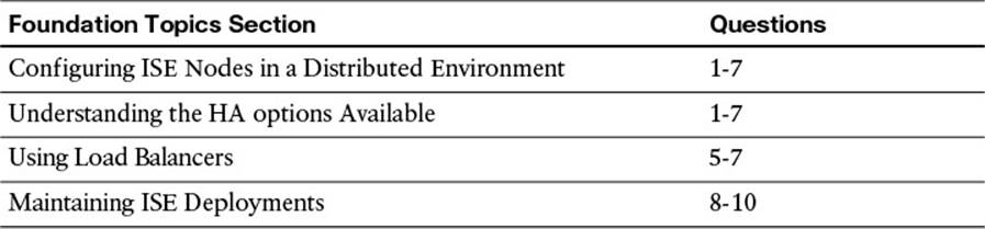
Table 21-1 “Do I Know This Already?” Section-to-Question Mapping
Caution
The goal of self-assessment is to gauge your mastery of the topics in this chapter. If you do not know the answer to a question or are only partially sure of the answer, you should mark that question as wrong for purposes of the self-assessment. Giving yourself credit for an answer you correctly guess skews your self-assessment results and might provide you with a false sense of security.
1. How does a PSN join an ISE cube?
a. From the Deployment screen on the secondary nodes, select Join Cube and enter the FQDN and credentials of the cube controller.
b. From the Deployment screen on the PAN, click Create Cube. Then click Register and add the FQDN and credentials for the other nodes.
c. From the Deployment screen on the PAN, click Register and add the FQDN and credentials for the other nodes.
d. PSNs are standalone. They do not join an ISE cube.
2. True or False? When joining a node to an ISE cube, you specify which personas the node should have.
a. True
b. False
3. Which three pieces of information are needed for an ISE license?
a. The output from the show license CLI command.
b. The unique device ID (UDID), version number (VPID), and serial number
c. The product ID (SPID), unique device ID (UDID), and serial number
d. The product ID (SPID), version number (VPID), and serial number
4. How does HA work for an ISE policy administration node?
a. Gigabit Ethernet 4 is used for stateful heartbeat. When the primary no longer responds, the secondary takes over.
b. The secondary is manually promoted from the secondary’s GUI.
c. The secondary is manually promoted from the primary’s GUI.
d. There is no HA for the policy administration node.
5. How does the monitoring persona’s high availability work?
a. ISE uses TCP syslog, and if the primary node does not respond, then the other nodes will send logs to the secondary.
b. Gigabit Ethernet 4 is used for stateful heartbeat. When the primary no longer responds, the secondary takes over.
c. Monitoring persona does not have an HA function.
d. Logs are sent to both MnT nodes automatically. If one MnT node goes down, the other node is still receiving logs.
6. What is the purpose of a node group?
a. Node groups are used for stateful sync between PSNs. If one PSN goes down, another PSN from the node group will assume its sessions automatically.
b. Node groups are used for a multicast heartbeat between PANs. If one PAN goes down, another PAN from the node group will take over.
c. Node groups are used for a multicast heartbeat between PSNs. If one PSN goes down, another PSN from the node group will send a change of authorization (CoA) for establishing sessions of the fallen node.
d. Node groups are used for a multicast heartbeat between MnT nodes. If one MnT goes down, another MnT from the node group will take over.
7. True or False? Cisco ISE cannot be used with load balancers.
a. True
b. False
8. How are patches applied to Cisco ISE?
a. Patches are downloaded and applied automatically using Cisco github.
b. Patches are downloaded from Cisco.com and applied through the GUI.
c. Patches are downloaded but not applied automatically. They are downloaded from Cisco github.
d. Patches are downloaded and applied automatically as part of the ISE feed service.
9. How do you verify the status of an ISE backup?
a. The status can be viewed only from the CLI.
b. The status of a restore is available in the GUI, but not backup status.
c. The status is not viewable in ISE version 1.2.
d. The status of a backup can be viewed from the GUI under Administration > System > Backup & Restore.
10. Where do you set the order for patching ISE nodes?
a. This is configured under Administration > System > Settings > Patch Management.
b. It is configured on the Administration > System > Maintenance > Patch Management page.
c. It is not configurable and will patch all nodes simultaneously.
d. It is not configurable and will patch all nodes in alphabetical order.
Foundation Topics
Configuring ISE Nodes in a Distributed Environment
As you should recall from Chapter 7, “Cisco Identity Services Engine Architecture,” ISE has multiple personas or functions. Table 21-2 contains a simple chart of personas and which function that persona provides. The third column in Table 21-2 provides the friendly name for an ISE node that is running that service or persona.
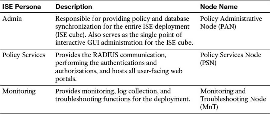
Table 21-2 ISE Persona Types
All ISE nodes are installed in a standalone mode by default. When in a standalone mode, the ISE node will be configured to run all personas by default. That means that the standalone node will run administration, monitoring, and policy services.
It is up to you, the ISE administrator, to promote the first node to be a primary and then join the additional nodes to this new deployment (known as an ISE cube). At the time of joining, you will also determine which services will run on which nodes; in other words, you will determine which persona the node will have.
Making the First Node a Primary Device
Because all ISE nodes are standalone by default, we must first promote the ISE node that will become the primary policy administration node to be a primary device, instead of a standalone.
From within the ISE GUI, do the following:
Step 1. Navigate to Administration > System > Deployment.
Step 2. Select the ISE node (there should only be one at this point), as shown in Figure 21-1.
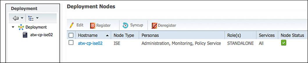
Figure 21-1 Deployment screen.
Step 3. Click the Make Primary button, as shown in Figure 21-2.
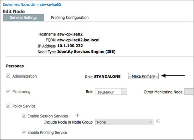
Figure 21-2 Make Primary button.
At this point, the Monitoring and Policy Service check boxes have become selectable. If the primary node will not also be providing any of these services, uncheck them now. (You can always come back and make changes later.)
Step 4. Click Save.
Registering an ISE Node to the Deployment
Now that there is a primary administrative node, you can finally have a multinode deployment. From the GUI on the primary admin node, you will register and assign personas to all ISE nodes.
Note
To join another ISE node to the deployment, both nodes must have mutual trust. In other words, all nodes must trust each other’s certificates. The easiest way to accomplish this is to use signed certificates on all nodes prior to joining them to a single cube. Refer toChapter 9, “Initial Configuration of Cisco ISE,” for a detailed walkthrough of replacing the self-signed certificates with a signed certificate.
To register a new node to the primary and form your ISE cube, follow these steps:
Step 1. Navigate to Administration > System > Deployment.
Step 2. Click Register > Register an ISE Node, as shown in Figure 21-3.
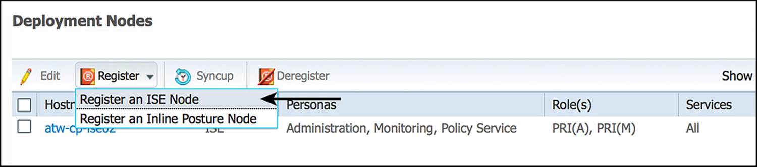
Figure 21-3 Register an ISE node.
Note
As with all other operations with ISE, DNS is a critical component.
Step 3. Enter the DNS name or IP address of the first ISE node you will be joining to the cube.
Step 4. Enter the administrator name (admin by default) and password. Figure 21-4 shows the registration page, with the hostname and credentials entered.
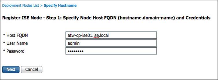
Figure 21-4 Specify the hostname and credentials.
Step 5. Click Next.
The next screen is the Configure Node screen, as shown in Figure 21-5. On this screen, you choose the main persona of the ISE node, including the enabling of profiling services. However, you cannot configure the individual profiling probes at this point.
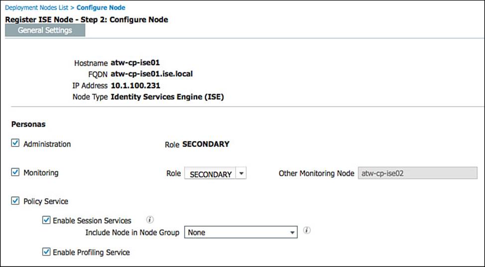
Figure 21-5 Configure node.
Step 6. Choose the personas to run on the newly registered node.
Notice in Figure 21-5 that the Administration and Monitoring personas are automatically configured to be secondary, leaving the existing node as the primary node in the ISE cube.
Step 7. Click Next.
At this point, the primary PAN will sync the entire configuration and the databases to the newly joined ISE node. A success message will be displayed communicating the impending synchronization, as shown in Figure 21-6.
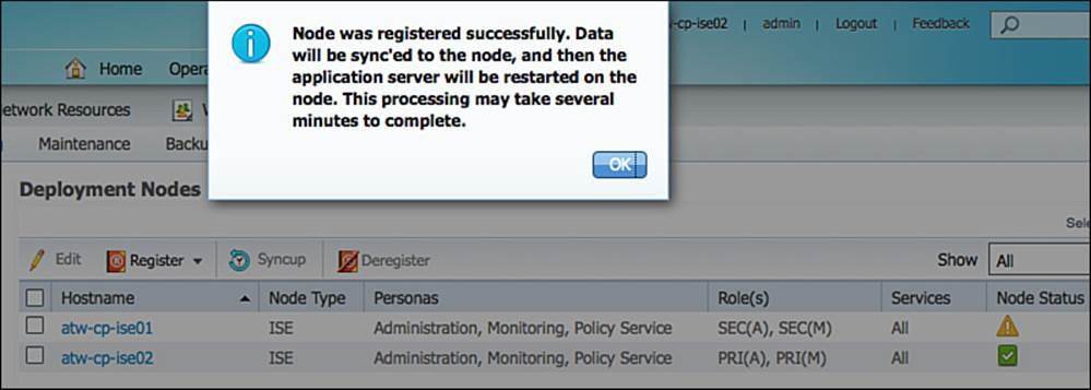
Figure 21-6 Sync initiated.
Step 8. Repeat steps 2-7 for all the ISE nodes that should be joined to the same cube.
Ensuring the Personas of All Nodes Are Accurate
Now that all your ISE nodes are joined to the deployment, you can ensure that the correct personas are assigned to the appropriate ISE nodes. Table 21-3 shows the ISE nodes in our sample deployment and the associated persona that will be assigned.
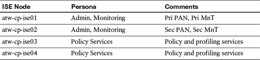
Table 21-3 ISE Nodes and Personas

This is also a good time to double-check that all the desired probes are enabled on the PSNs. Many customers have called Cisco TAC complaining of “database not replicating” problems, but it actually turned out to be that the probes were not enabled. Remember that even though you enable profiling services when joining a PSN to the ISE cube, none of the actual profiler probes are enabled by default. For detail on enabling profiler probes, see Chapter 15, “Profiling.”
Table 21-3 lists the ISE nodes used within this book’s examples and their personas; Figure 21-7 shows the Deployment screen with all nodes joined to the ISE cube.
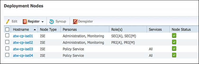
Figure 21-7 Final personas and roles.
Licensing in a Multinode ISE Cube
The good news is that ISE uses a centralized pool of licenses, where all nodes within an ISE cube share the single set of licenses (base and advanced). Therefore, there is no need to focus on how many licenses exist per PSN or anything of that nature.
However, you will need to ensure that licenses are issued with both the primary and secondary administrative nodes listed. When requesting licenses, you should supply three pieces of information about each administrative node: the product ID (SPID), version number (VPID), and serial number.
Example 21-1 shows logging in to an ISE node and using the show udi command to obtain this information from the primary administrative node (atw-cp-ise02). Example 21-2 repeats the same command on the secondary administrative node (atw-cp-ise01).
Example 21-1 show udi Command and Output from the Primary Administrative Node
atw-cp-ise02/admin# show udi
SPID: ISE-VM-K9
VPID: V01
Serial: 3IRJG5IUQJC
atw-cp-ise02/admin#
Example 21-2 show udi Command and Output from the Secondary Administrative Node
atw-cp-ise01/admin# show udi
SPID: ISE-VM-K9
VPID: V01
Serial: JMQJIIKDGHK
atw-cp-ise01/admin#
Ensuring that the license is created with both administrative nodes in the license key helps to ensure there are no issues in the case of a disaster involving the loss of the primary policy administrative node.
Understanding the HA Options Available
When it comes to high availability within a secure access solution, you need to make note of several things. You need to consider the communication between the PAN and the other ISE nodes, for database replications and synchronization, as well as authentication sessions reaching the PSNs in the event of a WAN outage. You should also think about a NAD recognizing that a PSN might no longer be active and sending authentication requests to the active PSN instead.
Primary and Secondary Nodes
The policy administration nodes (PANs) and monitoring and troubleshooting nodes (MnTs) have a concept of primary and secondary nodes, but they operate very differently.
Monitoring and Troubleshooting Nodes
Let’s start with the easiest one first, the MnT. As you know, the MnT node is responsible for the logging and reporting functions of ISE. All PSNs send their logging data to the MnT as Syslog messages (UDP/20514).
When two monitoring nodes exist in an ISE deployment, all ISE nodes send their audit data to both MnTs at the same time. The logging flows between the ISE nodes is illustrated in Figure 21-8.
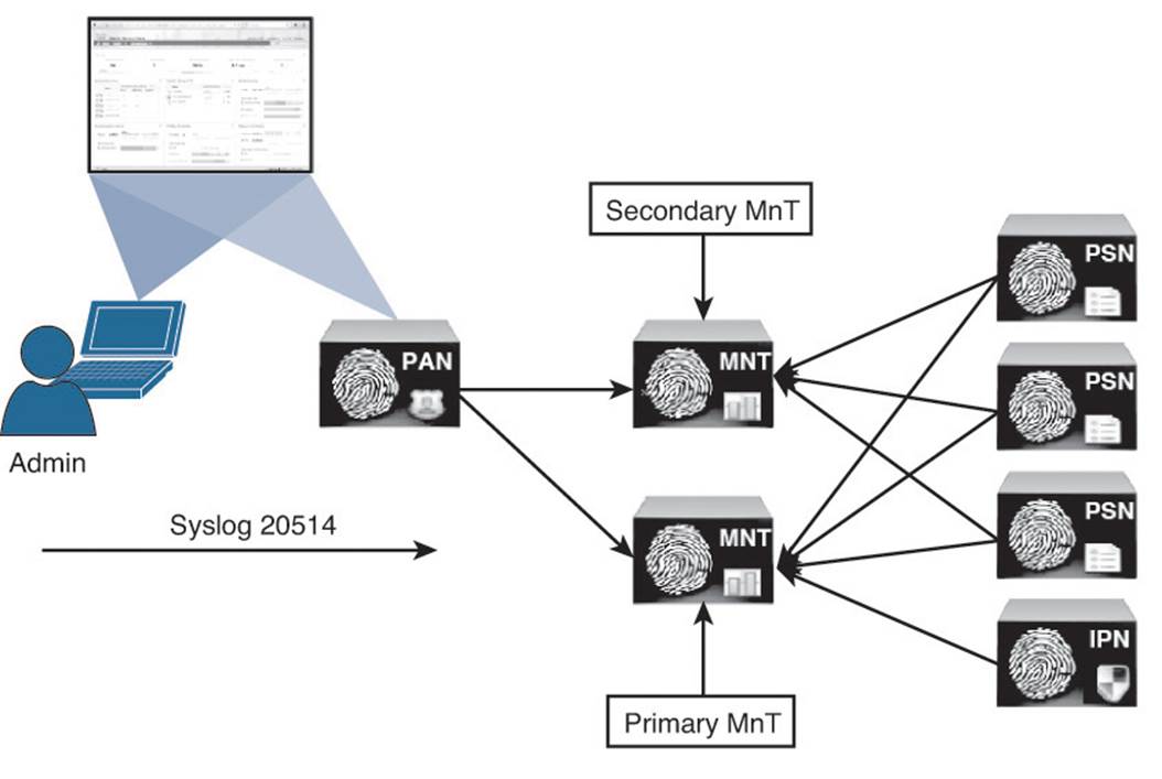
Figure 21-8 Logging flows.
Note
Inline posture nodes (IPNs) send syslog to only a single target.
The active/active nature of the MnT nodes can be viewed easily in the administrative console under Administration > System > Logging > Remote Logging Targets. Figure 21-9 shows the two MnTs being defined as LogCollector and LogCollector2.
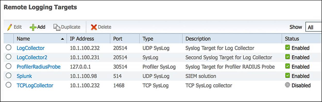
Figure 21-9 Logging targets.
You’ll notice within Administration > System > Logging > Logging Categories that both LogCollector and LogCollector2 are automatically listed as targets for the logs, as shown in Figure 21-10. This ensures all ISE nodes in the cube send logs to both MnT nodes.
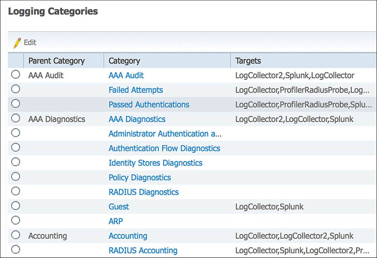
Figure 21-10 Logging categories.
Upon an MnT failure, all nodes will continue to send logs to the remaining MnT node. Therefore, no logs are lost. The PAN will retrieve all log and report data from the secondary MnT node, so no administrative function loss occurs, either. However, the log database is not synchronized between the primary and secondary MnT nodes. Therefore, when the MnT node returns to service, a backup and restore of the monitoring node is required to keep the two MnT nodes in complete sync.
Note
The best practice for logging is to also send logging data to a security information manager (SIM) tool for long-term data archiving and reporting.
Policy Administration Nodes
The policy administration node is not only responsible for providing an administrative GUI for ISE, but is also responsible for the critical function of database synchronization of all ISE nodes. All ISE nodes maintain a full copy of the database, with the master database existing on the primary PAN.
A policy services node can get new data about an endpoint, and when that occurs it must sync that data to the primary PAN. The primary PAN then synchronizes that data out to all the ISE nodes in the deployment. Because the PAN can have many updates to send to each node, those nodes must acknowledge the last update before a new update can be sent.
Because the functionality is so arduous and it is absolutely critical to have only a single source of truth for the data in the database, it is a manual process to fail over to the secondary PAN. In the event of the primary PAN going offline, no synchronizations will occur until the secondary PAN is promoted to primary. After it becomes the primary, it will take over all synchronization responsibility. Some might consider this a “warm spare” type of high availability (HA).
To promote the secondary PAN to the primary role, connect to the GUI on the secondary PAN by doing the following:
Step 1. Navigate to Administration > System > Deployment.
Step 2. Click Promote to Primary, as shown in Figure 21-11.
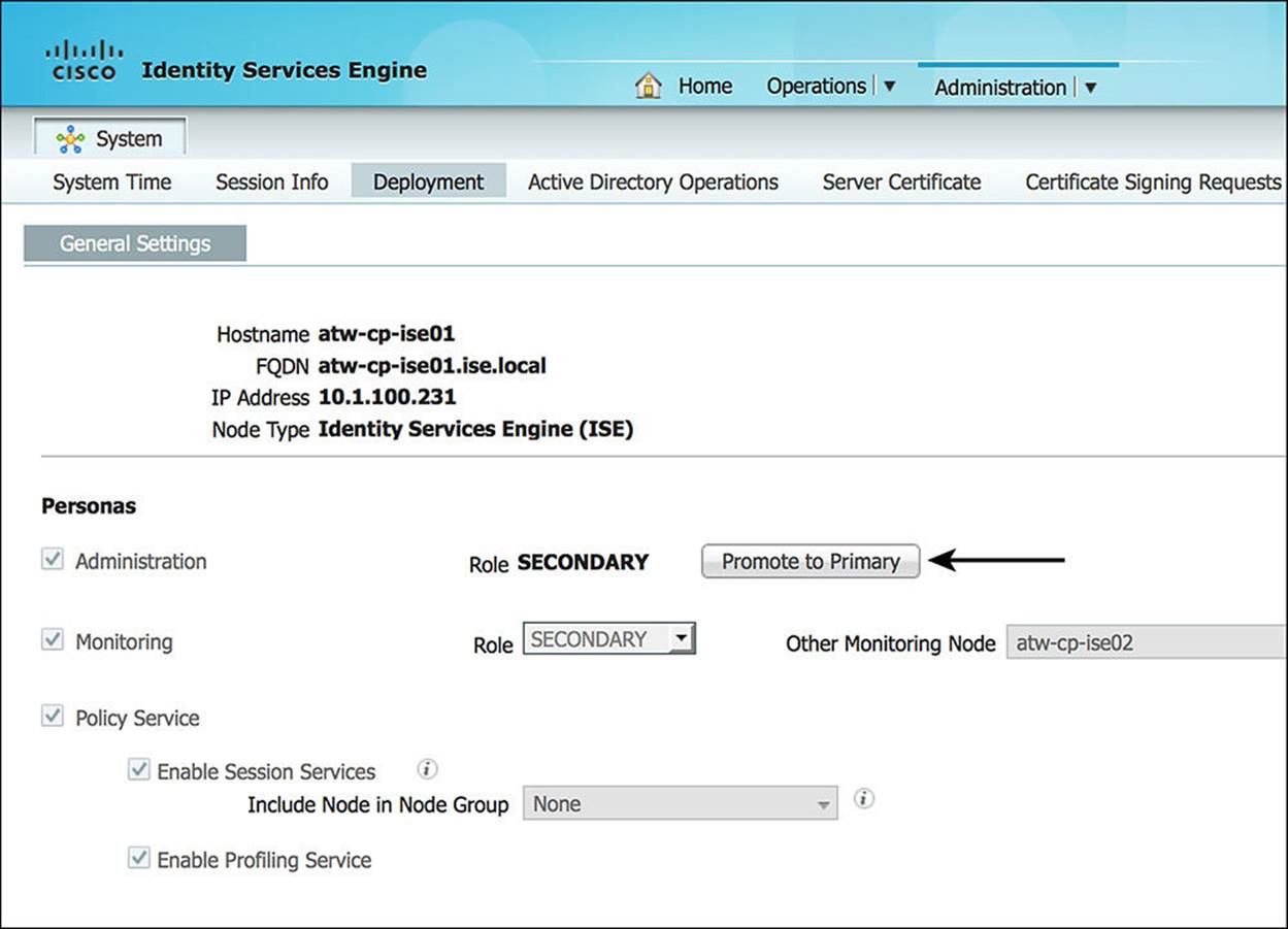
Figure 21-11 Promote to primary.
Node Groups
PSNs do not necessarily need to have an HA type of configuration. Every ISE node maintains a full copy of the database, and the NADs have their own detection of a “dead” RADIUS server, which triggers the NAD to send AAA communication to the next RADIUS server in the list.
However, ISE does have a concept of a node group. Node groups are made up of Layer-2 adjacent (same VLAN) PSNs, where the nodes maintain a heartbeat with each other. In the event that a PSN goes down while a session is being authenticated, one of the other PSNs in the node group sends a CoA to the NAD so the endpoint can restart the session establishment with a new PSN.
This is most commonly used when deploying the PSNs behind a load balancer. However, there is no requirement for node groups to be used solely with any Layer-2 adjacent PSNs.
To configure a node group, do the following:
Step 1. Navigate to Administration > System > Deployment.
Step 2. On the left side, click the cog and select Create Node Group, as shown in Figure 21-12.
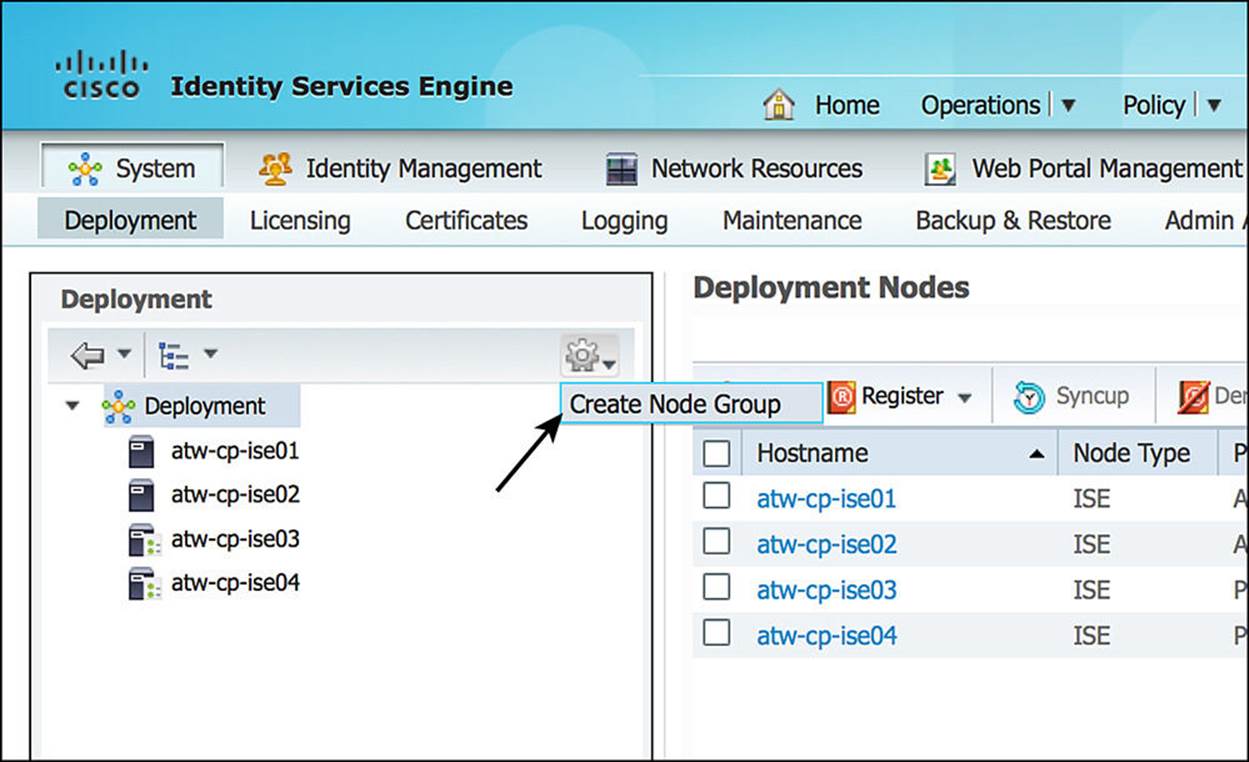
Figure 21-12 Create node group.
Step 3. Enter a name for the node group. Use a name that also helps describe the location of the group.
Step 4. Enter a more detailed description, helping to identify exactly where the node group is—for example, DataCenter 1 Node Group.
Step 5. Select a multicast address for keep-alive communication. As the screen dictates, ensure it is not a multicast address already in use, as shown in Figure 21-13.
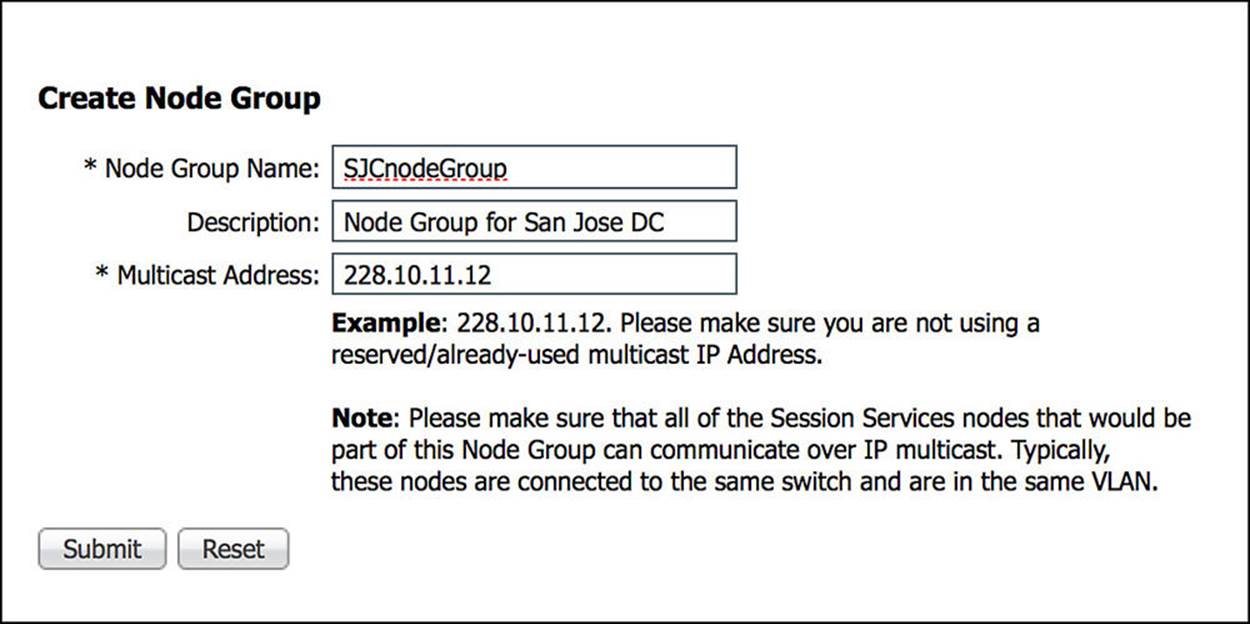
Figure 21-13 Node group creation.
Step 6. Click OK on the success pop-up window. You will also notice the appearance of the node group on the left side.
Now that the node group exists, it’s time to add the PSNs to the node group.
Step 7. Navigate to Administration > System > Deployment.
Step 8. Select one of the PSNs to add to the node group.
Step 9. Click the node group drop-down and select the newly created group, as shown in Figure 21-14.
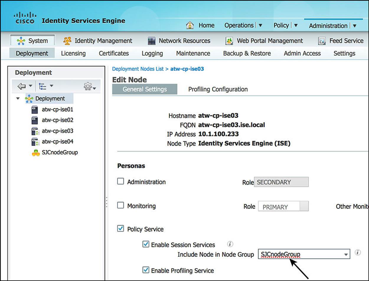
Figure 21-14 Assign node group.
Step 10. Click Save.
Step 11. Repeat steps 7-10 for each PSN that should be part of the node group. Figure 21-15 shows the final deployment tree after the two PSNs (atw-cp-ise03 and atw-cp-ise04) are added to the node group.
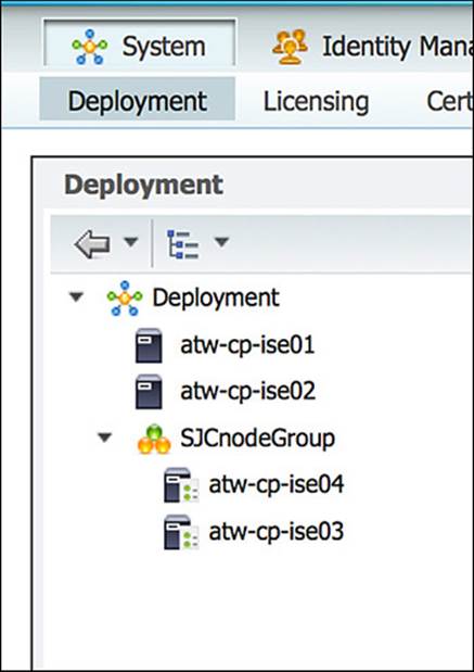
Figure 21-15 Deployment tree.
Using Load Balancers
A somewhat controversial and often debated topic is the use of load balancers with ISE policy services nodes. The reason that this becomes controversial is due to the server load balancer teams being used to installing using a certain architecture and the ISE solution requiring a different architecture.
The first question is usually why? Ultimately, the complexities with load balancing are related to the many types of traffic that must flow between the endpoint and the active PSN.
General Guidelines
There are a few general guidelines to follow when using a load balancer. Of course, a specific design can and will get more specific and more detailed than this list, but overall the rules of thumb are as follows:
![]() Each PSN must be reachable by the PAN/MnT directly, without having to go through NAT.
Each PSN must be reachable by the PAN/MnT directly, without having to go through NAT.
![]() This can sometimes be referred to as Routed Mode or Pass-Through Mode.
This can sometimes be referred to as Routed Mode or Pass-Through Mode.
![]() You cannot use Source NAT (SNAT). ISE uses the Layer-3 address to identify the NAD, not the NAS-IP address in the RADIUS packet.
You cannot use Source NAT (SNAT). ISE uses the Layer-3 address to identify the NAD, not the NAS-IP address in the RADIUS packet.
![]() SNAT would hide the real IP address of the switch and NAT it to a VIP address. Therefore, you cannot use Source NAT in the load balancer design.
SNAT would hide the real IP address of the switch and NAT it to a VIP address. Therefore, you cannot use Source NAT in the load balancer design.
![]() Each PSN must also be reachable directly from the endpoint.
Each PSN must also be reachable directly from the endpoint.
![]() When the PSN sends a URL redirection to the NAD, it will use the FQDN from the ISE node’s configuration (that is, atw-cp-ise03.ise.local), not the IP address of the VIP.
When the PSN sends a URL redirection to the NAD, it will use the FQDN from the ISE node’s configuration (that is, atw-cp-ise03.ise.local), not the IP address of the VIP.
![]() The certificates used on the PSNs should include a DNS name in the subject alternative name (SAN) field that resolves to the IP address of the VIP.
The certificates used on the PSNs should include a DNS name in the subject alternative name (SAN) field that resolves to the IP address of the VIP.
![]() For example, ise.company.com
For example, ise.company.com
![]() The load-balancing rules must ensure that the same PSN is used for the entire session.
The load-balancing rules must ensure that the same PSN is used for the entire session.
![]() Use persistence, sometimes called “sticky” based on Calling-Station-ID and Framed-IP-address.
Use persistence, sometimes called “sticky” based on Calling-Station-ID and Framed-IP-address.
![]() Some load balancers have built-in intelligence that allows the same persistence value to persist across both RADIUS and DHCP. This should be used if the capability exists.
Some load balancers have built-in intelligence that allows the same persistence value to persist across both RADIUS and DHCP. This should be used if the capability exists.
![]() The virtual IP (VIP) will be listed as the RADIUS server of each NAD for all 802.1X-related AAA.
The virtual IP (VIP) will be listed as the RADIUS server of each NAD for all 802.1X-related AAA.
![]() Includes both authentication and accounting packets.
Includes both authentication and accounting packets.
![]() Some load balancers use a separate VIP for each protocol type.
Some load balancers use a separate VIP for each protocol type.
![]() The list of RADIUS servers allowed to perform dynamic authorizations (CoA) on the NAD should use the real IP addresses of the PSNs.
The list of RADIUS servers allowed to perform dynamic authorizations (CoA) on the NAD should use the real IP addresses of the PSNs.
![]() If the load balancer is capable of using NAT for the PSN IP address for the CoA traffic destined to the network device, then only the VIP IP address would need to be included in the list of dynamic authorization (CoA).
If the load balancer is capable of using NAT for the PSN IP address for the CoA traffic destined to the network device, then only the VIP IP address would need to be included in the list of dynamic authorization (CoA).
![]() The load balancer(s) will also get listed as NADs in ISE so their test authentications can be answered.
The load balancer(s) will also get listed as NADs in ISE so their test authentications can be answered.
![]() Load balancers should be configured to use test probes to ensure the PSNs are still “alive and well.”
Load balancers should be configured to use test probes to ensure the PSNs are still “alive and well.”
![]() A probe should be configured to ensure RADIUS is responding.
A probe should be configured to ensure RADIUS is responding.
![]() HTTPS should also be checked.
HTTPS should also be checked.
![]() If either probe fails, the PSN should be taken out of service.
If either probe fails, the PSN should be taken out of service.
Failure Scenarios
If a single PSN fails, the load balancer should take that PSN out of service and spread the load over the remaining PSNs. When the failed PSN is returned to service, the load balancer will add it back into the rotation. By using node groups along with a load balancer, one of the other node group members will issue a CoA-reauth for any sessions that were establishing. This CoA will cause the session to begin again. At this point, the load balancer should direct the new authentication to a different PSN.
NADs have some built-in capabilities to detect when the configured RADIUS server is “dead” and automatically fail over to the next RADIUS server configured. When using a load balancer, the RADIUS server IP address is actually the VIP address. So, if the entire VIP is unreachable (that is, the load balancer has died), the NAD should quickly fail over to the next RADIUS server in the list. That RADIUS server could be another VIP in a second datacenter or another backup RADIUS server.
IOS Load Balancing
Cisco network devices have a lot of intelligence built in to them to aid in an intelligent access layer for policy and policy enforcement. One such intelligence level is the ability to perform local load-balancing of RADIUS servers. This does not mean using a Cisco switch as a server load balancer, instead of a dedicated appliance.
What it’s referring to is the ability of the access layer switch to load-balance the outbound authentication requests for endpoints that are authenticated to the switch itself, as illustrated in Figure 21-16.
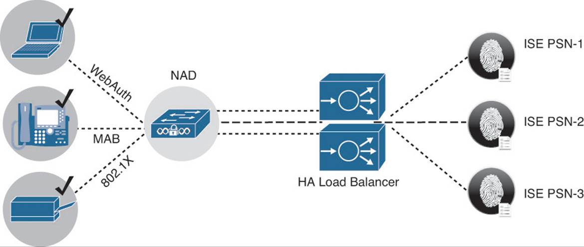
Figure 21-16 IOS load-balancing.
Enabling IOS RADIUS server load-balancing takes only one additional command. After all the PSNs are defined as AAA servers in the switch, use the radius-server load-balance global configuration command to enable it.
Example 21-3 shows use of a show command to verify that multiple ISE servers are configured. Example 21-4 shows how to enable the RADIUS server load-balancing.
Example 21-3 Verifying That All ISE PSNs Are Configured on Switch
3750-X#show aaa server | i host
RADIUS: id 4, priority 1, host 10.1.100.232, auth-port 1812, acct-port 1813
RADIUS: id 5, priority 2, host 10.1.100.233, auth-port 1812, acct-port 1813
RADIUS: id 6, priority 3, host 10.1.100.234, auth-port 1812, acct-port 1813
Example 21-4 The Enabling of IOS Load-Balancing
Example 21-4 Enabling IOS Load Balancing
3750-X(config)# radius-server load-balance method least-outstanding batch-size 5
Maintaining ISE Deployments
Although having a distributed deployment and load-balanced architecture is certainly critical items to scaling the deployment and ensuring it is highly available, there are critical basic maintenance items that should always be considered to ensure the most uptime and stability.
That means having a patching as well as a backup and restore strategy.
Patching ISE
ISE patches are released roughly once per month. These patches contain bug fixes as well as security fixes when necessary. Think about the Heartbleed and Poodle vulnerabilities that were recently discovered with SSL. To ensure that bug fixes are applied, security vulnerabilities are plugged, and the solution will work as seamlessly as possible, always have a planned patching strategy.
Patches are downloaded from cisco.com and are found under Downloads > Products > Security > Access Control and Policy > Identity Services Engine > Identity Services Engine Software, as shown at the top of Figure 21-17.
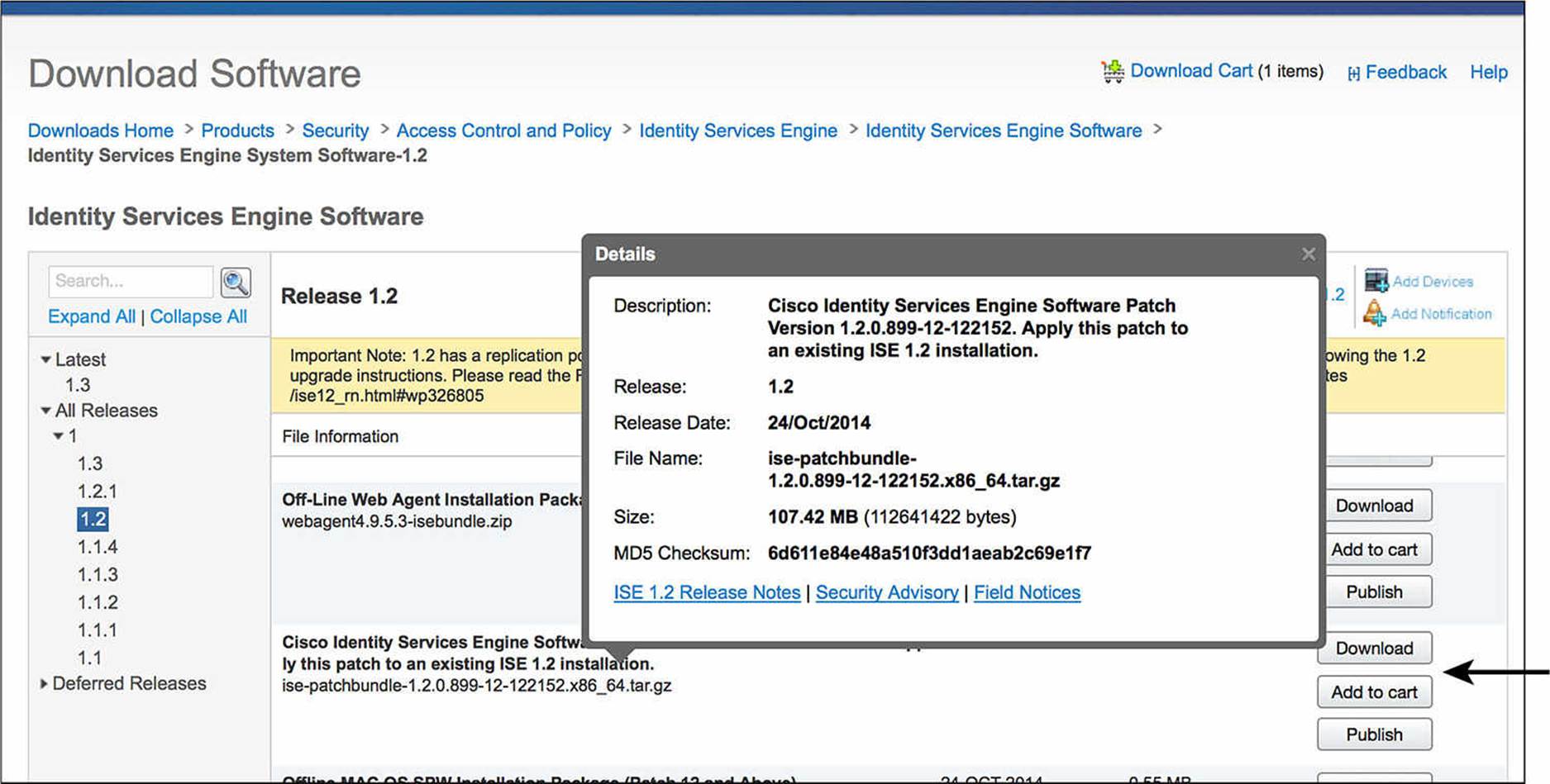
Figure 21-17 ISE Downloads page.
Search the list of software available for your specific version of ISE. Figure 21-18 illustrates the naming convention for ISE patches. Cisco ISE patches are normally cumulative, meaning that installing 1.2 patch 12 will include all the fixes in patches 1-11 as well. The following steps walk you through ISE patching.
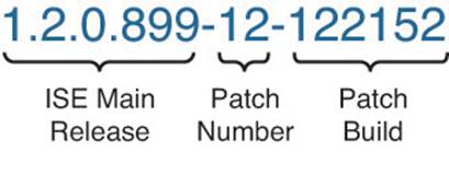
Figure 21-18 Anatomy of ISE patch nomenclature.
Step 1. Download the required patch.
Step 2. From the ISE GUI, navigate to Administration > System > Maintenance > Patch Management.
Step 3. Click the Install button, as shown in Figure 21-19.
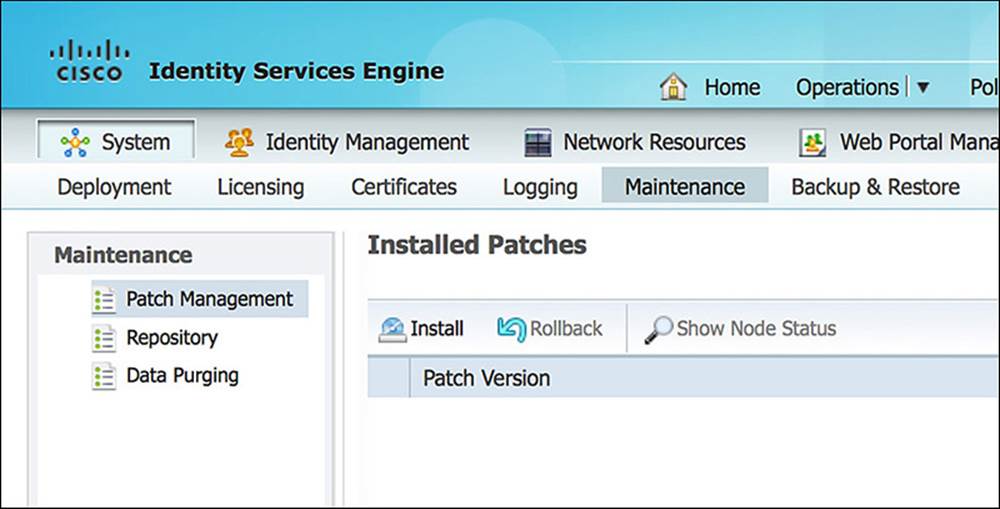
Figure 21-19 Patch Management screen.
Step 4. Click Browse, select the downloaded patch, and click Install, as shown in Figure 21-20.
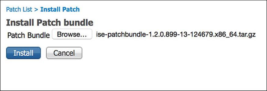
Figure 21-20 Install the selected patch.
The patch bundle is now uploaded through the web UI, and you are prompted to confirm the MD5 hash of the file, as shown in Figure 21-21.
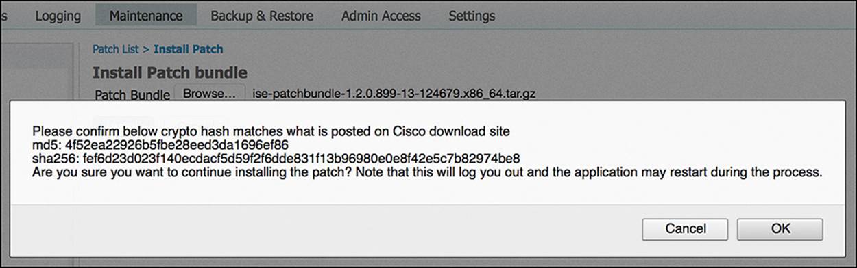
Figure 21-21 Verify MD5 hash.
Step 5. Click OK if the MD5 hash matches.
As the patch is installed on the PAN, you are logged out of the GUI and the patch is distributed from the PAN to all nodes in the ISE cube. The patch will be applied to all nodes in the cube one at a time, in alphabetical order.
You can log back in to the PAN when it’s finished restarting services or rebooting. Use the Show Node Status button shown in Figure 21-19 to verify the progress of the patching. Figure 21-22 shows the resulting status of each nodes progress for the patch installation.
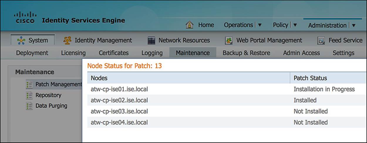
Figure 21-22 Node status.
Backup and Restore
Another key strategy to ensuring the availability of ISE in the environment is having a solid backup strategy. There are two types of ISE backups: configuration and operational backup. These two types are most easily related to backing up the product databases (configuration) and the MnT data (operational).
Figure 21-23 shows the backup screen in ISE, located at Administration > System > Backup & Restore.
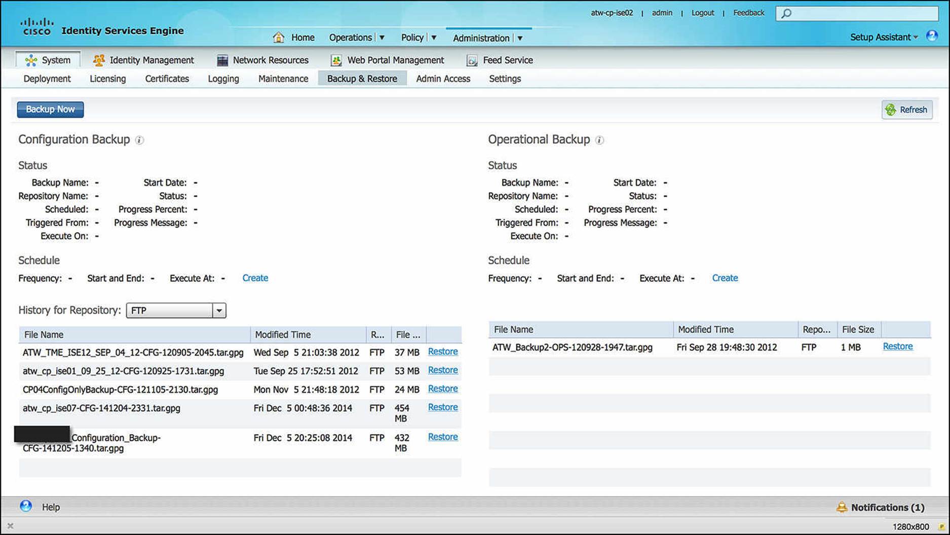
Figure 21-23 Backup and Restore screen.
As shown in Figure 21-23, the backups are stored in a repository and can be restored from the same repository. Backups can be scheduled or run on demand. The status of a backup can be viewed from the GUI or the CLI, but the status of a restore can be viewed only from the CLI.
Exam Preparation Tasks
Review All Key Topics
Review the most important topics in the chapter, noted with the key topics icon in the outer margin of the page. Table 21-4 lists a reference of these key topics and the page numbers on which each is found.
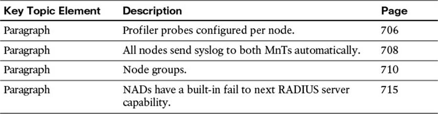
Table 21-4 Key Topics for Chapter 21
Define Key Terms
Define the following key terms from this chapter and check your answers in the glossary:
node groups
All materials on the site are licensed Creative Commons Attribution-Sharealike 3.0 Unported CC BY-SA 3.0 & GNU Free Documentation License (GFDL)
If you are the copyright holder of any material contained on our site and intend to remove it, please contact our site administrator for approval.
© 2016-2026 All site design rights belong to S.Y.A.