CompTIA Network+ N10-006 Cert Guide (2015)
Chapter 13. Network Troubleshooting
After completion of this chapter, you will be able to answer the following questions:
![]() What are the elements in a structured troubleshooting model?
What are the elements in a structured troubleshooting model?
![]() What common physical layer troubleshooting issues might you encounter?
What common physical layer troubleshooting issues might you encounter?
![]() What potential Layer 2 issues are you most likely to face when troubleshooting a network containing Ethernet switches?
What potential Layer 2 issues are you most likely to face when troubleshooting a network containing Ethernet switches?
![]() Aside from routing protocol troubleshooting, what Layer 3 troubleshooting issues are common in a routed network?
Aside from routing protocol troubleshooting, what Layer 3 troubleshooting issues are common in a routed network?
![]() How do characteristics unique to wireless networks impact your troubleshooting of a network containing wireless access points?
How do characteristics unique to wireless networks impact your troubleshooting of a network containing wireless access points?
As you perform your day-to-day tasks of administering a network, a significant percentage of your time will be dedicated to resolving network issues. Whether the issues that you are troubleshooting were reported by an end user or were issues you discovered, you need an effective plan to respond to those issues. Specifically, you need a systematic approach to clearly articulate the issue, gather information about the issue, hypothesize the underlying cause of the issue, validate your hypothesis, create an action plan, implement that action plan, observe results, and document your resolution. Without a plan, your efforts might be inefficient, as you try one thing after another, possibly causing other issues in the process.
Although your troubleshooting efforts can most definitely benefit from a structured approach, realize that troubleshooting is part art and part science. Specifically, your intuition and instincts play a huge role in isolating an issue. Of course, those skills are developed over time and come with experience and exposure to more and more scenarios.
To help you start developing, or continue honing, your troubleshooting skills, this chapter begins by presenting you with a formalized troubleshooting methodology, which can act as a guide for addressing most any network issue. Then the remainder of this chapter presents you with a collection of common network issues to consider in your real-world troubleshooting efforts (and issues to consider on the Network+ exam).
These common network issues are broken down into the following categories: physical layer issues, data link layer issues, network layer issues, and wireless network issues.
Foundation Topics
Troubleshooting Basics
Troubleshooting network issues is implicit in the responsibilities of a network administrator. Such issues could arise as a result of human error (for example, a misconfiguration), equipment failure, software bugs, or traffic patterns (for example, high utilization or a network being under attack by malicious traffic).
Many network issues can be successfully resolved using a variety of approaches. This section begins by introducing you to troubleshooting fundamentals. Then you are presented with a structured troubleshooting methodology you should know for the Network+ exam.
Troubleshooting Fundamentals
The process of troubleshooting, at its essence, is the process of responding to a problem report (sometimes in the form of a trouble ticket), diagnosing the underlying cause of the problem, and resolving the problem. Although you normally think of the troubleshooting process beginning when a user reports an issue, realize that through effective network monitoring, you might detect a situation that could become a troubleshooting issue and resolve that situation before it impacts users.
After an issue is reported, the first step toward resolution is clearly defining the issue. After you have a clearly defined troubleshooting target, you can begin gathering information related to that issue. Based on the information collected, you might be able to better define the issue. Then you hypothesize the likely causes of the issue. Evaluation of these likely causes leads to the identification of the suspected underlying root cause of an issue.
After a suspected underlying cause is identified, you define approaches to resolve an issue and select what you consider to be the best approach. Sometimes the best approach to resolving an issue cannot be implemented immediately. For example, a piece of equipment might need replacing. However, implementing such an approach during working hours might disrupt a business’s workflow. In such situations, a troubleshooter might use a temporary fix until a permanent fix can be put in place.
As a personal example, when helping troubleshoot a connectivity issue for a resort hotel at a major theme park, my coworkers and I discovered that a modular Ethernet switch had an issue causing Spanning Tree Protocol (STP) to fail, resulting in a Layer 2 loop. This loop flooded the network with traffic, preventing the hotel from issuing keycards for guest rooms. The underlying cause was clear. Specifically, the Ethernet switch had a bad module. However, the time was about 4:00 p.m., a peak time for guest registration. So, instead of immediately replacing the faulty module, we disconnected one of the redundant links, thus breaking the Layer 2 loop. The logic was that it was better to have the network function at this time without STP than for the network to experience an even longer outage while the bad module was replaced. Late that night, someone came back to the switch and swapped out the module, resolving the underlying cause while minimizing user impact.
Consider Figure 13-1, which depicts a simplified model of the troubleshooting steps previously described. This simplified model consists of three steps:
Step 1 Problem report
Step 2 Problem diagnosis
Step 3 Problem resolution


Figure 13-1 Simplified Troubleshooting Flow
Of these three steps, the majority of a troubleshooter’s efforts are spent in the problem diagnosis step. Table 13-1 describes key components of this diagnosis step.
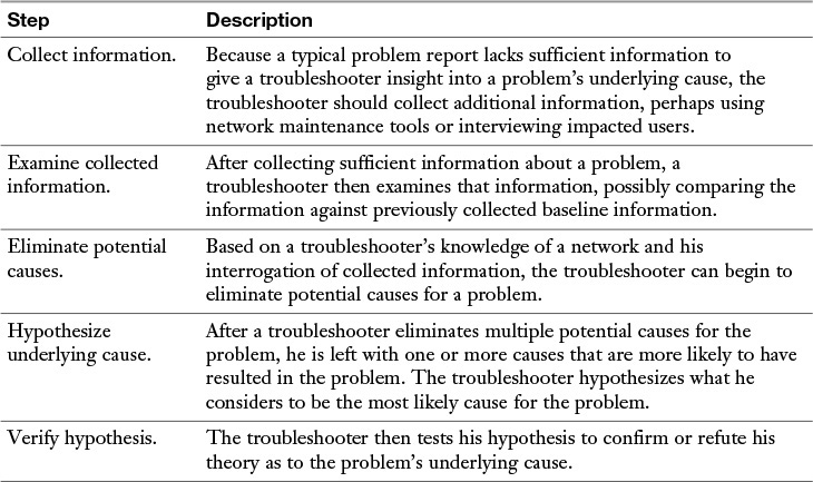
Table 13-1 Steps to Diagnose a Problem
Structured Troubleshooting Methodology
Troubleshooting skills vary from administrator to administrator. Therefore, although most troubleshooting approaches include the collection and analysis of information, elimination of potential causes, hypothesis of likely causes, and testing of the suspected cause, different troubleshooters might spend different amounts of time performing these tasks.
If a troubleshooter does not follow a structured approach, the temptation is to move between the previously listed troubleshooting tasks in a fairly random way, often based on instinct. Although such an approach might well lead to a problem resolution, it can become confusing to remember what you have tried and what you have not tried. Also, if another administrator comes to assist you, communicating to that other administrator the steps you have already gone through could be a challenge. Therefore, following a structured troubleshooting approach not only helps prevent your trying the same thing more than once and inadvertently skipping a task but also aids in communicating to someone else the possibilities you already eliminated.
You might encounter a variety of structured troubleshooting methodologies in networking literature. However, for the Network+ exam, the methodology shown in Figure 13-2 is what you should memorize.
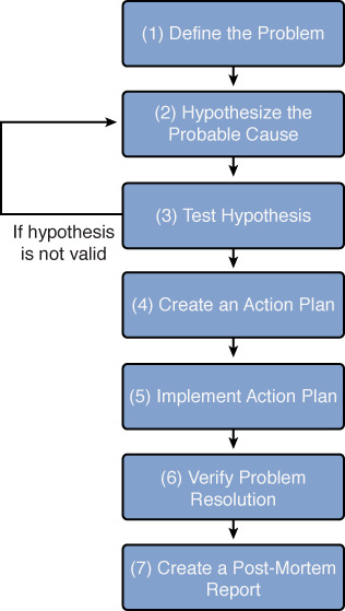
Figure 13-2 Structured Troubleshooting Approach
The following is an elaboration on this seven-step methodology:
Step 1 Define the problem. Effective troubleshooting begins with a clear problem definition. This definition might include specific symptoms, such as, “User A’s computer is unable to communicate with server 1 (as verified by a ping test). However, user A can communicate with all other servers. Also, no other user seems to have an issue connecting to server 1.” This problem definition might come from questioning the impacted user(s) and doing your own testing (for example, seeing if you can ping from user A’s computer to server 1). If possible, determine whether anything has changed in the network (or in the computer) configuration. Also, find out whether this is a new installation, which has never worked in the past.
Step 2 Hypothesize a probable cause. This is the point in the troubleshooting process where your experience and intuition can be extremely helpful because you are now going to brainstorm a list of possible causes. When examining your collected data (for example, output from the ipconfig /all command), question everything. For example, you might think that the issue described in Step 1 could result from causes such as an ACL blocking traffic to or from the PC, a connectivity issue with the PC or server, or an incorrect IP address configuration on the PC. From your list of possible causes, select the one that you consider the most likely. From the previous list, you might believe that an incorrect IP address configuration on the PC is the most likely cause of the problem. Specifically, you conclude that the issue is not related to connectivity because other PCs can get to the server, and user A’s PC can get to other servers. Also, you conclude that it is more likely that user A’s PC has a bad IP-address configuration than for an ACL to have been administratively added to the router to only block traffic between user A’s PC and server 1.
Step 3 Test the hypothesis. Before taking action on what you consider to be the most likely cause of a problem, do a sanity check on your theory. Would your hypothesized cause lead to the observed symptoms? In the example presented in the preceding steps, you might examine the subnet mask assigned to user A’s computer and determine that it is incorrect. Specifically, the subnet mask makes user A’s computer think that server 1 is on the same subnet as user A’s computer. As a result, user A’s computer does not forward traffic to its default gateway when attempting to reach server 1. If your hypothesis is technically sound, you can proceed to Step 4. However, if you notice a flaw in your logic, you need to formulate an alternate hypothesis. The formation of an alternate hypothesis might involve escalating the problem to someone more familiar with the device(s) in question.
Step 4 Create an action plan. Now that you have confirmed that your theory makes sense technically, the time has come to develop an action plan. If time permits, you should document your action plan. The documentation of your action plan can be used as a back-out plan if your hypothesis is incorrect. In the example we have been building on throughout these steps, an action plan might be to change the subnet mask on user A’s computer from 255.255.0.0 to 255.255.255.0.
Step 5 Implement action plan. Based on your documented plan of action, you should schedule an appropriate time to implement your action plan. The selection of an appropriate time is a balance between the severity of a problem and the impact your action plan will have on other users. Sometimes, when attempting to implement your action plan, you realize that you do not have sufficient administrative privileges to perform a task in your action plan. In such cases, you should escalate the issue to someone with appropriate administrative rights. In this example, changing the subnet mask on one computer should not impact any other devices. So, you might immediately make the configuration change on user A’s computer.
Step 6 Verify problem resolution. After implementing your action plan, you need to verify that the symptoms listed in your original problem definition are gone. Also, attempt to determine whether your action plan has caused any other issues on the network. A mistake many troubleshooters make at this point is believing that the issue has been resolved because the specific symptom (or symptoms) they were looking for is gone. However, the user who originally reported the issue might still be having a problem. Therefore, troubleshooters should live by this mantra: “A problem isn’t fixed until the user believes it’s fixed.” So, you should always get confirmation from the person reporting an issue that, from her perspective, the reported issue has indeed been resolved. In our example, you could attempt to ping server 1 from user A. If the ping is successful, check with user A to see whether she agrees that the problem is resolved.
Step 7 Create a post-mortem report. A post-mortem report is a document that describes the reported issue, its underlying causes, and what was done to resolve the issue. This report might be useful when troubleshooting similar issues in the future.
Keep in mind when working your way through the previous steps that you might encounter an issue that you do not have sufficient information to solve. When that happens, you might need to further research the issue yourself. However, if time is of the essence, you might need to immediately escalate the issue to someone else within your organization, to an equipment vendor, or to an outside consultant.
Physical Layer Troubleshooting
Layer 1 (the physical layer) of the OSI model is foundational to all the other layers. As a result, if Layer 1 isn’t functioning, none of the upper layers will function properly. Table 13-2 presents a collection of common Layer 1 issues.
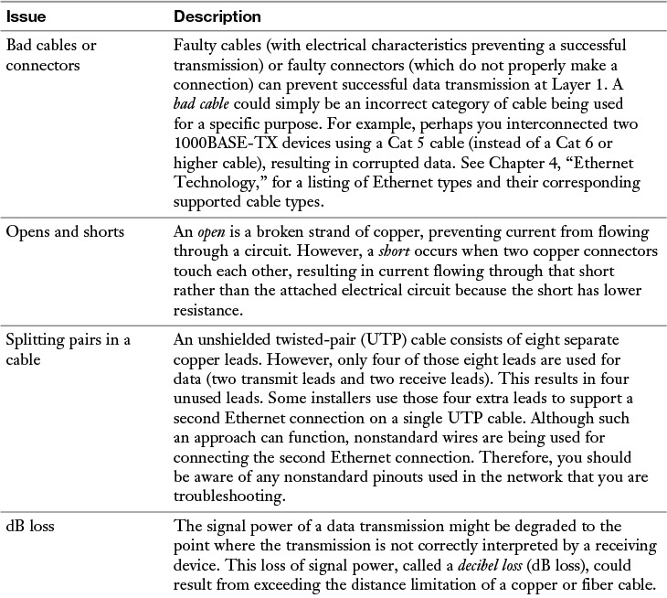
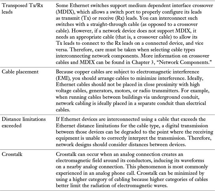
Table 13-2 Common Layer 1 Troubleshooting Issues
Note
Many of these issues have been discussed in previous chapters.
Physical Layer Troubleshooting: Scenario
To practice your physical layer troubleshooting skills, consider the network diagram presented in Figure 13-3.
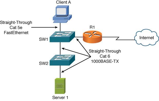
Figure 13-3 Physical Layer Troubleshooting: Sample Topology
Assume that both switches in Figure 13-3 are capable of autonegotiating Ethernet speeds of 10, 100, or 1000 Mbps. Also, assume the switches do not support MDIX. Based on the provided information, take a moment (before reading on) and identify what you believe to be a Layer 1 issue in the topology.
Physical Layer Troubleshooting: Solution
In the topology shown in Figure 13-3, notice that switches SW1 and SW2 are interconnected with a straight-through cable. Also, recall that neither switch supports MDIX. As a result, the ports interconnecting the two switches have their Tx leads interconnected and their Rx leads interconnected. As a result, no communication is possible. The resolution to such a scenario is to replace the straight-through Cat 6 cable between SW1 and SW2 with a crossover Cat 6 cable.
Physical copper cable issues could include shorts, opens, incorrect cabling, EMI/RFI, attenuation, cross-talk, bad connector, bad cable, or using too long of a run.
Physical fiber cable issues could include attenuation, connector mismatch, wavelength mismatch, fiber type mismatch, dirty connector, extreme bends in fiber, or trying to use too long of a fiber cable based on the specifications for that fiber.
You can use the testing tools discussed in Chapter 11, “Network Management,” to troubleshoot cable-related problems for copper and fiber.
Data Link Layer Troubleshooting
Most enterprise LANs rely on some form of Ethernet technology (for example, Ethernet, Fast Ethernet, or Gigabit Ethernet). Therefore, an understanding of Ethernet switch operation, at Layer 2 (that is, the data link layer), is critical to troubleshooting many LAN issues. You might want to reference Chapter 4 for a review of Ethernet switch operation.
Table 13-3 presents a collection of common Layer 2 issues.
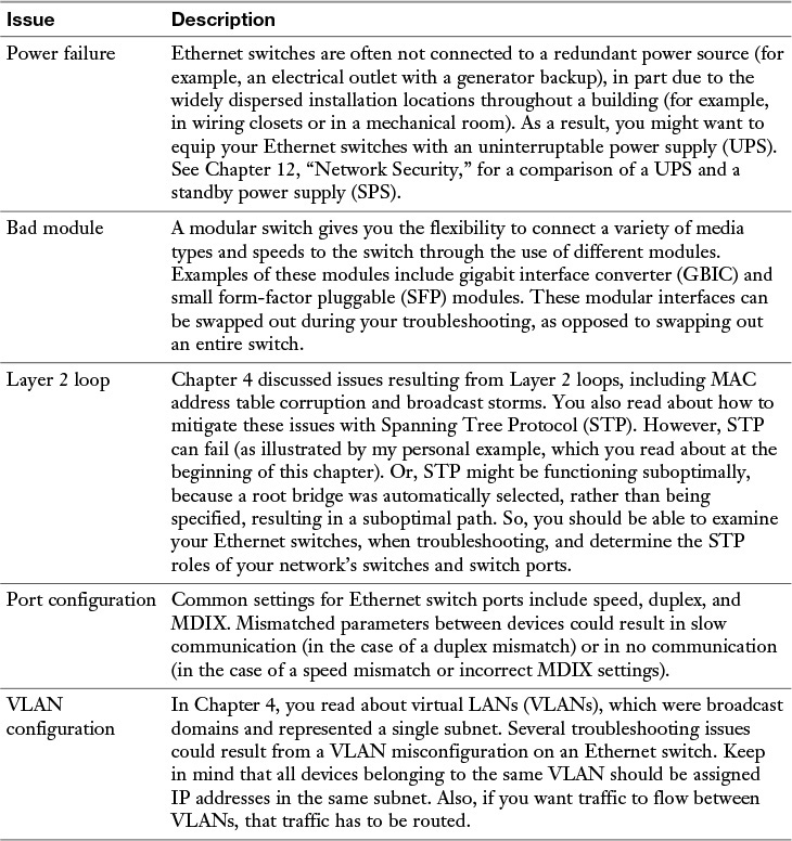
Table 13-3 Common Layer 2 Troubleshooting Issues
Data Link Layer Troubleshooting: Scenario
Based on your knowledge of an Ethernet switch (a common example of a data link layer device), consider the following troubleshooting scenario. The network depicted in Figure 13-4 is having an issue. Specifically, client A is not able to communicate with server 1. Based on the diagram, what do you consider to be the most likely cause?
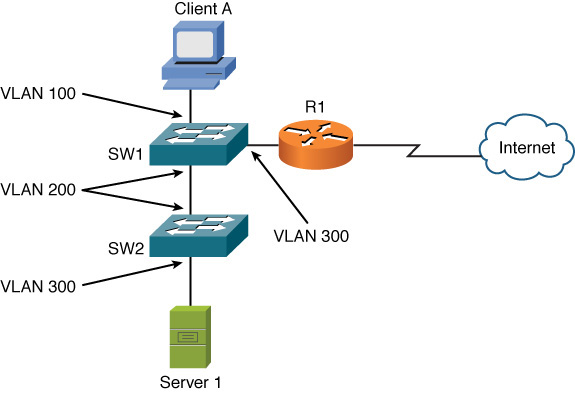
Figure 13-4 Data Link Layer Troubleshooting: Sample Topology
After determining what you believe to be the underlying cause, check your answer with the following solution.
Data Link Layer Troubleshooting: Solution
Even though client A and server 1, as shown in Figure 13-4, are on the same VLAN (VLAN 100), there is no VLAN 100 traffic flowing between switches SW1 and SW2. Specifically, the connection linking SW1 and SW2 only carries traffic for VLAN 200. A couple of solutions exist.
One solution is to change the ports on switches SW1 and SW2 to both belong to VLAN 100. Another solution is to configure an IEEE 802.1Q trunk to interconnect SW1 and SW2 because a trunk can simultaneously carry traffic for multiple VLANs.
Network Layer Troubleshooting
When troubleshooting connectivity issues for an IP-based network, the network layer (Layer 3) is often an appropriate place to begin your troubleshooting efforts. For example, if you are experiencing connectivity issues between two hosts on a network, you could check Layer 3 by pinging from one host to another. If the pings are successful, you can conclude that the issue resides above Layer 3 (Layers 4–7). However, if the pings fail, you can focus your troubleshooting efforts on Layers 1–3. The rationale for this conclusion is based on ping using Internet Control Message Protocol (ICMP), which is a Layer 4 protocol. If one Layer 4 protocol is functioning correctly (even though other Layer 4 protocols might be having issues), you can conclude that Layers 1–3 are operational.
Layer 3 Data Structures
As traffic is routed through a network, routers encountered along the way from the source to the destination need consistency in how they route traffic. For example, if one router selected the best path based on hop count, and another router selected the best path based on a link’s bandwidth, a routing loop could conceivably occur. Fortunately, having a common routing protocol configured on all routers within a topology helps ensure consistency in routing decisions.
That is not to say that a topology could not have more than one routing protocol. You could strategically redistribute routes between different routing protocols. Also, static routes could be used in conjunction with dynamic routing protocols. However, care must be taken in environments with redundant links and multiple routing protocols to avoid potential routing loops.
To better troubleshoot specific dynamic routing protocols, let’s first generically consider how dynamic routing protocols’ data structures interact with a router’s IP routing table.
Figure 13-5 shows the interaction between the data structures of an IP routing protocol and a router’s IP routing table. Realize, however, that not all routing protocols maintain their own data structures. For example, RIP is a routing protocol that works directly with an IP routing table in a router, rather than maintaining a separate data structure.
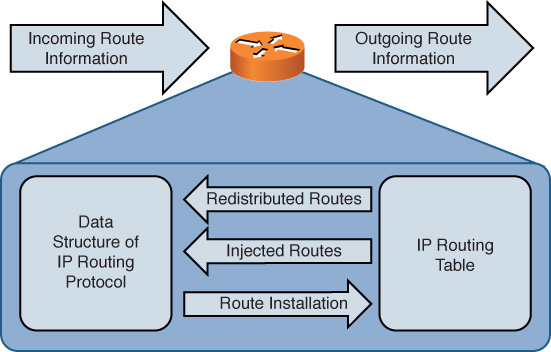
Figure 13-5 Interaction Between IP Routing Protocol Data Structures and IP Routing Tables
As a router receives route information from a neighboring router, that information is stored in the data structures of the IP routing protocol (if the IP routing protocol uses data structures). A data structure might also be populated by the local router. For example, a router might be configured for route redistribution where route information is redistributed by a routing information source (for example, a dynamic routing protocol, a static route, or a connected route). Also, the router might be configured to have specific interfaces participate in an IP routing protocol.
The data structure analyzes all the information it receives to select the best route to a certain network. This best route is determined by looking for the route with the best metric. The data structure of an IP routing protocol then injects that best route into the router’s IP routing table if that same route information has not already been learned by a more believable routing source. Specifically, different routing protocols have different administrative distances (AD). An administrative distance of a routing protocol can be thought of as the believability of that routing protocol. As an example, RIP has an AD of 120, and OSPF has an AD of 110. Therefore, if both RIP and OSPF had knowledge of a route to a specific network, the OSPF route would be injected into the router’s IP routing table because OSPF has a more believable AD. Therefore, the best route selected by an IP routing protocol’s data structure is only a candidate to be injected into a router’s IP routing table.
Note
Chapter 6, “Routing IP Packets,” provides additional information about the ADs of various routing protocols.
If an IP routing protocol’s data structure identifies more than one route to a destination network, multiple routes might be injected into a router’s IP routing table if those multiple routes have an equal metric. In some cases, however, a routing protocol (for example, Enhanced Interior Gateway Routing Protocol [EIGRP]) might support load balancing across unequal-cost paths. In such an instance, multiple routes might be injected into a router’s IP routing table, even though those routes have different metrics.
Depending on the IP routing protocol in use, a router periodically advertises all of its routes, or updates to its routing information, to its neighbors. Also, be aware that some routing protocols need to establish a relationship with a neighboring router before exchanging route information with that neighbor. This relationship is called an adjacency or a neighborship.
Common Layer 3 Troubleshooting Issues
Effectively troubleshooting Layer 3 issues, as suggested by the previous discussion, largely relies on your understanding of various routing protocols. Therefore, for the real world, you must familiarize yourself with the subtle details of the routing protocols running in your network.
However, the Network+ exam deemphasizes the intricacies of specific routing protocols, instead focusing on more generic Layer 3 troubleshooting issues. Table 13-4 describes example of those issues.
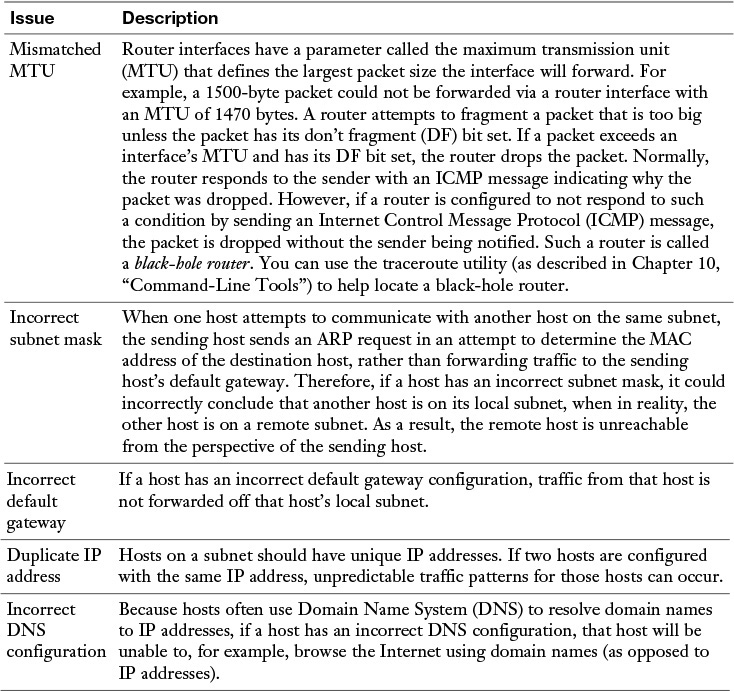
Table 13-4 Common Layer 3 Troubleshooting Issues
Network Layer Troubleshooting: Scenario
A common network layer troubleshooting issue, as described in Chapter 5, “IPv4 and IPv6 Addresses,” is a host with an IP address that is not valid for the subnet to which the host is physically connected. Using your subnetting skills, determine which host (client A or server 1) in Figure 13-6 is assigned an incorrect IP address, assuming the router interface’s IP address is correct.
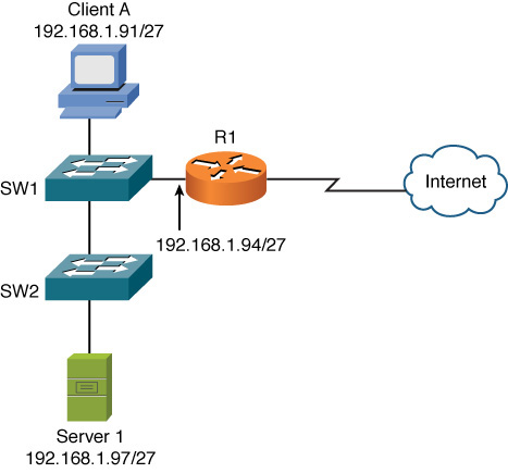
Figure 13-6 Data Link Layer Troubleshooting: Sample Topology
Network Layer Troubleshooting: Solution
The network shown in Figure 13-6 has subnetted the 192.168.1.0/24 network using a 27-bit subnet mask (255.255.255.224). To determine which client PC is assigned an IP address outside of its local VLAN, you need to determine the subnets created by the 27-bit subnet mask applied to the 192.168.1.0/24 network:
Step 1. The interesting octet for a 27-bit subnet mask is the fourth one because it is the last octet to contain a 1 in the 27-bit subnet mask (11111111.11111111.11111111.11100000, which could alternately be written as 255.255.255.224).
Step 2. The decimal value of the third octet in the subnet mask is 224. Therefore, the block size is 32 (256 – 224 = 32).
Step 3. The first 192.168.1.0/27 subnet is 192.168.1.0/27 (192.168.1.0/27 with the 3 borrowed bits in the third octet set to 0).
Step 4. Beginning with the first subnet of 192.168.1.0/27 and counting by the block size of 32 in the interesting octet yields the following subnets:
192.168.1.0/27
192.168.1.32/27
192.168.1.64/27
192.168.1.96/27
192.168.1.128/27
192.168.1.160/27
192.168.1.192/27
192.168.1.224/27
Based on the IP address of the router interface (192.168.1.94/27) and the previous list of subnets, you can determine that the router’s interface is in the 192.168.1.64/27 subnet. Similarly, you can determine the subnet of client A to be 192.168.1.64/27, and the subnet of server 1 to be 192.168.1.96/27. As a result, you can conclude that the host with an incorrect IP address is server 1 because its IP address is in a different subnet than the router interface’s subnet.
Network layer-related issues could also include duplicate IPs, speed and duplex mismatch, routing loops, incorrect IP, incorrect default gateway, network interface card (NIC) hardware failure, misconfigured Dynamic Host Configuration Protocol (DHCP), misconfigured DNS, incorrect cable or port, incomplete routing tables, NIC misconfiguration, or malware that is running on the computer preventing normal network behavior by the computer. Many of these issues can be verified using the tools and commands previously discussed in this book. In a production network, you would isolate the fault by testing individual components and then correct the problem once it is identified.
If performance or access is limited, it may also be due to a technical control that is in place on the network. Be sure to consider filters, traffic shaping, and firewalls that are in your control as part of the troubleshooting that is being done.
Wireless Troubleshooting
Troubleshooting wireless networks can require a variety of skill sets. For example, some troubleshooting scenarios might require an understanding of antenna theory and the radio frequency spectrum. However, the Network+ exam focuses on more common wireless issues, as presented in Table 13-5.
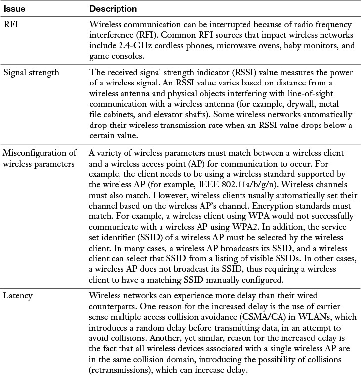
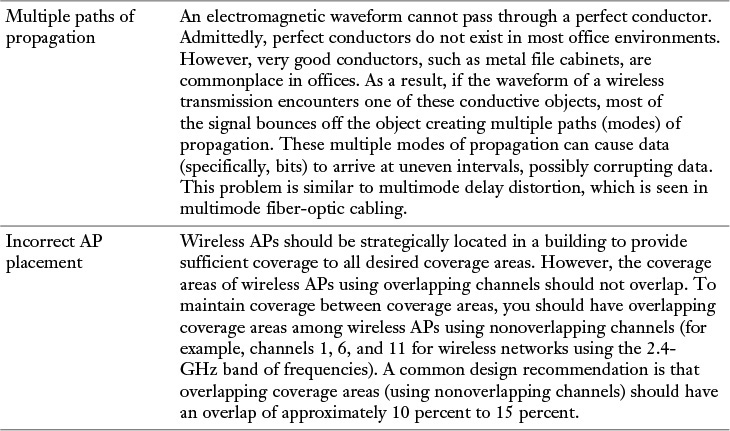
Table 13-5 Common Wireless Troubleshooting Issues *
Note
Chapter 8, “Wireless LANs,” discusses wireless networks in detail.
Wireless Network Troubleshooting: Scenario
As a practice troubleshooting scenario for wireless networks, consider Figure 13-7. Based on the topology provided, can you spot a design issue with the wireless network?
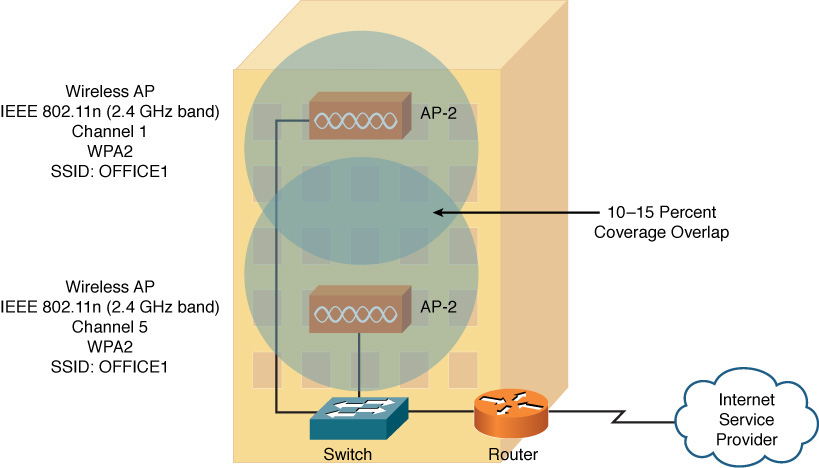
Figure 13-7 Wireless Network Troubleshooting: Sample Topology
Wireless Network Troubleshooting: Solution
The wireless network presented in Figure 13-7 has two wireless APs. Although these wireless APs have a matching wireless standard, encryption type, and SSID, the channels being used (channels 1 and 5) interfere with one another. Recall from Chapter 8 that channels in the 2.4-GHz band need at least five channels of separation (for overlapping coverage areas), whereas the channels used in this example only have four channels of separation. A fix for this issue is to assign AP-2 to channel 6, thus providing five channels of separation between AP-1 and AP-2.
A wireless analyzer may be needed to identify problems such as signal loss, overlapping or mismatched channels, unacceptable signal to noise ratios, rogue APs, and power levels. Breaking down a problem into smaller pieces allows you to identify the fault domain or the area that is causing the problem. For example, if a user cannot access the wireless network, the pieces involved may be the user connecting to an incorrect SSID or problems existing with the AP, the switch, the WLC, the RADIUS server, the AD server, or the user account and password itself. By testing the individual components where possible, you can isolate and then correct the problem.
Specialized Networks
In special-purpose networks, it may take some time to become familiar with the devices on that network. For example, a supervisory control and data acquisition (SCADA) network is used for the control of remote equipment and to monitor that equipment. This may be part of an industrial control system (ICS) that is used to manage a power plant or water treatment facility. Networks like these with distributed control systems (DCS) may have devices such as programmable logic controllers (PLC) and remote terminal units that are proprietary and may take specialized training to learn and troubleshoot.
In other specialized networks, such as those built for multimedia, video teleconference (VTC) and Voice over IP (VoIP), issues such as latency, jitter, and delay may cause applications to fail, and in that case quality of service (QoS) may need to be part of the troubleshooting process as well.
Some networks are purpose built for the communications between a server and its disk storage. IP Small Computer System Interface (iSCSI), Fibre Channel, and Network File System (NFS) are examples of network-attached storage (NAS).
Each network may have special requirements, and as you work with a specialized network and have hands-on experience with that network and its requirements, your ability to troubleshoot will increase, and the fundamentals of troubleshooting can be applied to these specialized networks.
Real-World Case Study
Bob is an employee at Acme Inc.. He is on a company-issued laptop that is connected wirelessly to the corporate HQ network. He is having a problem accessing a server that is located at one of the remote branch offices.
Because Bob is able to access the Internet and other local servers at the headquarters site, we can rule out issues with the local wireless or authentication because he is currently logged in.
Upon further investigation, it is discovered that Bob cannot ping the IP address of the remote server he is trying to reach. With additional testing, it is also determined that Bob cannot ping the IP address of the router at the remote branch office.
The routing table on the local HQ router is looked at, and the route to the remote site is in the routing table, but the local router cannot ping the remote router’s IP address. After contacting the primary service provider for the WAN connectivity, Acme learned that the provider was having an outage that was causing the problem with the connectivity over the provider’s MPLS network.
Acme’s fault-tolerant scenario should have triggered a VPN to be created using the Internet over the alternate service provider because of MPLS WAN connectivity failing.
Acme is going to change its router configuration to actively monitor the remote branch office routers so that in the future if there is a failure on the primary network, the VPN over the Internet to those branch offices will kick in to provide the fault-tolerant connectivity they are supposed to have.
Summary
The main topics covered in this chapter are the following:
![]() Troubleshooting concepts were discussed. In addition, you were presented with a structured troubleshooting methodology.
Troubleshooting concepts were discussed. In addition, you were presented with a structured troubleshooting methodology.
![]() Common physical layer troubleshooting issues were identified, and you tested your troubleshooting skills with a Layer 1 troubleshooting exercise.
Common physical layer troubleshooting issues were identified, and you tested your troubleshooting skills with a Layer 1 troubleshooting exercise.
![]() Data link layer troubleshooting was discussed, along with a collection of common issues (for example, VLANs, port configuration, and Layer 2 loops). Again, you were challenged with another troubleshooting scenario.
Data link layer troubleshooting was discussed, along with a collection of common issues (for example, VLANs, port configuration, and Layer 2 loops). Again, you were challenged with another troubleshooting scenario.
![]() Without dealing with the unique details of individual routing protocols, this chapter overviewed network layer troubleshooting, along with a list of the common Layer 3 issues. Then, based on the subnetting skills you learned in Chapter 6, you determined the host in a given topology that had an incorrect IP address assignment.
Without dealing with the unique details of individual routing protocols, this chapter overviewed network layer troubleshooting, along with a list of the common Layer 3 issues. Then, based on the subnetting skills you learned in Chapter 6, you determined the host in a given topology that had an incorrect IP address assignment.
![]() You reviewed common troubleshooting issues with wireless networks, including the need for wireless clients and wireless APs to have matching parameters, such as channel, encryption type, SSID, and wireless standard. Then you examined a wireless network design and identified a design flaw.
You reviewed common troubleshooting issues with wireless networks, including the need for wireless clients and wireless APs to have matching parameters, such as channel, encryption type, SSID, and wireless standard. Then you examined a wireless network design and identified a design flaw.
Exam Preparation Tasks
Review All the Key Topics
Review the most important topics from inside the chapter, noted with the Key Topic icon in the outer margin of the page. Table 13-6 lists these key topics and the page numbers where each is found.
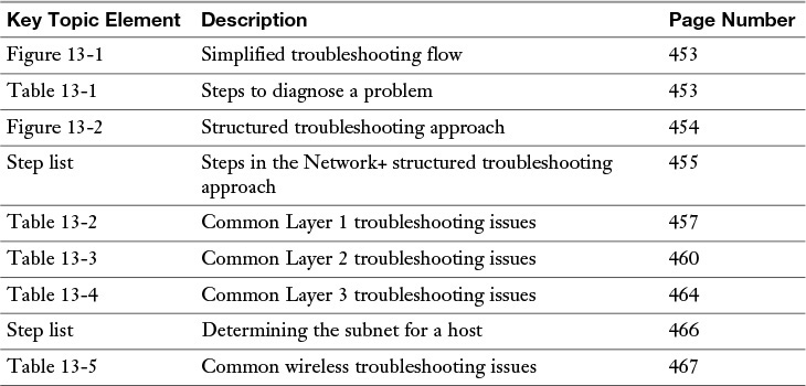
Table 13-6 Key Topics for Chapter 13
Complete Tables and Lists from Memory
Print a copy of Appendix D, “Memory Tables” (found on the DVD), or at least the section for this chapter, and complete the tables and lists from memory. Appendix E, “Memory Table Answer Key,” also on the DVD, includes the completed tables and lists so you can check your work.
Define Key Terms
Define the following key terms from this chapter, and check your answers in the Glossary:
trouble ticket
open
short
decibel loss
maximum transmission unit (MTU)
black-hole router
Complete Chapter 13 Hands-On Lab in Network+ Simulator Lite
![]() Troubleshooting Practice
Troubleshooting Practice
Review Questions
The answers to these review questions are in Appendix A, “Answers to Review Questions.”
1. Which of the following is most likely the first step in a structured troubleshooting methodology?
a. Hypothesize the probable cause.
b. Create an action plan.
c. Create a post-mortem report.
d. Define the problem.
2. Which of the following comprise a simplified troubleshooting flow? (Choose three.)
a. Problem resolution
b. Problem monitoring
c. Problem diagnosis
d. Problem report
3. A broken copper strand in a circuit is known as which of the following?
a. Short
b. Impedance
c. Open
d. Split pair
4. What Ethernet switch feature allows a port to automatically determine which of its leads are used for transmitting data and which of its leads are used for receiving data?
a. MDIX
b. STP
c. LAPD
d. UTP
5. In the absence of STP, what issues might result from a Layer 2 loop in a network? (Choose two.)
a. A router interface’s MTU decrementing
b. MAC address table corruption
c. Broadcast storms
d. Packet fragmentation
6. If you successfully ping from host A to host B, what can you conclude about host A?
a. Its OSI Layers 1–4 are functional.
b. Its OSI Layers 1–3 are functional.
c. Its OSI Layers 1–7 are functional.
d. You can only conclude that ICMP traffic can reach host B.
7. A router that drops a packet exceeding a router interface’s MTU size, when that packet has its “don’t fragment” bit set, is called which of the following?
a. Route reflector
b. Null hop
c. Zero-point router
d. Black-hole router
8. To what subnet does a host with an IP address of 172.16.155.10/18 belong?
a. 172.16.0.0 /18
b. 172.16.96.0 /18
c. 172.16.128.0 /18
d. 172.16.154.0 /18
9. Which of the following is a value measuring the power of a wireless signal?
a. RSSI
b. SSID
c. RFI
d. CSMA/CA
10. Which of the following are common sources of wireless network radio frequency interference (RFI)? (Choose three.)
a. Game consoles
b. 900-MHz cordless phones
c. Microwave ovens
d. Baby monitors
All materials on the site are licensed Creative Commons Attribution-Sharealike 3.0 Unported CC BY-SA 3.0 & GNU Free Documentation License (GFDL)
If you are the copyright holder of any material contained on our site and intend to remove it, please contact our site administrator for approval.
© 2016-2026 All site design rights belong to S.Y.A.