CompTIA Network+ N10-006 Cert Guide (2015)
Chapter 5. IPv4 and IPv6 Addresses
After completion of this chapter, you will be able to answer the following questions:
![]() How are decimal numbers represented in binary format?
How are decimal numbers represented in binary format?
![]() What is the format of an IP Version 4 (IPv4) address, and what are the distinctions between unicast, broadcast, and multicast addresses?
What is the format of an IP Version 4 (IPv4) address, and what are the distinctions between unicast, broadcast, and multicast addresses?
![]() Which options are available for assigning IP addresses to networked devices?
Which options are available for assigning IP addresses to networked devices?
![]() Given a subnet design requirement (for example, a number of required subnets and a number of required hosts per subnet), how do you determine the appropriate subnet mask for a network?
Given a subnet design requirement (for example, a number of required subnets and a number of required hosts per subnet), how do you determine the appropriate subnet mask for a network?
![]() What are the primary characteristics of IPv6?
What are the primary characteristics of IPv6?
When two devices on a network want to communicate, they need logical addresses (that is, Layer 3 addresses as described in Chapter 2, “The OSI Reference Model”). Most modern networks use Internet Protocol (IP) addressing, as opposed to other Layer 3 addressing schemes (for example, Apple’s AppleTalk or Novell’s Internetwork Packet Exchange [IPX]). Therefore, the focus of this chapter is IP.
Two versions of IP are addressed. First, this chapter discusses how IP concepts apply to IP Version 4 (IPv4). This discussion introduces you to how IP addresses are represented in binary notation. You examine the structure of an IPv4 address and distinguish between different categories of IPv4 addresses.
Next, various options for assigning IP addresses to end stations are contrasted. Also, one of the benefits of IP addressing is that you have flexibility in how you can take a network address and subdivide that address into multiple subnets. This discussion of subnetting tends to get a bit mathematical. So you are provided with multiple practice exercises to help solidify these concepts in your mind.
Although IPv4 is the most widely deployed Layer 3 addressing scheme in today’s networks, its scalability limitation is causing available IPv4 addresses to quickly become depleted. Fortunately, a newer version of IP, IP Version 6 (IPv6), is scalable beyond anything we will need in our lifetimes. So, after focusing on the foundation of IP addressing laid by IPv4, this chapter concludes by introducing you to the fundamental characteristics of IPv6 addressing.
Foundation Topics
Binary Numbering
Chapter 2 described how a network transmitted data as a series of binary 1s and 0s. Similarly, IP addresses can be represented as a series of binary digits (that is, bits). IPv4 consists of 32 bits, and IPv6 contains a whopping 128 bits.
Later in this chapter, you need to be able to convert between the decimal representation of a number and that number’s binary equivalent. This skill is needed for things such as subnet mask calculations. This section describes this mathematical procedure and provides you with practice exercises.
Principles of Binary Numbering
We’re accustomed to using Base-10 numbering in our daily lives. In a Base-10 numbering system, there are ten digits, in the range of 0 through 9, at our disposal. Binary numbering, however, uses a Base-2 numbering system, where there are only two digits: zero (0) and one (1).
Because 32-bit IPv4 addresses are divided into four 8-bit octets, this discussion focuses on converting between 8-bit binary numbers and decimal numbers. To convert a binary number to decimal, you can create a table similar to Table 5-1.


Table 5-1 Binary Conversion Table
Note the structure of the table. There are eight columns, representing the 8 bits in an octet. The column headings are the powers of 2 (the powers of 0–7), beginning with the rightmost column. Specifically, 2 raised to the power of 0 (20) is 1. (In fact, any number raised to the 0 power is 1.) If you raise a 2 to the first power (21), that equals 2. A 2 raised to the second power (that is, 2 * 2, or 22) is 4. This continues through 2 raised to the power of 7 (that is, 2 * 2 * 2 * 2 * 2 * 2 * 2, or 27), which equals 128. This table can be used for converting binary numbers to decimal and decimal numbers to binary. The skill of binary-to-decimal and decimal-to-binary conversion is critical for working with subnet masks, as discussed later in this chapter.
Converting a Binary Number to a Decimal Number
To convert a binary number to a decimal number, you populate the previously described binary table with the given binary digits. Then you add up the column heading values for those columns containing a 1.
For example, consider Table 5-2. Only the 128, 16, 4, and 2 columns contain a 1, and all the other columns contain a 0. If you add all the column headings containing a 1 in their column (that is, 128 + 16 + 4 + 2), you get a result of 150. Therefore, you can conclude that the binary number of 10010110 equates to a decimal value of 150.

Table 5-2 Binary Conversion Example 1
Converting a Decimal Number to a Binary Number
To convert numbers from decimal to binary, staring with the leftmost column, ask the question, “Is this number equal to or greater than the column heading?” If the answer to that question is no, place a 0 in that column and move to the next column. If the answer is yes, place a 1 in that column and subtract the value of the column heading from the number you are converting. When you then move to the next column (to your right), again ask yourself, “Is this number (which is the result of your previous subtraction) equal to or greater than the column heading?” This process continues (to the right) for all the remaining column headings.
For example, imagine that you want to convert the number 167 to binary. The following steps walk you through the process:
Step 1. Ask the question, “Is 167 equal to or greater than 128?” Because the answer is yes, you place a 1 in the 128 column, as shown in Table 5-3 and subtract 128 from 167, which yields a result of 39.

Table 5-3 Binary Conversion Example 2: Step 1
Step 2. Now that you are done with the 128 column, move (to the right) to the 64 column. Ask the question, “Is 39 equal to or greater than 64?” Because the answer is no, you place a 0 in the 64 column, as shown in Table 5-4, and continue to the next column (the 32 column).

Table 5-4 Binary Conversion Example 2: Step 2
Step 3. Under the 32 column, ask the question, “Is 39 equal to or greater than 32?” Because the answer is yes, you place a 1 in the 32 column, as shown in Table 5-5, and subtract 32 from 39, which yields a result of 7.

Table 5-5 Binary Conversion Example 2: Step 3
Step 4. Now you are under the 16 column and ask, “Is 7 equal to or greater than 16?” Because the answer is no, you place a 0 in the 16 column, as shown in Table 5-6, and move to the 8 column.

Table 5-6 Binary Conversion Example 2: Step 4
Step 5. Similar to the 16 column, the number 7 is not equal to or greater than an 8. So, a 0 is placed in the 8 column, as shown in Table 5-7.

Table 5-7 Binary Conversion Example 2: Step 5
Step 6. Because 7 is greater than or equal to 4, a 1 is placed in the 4 column, as shown in Table 5-8, and 4 is subtracted from 7, yielding 3 as the result.

Table 5-8 Binary Conversion Example 2: Step 6
Step 7. Now under the 2 column, you ask the question, “Is 3 greater than or equal to 2?” Because the answer is yes, you place a 1 in the 2 column, as shown in Table 5-9, and subtract 2 from 3.

Table 5-9 Binary Conversion Example 2: Step 7
Step 8. Finally, in the rightmost column (that is, the 1 column), you ask whether the number 1 is greater than or equal to 1. Because it is, you place a 1 in the 1 column, as shown in Table 5-10.

Table 5-10 Binary Conversion Example 2: Step 8
You can now conclude that a decimal number of 167 equates to a binary value of 10100111. In fact, you can check your work by adding up the values for the column headings that contain a 1 in their column. In this example, the 128, 32, 4, 2, and 1 columns contain a 1. If you add these values, the result is 167 (that is, 128 + 32 + 4 + 2 + 1 = 167).
Binary Numbering Practice
Because binary number conversion is a skill developed through practice, you are now challenged with a few conversion exercises. The first two exercises ask you to convert a binary number to a decimal number, and the last two exercises ask you to convert a decimal number to a binary number.
Binary Conversion Exercise 1
Using Table 5-11 as a reference, convert the number binary number 01101011 to a decimal number.

Table 5-11 Binary Conversion Exercise 1: Base Table
Write your answer here: ___________
Binary Conversion Exercise 1: Solution
Given a binary number of 01101011 and filling in a binary conversion table, as shown in Table 5-12, we notice that the 64, 32, 8, 2, and 1 columns contain a 1. Each of the other columns contains a 0. By adding up the value of these column headings (that is, 64 + 32 + 8 + 2 + 1), you get a decimal value of 107.

Table 5-12 Binary Conversion Exercise 1: Solution Table
Binary Conversion Exercise 2
Using Table 5-13 as a reference, convert the number binary number 10010100 to a decimal number.

Table 5-13 Binary Conversion Exercise 2: Base Table
Write your answer here: ___________
Binary Conversion Exercise 2: Solution
Given a binary number of 10010100 and filling in a binary conversion table, as shown in Table 5-14, we notice that the 128, 16, and 4 columns contain a 1. Each of the other columns contains a 0. By adding up the value of these column headings (that is, 128 + 16 + 4), you get a decimal value of 148.

Table 5-14 Binary Conversion Exercise 2: Solution Table
Binary Conversion Exercise 3
Using Table 5-15 as a reference, convert the number decimal number 49 to a binary number.

Table 5-15 Binary Conversion Exercise 3: Base Table
Write your answer here: ___________
Binary Conversion Exercise 3: Solution
You can begin your conversion of the decimal number 49 to a binary number by asking the following questions and performing the following calculations:
1. Is 49 greater than or equal to 128? => No => Put a 0 in the 128 column.
2. Is 49 greater than or equal to 64? => No => Put a 0 in the 64 column.
3. Is 49 greater than or equal to 32? => Yes => Put a 1 in the 32 column, and subtract 32 from 49. => 49 – 32 = 17.
4. Is 17 greater than or equal to 16? => Yes => Put a 1 in the 16 column, and subtract 16 from 17. => 17 – 16 = 1.
5. Is 1 greater than or equal to 8? => No => Put a 0 in the 8 column.
6. Is 1 greater than or equal to 4? => No => Put a 0 in the 4 column.
7. Is 1 greater than or equal to 2? => No => Put a 0 in the 2 column.
8. Is 1 greater than or equal to 1? => Yes => Put a 1 in the 1 column.
Combining these eight binary digits forms a binary number of 00110001, as shown in Table 5-16. Verify your work by adding the values of the column headings whose columns contain a 1. In this case, columns 32, 16, and 1 each have a 1 in their column. By adding these values (that is, 32 + 16 + 1), you get a value of 49.

Table 5-16 Binary Conversion Exercise 3: Solution Table
Binary Conversion Exercise 4
Using Table 5-17 as a reference, convert the number decimal number 236 to a binary number.

Table 5-17 Binary Conversion Exercise 4: Base Table
Write your answer here: ___________
Binary Conversion Exercise 4: Solution
You can begin your conversion of the decimal number 236 to a binary number by asking the following questions and performing the following calculations:
1. Is 236 greater than or equal to 128? => Yes => Put a 1 in the 128 column, and subtract 128 from 236. => 236 – 128 = 108.
2. Is 108 greater than or equal to 64? => Yes => Put a 1 in the 64 column, and subtract 64 from 108. => 108 – 64 = 44.
3. Is 44 greater than or equal to 32? => Yes => Put a 1 in the 32 column, and subtract 32 from 44. => 44 – 32 = 12.
4. Is 12 greater than or equal to 16? => No => Put a 0 in the 16 column.
5. Is 12 greater than or equal to 8? => Yes => Put a 1 in the 8 column, and subtract 8 from 12. => 12 – 8 = 4.
6. Is 4 greater than or equal to 4? => Yes => Put a 1 in the 4 column, and subtract 4 from 4. 4 – 4 = 0.
7. Is 0 greater than or equal to 2? => No => Put a 0 in the 2 column.
8. Is 0 greater than or equal to 1? => No => Put a 0 in the 1 column.
Combining these eight binary digits forms a binary number of 11101100, as shown in Table 5-18. You can verify your work by adding the values of the column headings whose columns contain a 1. In this case, columns 128, 64, 32, 8, and 4 each have a 1 in their column. By adding these values (that is, 128 + 64 + 32 + 8 + 4), you get a value of 236.

Table 5-18 Binary Conversion Exercise 4: Solution Table
IPv4 Addressing
Although IPv6 is increasingly being adopted in corporate networks, IPv4 is by far the most popular Layer 3 addressing scheme in today’s networks. For brevity in this section, the term IPv4 address will be used interchangeably with the more generic term IP address.
Devices on an IPv4 network use unique IP addresses to communicate with one another. Metaphorically, you can relate this to sending a letter through the postal service. You place a destination address on an envelope containing the letter, and in the upper-left corner of the envelope, you place your return address. Similarly, when an IPv4 network device sends data on a network, it places both a destination IP address and a source IP address in the packet’s IPv4 header.
IPv4 Address Structure
An IPv4 address is a 32-bit address. However, rather than writing out each individual bit value, the address is typically written in dotted-decimal notation. Consider the IP address of 10.1.2.3. This address is written in dotted-decimal notation. Notice that the IP address is divided into four separate numbers, separated by periods. Each number represents one-fourth of the IP address. Specifically, each number represents an 8-bit portion of the 32 bits in the address. Because each of these four divisions of an IP address represent 8 bits, these divisions are called octets. For example, Figure 5-1 shows the binary representation of the 10.1.2.3 IP address. In Figure 5-1, notice that the eight leftmost bits of 00001010 equate to a decimal value of 10 (the calculation for which was described in the previous section). Similarly, 00000001 in binary equates to a 1 in decimal. A 00000010 in binary equals 2 in decimal, and finally, 00000011 yields a decimal value of 3.
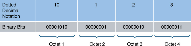
Figure 5-1 Binary Representation of Dotted-Decimal IP Address
Interestingly, an IP address is composed of two types of addresses: a network address and a host address. Specifically, a group of contiguous left-justified bits represent the network address, and the remaining bits (that is, a group of contiguous right-justified bits) represent the address of a host on a network. The IP address component that determines which bits refer to the network and which bits refer to the host is called the subnet mask. You can think of the subnet mask as a dividing line separating an IP address’s 32 bits into a group of network bits (on the left) and a group of host bits (on the right).
A subnet mask typically consists of a series of contiguous 1s followed by a set of continuous 0s. In total, a subnet mask contains 32 bits, which correspond to the 32 bits found in an IPv4 address. The 1s in a subnet mask correspond to network bits in an IPv4 address, and 0s in a subnet mask correspond to host bits in an IPv4 address.
For example, consider Figure 5-2. The eight leftmost bits of the subnet mask are 1s, and the remaining 24 bits are 0s. As a result, the 8 leftmost bits of the IP address represent the network address, and the remaining 24 bits represent the host address.
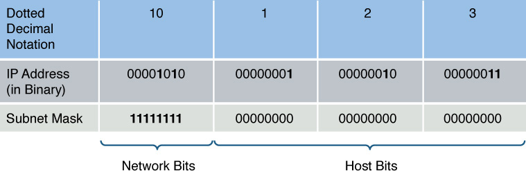
Figure 5-2 Dividing an IP Address into a Network Portion and a Host Portion
When you write a network address, all host bits are set to 0s. Once again, consider the example shown in Figure 5-2. The subnet mask in this example is an 8-bit subnet mask, meaning that the 8 leftmost bits in the subnet mask are 1s. If the remaining bits were set to 0, as shown in Figure 5-3, the network address of 10.0.0.0 can be seen.
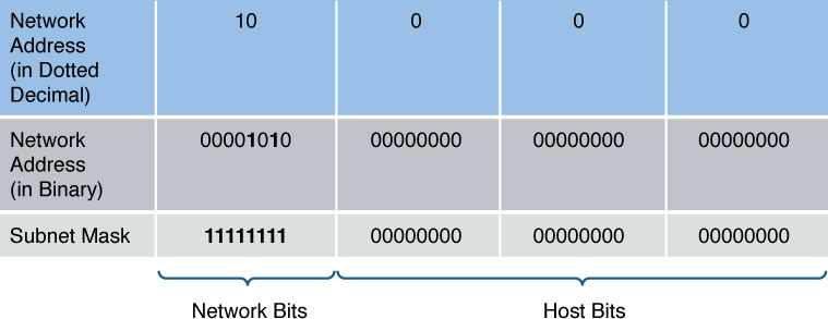
Figure 5-3 Network Address Calculation
When writing a network address, or an IP address for that matter, more detail needs to be provided than just a dotted-decimal representation of an IP address’s 32 bits. For example, just being told that a device has an IP address of 10.1.2.3 does not tell you the network on which the IP address resides. To know the network address, you need to know the subnet mask, which could be written in dotted-decimal notation or in prefix notation (also known as slash notation). In the example, where we have an IP address of 10.1.2.3 and an 8-bit subnet mask, the IP address could be written as 10.1.2.3 255.0.0.0 or 10.1.2.3 /8. Similarly, the network address could be written as 10.0.0.0 255.0.0.0 or 10.0.0.0 /8.
Classes of Addresses
Although an IP address (or a network address) needs subnet mask information to determine which bits represent the network portion of the address, there are default subnet masks with which you should be familiar. The default subnet mask for a given IP address is solely determined by the value in the IP address’s first octet. Table 5-19 shows the default subnet masks for various ranges of IP addresses.
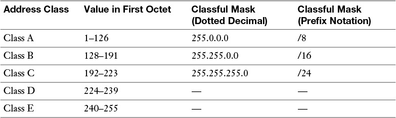
Table 5-19 IP Address Classes
These ranges of IP address, which you should memorize, are referred to as different classes of addresses. Classes A, B, and C are those ranges of addresses assigned to network devices. Class D addresses are used as destination IP addresses (that is, not assigned to devices sourcing traffic) for multicast networks, and Class E addresses are reserved for experimental use. The default subnet masks associated with address classes A, B, and C are called classful masks.
For example, consider an IP address of 172.16.40.56. If you were told that this IP address used its classful mask, you should know that it has a subnet mask of 255.255.0.0, which is the classful mask for a Class B IP address. You should know that 172.16.40.56 is a Class B IP address, based on the value of the first octet (172), which falls in the Class B range of 128–191.
Note
You might have noticed that in the ranges of values in the first octet, the number 127 seems to have been skipped. The reason is that 127 is used as a loopback IP address, meaning a locally significant IP address representing the device itself. For example, if you were working on a network device and wanted to verify that device had a TCP/IP stack loaded, you could attempt to ping an IP address of 127.1.1.1. If you received ping responses, you could conclude that the device is running a TCP/IP stack. The ping function is discussed in Chapter 10, “Command-Line Tools.”
Publicly routable IP addresses are globally managed by the Internet Corporation for Assigned Names and Numbers (ICANN) nonprofit corporation. ICANN does not directly assign a block of IP addresses to your Internet service provider (ISP), but assigns a block of IP addresses to a regional Internet registry. One example of a regional Internet registry is the American Registry for Internet Numbers (ARIN), which acts as an Internet registry for North America.
The Internet Assigned Numbers Authority (IANA) is yet another entity responsible for IP address assignment. IANA is operated by ICANN and is responsible for IP address assignment outside of North America.
Note
Some literature might make reference to the Internet Network Information Center (InterNIC). InterNIC was the predecessor to ICANN (until September 18, 1998).
When an organization is assigned one or more publicly routable IP addresses by its service provider, that organization often needs more IP addresses to accommodate all of its devices. One solution is to use private IP addressing within an organization, in combination with Network Address Translation (NAT). Specific Class A, B, and C networks have been designed for private use. Although these networks are routable (with the exception of the 169.254.0.0–169.254.255.255 address range), within the organization, ISPs do not route these private networks over the public Internet. Table 5-20 shows these IP networks reserved for internal use.
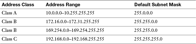
Table 5-20 Private IP Networks
Note
The 169.254.0.0–169.254.255.255 address range is not routable. Addresses in the range are only usable on their local subnet and are dynamically assigned to network hosts using the Automatic Private IP Addressing (APIPA) feature, which is discussed later in this section.
NAT is a feature available on routers that allows private IP addresses used within an organization to be translated into a pool of one or more publicly routable IP addresses. Chapter 6, “Routing IP Packets,” describes the operation of NAT.
Types of Addresses
For the real world and for the Network+ exam, you need to be familiar with the following three categories of IPv4 addresses: unicast, broadcast, and multicast. The following sections describe these in detail.
Unicast
Most network traffic is unicast in nature, meaning that traffic travels from a single source device to a single destination device. Figure 5-4 illustrates an example of a unicast transmission.
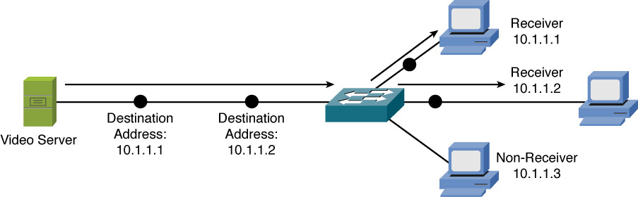
Figure 5-4 Sample Unicast Transmission
Broadcast
Broadcast traffic travels from a single source to all destinations on a network (that is, a broadcast domain). A broadcast address of 255.255.255.255 might seem that it would reach all hosts on all interconnected network. However, 255.255.255.255 targets all devices on a single network, specifically the network local to the device sending a packet destined for 255.255.255.255. Another type of broadcast address is a directed broadcast address, which targets all devices in a remote network. For example, the address 172.16.255.255 /16 is a directed broadcast targeting all devices in the 172.16.0.0 /16 network. Figure 5-5 illustrates an example of a broadcast transmission.
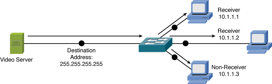
Figure 5-5 Sample Broadcast Transmission
Multicast
Multicast technology provides an efficient mechanism for a single host to send traffic to multiple, yet specific, destinations. For example, imagine a network with 100 users. Twenty of those users want to receive a video stream from a video server. With a unicast solution, the video server would have to send 20 individual streams, one stream for each recipient. Such a solution could consume a significant amount of network bandwidth and put a heavy processor burden on the video server.
With a broadcast solution, the video server would only have to send the video stream once; however, it would be received by every device on the local subnet, even devices not wanting to receive the video stream. Even though those devices do not want to receive the video stream, they still have to pause what they are doing and take time to check each of these unwanted packets.
As shown in Figure 5-6, multicast offers a compromise, allowing the video server to send the video stream only once, and only sending the video stream to devices on the network that wants to receive the stream. What makes this possible is the use of a Class D address. A Class D address, such as 239.1.2.3, represents the address of a multicast group. The video server could, in this example, send a single copy of each video stream packet destined for 239.1.2.3. Devices wanting to receive the video stream can join the multicast group. Based on the device request, switches and routers in the topology can then dynamically determine out of which ports the video stream should be forwarded.
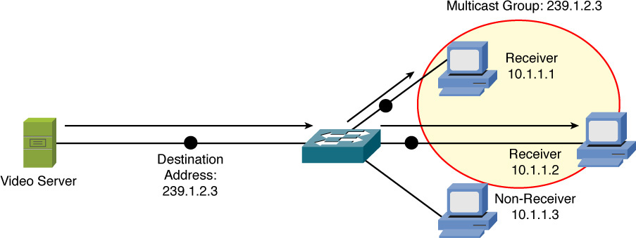
Figure 5-6 Sample Multicast Transmission
Assigning IPv4 Addresses
At this point in the discussion, you should understand that networked devices need an IP address. However, beyond just an IP address, what extra IP address-related information needs to be provided, and how does an IP address get assigned to one of those devices?
This section begins by discussing various parameters that might be assigned to a networked device, followed by discussions addressing various approaches to assign IP addresses to devices.
IP Addressing Components
As discussed in the previous section, an IP address has two portions: a network portion and a host portion. A subnet mask is required to delineate between these two portions.
In addition, if traffic is destined for a different subnet than the subnet on which the traffic originates, a default gateway needs to be defined. A default gateway routes traffic from the sender’s subnet toward the destination subnet. The concept of routing is addressed in Chapter 6.
Another consideration is that end users typically do not type in the IP address of the destination device with which they want to connect (for example, a web server on the Internet). Instead, end users typically type in fully qualified domain names (FQDN), such as www.1ExamAMonth.com. When connecting to devices on the public Internet, a Domain Name System (DNS) server takes an FQDN and translates it into a corresponding IP address.
In a company’s internal network (that is, an intranet), a Microsoft Windows Internet Name Service (WINS) server might be used, as an example, to convert the names of network devices into their corresponding IP addresses. For example, you might attempt to navigate to a shared folder of \\server1\hrdocs. A WINS server could then be used to resolve the network device name of server1 to a corresponding IP address. The path of \\server1\hrdocs is in universal naming convention (UNC) form, where you are specifying a network device name (for example, server1) and a resource available on that device (for example, hrdocs). More and more companies today are transitioning to DNS even for internal network name resolution.
To summarize, network devices (for example, an end-user PC) can benefit from a variety of IP address parameters, such as the following:
![]() IP address
IP address
![]() Subnet mask
Subnet mask
![]() Default gateway
Default gateway
![]() Server addresses
Server addresses
Static Configuration
A simple way of configuring a PC, for example, with IP address parameters is to statically configure that information. For example, on a PC running Microsoft Windows 7 or 8 as the operating system, you can navigate to the Control Panel, as shown in Figure 5-7, and click Network and Internet.
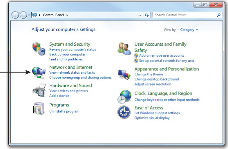
Figure 5-7 Windows Control Panel
From the Network and Internet control panel, click Network and Sharing Center, as shown in Figure 5-8.
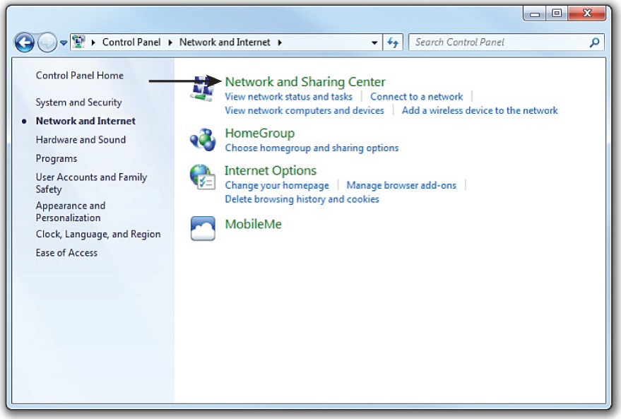
Figure 5-8 Network and Internet Control Panel
You can then click the Change adapter settings link, as shown in Figure 5-9.
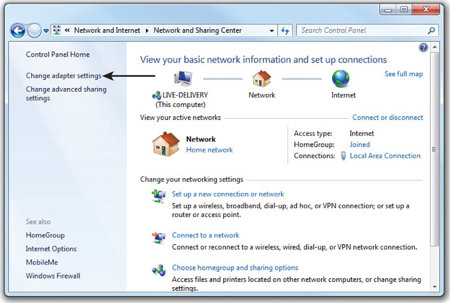
Figure 5-9 Network and Sharing Center
From the Network Connections window, double-click the network adapter whose settings you want to change, as shown in Figure 5-10.
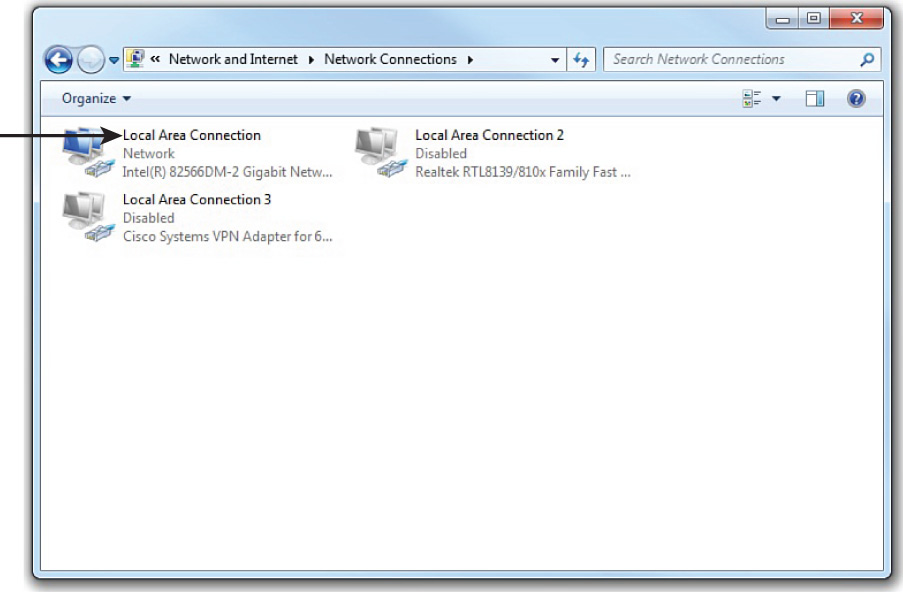
Figure 5-10 Network Connections Window
You are then taken to the Local Area Connection Status window, as shown in Figure 5-11. From here, you can click the Properties button.
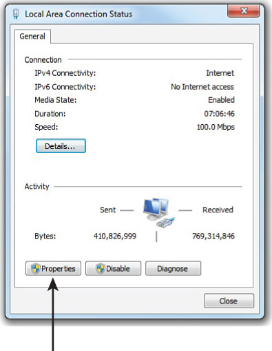
Figure 5-11 Local Area Connection Status Window
As shown in Figure 5-12, you can highlight Internet Protocol Version 4 (TCP/IPv4) and click the Properties button.
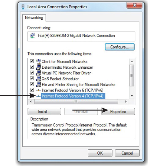
Figure 5-12 Local Area Connection Properties
An IP address, subnet mask, default gateway, and DNS server information can be entered into the Internet Protocol Version 4 (TCP/IPv4) Properties window, as depicted in Figure 5-13. Although DNS server information can be entered in this window, more advanced DNS options and WINS options are available by clicking the Advanced button.
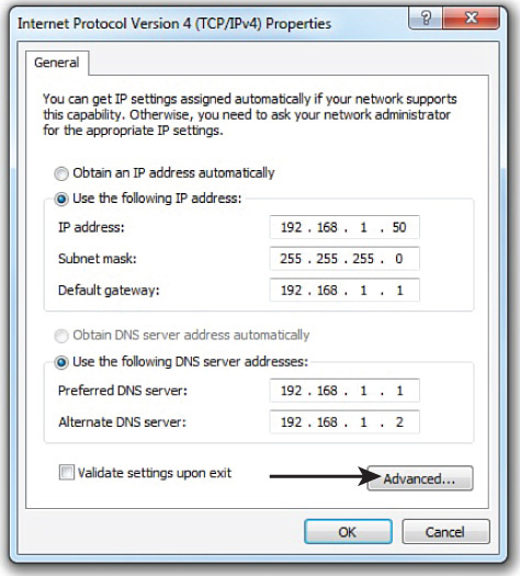
Figure 5-13 Internet Protocol Version 4 (TCP/IPv4) Properties
By clicking the DNS tab in the Advanced TCP/IP Settings, as shown in Figure 5-14, you can add, remove, or reorder DNS servers, in addition to adjusting various other DNS parameters. Recall that a DNS server converts an FQDN to an IP address. Also, although Figure 5-13 shows the same IP address for the default gateway and a DNS server, these are not always located on the same device.
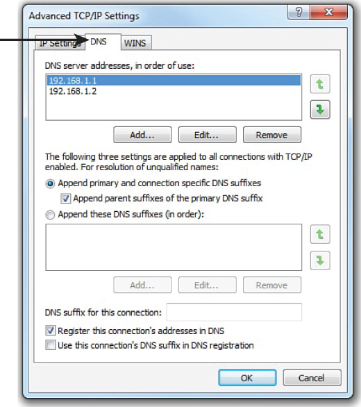
Figure 5-14 Advanced TCP/IP Settings: DNS Tab
Similarly, Windows Internet Name Service (WINS) servers can be configured in the WINS tab of the Advanced TCP/IP Settings window, as shown in Figure 5-15. Similar to a DNS server, a WINS server converts a NetBIOS computer name to a corresponding IP address.
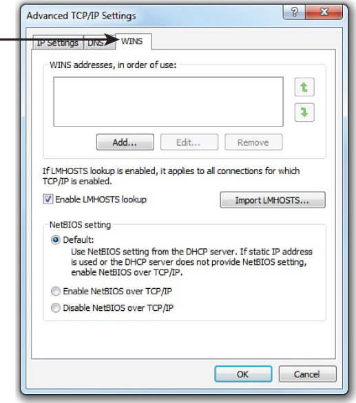
Figure 5-15 Advanced TCP/IP Settings: WINS Tab
Dynamic Configuration
Statically assigning IP address information to individual networked devices can be time consuming, error-prone, and lacking in scalability. Instead of static IP address assignments, many corporate networks dynamically assign IP address parameters to their devices. An early option for performing this automatic assignment of IP addresses was called Bootstrap Protocol (BOOTP for short). Currently, however, the most popular approach for dynamic IP address assignment is Dynamic Host Configuration Protocol (DHCP).
BOOTP
BOOTP was developed as a method of assigning IP address, subnet mask, and default gateway information to diskless workstations. In the early days of Microsoft Windows (for example, Microsoft Windows 3.1), Microsoft Windows did not natively support TCP/IP. To add TCP/IP support, an add-on TCP/IP application (for example, Trumpet Winsock) could be run. Such an application would typically support BOOTP.
When a device needed to obtain IP address information, a BOOTP broadcast would be sent out from the device needing an IP address. If a BOOTP server (BOOTPS) received the broadcast, it could match the source MAC address in the received frame (the MAC address from the device wanting to obtain an IP address) with a corresponding IP address, in a database stored on the BOOTP server. The BOOTPS would then respond to the requesting client with IP address information. Because BOOTP requests were based on broadcasts, by default, a BOOTP request could not propagate beyond a device’s local subnet. However, most enterprise-class routers can be configured to forward selected broadcast types, including BOOTP broadcasts.
DHCP
DHCP offers a more robust solution to IP address assignment than the solution offered by BOOTP. DHCP does not require a statically configured database of MAC address to IP address mappings. Also, DHCP has a wide variety of options beyond basic IP address, subnet mask, and default gateway parameters. For example, a DHCP server can educate a DHCP client about the IP address of a WINS server, or even an administrator-defined parameter (for example, the IP address of a TFTP server from which a configuration file could be downloaded).
Refer to Chapter 3, “Network Components,” for more information about the operation of DHCP. However, realize that, like BOOTP, DHCP’s initial request is a broadcast, requiring a client’s local router be configured to appropriately forward DHCP requests to a DHCP server if that DHCP server is not on the local subnet of the requesting client.
In setting up a DHCP server, you would identify a range of IP addresses to hand out, and this would be referred to as the scope. In addition, a DHCP server can be configured to have reservations, which will assign a specific IP address to a specific Layer 2 Ethernet MAC address. The lease time can also be configured and is usually set to one day. The DHCP server can also provide options such as DNS server addresses, the default gateway to use, domain suffixes to use, and more. If a DHCP client is not on the same subnet as a DHCP server, a router or other device that is connected to the same subnet as the DHCP client can be configured as a DHCP relay and can take the discover packet from the client and route it to where the DHCP server is. This feature is also sometimes referred to as IP helper.
As an example of DHCP client configuration, in Microsoft Windows 7, you can select the Obtain an IP address automatically and Obtain DNS server address automatically options in the Internet Protocol Version 4 (TCP/IPv4) Properties window, as shown in Figure 5-16.
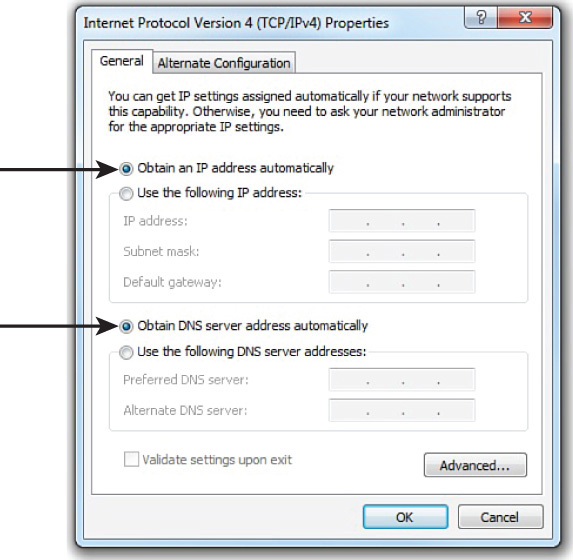
Figure 5-16 Configuring Microsoft Windows 7 to Obtain IP Address Information via DHCP
Note
A protocol rendered obsolete by BOOTP and DHCP is Reverse Address Resolution Protocol (RARP). Although Address Resolution Protocol (ARP) requests a MAC address that corresponds to a known IP address, RARP requested an IP address (from a preconfigured host) that corresponded to a station’s MAC address. Although RARP did allow a station to dynamically obtain an IP address, both BOOTP and DHCP offer additional features.
Automatic Private IP Addressing
If a networked device does not have a statically configured IP address and is unable to contact a DHCP server, it still might be able to communicate on an IP network thanks to Automatic Private IP Addressing (APIPA). The APIPA feature allows a networked device to self-assign an IP address from the 169.254.0.0/16 network. Note that this address is usable only on the device’s local subnet. (The IP address is not routable.)
As shown in Figure 5-17, Microsoft Windows 7 defaults to APIPA if a client is configured to automatically obtain IP address information and that client fails to obtain IP address information from a DHCP server.
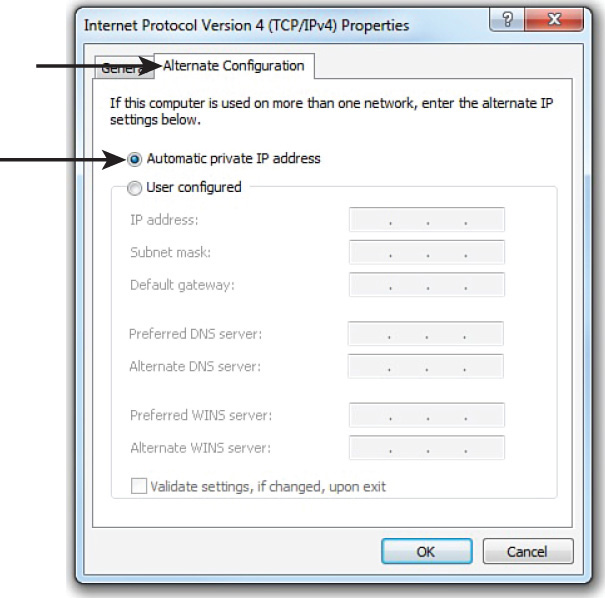
Figure 5-17 APIPA Configuration Enabled by Default
APIPA was designed as a solution for quickly setting up a localized network without the need to configure a DHCP server or the need to statically assign IP address information. However, there remains a need for devices on this localized network to perform name resolution and discover network services. Fortunately, these needs are addressed by Zero Configuration (Zeroconf). Zeroconf is a technology supported on most modern operating systems and performs three basic functions:
![]() Assigning link-local IP addresses: A link-local IP address is a nonroutable IP address usable only on a local subnet. APIPA is an example of a technology that assigns link-local IP addresses.
Assigning link-local IP addresses: A link-local IP address is a nonroutable IP address usable only on a local subnet. APIPA is an example of a technology that assigns link-local IP addresses.
![]() Resolving computer names to IP addresses: Multicast Domain Name Service (mDNS) is an example of a technology that can resolve computer names to their corresponding IP address on a local subnet, without the aid of a DNS server or a WINS server.
Resolving computer names to IP addresses: Multicast Domain Name Service (mDNS) is an example of a technology that can resolve computer names to their corresponding IP address on a local subnet, without the aid of a DNS server or a WINS server.
![]() Locating network services: Examples of service discovery protocols include the standards-based Service Location Protocol (SLP), Microsoft’s Simple Service Discovery Protocol (SSDP), and Apple’s DNS-based Service Discovery (DNS-SD).
Locating network services: Examples of service discovery protocols include the standards-based Service Location Protocol (SLP), Microsoft’s Simple Service Discovery Protocol (SSDP), and Apple’s DNS-based Service Discovery (DNS-SD).
If devices supporting these three Zeroconf features are interconnected on a local subnet, they can dynamically obtain link-local IP addresses, resolve one another’s names to IP addresses, and discover services available on a network.
Subnetting
Earlier in this chapter, you were introduced to the purpose of a subnet mask and the default subnet masks for the various IP addresses classes. Default subnet masks (that is, classful subnet masks) are not always the most efficient choice. Fortunately, you can add additional network bits to a subnet mask (thereby extending the subnet mask) to create subnets within a classful network. This section explains why you might want to perform this process and describes how you mathematically perform subnet calculations.
Purpose of Subnetting
Consider the number of assignable IP addresses in the various classes of IP addresses shown in Table 5-21. Recall that the host bits of an IP address cannot be all 0s (which represents the network address) or all 1s (which represents the directed broadcast address). Therefore, the number of assignable IP addresses in a subnet can be determined by the following formula:
Number of assignable IP addresses in a subnet = 2h – 2,
where h is the number of host bits in a subnet mask
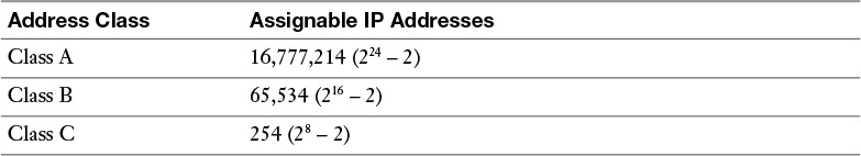
Table 5-21 Assignable IP Addresses
Suppose that you decide to use a private Class B IP address (for example, 172.16.0.0/16) for your internal IP addressing. For performance reasons, you probably would not want to support as many as 65,534 hosts in a single broadcast domain. Therefore, a best practice is to take such a network address and subnet the network (thereby extending the number of network bits in the network’s subnet mask) into additional subnetworks.
Subnet Mask Notation
As previously mentioned, the number of bits in a subnet mask can be represented in dotted-decimal notation (for example, 255.255.255.0) or in prefix notation (for example, /24). As a reference, Table 5-22 shows valid subnet masks in dotted-decimal notation and the corresponding prefix notation.
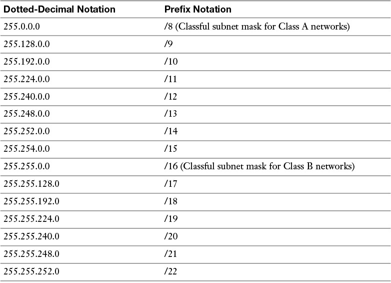
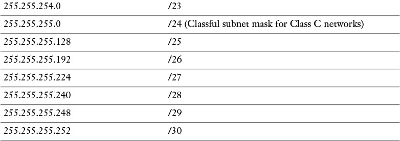
Table 5-22 Dotted-Decimal and Prefix-Notation Representations for IPv4 Subnets
Recall that any octet with a value of 255 contains eight 1s. Also, you should memorize valid octet values for an octet and the corresponding number of 1s (that is, continuous, left-justified 1s) in that octet, as shown in Table 5-23. Based on this information, you should be able to see the dotted-decimal notation of a subnet mask and quickly determine the corresponding prefix notation.
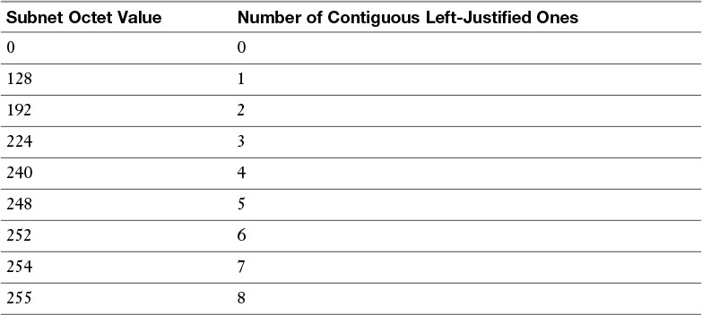
Table 5-23 Subnet Octet Values
For example, consider the subnet mask of 255.255.192.0. Because each of the first two octets has a value of 255, you know that you have 16 1s from the first two octets. You then recall that a value of 192 in the third octet requires two 1s from that octet. By adding the 16 1s from the first two octets to the two 1s from the third octet, you can determine that the subnet mask of 255.255.192.0 has a corresponding prefix notation of /18.
To help you develop the skill of making these calculations quickly, work through the following two exercises.
Subnet Notation: Practice Exercise 1
Given a subnet mask of 255.255.255.248, what is the corresponding prefix notation? __________________
Subnet Notation: Practice Exercise 1 Solution
Given a subnet mask of 255.255.255.248, you should recognize that the first three octets, each containing a value of 255, represent 24 1s. To those 24 1s, you add five additional 1s, based on your memorization of how many contiguous, left-justified 1s in an octet are required to produce various octet values. The sum of 24 bits (from the first three octets) and the 5 bits (from the fourth octet) give you a total of 29 bits. Therefore, you can conclude that a subnet mask with a dotted-decimal notation of 255.255.255.248 has an equivalent prefix notation of /29.
Subnet Notation: Practice Exercise 2
Given a subnet mask of /17, what is the corresponding dotted-decimal notation? __________________
Subnet Notation: Practice Exercise 2 Solution
You know that each octet contains 8 bits. So, given a subnet mask of /17, you can count by 8s to determine that there are eight 1s in the first octet, eight 1s in the second octet, and one 1 in the third octet. You already knew that an octet containing all 1s has a decimal value of 255. From that knowledge, you conclude that each of the first two octets has a value of 255. Also, based on your memorization of Table 5-23, you know that one 1 (that is, a left-justified 1) in an octet has a decimal equivalent value of 128. Therefore, you can conclude that a subnet mask with a prefix notation of /17 can be represented in dotted-decimal notation as 255.255.128.0.
Extending a Classful Mask
The way to take a classful network (that is, a network using a classful subnet mask) and divide that network into multiple subnets is by adding 1s to the network’s classful subnet mask. However, the class of the IP address does not change, regardless of the new subnet mask. For example, if you took the 172.16.0.0/16 network and subnetted it into multiple networks using a 24-bit subnet mask (172.16.0.0/24, 172.16.1.0/24, 172.16.2.0/24, ...), those networks would still be Class B networks.)
Specifically, the class of a network is entirely determined by the value of the first octet. The class of a network has nothing to do with the number of bits in a subnet, making this an often-misunderstood concept.
As another example, the network 10.2.3.0/24 has the classful subnet mask of a Class C network (that is, a 24-bit subnet mask). However, the 10.2.3.0/24 network is a Class A network because the value of the first octet is 10. It is simply a Class A network that happens to have a 24-bit subnet mask.
Borrowed Bits
When you add bits to a classful mask, the bits you add are referred to as borrowed bits. The number of borrowed bits you use determines how many subnets are created and the number of usable hosts per subnet.
Calculating the Number of Created Subnets
To determine the number of subnets created when adding bits to a classful mask, you can use the following formula:
Number of created subnets = 2s
where s is the number of borrowed bits
For example, let’s say you subnetted the 192.168.1.0 network with a 28-bit subnet mask, and you want to determine how many subnets were created. First, you determine how many borrowed bits you have. Recall that the number of borrowed bits is the number of bits in a subnet mask beyond the classful mask. In this case, because the first octet in the network address has a value of 192, you can conclude that this is a Class C network. You also recall that a Class C network has 24 bits in its classful (that is, its default) subnet mask. Because you now have a 28-bit subnet mask, the number of borrowed bits can be calculated as follows:
Number of borrowed bits = Bits in custom subnet mask – Bits in classful subnet mask
Number of borrowed bits = 28 – 24 = 4
Now that you know you have 4 borrowed bits, you can raise 2 to the power of 4 (24, or 2 * 2 * 2 * 2), which equals 16. From this calculation, you conclude that subnetting the 192.168.1.0/24 with a 28-bit subnet mask yields 16 subnets.
Calculating the Number of Available Hosts
Earlier in this section, you were exposed to the formula for calculating the number of available (that is, assignable) host IP addresses, based on the number of host bits in a subnet mask. The formula was
Number of assignable IP address in a subnet = 2h – 2
where h is the number of host bits in the subnet mask
Using the previous example, let’s say you want to determine the number of available host IP addresses in one of the 192.168.1.0/28 subnets. First, you need to determine the number of host bits in the subnet mask. Because you know that an IPv4 address consists of 32 bits, you can subtract the number of bits in the subnet mask (28, in this example) from 32 to determine the number of host bits:
Number of host bits = 32 – Number of bits in subnet mask
Number of host bits = 32 – 28 = 4
Now that you know the number of host bits, you can apply it to the previously presented formula:
Number of assignable IP addresses in a subnet = 2h – 2
where h is the number of host bits in the subnet mask
Number of assignable IP addresses in a subnet = 24 – 2 = 16 – 2 = 14
From this calculation, you can conclude that each of the 192.168.1.0/28 subnets has 14 usable IP addresses.
To reinforce your skill with these calculations, you are now challenged with a few practice exercises.
Basic Subnetting Practice: Exercise 1
Using a separate sheet of paper, solve the following scenario:
Your company has been assigned the 172.20.0.0/16 network for use at one of its sites. You need to use a subnet mask that will accommodate 47 subnets while simultaneously accommodating the maximum number of hosts per subnet. What subnet mask will you use?
Basic Subnetting Practice: Exercise 1 Solution
To determine how many borrowed bits are required to accommodate 47 subnets, you can write out a table that shows the powers of 2, as shown in Table 5-24. In fact, you might want to sketch out a similar table on the dry-erase card you are given when you take the Network+ exam.
Table 5-24 Number of Subnets Created by a Specified Number of Borrowed Bits
In this example, where you want to support 47 subnets, 5 borrowed bits are not enough, and 6 borrowed bits are more than enough. Because 5 borrowed bits are not enough, you round up and use 6 borrowed bits.
The first octet in the network address 172.20.0.0 has a value of 172, meaning that you are dealing with a Class B address. Because a Class B address has 16 bits in its classful mask, you can add the 6 borrowed bits to the 16-bit classful mask, which results in a 22-bit subnet mask.
One might argue that although a 22-bit subnet mask would accommodate 47 subnets, so would a 23-bit subnet mask or a 24-bit subnet mask. Although that is true, recall that the scenario said you should have the maximum number of hosts per subnet. This suggests that you should not use more borrowed bits than necessary. Therefore, you can conclude that to meet the scenario’s requirements, you should use a subnet mask of /22, which could also be written as 255.255.252.0.
Basic Subnetting Practice: Exercise 2
Using a separate sheet of paper, solve the following scenario:
Your company has been assigned the 172.20.0.0/16 network for use at one of its sites. You need to calculate a subnet mask that will accommodate 100 hosts per subnet while maximizing the number of available subnets. What subnet mask will you use?
Basic Subnetting Practice: Exercise 2 Solution
To determine how many host bits are required to accommodate 100 hosts, you can write out a table that shows the number of hosts supported by a specific number of hosts bits, as shown in Table 5-25. Like the previous table, you might want to sketch out a similar table on the dry-erase card you are given when taking the Network+ exam.
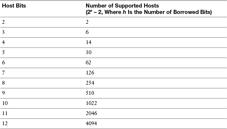
Table 5-25 Number of Supported Hosts Given a Specified Number of Host Bits
In this example, where you want to support 100 subnets, 6 host bits are not enough, and 7 host bits are more than enough. Because 6 host bits are not enough, you round up and use 7 host bits.
Because an IPv4 address has 32 bits and you need 7 host bits, you can calculate the number of subnet bits by subtracting the 7 host bits from 32 (that is, the total number of bits in an IPv4 address). This results in a 25-bit subnet mask (that is, 32 total bits – 7 host bits = 25 subnet mask bits). Therefore, you can conclude that to meet the scenario’s requirements, you should use a subnet mask of /25, which could also be written as 255.255.255.128.
Calculating New IP Address Ranges
Now that you can calculate the number of subnets created based on a given number of borrowed bits, the next logical step is to calculate the IP address ranges making up those subnets. For example, if you took the 172.25.0.0/16 and subnetted it with a 24-bit subnet mask, the resulting subnets would be as follows:
172.25.0.0/24
172.25.1.0/24
172.25.2.0/24
...
172.25.255.0/24
Let’s consider how such a calculation is performed. Notice in the previous example that you count by 1 in the third octet to calculate the new networks. To determine in what octet you start counting and by want increment you count, a new term needs to be defined. The interesting octet is the octet containing the last 1 in the subnet mask.
In this example, the subnet mask was a 24-bit subnet mask, which has a dotted-decimal equivalent of 255.255.255.0 and a binary equivalent of 11111111.11111111.11111111.00000000. From any of these subnet mask representations, you can determine that the third octet is the octet to contain the last 1 in the subnet mask. Therefore, you will be changing the value of the third octet to calculate the new networks.
Now that you know the third octet is the interesting octet, you need to know by what increment you will be counting in that octet. This increment is known as the block size. The block size can be calculated by subtracting the subnet mask value in the interesting octet from 256. In this example, the subnet mask had a value of 255 in the interesting octet (that is, the third octet). If you subtract 255 from 256, you get a result of 1 (that is, 256 – 255 = 1). The first subnet will be the original network address, with all of the borrowed bits set to 0. After this first subnet, you start counting by the block size (1, in this example) in the interesting octet to calculate the remainder of the subnets.
The preceding steps for calculating subnets can be summarized as follows:
Step 1. Determine the interesting octet by determining the last octet in the subnet mask to contain a 1.
Step 2. Determine the block size by subtracting the decimal value in the subnet’s interesting octet from 256.
Step 3. Determine the first subnet by setting all the borrowed bits (which are bits in the subnet mask beyond the bits in the classful subnet mask) to 0.
Step 4. Determine additional subnets by taking the first subnet and counting by the block size increment in the interesting octet.
To reinforce this procedure, consider another example. A 27-bit subnet mask is applied to a network address of 192.168.10.0/24. To calculate the created subnets, you can perform the following steps:
Step 1. The subnet mask (in binary) is 11111111.11111111.11111111.11100000. The interesting octet is the fourth octet because the fourth octet contains the last 1 in the subnet mask.
Step 2. The decimal value of the fourth octet in the subnet mask is 224 (11100000 in decimal). Therefore, the block size is 32 (256 – 224 = 32).
Step 3. The first subnet is 192.168.10.0/27 (the value of the original 192.168.10.0 network with the borrowed bits [the first three bits in the fourth octet] set to 0).
Step 4. Counting by 32 (the block size) in the interesting octet (the fourth octet) allows you to calculate the remaining subnets:
192.168.10.0
192.168.10.32
192.168.10.64
192.168.10.96
192.168.10.128
192.168.10.160
192.168.10.192
192.168.10.224
Now that you know the subnets created from a classful network given a subnet mask, the next logical step is to determine the usable addresses within those subnets. Recall that you cannot assign an IP address to a device if all the host bits in the IP address are set to 0, because an IP address with all host bits set to 0 is the address of the subnet itself.
Similarly, you cannot assign an IP address to a device if all the host bits in the IP address are set to 1 because an IP address with all host bits set to 1 is the directed broadcast address of a subnet.
By excluding the network and directed broadcast addresses from the 192.168.10.0/27 subnets (as previously calculated), the usable addresses shown in Table 5-26 can be determined.
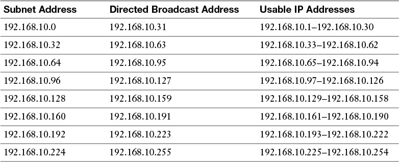
Table 5-26 Usable IP Address Ranges for the 192.168.10.0/27 Subnets
To help develop your subnet-calculation skills, you are now challenged with a few practice subnetting exercises.
Advanced Subnetting Practice: Exercise 1
Using a separate sheet of paper, solve the following scenario:
Based on your network design requirements, you determine that you should use a 26-bit subnet mask applied to your 192.168.0.0/24 network. You now need to calculate each of the created subnets. Additionally, you want to know the broadcast address and the range of usable addresses for each of the created subnets.
Advanced Subnetting Practice: Exercise 1 Solution
As described earlier, you can go through the following four-step process to determine the subnet address:
Step 1. The subnet mask (in binary) is 11111111.11111111.11111111.11000000. The interesting octet is the fourth octet because the fourth octet contains the last 1 in the subnet mask.
Step 2. The decimal value of the fourth octet in the subnet mask is 192 (11000000 in decimal). Therefore, the block size is 64 (256 – 192 = 64).
Step 3. The first subnet is 192.168.0.0/26 (the value of the original 192.168.0.0 network with the borrowed bits [the first 2 bits in the last octet] set to 0).
Step 4. Counting by 64 (the block size) in the interesting octet (the fourth octet) allows you to calculate the remaining subnets, resulting in the following subnets:
192.168.0.0
192.168.0.64
192.168.0.128
192.168.0.192
The directed broadcast addresses for each of the preceding subnets can be calculated by adding 63 (that is, one less than the block size) to the interesting octet for each subnet address. Excluding the subnet addresses and directed broadcast addresses, a range of usable addresses can be calculated, the results of which are seen in Table 5-27.
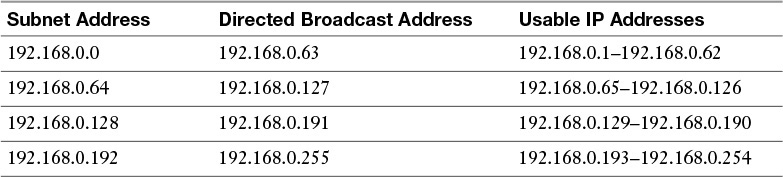
Table 5-27 Usable IP Address Ranges for the 192.168.0.0/26 Subnets
Advanced Subnetting Practice: Exercise 2
Using a separate sheet of paper, solve the following scenario:
The network shown in Figure 5-18 has subnetted the 172.16.0.0/16 network by using a 20-bit subnet mask. Notice that two VLANs (two subnets) are currently configured; however, one of the client PCs is assigned an IP address that is not in that PC’s VLAN. Which client PC is assigned an incorrect IP address?
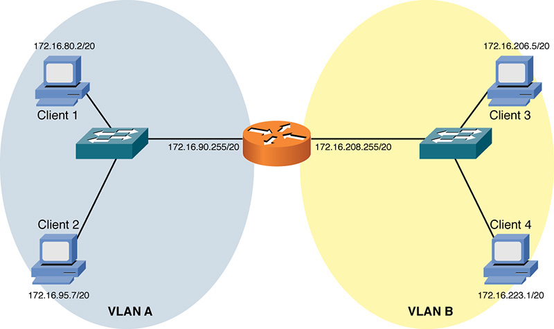
Figure 5-18 Topology for Advanced Subnetting Practice: Exercise 2
Advanced Subnetting Practice: Exercise 2 Solution
To determine which client PC is assigned an IP address outside of its local VLAN, you need to determine the subnets created by the 20-bit subnet mask applied to the 172.16.0.0/16 network:
1. The interesting octet for a 20-bit subnet mask is the third octet because the third octet is the last octet to contain a 1 in the 20-bit subnet mask (11111111.11111111.11110000.00000000, which could also be written as 255.255.240.0).
2. The decimal value of the third octet in the subnet mask is 240. Therefore, the block size is 16 (256 – 240 = 16).
3. The first 172.16.0.0/20 subnet is 172.16.0.0 (172.16.0.0/20 with the 4 borrowed bits in the third octet set to 0).
4. Beginning with the first subnet of 172.16.0.0/20 and counting by the block size of 16 in the interesting octet yields the following subnets:
172.16.0.0/20
172.16.16.0/20
172.16.32.0/20
172.16.48.0/20
172.16.64.0/20
172.16.80.0/20
172.16.96.0/20
172.16.112.0/20
172.16.128.0/20
172.16.144.0/20
172.16.160.0/20
172.16.176.0/20
172.16.192.0/20
172.16.208.0/20
172.16.224.0/20
172.16.240.0/20
Based on the IP addresses of the router interfaces, you can determine the subnets for VLAN A and VLAN B. Specifically, the router interface in VLAN A has an IP address of 172.16.90.255/20. Based on the previous listing of subnets, you can determine that this interface resides in the 172.16.80.0/20 network, whose range of usable addresses is 172.16.80.1–172.16.95.254. Then you can examine the IP addresses of Client 1 and Client 2 to determine whether their IP addresses reside in that range of usable addresses.
Similarly, for VLAN B, the router’s interface has an IP address of 172.16.208.255/20. Based on the previous subnet listing, you notice that this interface has an IP address that is part of the 172.16.208.0/20 subnet. As you did for VLAN A, you can check the IP address of Client 3 and Client 4 to determine whether their IP addresses reside in VLAN B’s range of usable IP addresses (that is, 172.16.208.1–172.16.223.254).
Table 5-28 shows these comparisons.
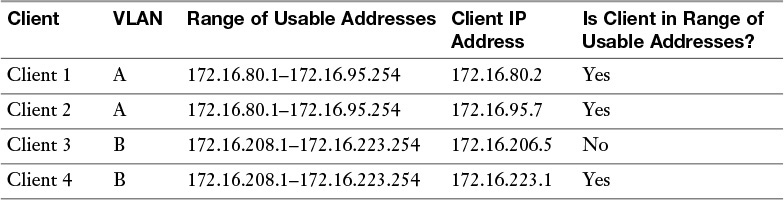
Table 5-28 IP Address Comparison for Advanced Subnetting Practice: Exercise 2
The comparison in Table 5-28 reveals that Client 3 (with an IP address of 172.16.206.5) does not have an IP address in VLAN B’s subnet (with a usable address range of 172.16.208.1–172.16.223.254).
Additional Practice
If you want to continue practicing these concepts, make up your own subnet mask and apply it to a classful network of your choosing. Then you can calculate the created subnets, the directed broadcast IP address for each subnet, and the range of usable IP addresses for each subnet.
To check your work, you can use a subnet calculator. An example of such a calculator is the free subnet calculator available for download from http://www.solarwinds.com/downloads, as shown in Figure 5-19.
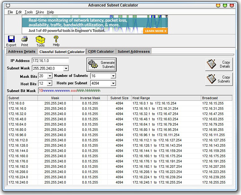
Figure 5-19 Free Subnet Calculator
Note
As you read through different networking literature, you might come across other approaches to performing subnetting. Various shortcuts exist (including the one presented in this chapter), and some approaches involve much more binary math. The purpose of this section was not to be an exhaustive treatment of all available subnetting methods, but to provide a quick and easy approach to performing subnet calculations in the real world and on the Network+ certification exam.
Classless Interdomain Routing
Although subnetting is the process of extending a classful subnet mask (that is, adding 1s to a classful mask), classless interdomain routing (CIDR) does just the opposite. Specifically, CIDR shortens a classful subnet mask by removing 1s from the classful mask. As a result, CIDR allows contiguous classful networks to be aggregated. This process is sometimes called route aggregation.
A typical use of CIDR is a service provider summarizing multiple Class C networks, assigned to their various customers. For example, imagine that a service provider is responsible for advertising the following Class C networks:
192.168.32.0/24
192.168.33.0/24
192.168.34.0/24
192.168.35.0/24
The service provider could advertise all four networks with a single route advertisement of 192.168.32.0/22. To calculate this advertisement, convert the values in the third octet (that is, the octet where the values start to differ) to binary, as shown in Figure 5-20. Then determine how many bits the networks have in common. The number of common bits then becomes the number of bits in the CIDR mask.
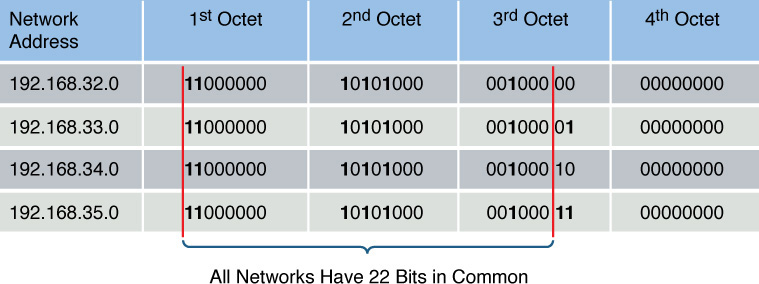
Figure 5-20 CIDR Calculation Example
Because all four of the network addresses have the first 22 bits in common, and because setting the remaining bits to 0 (11000000.10101000.00100000.00000000) creates a network address of 192.168.32.0, these networks can be summarized as 192.168.32.0/22.
IP Version 6
With the global proliferation of IP-based networks, available IPv4 addresses are rapidly becoming extinct. Fortunately, IPv6 provides enough IP addresses for many generations to come. This section introduces IPv6’s address structure and discusses some of its unique characteristics.
Need for IPv6
With the worldwide depletion of IP Version 4 (IPv4) addresses, many organizations have migrated, are in the process of migrating, or are considering migrating their IPv4 addresses to IPv6 addresses. IPv6 dramatically increases the number of available IP addresses. In fact, IPv6 offers approximately 5 * 1028 IP addresses for each person on the planet.
Beyond the increased address space, IPv6 offers many other features:
![]() Simplified header
Simplified header
![]() IPv4 header uses 12 fields
IPv4 header uses 12 fields
![]() IPv6 header uses 5 fields
IPv6 header uses 5 fields
![]() No broadcasts
No broadcasts
![]() No fragmentation (performs MTU discovery for each session)
No fragmentation (performs MTU discovery for each session)
![]() Can coexist with IPv4 during a transition
Can coexist with IPv4 during a transition
![]() Dual stack (running IPv4 and IPv6 simultaneously)
Dual stack (running IPv4 and IPv6 simultaneously)
![]() IPv6 over IPv4 (tunneling IPv6 over an IPv4 tunnel)
IPv6 over IPv4 (tunneling IPv6 over an IPv4 tunnel)
Even if you are designing a network based on IPv4 addressing, a good practice is to consider how readily an IPv6 addressing scheme could be overlaid on that network at some point in the future. Using Teredo tunneling, an IPv6 host could provide IPv6 connectivity even when the host is directly connected to an IPv4-only network. Miredo is a client that can be used to implement the Teredo protocol and is included in many versions of Linux. IPv6/IPv4 tunneling is often referred to as 6to4 or 4to6 tunneling, depending on which protocol is being tunneled (IPv4 or IPv6).
IPv6 Address Structure
An IPv6 address has the following address format, where X = a hexadecimal digit in the range of 0 to F:
XXXX:XXXX:XXXX:XXXX:XXXX:XXXX:XXXX:XXXX
A hexadecimal digit is 4 bits in size (4 binary bits can represent 16 values). Notice that an IPv6 address has eight fields, and each field contains four hexadecimal digits. The following formula reveals why an IPv6 address is a 128-bit address:
4 bits per digit * 4 digits per field * 8 fields = 128 bits in an IPv6 address
IPv6 addresses can be difficult to work with because of their size. Fortunately, the following rules exist for abbreviating these addresses:
![]() Leading 0s in a field can be omitted.
Leading 0s in a field can be omitted.
![]() Contiguous fields containing all 0s can be represented with a double colon. (Note that this can be done only once for a single IPv6 address.)
Contiguous fields containing all 0s can be represented with a double colon. (Note that this can be done only once for a single IPv6 address.)
For example, consider the following IPv6 address:
ABCD:0123:4040:0000:0000:0000:000A:000B
Using the rules for abbreviation, the IPv6 address can be rewritten as follows:
ABCD:123:4040::A:B
Also, the Extended Unique Identifier (EUI-64) format can be used to cause a router to automatically populate the low-order 64 bits of an IPv6 address based on an interface’s MAC address.
IPv6 Address Types
IPv6 globally routable unicast addresses start with the first 4 hex characters in the range of 2000 to 3999. An IPv6 link-local address is also used on each IPv6 interface. The link-local address begins with FE80. The multicast addresses begin with FF as the first two hex characters. IPv6 can use autoconfiguration to discover the current network and select a host ID that is unique on that network. IPv6 can also use a special version of DHCP for IPv6. The protocol that is used to discover the network address and learn the Layer 2 address of neighbors on the same network is Neighbor Discovery Protocol (NDP).
IPv6 Data Flows
IPv6 has three types of data flows:
![]() Unicast
Unicast
![]() Multicast
Multicast
![]() Anycast
Anycast
The following sections summarize the characteristics of each address type.
Unicast
With unicast, a single IPv6 address is applied to a single interface, as illustrated in Figure 5-21. The communication flow can be thought of as a one-to-one communication flow.
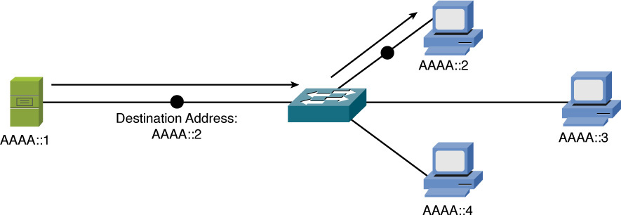
Figure 5-21 IPv6 Unicast Example
In Figure 5-21, a server (AAAA::1) is sending traffic to a single client (AAAA::2).
Multicast
With multicast, a single IPv6 address (a multicast group) can represent multiple devices on a network, as shown in Figure 5-22. The communication flow is a one-to-many communication flow.
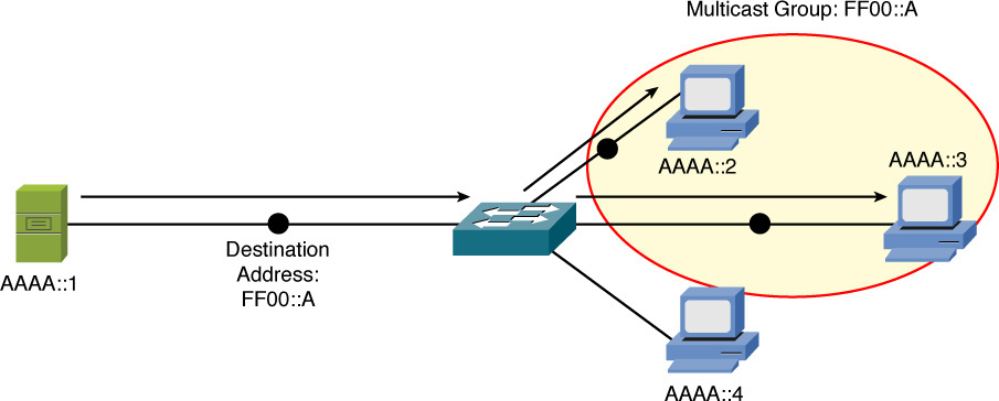
Figure 5-22 IPv6 Multicast Example
In Figure 5-22, a server (AAAA::1) is sending traffic to a multicast group (FF00::A). Two clients (AAAA::2 and AAAA::3) have joined this group. Those clients receive the traffic from the server, while any client that did not join the group (for example, AAAA::4) does not receive the traffic.
Anycast
With anycast, a single IPv6 address is assigned to multiple devices, as depicted in Figure 5-23. It’s a one-to-nearest (from the perspective of a router’s routing table) communication flow.
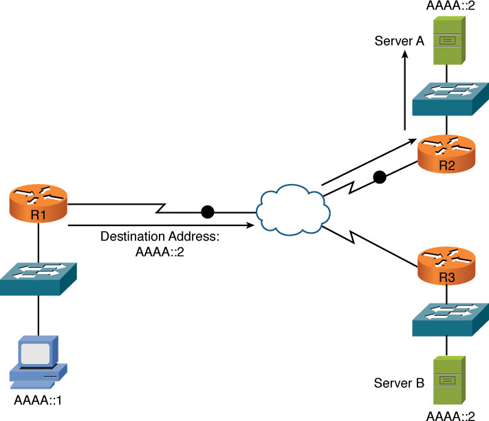
Figure 5-23 IPv6 Anycast Example
In Figure 5-23, a client with an IPv6 address of AAAA::1 wants to send traffic to a destination IPv6 address of AAAA::2. Notice that two servers (server A and server B) have an IPv6 address of AAAA::2. In the figure, the traffic destined for AAAA::2 is sent to server A, via router R2, because the network on which server A resides appears to be closer than the network on which server B resides, from the perspective of router R1’s IPv6 routing table.
Real-World Case Study
Acme Inc. has decided to use private IP addresses for their internal LAN and for the WAN. They will use the private block of 10.0.0.0/8 and create subnets to provide enough subnets to cover the number of VLANs they will be using on the LANs at the headquarters site and at each of the remote offices. The association between the Layer 2 VLANs and the Layer 3 IP subnets will be one to one, with each VLAN having its own subnet associated with it.
The company will have nine VLANs and will use a couple subnets for the WAN connections. For the VLANs, they plan to use a network mask of /12, which will provide enough subnets to meet their needs based on the starting mask of /8 for the Class A private address of 10.0.0.0/8.
For the WAN connectivity that they are purchasing from a service provider for connectivity between the remote branch offices and the headquarters site, they will use masks of /30, which will allow for two hosts on each of the WAN connections, which is enough for each device at the end of the point-to-point WAN connections.
To connect their LANs to the Internet, they plan to use Network Address Translation (NAT), which is going to be performed by their service provider so that traffic going to the Internet will appear to be coming from a globally routable IP address and not from a private address (more about NAT in Chapter 6).
Summary
The main topics covered in this chapter are the following:
![]() The binary math tutorial gave you a basic understanding of why binary math is necessary for working with subnet masks.
The binary math tutorial gave you a basic understanding of why binary math is necessary for working with subnet masks.
![]() The characteristics of IPv4 were presented, including IPv4’s address format and a contrast of unicast, broadcast, and multicast data flows.
The characteristics of IPv4 were presented, including IPv4’s address format and a contrast of unicast, broadcast, and multicast data flows.
![]() You examined various approaches for assigning IP address information to network devices. These approaches included static assignment, dynamic assignment (BOOTP and DHCP), and APIPA (a Zeroconf component).
You examined various approaches for assigning IP address information to network devices. These approaches included static assignment, dynamic assignment (BOOTP and DHCP), and APIPA (a Zeroconf component).
![]() Multiple examples and practice exercises were provided for various subnet calculations.
Multiple examples and practice exercises were provided for various subnet calculations.
![]() The characteristics of IPv6 were highlighted, including the IPv6 address format and IPv6 data flows (unicast, multicast, and anycast).
The characteristics of IPv6 were highlighted, including the IPv6 address format and IPv6 data flows (unicast, multicast, and anycast).
Exam Preparation Tasks
Review All the Key Topics
Review the most important topics from inside the chapter, noted with the Key Topic icon in the outer margin of the page. Table 5-29 lists these key topics and the page numbers where each is found.
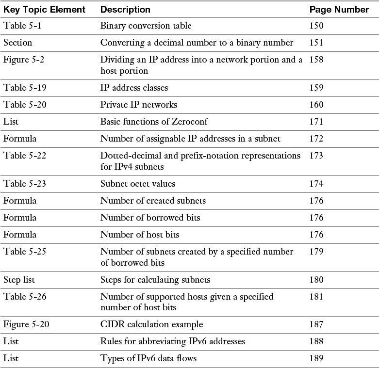
Table 5-29 Key Topics for Chapter 5
Complete Tables and Lists from Memory
Print a copy of Appendix D, “Memory Tables” (found on the DVD), or at least the section for this chapter, and complete the tables and lists from memory. Appendix E, “Memory Table Answer Key,” also on the DVD, includes the completed tables and lists so you can check your work.
Define Key Terms
Define the following key terms from this chapter, and check your answers in the Glossary:
classful masks
private IP addresses
octet
prefix notation
slash notation
dotted-decimal notation
classful mask
default gateway
Bootstrap Protocol
Dynamic Host Configuration Protocol (DHCP)
Zeroconf
link-local IP address
Automatic Private IP Addressing
borrowed bits
block size
classless interdomain routing (CIDR)
unicast
multicast
anycast
Complete Chapter 5 Hands-On Labs in Network+ Simulator Lite
![]() IPv4 Address Types and Classes
IPv4 Address Types and Classes
![]() Configuring a Client Network Adapter with an IPv4 Address
Configuring a Client Network Adapter with an IPv4 Address
Review Questions
The answers to these review questions are in Appendix A, “Answers to Review Questions.”
1. What is the binary representation of the decimal number 117?
a. 10110101
b. 01110101
c. 10110110
d. 01101001
2. The binary number 10110100 has what decimal equivalent?
a. 114
b. 190
c. 172
d. 180
3. What is the class of IP address 10.1.2.3/24?
a. Class A
b. Class B
c. Class C
d. Class D
4. Which of the following statements are true regarding VLANs? (Choose two.)
a. A VLAN is a single Layer 2 broadcast domain.
b. For traffic to pass between two VLANs, that traffic must be routed by a Layer 3 device.
c. Because of a switch’s MAC address table, traffic does not need to be routed in order to pass between two VLANs.
d. A VLAN is a single collision domain.
5. Which of the following are dynamic approaches to assigning routable IP addresses to networked devices? (Choose two.)
a. BOOTP
b. APIPA
c. Zeroconf
d. DHCP
6. How many assignable IP addresses exist in the 172.16.1.10/27 network?
a. 30
b. 32
c. 14
d. 64
7. What is the prefix notation for a subnet mask of 255.255.255.240?
a. /20
b. /24
c. /28
d. /29
8. Your company has been assigned the 192.168.30.0/24 network for use at one of its sites. You need to use a subnet mask that will accommodate seven subnets while simultaneously accommodating the maximum number of hosts per subnet. What subnet mask should you use?
a. /24
b. /26
c. /27
d. /28
9. A client with an IP address of 172.16.18.5/18 belongs to what network?
a. 172.16.0.0/18
b. 172.16.64.0/18
c. 172.16.96.0/18
d. 172.16.128.0/18
10. How can the following IPv6 address be condensed?
2009:0123:4040:0000:0000:000:000A:100B
a. 2009::123:404:A:100B
b. 2009::123:404:A:1B
c. 2009:123:4040::A:100B
d. 2009:0123:4040::0::000A:100B
All materials on the site are licensed Creative Commons Attribution-Sharealike 3.0 Unported CC BY-SA 3.0 & GNU Free Documentation License (GFDL)
If you are the copyright holder of any material contained on our site and intend to remove it, please contact our site administrator for approval.
© 2016-2026 All site design rights belong to S.Y.A.