CompTIA Network+ N10-006 Cert Guide (2015)
Chapter 7. Wide-Area Networks
After completion of this chapter, you will be able to answer the following questions:
![]() What are three categories of wide-area network (WAN) connections?
What are three categories of wide-area network (WAN) connections?
![]() How are data rates measured on various WAN technologies?
How are data rates measured on various WAN technologies?
![]() Which types of media (or wireless technologies) might be used in WAN connections?
Which types of media (or wireless technologies) might be used in WAN connections?
![]() What are the characteristics of the following WAN technologies: dedicated leased line, digital subscriber line (DSL), cable modem, Synchronous Optical Network (SONET), satellite, plain old telephone service (POTS), Integrated Services Digital Network (ISDN), Frame Relay, Asynchronous Transfer Mode (ATM), and Multiprotocol Label Switching (MPLS)?
What are the characteristics of the following WAN technologies: dedicated leased line, digital subscriber line (DSL), cable modem, Synchronous Optical Network (SONET), satellite, plain old telephone service (POTS), Integrated Services Digital Network (ISDN), Frame Relay, Asynchronous Transfer Mode (ATM), and Multiprotocol Label Switching (MPLS)?
The Pareto principle states that roughly 80 percent of the effects come from 20 percent of the causes. In the early 1990s, computer-networking design guides invoked the Pareto principle and stated that 80 percent of your network traffic stays local, whereas only 20 percent of your network traffic leaves the local network. This was an information technology (IT) extrapolation of Vilfredo Pareto’s 80-20 rule. With the advent of Internet browsers, cloud storage, and streaming audio and video, today’s network traffic patterns are more closely approximated with a 20-80 rule, meaning that the vast majority of network traffic leaves the local network over a wide-area network (WAN) connection.
As defined in Chapter 1, “Computer Network Fundamentals,” a WAN is a network that spans large geographical distances. This chapter discusses the properties of WAN connections, followed by a survey of common WAN technologies.
Foundation Topics
WAN Properties
To select an appropriate WAN technology for a network you are designing or to better understand a WAN technology in a currently installed network, you need the ability to compare one WAN technology to another. This section identifies a collection of WAN connection properties that can be used to contrast various WAN technologies.
WAN Connection Types
Some WAN connections are considered to be always on, in that the connection is always available without having to first set up the connection. Conversely, some WAN technologies are on demand, meaning that the connection is not established until needed. Then, when the connection is needed, it is brought up.
Another distinguishing characteristic of WAN connections is whether multiple users share bandwidth. For example, some WAN connections provide dedicated bandwidth to a service provider’s customer, while other WAN connections allow multiple customers of a service provider to share a common pool of available bandwidth.
A WAN connection can generally be classified into one of three categories: a dedicated leased line, a circuit-switched connection, or a packet-switched connection:

![]() Dedicated leased line: A connection interconnecting two sites. This logical connection might physically connect through a service provider’s facility or a telephone company’s central office (CO). The expense of a dedicated leased line is typically higher than other WAN technologies offering similar data rates because with a dedicated leased line, a customer does not have to share bandwidth with other customers.
Dedicated leased line: A connection interconnecting two sites. This logical connection might physically connect through a service provider’s facility or a telephone company’s central office (CO). The expense of a dedicated leased line is typically higher than other WAN technologies offering similar data rates because with a dedicated leased line, a customer does not have to share bandwidth with other customers.
As discussed in the section, “WAN Technologies,” a T1 circuit, as shown in Figure 7-1, is an example of a dedicated leased line technology commonly found in North America. A common Layer 2 protocol that could run over a dedicated leased line is Point-to-Point Protocol (PPP), which is discussed later in this chapter.
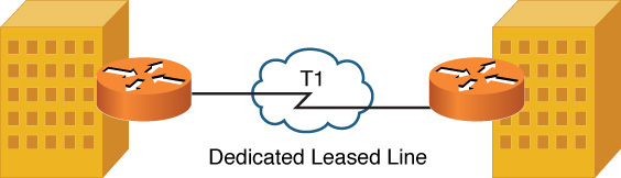
Figure 7-1 Dedicated Leased Line Sample Topology
![]() Circuit-switched connection: A connection that is brought up on an as-needed basis. In fact, a circuit-switched connection is analogous to a phone call, where you pick up your phone, dial a number, and a connection is established based on the number you dial. As discussed later in this chapter, Integrated Services Digital Network (ISDN) can operate as a circuit-switched connection, bringing up a virtual circuit (VC) on demand. This approach to on-demand bandwidth can be a cost savings for some customers who only need periodic connectivity to a remote site. Figure 7-2 illustrates a circuit-switched connection.
Circuit-switched connection: A connection that is brought up on an as-needed basis. In fact, a circuit-switched connection is analogous to a phone call, where you pick up your phone, dial a number, and a connection is established based on the number you dial. As discussed later in this chapter, Integrated Services Digital Network (ISDN) can operate as a circuit-switched connection, bringing up a virtual circuit (VC) on demand. This approach to on-demand bandwidth can be a cost savings for some customers who only need periodic connectivity to a remote site. Figure 7-2 illustrates a circuit-switched connection.
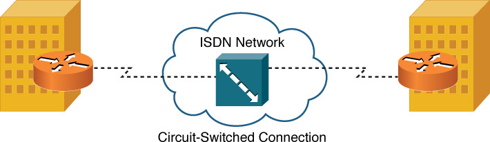
Figure 7-2 Circuit-Switched Connection Sample Topology
![]() Packet-switched connection: Similar to a dedicated leased line because most packet-switched networks are always on. However, unlike a dedicated leased line, packet-switched connections allow multiple customers to share a service provider’s bandwidth.
Packet-switched connection: Similar to a dedicated leased line because most packet-switched networks are always on. However, unlike a dedicated leased line, packet-switched connections allow multiple customers to share a service provider’s bandwidth.
Even though bandwidth is being shared among customers, customers can purchase a service-level agreement (SLA), which specifies performance metrics (for example, available bandwidth and maximum delay) guaranteed for a certain percentage of time. For example, an SLA might guarantee a customer that he has a minimum of 5 Mbps of bandwidth available 80 percent of the time.
Frame Relay, which is discussed in the section, “WAN Technologies,” is an example of a packet-switched connection. As shown in Figure 7-3, a Frame Relay network allows multiple customers to connect to a service provider’s network, and virtual circuits (VCs, as indicated with the dashed lines) logically interconnect customer sites.
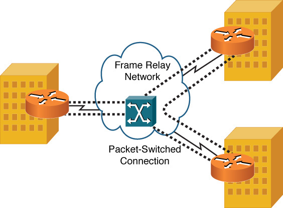
Figure 7-3 Packet-Switched Connection Sample Topology
Asynchronous Transfer Mode (ATM) is often categorized as a packet-switched connection. However, to be technically accurate, ATM is a cell-switched connection because ATM uses fixed-length (that is, 53 byte) cells, as opposed to variable-length frames.
Note
These connection types are meant to be general categories, and not all WAN technologies will strictly meet the previous definitions. For example, digital subscriber line (DSL) is a technology that could be configured for on-demand access (like a circuit-switched connection), or it could be configured for always-on access. Also, DSL typically provides a customer with an amount of bandwidth that the customer does not have to share with other customers (like a dedicated leased line). However, DSL uses ATM technologies to connect back to the service provider’s equipment (like a cell-switched connection). So, use these three categories of WAN connection types as general guidelines, not strict definitions.
WAN Data Rates
LAN links are typically faster than WAN links; however, some WAN technologies (for example, Synchronous Optical Network [SONET]) boast a bandwidth capacity in the tens of gigabits per second (Gbps). One could argue that some of these higher-speed WAN technologies are actually metropolitan-area network (MAN) technologies. However, this chapter considers a WAN to be an interconnection of geographically dispersed networks that also encompass MAN technologies.
Aside from measuring bandwidth in kilobits per second (Kbps), megabits per second (Mbps), or gigabits per second (Gbps), high-speed optical networks often use optical carrier (OC) levels to indicate bandwidth. As a base reference point, the speed of an OC-1 link is 51.84 Mbps. Other OC levels are simply multiples of an OC-1. For example, an OC-3 link has three times the bandwidth of an OC-1 link (that is, 3 * 51.84 Mbps = 155.52 Mbps).
Although a variety of speeds are available from different service providers, Table 7-1 offers typical bandwidths of several common WAN technologies.
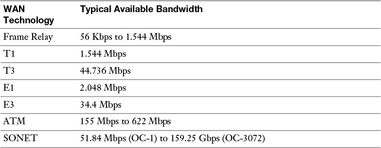
Table 7-1 Typical WAN Data Rates
WAN Media Types
WAN links might be physical hard-wired links (for example, copper or fiber-optic cable running from your site back to your service provider’s site and then to the remote site with which your site communicates). Alternatively, some WAN links are wireless. These wireless solutions might be appropriate for locations where more conventional WAN technologies are unavailable or for accommodating the needs of mobile users.
Physical Media
The physical media used for WAN connections is similar to the physical media found in LAN connections:
![]() Unshielded twisted pair (UTP): Both analog and digital circuits coming into your location from a local telephone central office commonly use UTP cabling. This cabling might be Category 3 (Cat 3) cabling, as opposed to higher categories used in LANs. Examples of WAN technologies using UTP cabling include T1 circuits, DSL connections, dial-up analog modems, and ISDN circuits.
Unshielded twisted pair (UTP): Both analog and digital circuits coming into your location from a local telephone central office commonly use UTP cabling. This cabling might be Category 3 (Cat 3) cabling, as opposed to higher categories used in LANs. Examples of WAN technologies using UTP cabling include T1 circuits, DSL connections, dial-up analog modems, and ISDN circuits.
![]() Coaxial cable: A common residential WAN solution (primarily for connecting out to the Internet) is a cable modem. As the name suggests, a cable modem uses a coaxial cable (for example, an RG-6 coaxial cable) for transmission. In fact, the same coaxial cable providing a variety of television programming for your home might also be used to carry data (upstream and downstream) using specific frequency ranges.
Coaxial cable: A common residential WAN solution (primarily for connecting out to the Internet) is a cable modem. As the name suggests, a cable modem uses a coaxial cable (for example, an RG-6 coaxial cable) for transmission. In fact, the same coaxial cable providing a variety of television programming for your home might also be used to carry data (upstream and downstream) using specific frequency ranges.
![]() Fiber-optic cable: WAN connections needing a high bandwidth capacity or needing to span a large distance might use fiber-optic cabling. Another benefit of fiber-optic cabling is its immunity from electromagnetic interference (EMI).
Fiber-optic cable: WAN connections needing a high bandwidth capacity or needing to span a large distance might use fiber-optic cabling. Another benefit of fiber-optic cabling is its immunity from electromagnetic interference (EMI).
![]() Electric power lines: With such an expansive existing infrastructure, electric power lines can be attractive candidates to provide broadband Internet access to residential locations. This is made possible with broadband over power lines (BPL) technology. Although implementations vary widely, bandwidth offered to an end user typically maxes out at approximately 2.7 Mbps.
Electric power lines: With such an expansive existing infrastructure, electric power lines can be attractive candidates to provide broadband Internet access to residential locations. This is made possible with broadband over power lines (BPL) technology. Although implementations vary widely, bandwidth offered to an end user typically maxes out at approximately 2.7 Mbps.
Although the physical media on a WAN closely resembles LAN media, keep in mind that the Layer 2 protocols running over the media are usually different for WAN links than they are for LAN links.
Wireless Media
Wireless media adds flexibility to WAN connections and often reduces cost. Some examples of wireless media include the following:
![]() Cellular phone: Some cellular-phone technologies (for example, Long-Term Evolution [LTE], which supports a 100-Mbps data rate to mobile devices and a 1-Gbps data rate for stationary devices) can be used to connect a mobile device (such as a smartphone) to the Internet. Other technologies for cellular phones include the older 2G edge, which provides slow data rates. 2G edge was improved upon with 3G, in addition to the newer 4G, LTE, and Evolved High-Speed Packet Access (HSPA+). The term tethering is commonly used with today’s smartphones. Tethering allows a smartphone’s data connection to be used by another device, such as a laptop. Also, mobile hot spots are growing in popularity because these devices connect to a cell phone company’s data network and make that data network available to nearby devices (typically, a maximum of five devices) via wireless networking technologies. This, for example, allows multiple passengers in a car to share a mobile hot spot and have Internet connectivity from their laptops when riding down the road. Code division multiple access (CDMA) and Global System for Mobiles (GSM) are the two major radio systems used in cell phones.
Cellular phone: Some cellular-phone technologies (for example, Long-Term Evolution [LTE], which supports a 100-Mbps data rate to mobile devices and a 1-Gbps data rate for stationary devices) can be used to connect a mobile device (such as a smartphone) to the Internet. Other technologies for cellular phones include the older 2G edge, which provides slow data rates. 2G edge was improved upon with 3G, in addition to the newer 4G, LTE, and Evolved High-Speed Packet Access (HSPA+). The term tethering is commonly used with today’s smartphones. Tethering allows a smartphone’s data connection to be used by another device, such as a laptop. Also, mobile hot spots are growing in popularity because these devices connect to a cell phone company’s data network and make that data network available to nearby devices (typically, a maximum of five devices) via wireless networking technologies. This, for example, allows multiple passengers in a car to share a mobile hot spot and have Internet connectivity from their laptops when riding down the road. Code division multiple access (CDMA) and Global System for Mobiles (GSM) are the two major radio systems used in cell phones.
Note
The term Internet connection sharing (ICS) is sometimes used interchangeably with the term tethering. However, be aware that ICS is a Microsoft Windows solution, allowing a Microsoft Windows-based computer with an Internet connection (possibly via an internal cellular data card) to share its connection with other devices.
![]() Satellite: Some locations do not have WAN connectivity options, such as DSL connections or cable modems, commonly available in urban areas. However, these locations might be able to connect to the Internet or to a remote office using satellite communications, where a transmission is bounced off of a satellite, received by a satellite ground station, and then sent to its destination using either another satellite hop or a wired WAN connection.
Satellite: Some locations do not have WAN connectivity options, such as DSL connections or cable modems, commonly available in urban areas. However, these locations might be able to connect to the Internet or to a remote office using satellite communications, where a transmission is bounced off of a satellite, received by a satellite ground station, and then sent to its destination using either another satellite hop or a wired WAN connection.
![]() WiMAX: Worldwide Interoperability for Microwave Access (WiMAX) provides wireless broadband access to fixed locations (as an alternative to technologies such as DSL) and mobile devices. Depending on the WiMAX service provider, WiMAX coverage areas could encompass entire cities or small countries.
WiMAX: Worldwide Interoperability for Microwave Access (WiMAX) provides wireless broadband access to fixed locations (as an alternative to technologies such as DSL) and mobile devices. Depending on the WiMAX service provider, WiMAX coverage areas could encompass entire cities or small countries.
![]() HSPA+: Like WiMAX, Evolved High-Speed Packet Access (HSPA+) is a technology offering wireless broadband service. The maximum data rate for HSPA+ is 84 Mbps.
HSPA+: Like WiMAX, Evolved High-Speed Packet Access (HSPA+) is a technology offering wireless broadband service. The maximum data rate for HSPA+ is 84 Mbps.
![]() Radio: The range of frequencies (measured in Hertz [Hz], which represents the number of cycles of a waveform per second) typically considered to be in the radio frequency spectrum includes frequencies of 3 KHz through 300 GHz. Different countries have their own standards bodies that dictate which frequency ranges can be used for what purposes. For example, in the United States, the Federal Communications Commission (FCC) regulates the use of frequencies in the radio frequency spectrum. Therefore, while multiple radio-based WAN solutions exist, their implementation might vary by country.
Radio: The range of frequencies (measured in Hertz [Hz], which represents the number of cycles of a waveform per second) typically considered to be in the radio frequency spectrum includes frequencies of 3 KHz through 300 GHz. Different countries have their own standards bodies that dictate which frequency ranges can be used for what purposes. For example, in the United States, the Federal Communications Commission (FCC) regulates the use of frequencies in the radio frequency spectrum. Therefore, while multiple radio-based WAN solutions exist, their implementation might vary by country.
A couple of potential downsides of wireless WAN media include experiencing increased delay and higher packet error rates, as compared with physical links.
WAN Technologies
The previous section presented a collection of WAN connection properties. Understanding these properties can now help you better understand the collection of WAN technologies presented in this section.
Dedicated Leased Line
A dedicated leased line is typically a point-to-point connection interconnecting two sites. All the bandwidth on that dedicated leased line is available to those sites. This means that, unlike a packet-switched connection, the bandwidth of a dedicated leased line connection does not need to be shared among multiple service provider customers.
WAN technologies commonly used with dedicated leased lines include digital circuits, such as T1, E1, T3, and E3. These circuits can use multiplexing technology to simultaneously carry multiple conversations in different 64-Kbps channels. A single 64-Kbps channel is called a Digital Signal 0 (DS0).
When one of these circuits comes into your location, it terminates on a device called a channel service unit/data service unit (CSU/DSU). Also, be aware that a common Layer 2 protocol used on dedicated leased lines is Point-to-Point Protocol (PPP). A common connection type used to connect to a CSU/DSU is an RJ-48C, which looks similar to an RJ-45(Ethernet) connector.
Note
A less common protocol used on dedicated leased lines (as compared to PPP) is High-Level Data Link Control (HDLC). HDLC lacks many of the features of PPP, and in its standards-based implementation, it can only support a single Layer 3 protocol on a circuit. However, Cisco has its own HDLC implementation in which the HDLC header has a protocol field, thus allowing the simultaneous transmission of multiple Layer 3 protocols.
T1
T1 circuits were originally used in telephony networks, with the intent of one voice conversation being carried in a single channel (that is, a single DS0). A T1 circuit is composed of 24 DS0s, which is called a Digital Signal 1(DS1). The bandwidth of a T1 circuit is 1.544 Mbps:
![]() The size of a T1 frame = 193 bits (that is, 24 channels * 8 bits per channel + 1 framing bit = 193 bits).
The size of a T1 frame = 193 bits (that is, 24 channels * 8 bits per channel + 1 framing bit = 193 bits).
![]() The Nyquist theorem requires 8,000 samples to be sent per second for a voice conversation (that is, a rate at least twice the highest frequency of 4000 Hz).
The Nyquist theorem requires 8,000 samples to be sent per second for a voice conversation (that is, a rate at least twice the highest frequency of 4000 Hz).
![]() Total bandwidth = 193-bit frames * 8,000 samples per second = 1.544 Mbps.
Total bandwidth = 193-bit frames * 8,000 samples per second = 1.544 Mbps.
In a T1 environment, more than one frame is sent at once. Two popular approaches to grouping these frames are the following:
![]() Super Frame (SF): Combines 12 standard 193-bit frames into a super frame
Super Frame (SF): Combines 12 standard 193-bit frames into a super frame
![]() Extended Super Frame (ESF): Combines 24 standard 193-bit frames into an extended super frame
Extended Super Frame (ESF): Combines 24 standard 193-bit frames into an extended super frame
T1 circuits are popular in North America and Japan.
E1
An E1 circuit contains 32 channels, in contrast to the 24 channels on a T1 circuit. Only 30 of those 32 channels, however, can transmit data (or voice or video). Specifically, the first of those 32 channels is reserved for framing and synchronization, and the seventeenth channel is reserved for signaling (that is, setting up, maintaining, and tearing down a call).
Because an E1 circuit has more DS0s than a T1, it has a higher bandwidth capacity. Specifically, an E1 has a bandwidth capacity of 2.048 Mbps (8000 samples per second as required by the Nyquist theorem * 8 bits per sample * 32 channels = 2,048,000 bits per second).
Unlike a T1 circuit, an E1 circuit does not group frames in an SF or an ESF. Rather, an E1 circuit groups 16 frames in a multiframe.
E1 circuits are popular outside of North America and Japan.
T3
In the same T-carrier family of standards as a T1, a T3 circuit offers an increased bandwidth capacity. Although a T1 circuit combines 24 DS0s into a single physical connection to offer 1.544 Mbps of bandwidth, a T3 circuit combines 672 DS0s into a single physical connection, which is called a Digital Signal 3 (DS3). A T3 circuit has a bandwidth capacity of 44.7 Mbps.
E3
Just as a T3 circuit provided more bandwidth than a T1 circuit, an E3 circuit’s available bandwidth of 34.4 Mbps is significantly more than the 2.048 Mbps of bandwidth offered by an E1 circuit. A common misconception is that the bandwidth of an E3 is greater than the bandwidth of a T3 because an E1’s bandwidth was greater than a T1’s bandwidth. However, that is not the case, with a T3 having a greater bandwidth (that is, 44.7 Mbps) than an E3 (that is, 34.4 Mbps).
CSU/DSU
Although far less popular than they once were, analog modems allowed a phone line to come into a home or business and terminate on analog modems, which provided data connections for devices such as PCs. These analog modems supported a single data conversation per modem.
However, digital circuits (for example, T1, E1, T3, or E3 circuits) usually have multiple data conversations multiplexed together on a single physical connection. Therefore, a digital modem is needed, as opposed to an analog modem. This digital modem needs to be able to distinguish between data arriving on various DS0s. Such a digital modem is called a channel service unit/data service unit (CSU/DSU).
As shown in Figure 7-4, a CSU/DSU circuit can terminate an incoming digital circuit from a service provider and send properly formatted bits to a router. A CSU/DSU uses clocking (often provided by the service provider) to determine when one bit stops and another bit starts. Therefore, the circuit coming from a service provider and terminating on a CSU/DSU is a synchronous circuit (where the synchronization is made possible by clocking).
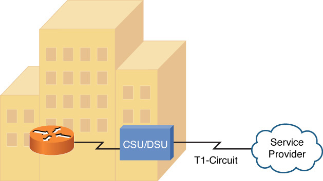
Figure 7-4 CSU/DSU Terminating a Synchronous Circuit
Note
Because a CSU/DSU works with bits, it is classified as a Layer 1 device.
Metro Ethernet
Ethernet ports (using an RJ-45 connecter) are very common and less expensive than specialized serial ports and associated cables. A service provider can provide an Ethernet interface to its customers for their WAN connectivity. The service provider would configure the logical connections (in the provider network) required to connect the customer sites. The technology used in the provider’s network is hidden from the customer, providing what appears to be Ethernet connectivity to each of the customer sites. Actual throughput between sites is controlled by the provider based on the level of service purchased by the customer.
Point-to-Point Protocol
A common Layer 2 protocol used on dedicated leased lines is Point-to-Point Protocol (PPP). PPP has the capability to simultaneously transmit multiple Layer 3 protocols (for example, IP and IPX) through the use of control protocols (CPs). IP, as an example, uses the IP control protocol (IPCP).
Each Layer 3 CP runs an instance of PPP’s Link Control Protocol (LCP). Four primary features offered by LCP include the following:
![]() Multilink interface: PPP’s multilink interface feature allows multiple physical connections to be bonded together into a logical interface. This logical interface allows load balancing across multiple physical interfaces. This is referred to as Multilink PPP.
Multilink interface: PPP’s multilink interface feature allows multiple physical connections to be bonded together into a logical interface. This logical interface allows load balancing across multiple physical interfaces. This is referred to as Multilink PPP.
![]() Looped link detection: A Layer 2 loop (of PPP links) can be detected and prevented.
Looped link detection: A Layer 2 loop (of PPP links) can be detected and prevented.
![]() Error detection: Frames containing errors can be detected and discarded by PPP.
Error detection: Frames containing errors can be detected and discarded by PPP.
![]() Authentication: A device at one end of a PPP link can authenticate the device at the other end of the link. Three approaches to perform PPP authentication are as follows:
Authentication: A device at one end of a PPP link can authenticate the device at the other end of the link. Three approaches to perform PPP authentication are as follows:
![]() Password Authentication Protocol (PAP): PAP performs one-way authentication (a client authenticates with a server), as shown in Figure 7-5. A significant drawback to PPP, other than its unidirectional authentication, is the security vulnerability of its clear text transmission of credentials, which could permit an eavesdropper to learn the authentication credentials being used.
Password Authentication Protocol (PAP): PAP performs one-way authentication (a client authenticates with a server), as shown in Figure 7-5. A significant drawback to PPP, other than its unidirectional authentication, is the security vulnerability of its clear text transmission of credentials, which could permit an eavesdropper to learn the authentication credentials being used.
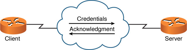
Figure 7-5 PAP Authentication
![]() Challenge-Handshake Authentication Protocol (CHAP): Like PAP, CHAP performs a one-way authentication. However, authentication is performed through a three-way handshake (challenge, response, and acceptance messages) between a server and a client, as shown in Figure 7-6. The three-way handshake allows a client to be authenticated without sending credential information across a network.
Challenge-Handshake Authentication Protocol (CHAP): Like PAP, CHAP performs a one-way authentication. However, authentication is performed through a three-way handshake (challenge, response, and acceptance messages) between a server and a client, as shown in Figure 7-6. The three-way handshake allows a client to be authenticated without sending credential information across a network.
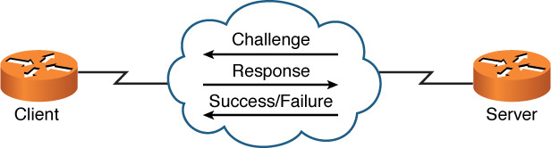
Figure 7-6 CHAP Authentication
![]() Microsoft Challenge-Handshake Authentication Protocol (MS-CHAP): MS-CHAP is a Microsoft-enhanced version of CHAP, offering a collection of additional features, including two-way authentication.
Microsoft Challenge-Handshake Authentication Protocol (MS-CHAP): MS-CHAP is a Microsoft-enhanced version of CHAP, offering a collection of additional features, including two-way authentication.
Note
These PPP features are optional and are not necessarily going to be found in a given PPP connection.
Point-to-Point Protocol over Ethernet
A popular WAN technology (specifically, an Internet access technology) in residences and in businesses is digital subscriber line (DSL). DSL is described later in this section. However, as part of the PPP discussion, note that DSL connections use a variant of PPP called PPP over Ethernet (PPPoE).
As Figure 7-7 illustrates, PPPoE is commonly used between a DSL modem in a home (or business) and a service provider. Specifically, PPPoE encapsulates PPP frames within Ethernet frames. PPP is used to leverage its features, such as authentication. For example, when you set up a DSL modem in your home, you typically have to provide authentication credentials. Although Ethernet does not handle authentication, PPP does. By combining Ethernet with PPP, Ethernet-based devices (for example, PCs) can take advantage of PPP features, such as authentication.
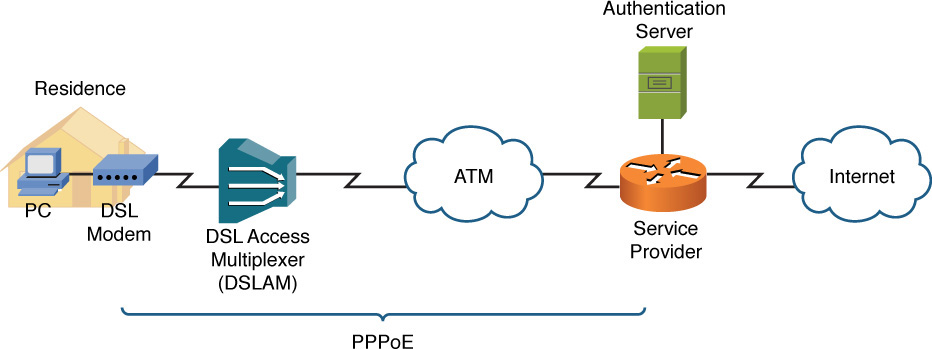
Figure 7-7 PPPoE Sample Topology
Microsoft RRAS
PPP is often the protocol used by Microsoft Routing and Remote Access Server (RRAS), which is a Microsoft Windows Server feature that allows Microsoft Windows clients to remotely access a Microsoft Windows network. Figure 7-8 shows the RRAS configuration window being used to configure a static route.
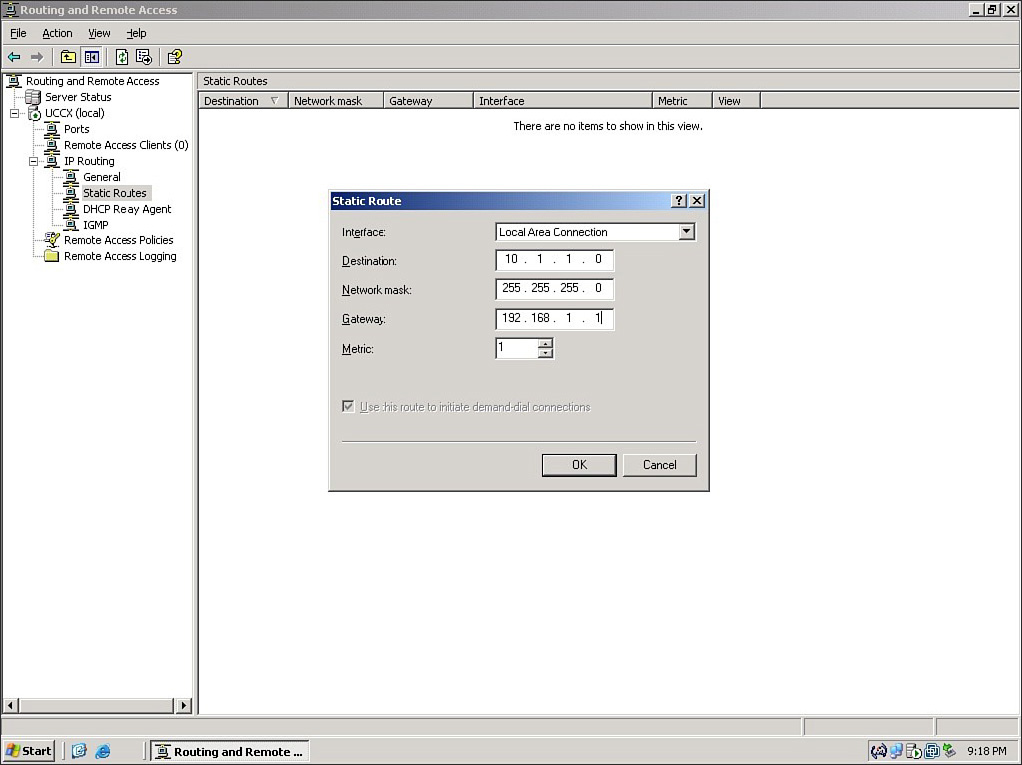
Figure 7-8 Microsoft RRAS
Using PPP along with Microsoft RRAS allows support for PPP features, such as the multilink interface feature. The multilink interface feature could, for example, allow multiple dial-up modem connections to be bonded together into a single logical connection, giving increased bandwidth to a remote Microsoft Windows client.
PPP is not required for Microsoft RRAS, which could alternatively use Serial Line Internet Protocol (SLIP). However, PPP is preferred over SLIP because of PPP’s features (for example, multilink interface and error detection).
Note
Microsoft RRAS was previously known as Microsoft RAS (Remote Access Server).
Note
An alternative to RRAS, where remote clients can become members of a Microsoft Windows network, is remote desktop control. With remote desktop control, a remote computer does not directly become a member of an internal network (for example, a network inside a corporation). Rather, it controls a computer that is already part of an internal network (which could be Microsoft Windows based or based on some other operating system (OS), such as Linux or Mac OS X). With remote desktop control, a remote user can see the screen of the internal computer and control the computer with a keyboard and mouse. One example of a protocol that supports remote desktop control is Independent Computer Architecture (ICA), which is a product of Citrix.
Yet another technology that supports the remote control of a computer’s desktop is virtual network computing (VNC).
Digital Subscriber Line
Commonplace in many residential and small business locations (also known as small office/home office or SOHO locations), digital subscriber line (DSL) is a group of technologies that provide high-speed data transmission over existing telephone wiring. DSL has several variants, which differ in data rates and distance limitations.
Three popular DSL variants include asymmetric DSL (ADSL), symmetric DSL (SDSL), and very high bit-rate DSL (VDSL):
![]() Asymmetric DSL (ADSL): A popular Internet-access solution for residential locations. Figure 7-9 shows a sample ADSL topology. Note that ADSL allows an existing analog telephone to share the same line used for data for simultaneous transmission of voice and data.
Asymmetric DSL (ADSL): A popular Internet-access solution for residential locations. Figure 7-9 shows a sample ADSL topology. Note that ADSL allows an existing analog telephone to share the same line used for data for simultaneous transmission of voice and data.
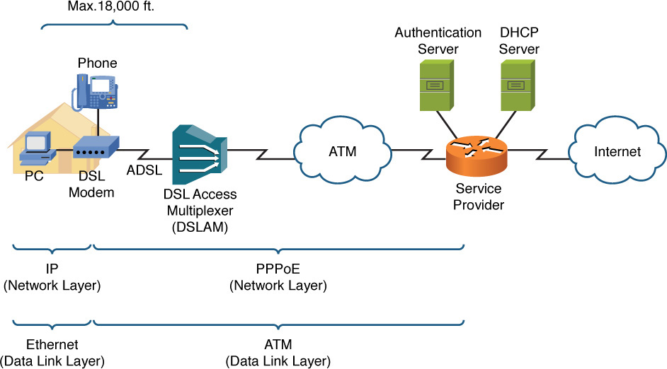
Figure 7-9 ADSL Sample Topology
Also notice in Figure 7-9 that the maximum distance from a DSL modem to a DSL access multiplexer (DSLAM) is 18,000 ft. This limitation stems from a procedure telephone companies have used for decades to change the impedance of telephone lines.
Here is a brief history: If wires in a telephone cable run side-by-side for several thousand feet, capacitance builds up in the line (which can cause echo). To counteract this capacitance, after 18,000 ft. of cable, telephone companies insert a load coil, which adds inductance to the line. Electrically speaking, inductance is the opposite of capacitance. So, by adding a load coil, much of the built-up capacitance in a telephone cable is reduced. However, ADSL signals cannot cross a load coil, thus the 18,000 ft. distance limitation for ADSL.
Figure 7-9 also shows how a telephone line leaving a residence terminates on a DSLAM. A DSLAM acts as an aggregation point for multiple connections, and it connects via an ATM network back to a service provider’s router. The service provider authenticates user credentials, provided via PPPoE, using an authentication server. Also, the service provider has a DHCP server to hand out IP address information to end-user devices (for example, a PC or a wireless router connected to a DSL modem).
The term asymmetric in asymmetric DSL implies the upstream and downstream speeds can be different. Typically, downstream speeds are greater than upstream speeds in an ADSL connection.
The theoretical maximum downstream speed for an ADSL connection is 8 Mbps, and the maximum upstream speed is 1.544 Mbps (the speed of a T1 circuit).
![]() Symmetric DSL (SDSL): Whereas ADSL has asymmetric (unequal) upstream and downstream speeds, by definition, SDSL has symmetric (equal) upstream and downstream speeds. Another distinction between ADSL and SDSL is that SDSL does not allow simultaneous voice and data on the same phone line. Therefore, SDSL is less popular in residential installations because an additional phone line is required for data. Although service providers vary, a typical maximum upstream/downstream data rate for an SDSL connection is 1.168 Mbps. Also, SDSL connections are usually limited to a maximum distance of 12,000 ft. between a DSL modem and its DSLAM.
Symmetric DSL (SDSL): Whereas ADSL has asymmetric (unequal) upstream and downstream speeds, by definition, SDSL has symmetric (equal) upstream and downstream speeds. Another distinction between ADSL and SDSL is that SDSL does not allow simultaneous voice and data on the same phone line. Therefore, SDSL is less popular in residential installations because an additional phone line is required for data. Although service providers vary, a typical maximum upstream/downstream data rate for an SDSL connection is 1.168 Mbps. Also, SDSL connections are usually limited to a maximum distance of 12,000 ft. between a DSL modem and its DSLAM.
![]() Very High Bit-Rate DSL (VDSL): VDSL boasts a much higher bandwidth capacity than ADSL or SDSL, with a common downstream limit of 52 Mbps and a limit of 12 Mbps for upstream traffic.
Very High Bit-Rate DSL (VDSL): VDSL boasts a much higher bandwidth capacity than ADSL or SDSL, with a common downstream limit of 52 Mbps and a limit of 12 Mbps for upstream traffic.
VDSL’s distance limitation is 4000 ft. of telephone cable between a cable modem and a DSLAM. This constraint might seem too stringent for many potential VDSL subscribers, based on their proximity to their closest telephone central office (CO). However, service providers and telephone companies offering VDSL service often extend their fiber-optic network into their surrounding communities. This allows VDSL gateways to be located in multiple communities. The 4000 ft. limitation then becomes a distance limitation between a DSL modem and the nearest VDSL gateway, thus increasing the number of potential VDSL subscribers.
Cable Modem
Cable television companies have a well-established and wide-reaching infrastructure for television programming. This infrastructure might contain both coaxial and fiber-optic cabling. Such an infrastructure is called a hybrid fiber-coax (HFC) distribution network. These networks can designate specific frequency ranges for upstream and downstream data transmission. The device located in a residence (or a business) that can receive and transmit in those data frequency ranges is known as a cable modem, as illustrated in Figure 7-10.
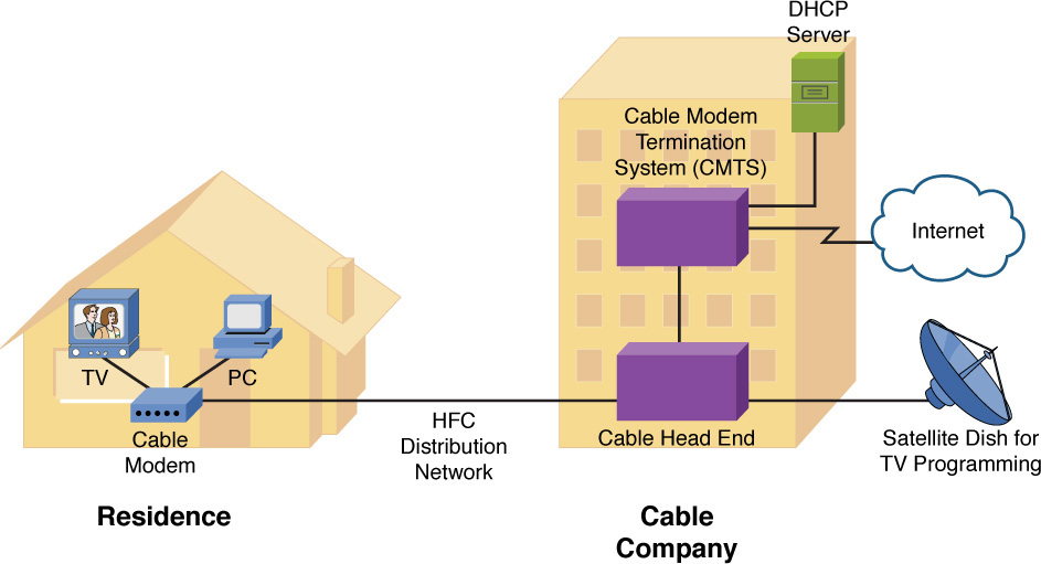
Figure 7-10 Cable Modem Sample Topology
The frequency ranges typically allocated for upstream and downstream data are as follows:
![]() Upstream data frequencies: 5 MHz to 42 MHz
Upstream data frequencies: 5 MHz to 42 MHz
![]() Downstream data frequencies: 50 MHz to 860 MHz
Downstream data frequencies: 50 MHz to 860 MHz
Although the theoretical maximum upstream/downstream bandwidth limits are greater (and are dependent on the HFC distribution network in use), most upstream speeds are limited to 2 Mbps, with downstream speeds limited to 10 Mbps. As HFC distribution networks continue to evolve, greater bandwidth capacities will be available.
The frequencies dedicated to data transmission are specified by a Data-Over-Cable Service Interface Specification (DOCSIS) version. Although DOCSIS is an international standard, European countries use their own set of frequency ranges, their own standard known as Euro-DOCSIS.
Synchronous Optical Network
Synchronous Optical Network (SONET) is a Layer 1 technology that uses fiber-optic cabling as its media. Because SONET is a Layer 1 technology, it can be used to transport various Layer 2 encapsulation types, such as Asynchronous Transfer Mode (ATM). Also, because SONET uses fiber-optic cabling, it offers high data rates, typically in the 155-Mbps to 10-Gbps range, and long-distance limitations, typically in the 20 km to 250 km range. Optical Carrier transmission rates, such as OC3 (close to 155 Mbps) and OC12 (close to 622 Mbps), are examples of specifications for digital signal transmission bandwidth.
Note
The term SONET is often used synonymously with the term Synchronous Digital Hierarchy (SDH), which is another fiber-optic multiplexing standard. Although these standards are similar, SONET is usually seen in North America, whereas SDH has greater worldwide popularity.
A SONET network can vary in its physical topology. For example, devices can connect as many as 16 other devices in a linear fashion (similar to a bus topology) or in a ring topology. A metropolitan-area network (MAN), as depicted in Figure 7-11, often uses a ring topology. The ring might circumnavigate a large metropolitan area. Sites within that MAN could then connect to the nearest point on the SONET ring.
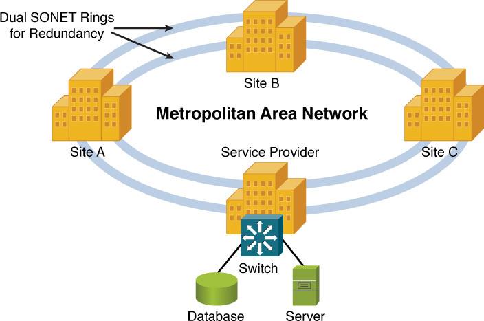
Figure 7-11 SONET Sample Topology
Note
A SONET network uses a single wavelength of light, along with time-division multiplexing (TDM), to support multiple data flows on a single fiber. This approach differs from dense wavelength-division multiplexing (DWDM), which is another high-speed optical network commonly used in MANs. DWDM uses as many as 32 light wavelengths on a single fiber, where each wavelength can support as many as 160 simultaneous transmissions using more than eight active wavelengths per fiber. Coarse wavelength-division multiplexing (CWDM) uses fewer than eight active wavelengths per fiber.
Note
Another optical WAN technology to be aware of is passive optical network (PON), which allows a single fiber cable to service as many as 128 subscribers. This is made possible via unpowered (that is, passive) optical splitters.
Satellite
Many rural locations lack the option of connecting to an IP WAN or to the Internet via physical media (for example, a DSL modem or a broadband cable modem connection). For such locations, a satellite WAN connection, as shown in Figure 7-12, might be an option.
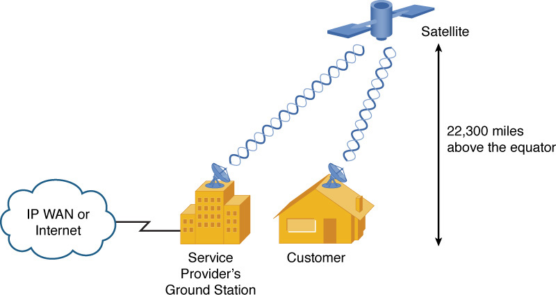
Figure 7-12 Satellite WAN Sample Topology
Most satellites used for WAN connectivity are in orbit above the earth’s equator, about 22,300 miles high. Therefore, if a customer in North America, for example, had a clear view of the southern sky, she would be able to install a satellite dish and establish a line-of-sight communication path with the orbiting satellite.
The satellite would then relay transmissions back and forth between the customer’s site and the service provider’s ground station. The ground station could then provide connectivity, via physical media, to an IP WAN or to the Internet.
Two significant design considerations include the following:
![]() Delay: Radio waves travel at the speed of light, which is 186,000 miles per second, or 3 * 108 meters per second. This speed is specifically the speed of light (and radio waves) in a vacuum; however, for the purposes of this discussion, assume these commonly known values, even though, technically, the speed of light (and radio waves) is a bit slower when traveling through air, as opposed to traveling through a vacuum. Although these are fast speeds, consider the distance between a customer and the satellite. If a customer were located 2,000 miles north of the equator, the approximate distance between the customer site and the satellite could be calculated using the Pythagorean Theorem: d2=20002 + 22,3002. Solving the equation for d, which is the distance between the customer and the satellite, yields a result of approximately 22,390 miles.
Delay: Radio waves travel at the speed of light, which is 186,000 miles per second, or 3 * 108 meters per second. This speed is specifically the speed of light (and radio waves) in a vacuum; however, for the purposes of this discussion, assume these commonly known values, even though, technically, the speed of light (and radio waves) is a bit slower when traveling through air, as opposed to traveling through a vacuum. Although these are fast speeds, consider the distance between a customer and the satellite. If a customer were located 2,000 miles north of the equator, the approximate distance between the customer site and the satellite could be calculated using the Pythagorean Theorem: d2=20002 + 22,3002. Solving the equation for d, which is the distance between the customer and the satellite, yields a result of approximately 22,390 miles.
A transmission from a customer to a destination on the Internet (or IP WAN) would have to travel from the customer to the satellite, from the satellite to the ground station, and then out to the Internet (or IP WAN). The propagation delay alone introduced by bouncing a signal off of the satellite is approximately 241 ms (that is, (22,390 * 2) / 186,000 = .241 seconds = 241 ms). And to that, you have to add other delay components, such as processing delay (by the satellite and other networking devices), making the one-way delay greater than one-fourth of a second, and therefore the round-trip delay greater than one-half of a second. Such delays are not conducive to latency-sensitive applications, such as Voice over IP (VoIP).
![]() Sensitivity to weather conditions: Because communication between a customer’s satellite dish and an orbiting satellite must travel through the earth’s atmosphere, weather conditions can impede communications. For example, if a thunderstorm is in the vicinity of the customer location, that customer might temporarily lose connectivity with her satellite.
Sensitivity to weather conditions: Because communication between a customer’s satellite dish and an orbiting satellite must travel through the earth’s atmosphere, weather conditions can impede communications. For example, if a thunderstorm is in the vicinity of the customer location, that customer might temporarily lose connectivity with her satellite.
Based on these design considerations, even though satellite WAN technology offers tremendous flexibility in terms of geographical location, more terrestrial-based solutions are usually preferred.
Plain Old Telephone Service
The Public Switched Telephone Network (PSTN) is composed of multiple telephone carriers from around the world. An end-user location (for example, a home or business) gets to the PSTN by connecting to its local telephone company, known as a local exchange carrier (LEC). Analog connections (both voice and data connections) using the PSTN are referred to as plain old telephone service (POTS) connections.
With the PSTN as we know it today, you can place a telephone call to just about anywhere in the world from just about anywhere in the world. Although the bandwidth available on the PSTN is limited, the PSTN is such an expansive network, it is more likely to be available in a given location that other wired WAN solutions. So, the benefit of availability has the trade-off of performance.
A POTS connection can be used to access the Internet (or an IP WAN) by connecting a computer to a modem with a serial cable (using a DB-9 [9 pin] or DB-25 [25 pin] RS232/EIA232 serial port, USB with adapter or using a computer with an internal modem), connecting the modem to a POTS phone line, and dialing in to a service provider. The service provider can then connect to the Internet (or an IP WAN), as shown in Figure 7-13.
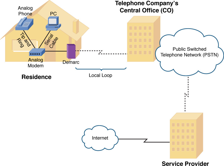
Figure 7-13 Dial-Up Modem Sample Topology
As previously stated, the performance of a POTS connection (using a dial-up modem) is limited. Although modems are rated as 56-Kbps modems, in the United States and Canada, a modem’s upstream data rate is limited to 48.0 Kbps, and its downstream data rate is limited to 53.3 Kbps. These limits are imposed not based on a technical limitation, but based on regulations from these countries’ communications commissions.
Table 7-2 offers a collection of common terms used when working with POTS connections, for both voice and data.
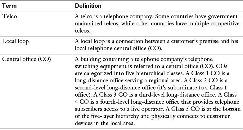
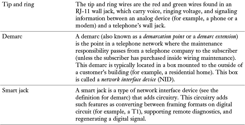
Table 7-2 Common POTS Terms
Integrated Services Digital Network
Integrated Services Digital Network (ISDN) is a digital telephony technology that supports multiple 64-Kbps channels (known as bearer channels [B channels]) on a single connection. ISDN was popular back in the 1980s and was used to connect private branch exchanges (PBXs), which are telephone switches owned by and operated by a company, to a CO. ISDN has the capability to carry voice, video, or data over its B channels. ISDN also offers a robust set of signaling protocols: Q.921 for Layer 2 signaling and Q.931 for Layer 3 signaling. These signaling protocols run on a separate channel in an ISDN circuit (known as the delta channel, data channel, or D channel).
ISDN circuits are classified as either a basic rate interface (BRI) circuit or a primary rate interface (PRI) circuit:
![]() BRI: A BRI circuit contains two 64-Kbps B channels and one 16-Kbps D channel. Although such a circuit can carry two simultaneous voice conversations, the B channels can be logically bonded into a single VC (using the multilink interface feature of PPP as discussed earlier in this chapter) to offer a 128-Kbps data path.
BRI: A BRI circuit contains two 64-Kbps B channels and one 16-Kbps D channel. Although such a circuit can carry two simultaneous voice conversations, the B channels can be logically bonded into a single VC (using the multilink interface feature of PPP as discussed earlier in this chapter) to offer a 128-Kbps data path.
![]() PRI: A PRI circuit is an ISDN circuit built on a T1 or E1 circuit. Recall that a T1 circuit has 24 channels. Therefore, if a PRI circuit is built on a T1 circuit, the ISDN PRI circuit has 23 B channels and 1 64-Kbps D channel. The 24th channel in the T1 circuit is used as the ISDN D channel (the channel used to carry the Q.921 and Q.931 signaling protocols, which are used to set up, maintain, and tear down connections).
PRI: A PRI circuit is an ISDN circuit built on a T1 or E1 circuit. Recall that a T1 circuit has 24 channels. Therefore, if a PRI circuit is built on a T1 circuit, the ISDN PRI circuit has 23 B channels and 1 64-Kbps D channel. The 24th channel in the T1 circuit is used as the ISDN D channel (the channel used to carry the Q.921 and Q.931 signaling protocols, which are used to set up, maintain, and tear down connections).
Also, recall that an E1 circuit has 32 channels, with the first channel being reserved for framing and synchronization and the seventeenth channel being served for signaling. Therefore, an ISDN PRI circuit built on an E1 circuit has 30 B channels and one D channel, which is the seventeenth channel.
Figure 7-14 depicts the constituent elements of an ISDN network.
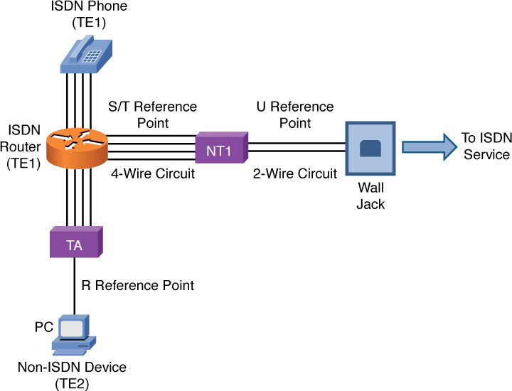
Figure 7-14 ISDN Sample Topology
Some ISDN circuits are four-wire circuits, and some are two-wire. Also, some devices in an ISDN network might not natively be ISDN devices, or they might need to connect to a four-wire ISDN circuit or a two-wire ISDN circuit. As a result of all these variables, an ISDN network, as pictured in Figure 7-14, categorizes various reference points in the network and various elements in the network. Table 7-3 presents some definitions of these reference points and elements.
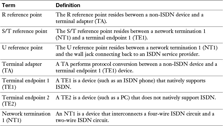
Table 7-3 ISDN Network Reference Points and Elements
Frame Relay
Although it is starting to wane in popularity because of the proliferation of technologies such as cable modems and DSL connections, for many years Frame Relay was the WAN technology of choice for many companies. Frame Relay offers widespread availability and relatively low cost compared to leased lines.
Figure 7-15 shows a sample Frame Relay topology. Frame Relay sites are interconnected using virtual circuits (VCs). So, a single router interface can have multiple VCs. For example, in Figure 7-15, notice that the New York router has two VCs (as indicated by the dashed lines) emanating from a single interface. One VC is destined for the Austin router, and the other VC is destined for the Orlando router. These VCs could be point-to-point circuits, where the VC between New York and Austin belongs to the same IP subnet, and the VC between New York and Orlando belongs to a separate subnet. Alternatively, the connection from New York to Austin and Orlando could be a point-to-multipoint connection, where all routers belong to the same subnet.
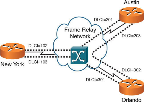
Figure 7-15 Frame Relay Sample Topology
Frame Relay is a Layer 2 technology, and a router uses locally significant identifiers for each VC. These identifiers are called data-link connection identifiers (DLCIs). Because DLCIs are locally significant, DLCIs at the different ends of a VC do not need to match (although they could). For example, note the VC that interconnects New York with Orlando. From the perspective of the New York router, the VC is denoted with a DLCI of 103. However, from the perspective of the Orlando router, the same VC is referenced with a DLCI of 301.
If a VC is always connected, it is considered to be a permanent virtual circuit (PVC). However, some VCs can be brought up on an as-needed basis, and they are referred to as switched virtual circuits (SVCs).
Unlike a dedicated leased line, Frame Relay shares a service provider’s bandwidth with other customers of its service provider. Therefore, subscribers might purchase an SLA (previously described) to guarantee a minimum level of service. In SLA terms, a minimum bandwidth guarantee is called a committed information rate (CIR).
During times of congestion, a service provider might need a sender to reduce his transmission rate below its CIR. A service provider can ask a sender to reduce his rate by setting the backward explicit congestion notification(BECN) bit in the Frame Relay header of a frame destined for the sender that needs to slow down. If the sender is configured to respond to BECN bits, it can reduce its transmission rate by as much as 25 percent per timing interval (which is 125 ms by default). Both CIR and BECN configurations are considered elements of Frame Relay Traffic Shaping (FRTS). A device that does packet shaping is referred to as a packet shaper.
Another bit to be aware of in a Frame Relay header is the discard eligible (DE) bit. Recall that a CIR is a minimum bandwidth guarantee for a service provider’s customer. However, if the service is not congested, a customer might be able to temporarily transmit at a higher rate. However, frames sent in excess of the CIR have the DE bit in their header set. Then, if the Frame Relay service provider experiences congestion, it might first drop those frames marked with a DE bit.
Asynchronous Transfer Mode
Like Frame Relay, Asynchronous Transfer Mode (ATM) is a Layer 2 WAN technology that operates using the concept of PVCs and SVCs. However, ATM uses fixed-length cells as its protocol data unit (PDU), as opposed to the variable frames used by Frame Relay.
As shown in Figure 7-16, an ATM cell contains a 48-byte payload and a 5-byte header. Table 7-4 describes the fields of an ATM header.
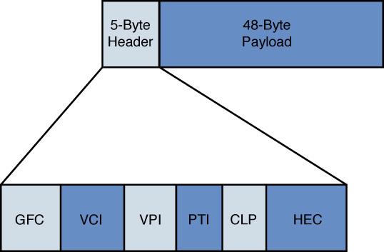
Figure 7-16 ATM Cell Structure
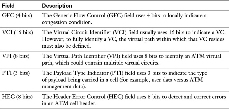
Table 7-4 ATM Header Fields
An ATM cell’s 48-byte payload size resulted from a compromise between the wishes of different countries as an international standard for ATM was being developed. Some countries, such as France and Japan, wanted a 32-byte payload size because smaller payload sizes worked well for voice transmission. However, other countries, including the United States, wanted a 64-byte payload size because they felt such a size would better support the transmission of both voice and data. In the end, the compromise was to use the average of 32 bytes and 64 bytes (that is, 48 bytes).
Although ATM uses VCs to send voice, data, and video, those VCs are not identified with DLCIs. Rather, ATM uses a pair of numbers to identify a VC. One of the numbers represents the identifier of an ATM virtual path. A single virtual path can contain multiple virtual circuits, as shown in Figure 7-17.
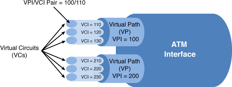
Figure 7-17 ATM Virtual Circuits
Also note in Figure 7-17 that a virtual path is labeled with a virtual path identifier (VPI), and a virtual circuit is labeled with a virtual circuit identifier (VCI). Therefore, an ATM VC can be identified with a VPI/VCI pair of numbers. For example, 100/110 can be used to represent a VC with a VPI of 100 and a VCI of 110.
Figure 7-18 provides an example of an ATM network topology. Notice that interconnections between ATM switches and ATM endpoints are called user-network interfaces (UNI), while interconnections between ATM switches are called network-node interfaces (NNIs).
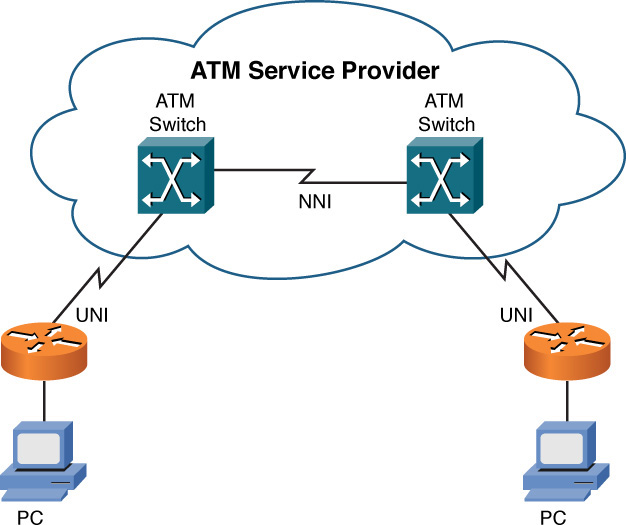
Figure 7-18 ATM Sample Topology
Multiprotocol Label Switching
Multiprotocol Label Switching (MPLS) is growing in popularity as a WAN technology used by service providers. This growth in popularity is due in part to MPLS’s capability to support multiple protocols on the same network—for example, an MPLS network can accommodate users connecting via Frame Relay or ATM on the same MPLS backbone—and MPLS’s capability to perform traffic engineering (which allows traffic to be dynamically routed within an MPLS cloud based on current load conditions of specific links and availability of alternate paths).
MPLS inserts a 32-bit header between Layer 2 and Layer 3 headers. Because this header is shimmed between the Layer 2 and Layer 3 headers, it is sometimes referred to as a shim header. Also, because the MPLS header resides between the Layer 2 and Layer 3 headers, MPLS is considered to be a Layer 2 1/2 technology.
The 32-bit header contains a 20-bit label. This label is used to make forwarding decisions within an MPLS cloud. Therefore, the process of routing MPLS frames through an MPLS cloud is commonly referred to as label switching.
Figure 7-19 shows a sample MPLS network. Table 7-5 defines the various MPLS network elements shown in the figure.
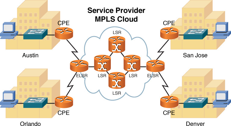
Figure 7-19 MPLS Sample Topology
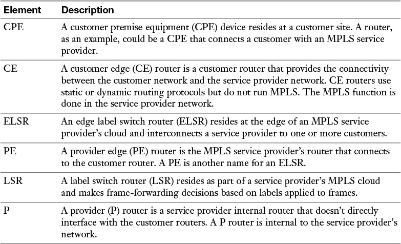
Table 7-5 MPLS Network Elements
An MPLS frame does not maintain the same label throughout the MPLS cloud. Rather, an LSR receives a frame, examines the label on the frame, makes a forwarding decision based on the label, places a new label on the frame, and forwards the frame to the next LSR. This process of label switching is more efficient than routing based on Layer 3 IP addresses. The customer using a provider’s network and the MPLS transport across that network is not normally aware of the details of the exact MPLS forwarding that is done by the service provider.
Overlay Networks
In today’s environments, when virtually every device has connectivity to the Internet, using the basic connectivity of the Internet can also provide wide-area network (WAN) solutions. An example of this is establishing connectivity to the Internet and then building a virtual private network (VPN) between a computer or device on one part of the Internet and a computer or device on another part of the Internet. This is an example of an “overlay” network because the VPN is overlaid on top of another network (in this case the Internet). The benefit of a virtual private network is that authentication and encryption can be done so that anyone on the Internet who may happen to see packets associated with the VPN will not be able to decrypt or understand them without the correct keys, which keeps the VPN content confidential.
For a small company that didn’t want to purchase explicit WAN connectivity between two or more sites, they could simply purchase Internet connectivity and build site-to-site VPNs or remote-access VPNs for their WAN connectivity. We discuss VPNs again in Chapter 12, “Network Security.”
Real-World Case Study
Acme Inc. has its headquarters in a building where multiple service providers are offering high-speed serial and Ethernet-based connectivity options. The company has decided that for the connectivity between the headquarters and the two branch offices, it will use a service provider that is using MPLS-based services. The MPLS connectivity will be delivered to the customer’s CE routers as Ethernet connections. This same service provider will be providing the Internet access, as well, for all three locations. For fault tolerance, the company decided to also purchase Internet access using a serial HDLC connection with a second service provider. In the event the primary service provider fails, the headquarters and two branch office sites will connect to each other using site-to-site VPNs and the Internet as the backbone network for the VPN.
If either of the branch offices loses all connectivity to the Internet (and to the service providers and PLS network), the router at each branch office will be connected to the PSTN so that in a worst-case scenario dial-up connectivity will be established to those routers for management purposes. The dial-up connectivity over the public telephone network would use PPP encapsulation and CHAP authentication.
Remote workers who need to access either the branch or the headquarter locations can do so by using their computer and a VPN connection going to the router or firewall at the site they want to connect to. To enable this, the remote workers would need connectivity to the Internet, which could be through DSL, cable modem, dial-up, or a wireless service provider network that is available to the remote worker, such as a cell phone company that provides data services.
Summary
The main topics covered in this chapter are the following:
![]() This chapter identified the three categories of WAN connections: dedicated leased lines, circuit-switched connections, and packet-switched connections.
This chapter identified the three categories of WAN connections: dedicated leased lines, circuit-switched connections, and packet-switched connections.
![]() Data rates of various WAN technologies were contrasted.
Data rates of various WAN technologies were contrasted.
![]() Various types of WAN media were identified. These types could be categorized as either physical media (including unshielded twisted pair (UTP), coaxial cable, fiber-optic cable, and electric power lines) or wireless technologies (including cellular phone, satellite, WiMAX, HSPA+, and radio technologies).
Various types of WAN media were identified. These types could be categorized as either physical media (including unshielded twisted pair (UTP), coaxial cable, fiber-optic cable, and electric power lines) or wireless technologies (including cellular phone, satellite, WiMAX, HSPA+, and radio technologies).
![]() The basic theory and operation of various WAN technologies were discussed, including dedicated leased line, digital subscriber line (DSL), cable modem, Synchronous Optical Network (SONET), satellite, plain old telephone service (POTS), Integrated Services Digital Network (ISDN), Frame Relay, Asynchronous Transfer Mode (ATM), and Multiprotocol Label Switching (MPLS).
The basic theory and operation of various WAN technologies were discussed, including dedicated leased line, digital subscriber line (DSL), cable modem, Synchronous Optical Network (SONET), satellite, plain old telephone service (POTS), Integrated Services Digital Network (ISDN), Frame Relay, Asynchronous Transfer Mode (ATM), and Multiprotocol Label Switching (MPLS).
Exam Preparation Tasks
Review All the Key Topics
Review the most important topics from inside the chapter, noted with the Key Topic icon in the outer margin of the page. Table 7-6 lists these key topics and the page numbers where each is found.
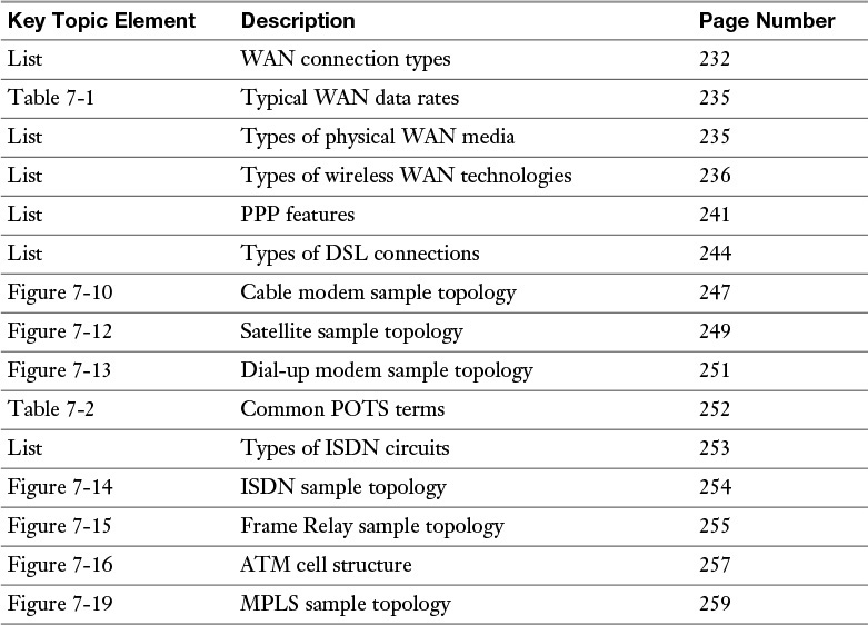
Table 7-6 Key Topics for Chapter 7
Complete Tables and Lists from Memory
Print a copy of Appendix D, “Memory Tables” (found on the DVD), or at least the section for this chapter, and complete the tables and lists from memory. Appendix E, “Memory Table Answer Key,” also on the DVD, includes the completed tables and lists so you can check your work.
Define Key Terms
Define the following key terms from this chapter, and check your answers in the Glossary:
dedicated leased line
circuit-switched connection
packet-switched connection
optical carrier
T1
E1
T3
E3
channel service unit/data service unit (CSU/DSU)
Point-to-Point Protocol (PPP)
Password Authentication Protocol (PAP)
Challenge-Handshake Authentication Protocol (CHAP)
Microsoft Challenge-Handshake Authentication Protocol (MS-CHAP)
Point-to-Point Protocol over Ethernet (PPPoE)
Microsoft Routing and Remote Access Server (RRAS)
digital subscriber line (DSL)
cable modem
Synchronous Optical Network (SONET)
satellite (WAN technology)
Public Switched Telephone Network (PSTN)
plain old telephone service (POTS)
telco
local loop
central office (CO)
tip and ring
demarc
Integrated Services Digital Network (ISDN)
basic rate interface (BRI)
primary rate interface (PRI)
Frame Relay
Asynchronous Transfer Mode (ATM)
Multiprotocol Label Switching (MPLS)
customer premise equipment (CPE)
edge label switch router (ELSR)
label switch router (LSR)
Review Questions
The answers to these review questions are in Appendix A, “Answers to Review Questions.”
1. ISDN is considered to be what type of WAN connection?
a. Dedicated leased line
b. Circuit-switched connection
c. Packet-switched connection
d. Cell-switched connection
2. What is the data rate of an OC-3 connection?
a. 51.84 Mbps
b. 622 Mbps
c. 155.52 Mbps
d. 159.25 Gbps
3. Which of the following WAN technologies commonly use unshielded twisted pair (UTP)? (Choose three.)
a. Cable modem
b. ISDN
c. DSL modem
d. POTS dial-up modem
4. How many channels on an E1 circuit are available for voice, video, or data?
a. 23
b. 24
c. 30
d. 32
5. Which PPP authentication method provides one-way authentication and sends credentials in clear text?
a. WEP
b. MS-CHAP
c. PAP
d. CHAP
6. What DSL variant has a distance limitation of 18,000 ft. between a DSL modem and its DSLAM?
a. HDSL
b. ADSL
c. SDSL
d. VDSL
7. What kind of network is used by many cable companies to service their cable modems and contains both fiber-optic and coaxial cabling?
a. Head-end
b. DOCSIS
c. Composite
d. HFC
8. What locally significant identifier is used by a Frame Relay network to reference a virtual circuit?
a. VPI/VCI
b. DLCI
c. TEI
d. MAC
9. How big is the payload portion of an ATM cell?
a. 5 bytes
b. 48 bytes
c. 53 bytes
d. 64 bytes
10. What is the size of an MPLS header?
a. 4 bits
b. 8 bits
c. 16 bits
d. 32 bits
All materials on the site are licensed Creative Commons Attribution-Sharealike 3.0 Unported CC BY-SA 3.0 & GNU Free Documentation License (GFDL)
If you are the copyright holder of any material contained on our site and intend to remove it, please contact our site administrator for approval.
© 2016-2026 All site design rights belong to S.Y.A.