IPv6 Address Planning (2015)
Part II. Design
Chapter 7. Creating an IPv6 Addressing Plan
Introduction
In this chapter, we’ll take advantage of the topics we learned in Chapters 4 through 6 to walk through building from scratch a couple of sample IPv6 address plans for a (thank $DEITY) fictional company.
We’ll learn effective entry points into our address plan design that depend on whether we want to focus first on the part of our plan within a site or the part of the plan between sites.
Along the way, we’ll explore in depth methods for mapping the network topology into the address plan — how, thanks to the typically large size of an IPv6 address allocation, subnets identifying function and location can be derived from the available bits (bits that were in short supply in IPv4).
Finally, we’ll look at some of the address planning considerations for network topologies that extend the traditional enterprise network in the form of data centers, cloud deployments, and sensor networks.
Meet Strangelove Solutions, LLC
Strangelove Solutions LLC is a boutique software and engineering firm specializing in doomsday scenario and global catastrophic risk modeling, as well as deluxe mineshaft estates, for the discerning (and well-heeled) doomsday prepper.
They have a number of offices in North America, including their headquarters campus in Damascus, Arkansas, and sales offices in Faro, North Carolina and Yuba City, California (Figure 7-1).
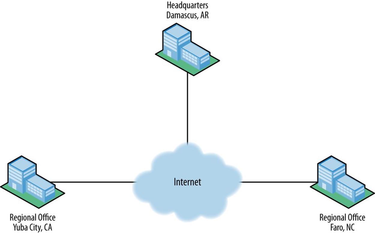
Figure 7-1. Strangelove Solutions inter-site topology
The headquarters campus also includes a data center (Figure 7-2).
The design of the network is fairly typical for an enterprise and includes the following modules:
§ Edge
§ Campus
§ Data center
§ Lab
§ Infrastructure
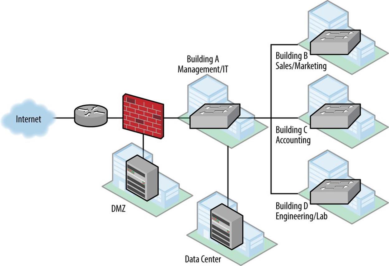
Figure 7-2. Strangelove Solutions intra-site topology
Edge Network
The enterprise edge is located in building A and consists of a head-end router with a single WAN link from their ISP. Behind that, a firewall has segments to the DMZ and to the campus network.
Segments or elements configured in the edge network include:
§ Internet connectivity (WAN to ISP)
§ Firewall
§ IDS
§ DMZ
§ Corporate DNS, email, web
§ VPN for remote access
Campus Network
The campus network consists of a modified campus access-distribution configuration: a distribution switch connects to the data center and has fiber runs to switches in buildings B, C, and D, and terminates VLANs and layer 3 for them. Building A houses the management and IT departments with around 200 employees total. It also houses the data center. Buildings B, C, and D each have around 50 employees.
The campus network incorporates several VLANs including:
§ Wired data
§ Wireless
§ Internal
§ Guest (spans the HQ site)
§ VoIP
Lab Network
The lab in building D is used for research and software validation and is operated by engineering. Layer 3/VLAN termination is provided by a distribution switch in that building’s primary wiring closet.
The lab network includes:
§ Virtual environments
§ Sensor test networks
Data Center Network
The data center network uses a hybrid design that includes both a fairly typical collapsed core with top-of-rack switches to servers, along with a small SDN proof-of-concept network.
The data center network includes:
§ Storage network
§ Private cloud
§ SDN components
Infrastructure
As with our inter-site design, device numbering and network management comprise functions that span the headquarters site. They include such elements as:
§ Loopback and management interfaces
§ Point-to-point interfaces
§ Out-of-band networks for lab and data center
§ Guest wireless networks
Where to Start: Topology or Plan?
So now that we have a better picture of the network we need to design an address plan for, where do we begin?
Recall from Chapter 5 that, at their most essential, addressing plans in IPv6 are primarily about defining and assigning blocks of subnets based on the structure of the network or the organization.
This fundamental concept provides at least two possible entry points into creating a design for our (thankfully) fictional company:[99]
§ Derive an IPv6 address plan structure from an existing topology
§ Or map a generic address plan structure onto a topology
Another way to think of this is that the former is more of a bottom-up approach, while the latter is a top-down one.
Keep in mind that it’s perfectly acceptable and actually quite common to use both methods interchangeably at different stages of the address plan design. Initially, however, it’s helpful to pick one or the other to get started.
And, of course, over time the address plan and actual topology will interact and influence each other. For instance, using IP address management practices and tools to track subnet utilization will result in additional IPv6 space being allocated (and already-allocated space being reclaimed). This process will inevitably impact network planning and deployment, which will result in changes to the network topology.[100]
Mapping Topology to Plan Between Sites
Which of these two entry points should we use for our sample design? Well in Chapter 5, we made a distinction between inter-site and intra-site architecture — something we’ve reflected in Strangelove LLC’s simple network diagrams shown previously.
Since there’s only one instance of inter-site topology, it might make the most sense to derive the initial part of our IPv6 address plan structure from that first entry point. In other words, we’ll use the number of sites Strangelove LLC has to create an inter-site address plan structure.
Recall also from Chapter 5 that a site is a logical concept. It’s an entity within our network topology that has well-defined and well-understood boundaries. These boundaries are most typically based on location, but could also be based on function (i.e., an application or group of users that share a common security or QoS requirement).
The actual bit boundary of the /48 is where all of the subnets at a particular location would be rolled up (i.e., aggregated or summarized) into that single prefix.
In a similar fashion, the bit boundary of the /48 can be used to enforce QoS or security policy for a function, as we’ve described previously.
With three sites (in this case, and as is typical, the sites are locations), Strangelove LLC would appear to need at least 3 /48s.
But keep in mind we’ve also got a data center at HQ. Strangelove’s somewhat eccentric (i.e., insane) management team has decided that the risk of nuclear catastrophe is greater at their Damascus, Arkansas headquarters. They’ve tentatively decided to move the existing data center to one of their regional offices. For maximum portability, the data center should get its own /48.
Strangelove LLC is also designing a private cloud service (aka, “the Mushroom Cloud”) that they hope to integrate with a secure public cloud offering in the near future. It seems prudent to allocate an additional /48 for whatever the cloud architecture ends up looking like.
Finally, connectivity between sites is currently provided by MPLS VPN, and the associated inter-site infrastructure will get a /48 as well.
Here’s a summary of Strangelove LLC’s inter-site topology for which /48 allocations are suggested:
§ HQ
§ Regional office (Faro)
§ Regional office (Yuba City)
§ Data-center
§ Cloud architecture
§ Infrastructure
So even though there are only three main sites, a total of 6 /48s will be needed. And while 3 bits would apparently provide enough (i.e., 8) /48s, you’re hopefully on-board with the best practice of allocation along nibble boundaries from our earlier reading.
Thus, a /44 would be the minimum allocation size we should assume when deriving our inter-site address plan structure from our actual topology.
At this point, Strangelove LLC hasn’t requested a PI allocation from the RIR, so for the purposes of planning and illustration, we’ll use a /44 from the documentation range.[101] Figure 7-3 shows this placeholder /44 prefix along with the allocations described above.
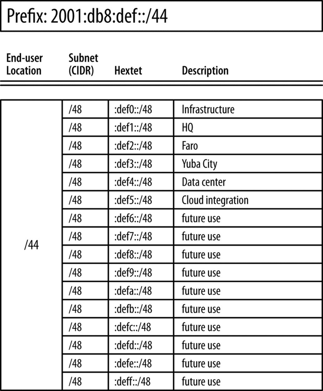
Figure 7-3. Strangelove LLC inter-site allocations
Mapping Plan to Topology Within Sites
As for the second design entry point (mapping a generic address plan structure onto a topology), such an approach seems to be more applicable where there are multiple, similar topologies, and we want to use our address plan to try to make overall address management and operations between sites as consistent as possible.
So what might a generic address plan structure look like? Well, based on our fundamental address plan design concept, it needn’t be much more initially complicated than groups of subnets hierarchically arranged.
As stated, we’ll focus on the inter-site portion of the plan, i.e., the 16 bits between a /48 and /64. To keep things as simple as possible, we’ll use one of the subnetting hierarchies from Figure 4-1.
The first of those subnetting hierarchies gives us the most predictable allocation of the available address space as it allocates sequentially on the next available nibble boundary: e.g., /48, /52, /56, /60, and /64.
Or to put it another way:
§ Each /48 provides 16 /52s
§ Each /52 provides 16 /56s
§ Each /56 provides 16 /60s
§ Each /60 provides 16 /64s
Figure 7-4 shows the relationships between the allocations.
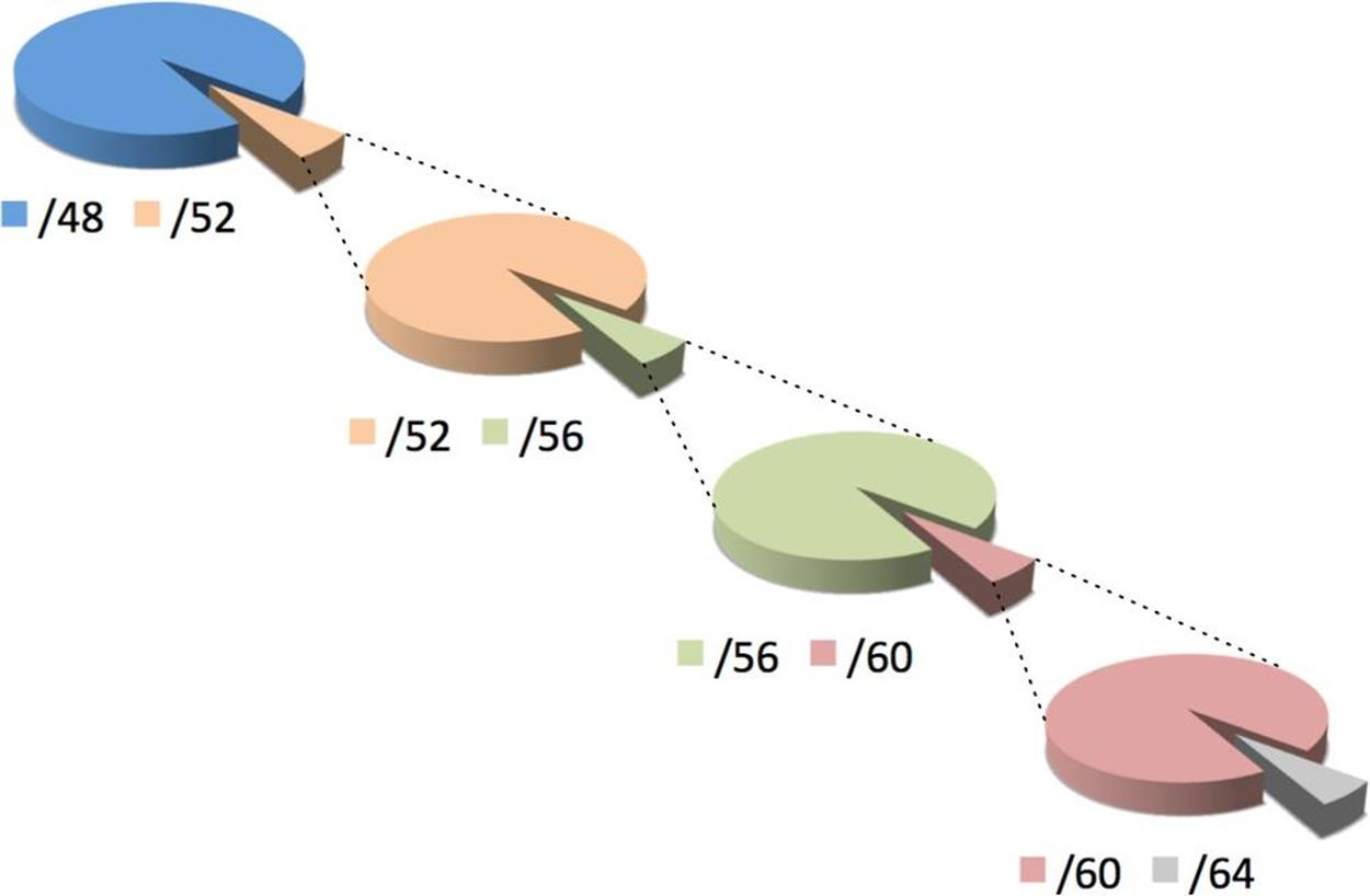
Figure 7-4. /48 to /64 in sequential nibbles
With no more than 16 elements or descriptors per level of hierarchy, this choice is also the most manageably (or, perhaps, least unmanageably) displayed as a worksheet excerpt. (Figure 7-5).
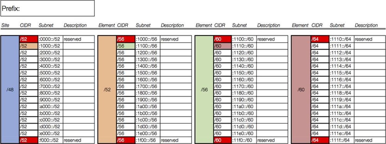
Figure 7-5. Address Plan Worksheet excerpt
To begin to populate this worksheet using our example organization, we’ll refer back to Figure 7-2 to help determine the appropriate hierarchy levels.
It makes the most sense to assign the first level of hierarchy to the primary modules within the site. (The sole exception would be the data center for which we have already set aside a /48.)
We reserve the 0/52 subnet and assign 2001:db8:def1:1000::/52 to the campus network. The edge, infrastructure, and lab networks get the next three subnets: i.e., :2000::/52, :3000::/52, and :4000::/52 (Figure 7-6).
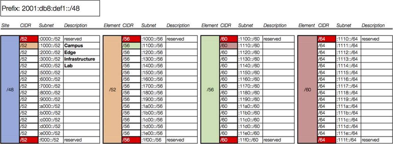
Figure 7-6. Intra-site worksheet, level 1
As the color coding suggests, the next column of our worksheet corresponds only to the campus prefix we just assigned in column 1 (2001:db8:def1:1000::/52). The campus network comprises (among other attributes) four buildings. For level 2 of the intra-site hierarchy, each building will receive a /56 (Figure 7-7).
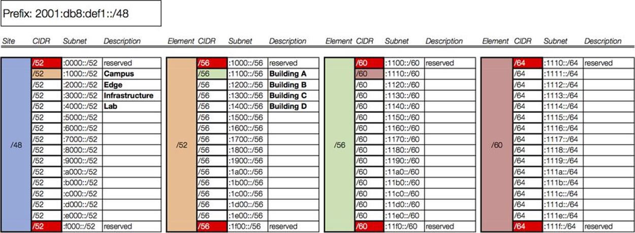
Figure 7-7. Intra-site worksheet, level 2
We again select the first subnet (corresponding to building A) to populate the next column in our worksheet. Building A has two organizational functions: Management and IT. Each will receive a /60 (Figure 7-8).
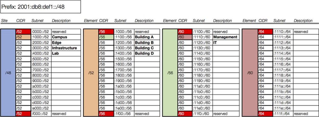
Figure 7-8. Intra-site worksheet, level 3
In the final column, each /60 is subnetted to provide /64s for interface assignments, corresponding to VLANs in this case (Figure 7-9).
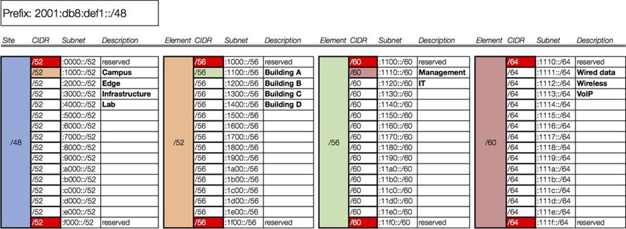
Figure 7-9. Intra-site worksheet, level 4
We’ve only included one subsequent level of hierarchy and requisite column for the campus /52: i.e., Campus → Building A → Management/IT → Wired, Wireless, VoIP.
In a fully documented plan, we would need a column for each subsequent level of hierarchy. For example, the /56 we designated for building B would have 16 /60s, corresponding to the organizational roles associated with it, i.e., marketing and sales. Each of these /60s would in turn have 16 /64s available for VLAN definition.
As you can observe, even given the extra tidiness that nibble boundaries provide, we’re still confronted with the challenge of how to manageably represent our available and used allocations (something we’ll cover in more detail in the next chapter).
ZERO SUBNETS HAVE A PROBLEM
The first subnet of a group of IPv6 subnets is always enumerated with a 0. In the instance where the prefix contains consecutive zeros that allow for prefix zero compression, presentation inconsistency results.
For instance, as we saw in Chapter 4 (under “Visualizing Hierarchy”), numerating /52 subnets for 2001:db8:1::/48 gives us:
2001:db8:1::/52 (or, expanded for clarity, 2001:db8:1:0000::/52)
2001:db8:1:1000::/52
2001:db8:1:2000::/52
2001:db8:1:3000::/52
...
2001:db8:1:F000::/52
As evident, by the rules of zero compression, the first subnet can legally be expressed in its (pardon my French) smooshed form.
This can potentially confuse and cause problems for operational personnel, especially if they’re not paying close attention to the CIDR notation, since the number of characters in the prefixes for both the parent /48 and the first /52 of the enumerated group is the same:
2001:db8:1::/48
2001:db8:1::/52
One way to prevent this confusion is to avoid assigning the zero subnet:
2001:db8:1::/52 (reserved)
2001:db8:1:1000::/52 (first assigned)
2001:db8:1:2000::/52
2001:db8:1:3000::/52
...
2001:db8:1:F000::/52
Where we adhere to the nibble boundary, this approach has the added benefit of having the first subnet we assign to an element be numbered 1. Since this conforms to the way normals typically enumerate elements (e.g., 1,2,3,…n), it can provide for less confusion and more consistent operations and fault isolation.
Function and Location Assignment Revisited
We’ve now spent a fair amount of time observing how IPv6 subnets can be grouped together according to some standard concepts and practices. These steps allow us to arrange and assign subnets in ways that are logical and consistent with our network topology. We’re able to reliably do this because IPv6 provides us with enough bits in any typical allocation (especially as compared with IPv4).
Another advantage of this logical and consistent structure is that we can map it on to our network topology in a way that best facilitates administration and operation of the network by enabling one or both of the following:
1. Prefix summarization
2. Security or QoS policy enforcement
As we discussed briefly in Chapter 5, this is usually accomplished by assigning our groups of prefixes to locations or functions within the network topology.
A location typically corresponds to a part of the network whose address prefixes will be summarized at the boundary of that part. This promotes operational efficiency in providing a summarized prefix in the routing table, potentially reducing convergence time and preserving router resources.
SITE VERSUS LOCATION
At this point, you may be asking yourself “Well just what the heck is the difference between a site and a location anyway?” It’s a fair question because the distinction can be subtle (or nonexistent).
The simplest answer is that while a site is a /48 (well, almost always a /48 — see below) and always on a nibble boundary, locations can correspond to any size prefix in the network.
And to really confuse things, recall that a site doesn’t have to be a /48. Since a site is ultimately defined according to the addressing and operational needs of the requesting organization, it could be larger or smaller. As mentioned, some ISPs are defining a site as a home user’s cable modem and assigning it a /56. (Will 256 /64s will be sufficient addressing for a single home network? Time will tell!)
If that’s too abstract for your liking, it’s perfectly appropriate to think of a site as an enterprise campus with a building on that campus as a location.[102]
TIP
Even where routing resources are abundant and convergence time is not an issue, mapping location into the address plan provides administrative logic that helps facilitate operations. As we saw with our loopback address example, even addresses within a single subnet can be logically encoded with location information that can help operational personnel locate and remediate resources on the network.
IPv6 subnet assignments according to function may correspond to roles that have different security or QoS requirements and that may span locations. This allows administrators to more easily define, deploy, and modify security or QoS policy. As a result, the overall number of ACL entries can be potentially reduced and ACL maintenance can be easier to accomplish.
CAUTION
Because there is no subnet mask in IPv6, any ultra-granular ACLs we might have configured in IPv4 (e.g., using wildcard subnet masks to identify groups of addresses for special QoS or security policy treatment) don’t have an equivalent in IPv6. On the other hand, in IPv6, there should never be a shortage of unique subnets to deploy for special QoS or security policy treatment.
Because the typically large scale of an IPv6 allocation allows for potentially many levels of hierarchy, either location or function may be mapped into any given hierarchy level within an IPv6 address plan (something that we’ll show an example of below). But regardless of which is selected and used, the significance of the choice can be encoded into the address prefix in all cases. And as we learned in Chapter 5, defining subnets exclusively on nibble boundaries increases the legibility of our prefixes in relation to their function or location assignments.
FLATLAND
As the effect of Moore’s law drives processor and memory costs ever lower, network devices subsequently become more efficient at holding and processing network state information, especially for typical LAN-sized networks. As a result, routing convergence and packet-switching performance can be accomplished with less network segmentation at layer 3.
The resulting trend is toward flatter networks, and fewer segments means fewer subnets and routes. Thus, for all but very large enterprise sites, it’s unlikely that you’ll be doing much intra-site aggregation or summarization. This fact would seem to favor assigning functional significance to our IPv6 address prefixes over location significance.
Enterprise IT is working to increase business agility by deploying (and integrating with) technologies like virtualization, cloud, and SDN. Support of mobile devices and applications has increased manyfold. These in turn require more sophisticated internal security models that deemphasize a simple perimeter model, leading to a more confederated (and typically more effective) security policy.
As a result, functional IPv6 prefix assignments may offer better integration into, and support of, this new environment.
Assigning Function and Location
Now let’s take a look at the prefixes we’ve allocated for Strangelove LLC’s network and observe what function or location significance they might receive.
We’ve already determined that each of Strangelove LLC’s sites will receive a /48 (along with the /48s set aside for infrastructure, data center, and cloud integration). The entries in Figure 7-3 illustrate how the third hextet of the prefix provides location significance.
These /48s can be summarized to a /44 for their BGP announcement to upstream provider(s):[103]
2001:db8:def0::/48
2001:db8:def1::/48
2001:db8:def2::/48
. . .
2001:db8:deff::/48
2001:db8:def::/44
Of course, since we’re using fewer than 8 /48s in our original address plan, we could summarize to a non-nibble boundary, creating two summary prefixes:
2001:db8:def0::/45
2001:db8:def8::/45
This could be useful if Strangelove Solutions LLC executes its plan for acquiring Pulowski Preservation Services, designers and manufacturers of “quality” personal fallout shelters.[104] Having eight unused, contiguous /48s (summarized into a contiguous /45) would be really handy if the merger leads to any obligatory renumbering of any newly acquired network infrastructure.
The further subnetting and assignment we’ve done within each site will still permit those subnets to be summarized at the site level, potentially reducing routing convergence time, as well as keeping the number of routes between sites to a minimum.
Next, we’ll drill down on the headquarters site, i.e., 2001:db8:def1::/48. Referring to Figure 7-9, we can observe how mapping location and function significance to the levels of hierarchy we’ve defined for Strangelove LLC’s network may be accomplished quite easily (and legibly thanks to our adherence to the nibble boundary).
Our first level of hierarchy includes the following network modules:
§ Campus
§ Edge
§ Infrastructure
§ Lab
Based on the fact that these modules represent both separate layer 3 network locations, as well as unique roles, they could be assigned either functional or locational significance. And though the modules are equally sized and will be summarized to the next level, they also have differing security requirements in relation to each other and the Internet. As a result, the ability to more easily determine security policy and simplify ACL entries may be facilitated by assigning functional significance to this group of subnets.
In general, which one we assign depends on whether we’d need to be able to summarize a given group of prefixes up to the next level of hierarchy or whether any particular subnet might span multiple locations and require a more elaborate security policy and ACL configuration at the primary hierarchy level.
As a result of assigning functional significance to our first hierarchy level, we’ll represent as Fs (for function) the first four bits (and the first hex character) of the fourth hextet.
2001:db8:def1:[FFFF XXXX XXXX XXXX]::/52
Thus, the individual /52s for each module could be assigned across multiple locations within the site while still allowing for a centralized firewalling.
Our second level of network hierarchy in our plan includes the campus buildings:
§ Building A
§ Building B
§ Building C
§ Building D
These buildings all share a /56 assignment and though not independently administered, the networks for these buildings (and any buildings added later) can be summarized up to the /52. As a result, we’ll represent the second four bits as Ls (for location).
2001:db8:def1:[FFFF LLLL XXXX XXXX]::/56
Additional layers of hierarchy can be assigned function or location significance in the same fashion.
CAUTION
Where functional significance is assigned at the top layer of hierarchy in order to facilitate security policy, it is usually not possible to assign location significance in order to aggregate subnets at a lower layer of hierarchy.
Addressing the Data Center
While the network topology for the campus module is a pretty straightforward corporate LAN, the data center architecture for Strangelove LLC (along with data center architecture in general) is a little different. As a result, we’ll need to come up with a plan that makes sense for it.
Let’s take a closer look at the data center topology (Figure 7-10).
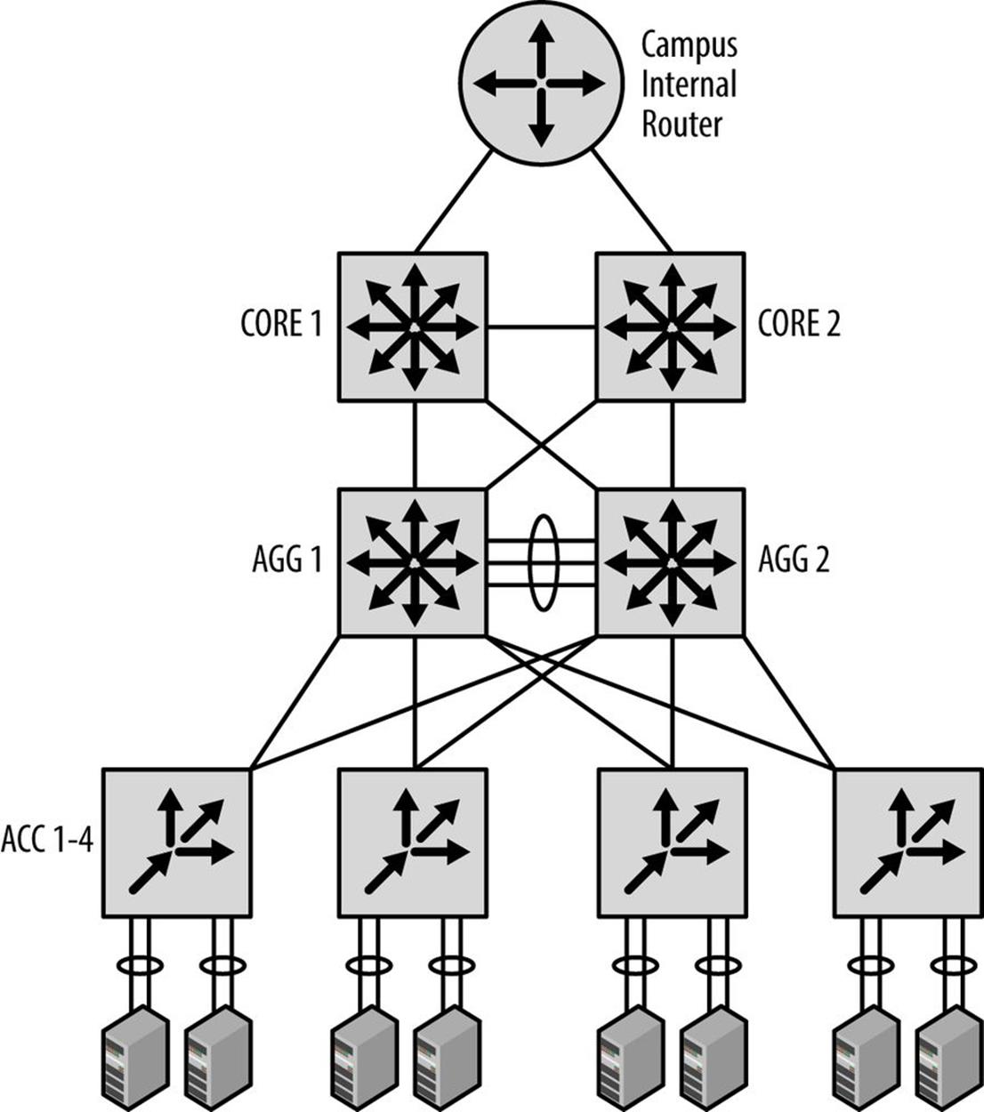
Figure 7-10. Strangelove LLC data center: topology and address plan
Strangelove LLC has what it thinks is a pretty standard data center architecture.
The campus core router feeds in to two core switches trunked together. Two aggregation layer switches are fully meshed with the core switches. This aggregation layer terminates connections from top-of-rack switches.
The top-of-rack switches connect up to servers via NIC-teaming. Functions provided by the servers include web, storage, and database. All of the links are 10GbE.
We’ve allocated 2001:db8:def4::/48 specifically for the data center, so as with our overall campus address plan, we’ll focus on assigning the 16 bits between the /48 site-level boundary and the /64 interface-level boundary.
The topology within the data center has a few characteristics that will help guide our address planning for it.
The first of these is that the topology is relatively flat from a layer 3 perspective. Since we’ll need little if any summarization below the core level, it makes sense to reserve whatever number of initial bits we’ll need for functional significance.
As for the number of bits we’ll need for our first level of hierarchy, the data center currently supports three primary applications (i.e., web, storage, and database services), but may add additional services in the future.
In addition, each service cluster is separated at layer 3 to support a possible multi-tenancy architecture. The number of clusters per service has been projected not to exceed 24 for the foreseeable future.
So to determine the number of bits needed for our first level of hierarchy, let’s multiply the total number of existing and planned services requiring support times the number of existing and planned service clusters.
Services(e+p) x Clusters(e+p) = 8 x 24 = 192
Solving for 2x = 192, where x = number of bits needed, we easily see that x is between 7 and 8 (since 27 = 128 and 28 = 256). Since we can’t split bits, we’ll go ahead and round up to 8.
So 8 bits required for our first level of hierarchy for the data center /48 would provide 256 /56s (which gives us 32 clusters per service).
Since we’re not worried about summarization below the /48 level and have selected functional assignment, we could assign /56s per service per cluster in any order. While this would require the least amount of planning (and eventually consume the highest possible quantity of available subnets), it might also make any security or QoS policy ACLs longer than necessary (e.g., a single entry per /56 for a maximum of 256 entries).
However, if we group our /56s according to their services, we can make our plan easier to administer.
For example, since we know we may have up to 24 clusters per service, it makes sense to leave enough bits between services to support sequential assignment of clusters per service.
Again, since 24 isn’t on a power-of-2 network boundary (much less a nibble boundary), we’ll need to round up to 32.
Since we know we have three existing services (with plans for no more than five additional services for a total of eight), we could sparsely allocate the first 3 bits required to define these services. This would ensure that any services we define later would have as many as 32 /56 subnets to sequentially number into.[105]
Recall that sparse allocation is equivalent to bitwise counting up of the left-most bits for the group of bits being allocated; in this case, the next 3 bits of 2001:db8:def4::/48. Table 7-1 has three columns: the first showing the group number; the second, the bitwise counting up of the first 3 bits (to provide eight groups total); the third, showing the hexadecimal equivalent.
Table 7-1. Sparse allocation of service groups
|
Group # |
Bits |
Hex |
|
8 |
1110XXXX |
:e000::/56 |
|
1 |
0000XXXX |
:0000::/56 |
|
2 |
0010XXXX |
:2000::/56 |
|
3 |
0100XXXX |
:4000::/56 |
|
4 |
0110XXXX |
:6000::/56 |
|
5 |
1000XXXX |
:8000::/56 |
|
6 |
1010XXXX |
:a000::/56 |
|
7 |
1100XXXX |
:c000::/56 |
The /56s in each group can be sequentially assigned.
We’ll use 255 of the 256 /64s per /56 for VLAN assignment within each cluster (again, tossing out the 0 prefix for numbering consistency).
Summary
The purpose of this chapter was to get comfortable with the process of how the IPv6 address planning principles and methods we learned in earlier chapters are applied in order to create an actual IPv6 address plan.
Hopefully, at this point, you’re beginning to see that for all of IPv6 additional complexities, it has many facets, especially those related to address planning, that are actually quite simple, both to learn and apply.
The ultimate goal, of course, is to instill the critical knowledge and confidence necessary to create (or perhaps effectively revise) an IPv6 address plan for your organization.
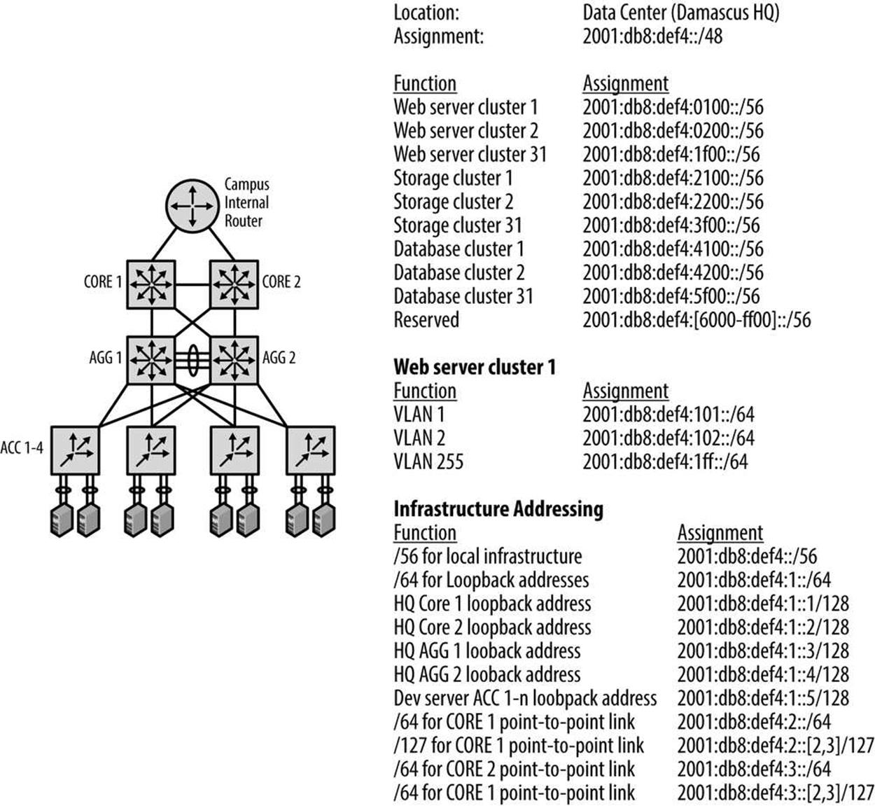
Figure 7-11. Strangelove LLC data center: topology and address plan
[99] Though if you’re bullish on the luxury doomsday prep vertical, I’m not here to judge!
[100] We’ll cover IP address management in more detail in the next chapter.
[101] RFC 3849, IPv6 Address Prefix Reserved for Documentation.
[102] Any floors or departments might derive their subnets from whatever location subnet is assigned. In turn, subnets for functions such as wired data, wireless data, VoIP, printers, sensors, etc. would be derived from the relevant floor or department subnet.
[103] We’ll take a closer look at how BGP routing may effect our IPv6 address plan in Chapter 10.
[104] I think I know what you’re thinking, but Vault-Tec’s market capitalization is simply too large for a minor player like Strangelove Solutions, LLC.
[105] Well, technically 31, as we’ll avoid using the 0 subnet to keep our cluster numbering lined up with the actual prefix number.
All materials on the site are licensed Creative Commons Attribution-Sharealike 3.0 Unported CC BY-SA 3.0 & GNU Free Documentation License (GFDL)
If you are the copyright holder of any material contained on our site and intend to remove it, please contact our site administrator for approval.
© 2016-2026 All site design rights belong to S.Y.A.