Packet Tracer Network Simulator (2014)
Chapter 5. Navigating and Modifying the Physical Workspace
A simulator, as the name says, only logically simulates the required environment. However, Packet Tracer is much more than that. It simulates devices physically too. You've read that a copper Ethernet cable has a range of 100 meters, but have you bothered to try using it? Getting a 100 meter wire and struggling with it is not at all required as we will do just that in this chapter. Do you find the device icons boring? How about spicing things up with your own icons and background images? We will show you all this and more in this chapter.
Creating cities, offices, and wiring closets
So far, we've used the logical workspace to create topologies. The physical workspace makes your logical topology more realistic by giving it a physical dimension. The physical workspace has four environments: Intercity, City, Building, and Wiring closet.
· Intercity: This is the largest environment consisting of cities. Cities, buildings, and wiring closets can be created in this layer using the controls on the toolbar.
· Cities: This layer contains buildings and wiring closets. The default city is named Home City. Cities can be dragged and placed anywhere on the intercity map.
· Buildings: This layer contains wiring closets. The default building is named Corporate Office.
· Wiring closet: This is the final layer that contains devices placed in the logical topology. Its default name is Main Wiring Closet and it doesn't have any specified area.
Moving devices physically
All devices used in the logical workspace are placed in Main Wiring Closet; we'll learn how to move them.
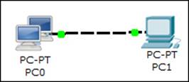
1. Create a topology in the logical workspace with two PCs. Replace their default modules with PT-HOST-NM-1FGE (remember to switch off both the PCs before doing this) because Ethernet has distance restrictions (we'll learn more about this in the following section). Connect both of them with a fiber cable and assign IP addresses.
2. Switch to the physical view, click on the New City button on the yellow toolbar, and rename the newly-created city. In this example, we'll name it Remote City. Open this city and create a new building, and then create a new wiring closet within this building.
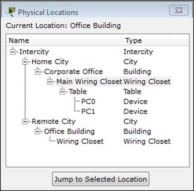
3. Use the NAVIGATION button and navigate to Home City | Corporate Office | Main Wiring Closet. This contains both the PCs we inserted in the logical workspace, as shown in the following screenshot:
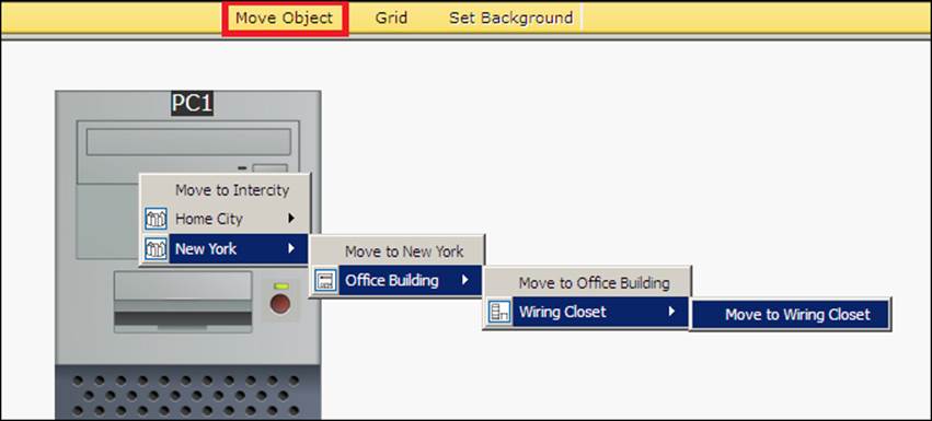
4. Use the Move Object button (or keys Shift + M) and move one of the PCs to Remote City | Office Building | Wiring Closet, as shown in the following screenshot. This can also be done in the navigation box by using the drag-and-drop feature.
5. Navigate to the intercity and you'll find a link between home city and remote city. Now navigate to Remote City | Office Building | Wiring Closet to find the PC we moved.
Moving back to the logical topology, you'll see absolutely no difference in the placement of the PCs. Devices can also be moved to the intercity, cities, and buildings. In these cases, the icon of the device is displayed in the physical environment.
Managing cables and distances
The physical view adds a dimension of distance for wired and wireless devices. This is very useful for working out the placement of wireless devices.
Cable distances
Measuring a cable is as easy as placing the pointer on a cable in the physical view (as shown in the following screenshot):
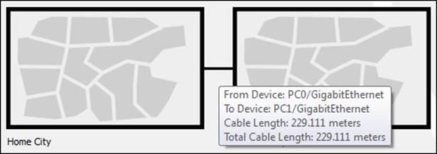
Standard copper Ethernet cables can extend up to a length of 100 meters; let's test this with the physical view:
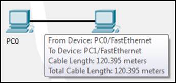
1. Create the same two PC topologies that we used previously (as shown in the following screenshot) but use the copper cable instead of the fiber one.
2. In the physical view, move both the PCs to the intercity by following the instructions in the previous section.
3. Navigate to the intercity and check the distance between them. If the distance is less than 100 meters, move them further apart, until the distance between them is more than 100 meters.
4. Now come back to the logical view and you'll find that the link status of both the PCs is red because the connection came down due to the distance.
5. Delete the link between the PCs and place a Repeater-PT from the hubs section. Connect both the PCs to the repeater with a copper straight-through cable. The link still remains down because this repeater was placed in the main wiring closet (which is still at a larger distance) that is very far from the intercity, as shown in the following screenshot:
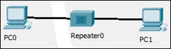
6. Move to the physical view, navigate to the Main Wiring Closet and move the repeater to the intercity. Go to the intercity and place the hub between the two PCs. Now you'll find that the link comes up as the repeater boosts the signal.
Cable manipulation
Let's move to the cable manipulation part of the physical workspace. Once you have a lot of devices, it becomes confusing to see which cable connects to what. Packet Tracer's physical workspace has a feature that allows cables to be color coded.
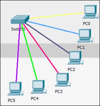
To color-code a cable, click on a wire in the physical view, choose Color Cable from the context menu, and pick a color from the Select Color dialog box. The following screenshot shows cables after they've been color coded:
The physical workspace also has a bend point creation feature that can be used to remove the tangled look of cables. To create a bend point, click on a cable and choose Create bendPoint from the context menu. Any number of bend points can be created on a single link, as shown in the following screenshot:
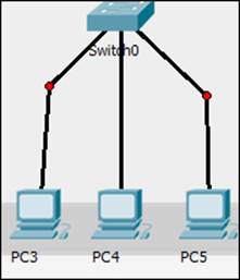
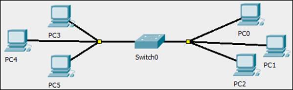
In addition, bend points can also be grouped together to form group points. To create a group point, drag a bend point and place it on another bend point. The red circle changes to a yellow square, as shown in the following screenshot:
To delete a bend point, use the delete tool from the Common Tools bar and click on the bend point. This removes only the bend point; the connection still remains.
To delete a group point, use the same delete tool and click on the group point. A context menu contains options to either ungroup a single bend point or to ungroup all. This removes only group points; the bend points remain as it is.
Customizing icons and backgrounds
Even though Packet Tracer offers its own set of icons for each device, it is also possible to change it with our own icon. To change the icon of a device, click on it and from under the Physical tab click on the Customize Icon in Logical View button. Choose an icon from a location to change it in the logical view as shown in the following screenshot:
If an icon is customized in the physical view, its changes are visible only if it is placed somewhere outside the wiring closet. The backgrounds of both the logical and physical workspaces can also be customized. To change the background of the logical workspace, click on the Set Tiled Background button and choose an image. If the chosen image is smaller than the workspace, you can use the Display Tiled Background Image option.
In the physical workspace, the background can be changed for each of the intercity, city, building, and wiring closets in the same way.
Summary
In this chapter, we've learned about the physical workspace of Packet Tracer. This will help you to discover a lot of new possibilities for using wireless devices. Customizing icons and backgrounds not only improves aesthetics but also helps to differentiate between devices belonging to different organizations. In the next chapter, we will focus more on Cisco networking by explaining IP routing—both static and dynamic. The simulation mode comes very handy here, to see how things work.
All materials on the site are licensed Creative Commons Attribution-Sharealike 3.0 Unported CC BY-SA 3.0 & GNU Free Documentation License (GFDL)
If you are the copyright holder of any material contained on our site and intend to remove it, please contact our site administrator for approval.
© 2016-2026 All site design rights belong to S.Y.A.