Packet Tracer Network Simulator (2014)
Chapter 6. Configuring Routing with the CLI
We have finally reached the important part of networking—routing. Routing allows communication between multiple logical networks. When configuring routing on the command line of Packet Tracer—similar to configuring on physical hardware—you'll find that Packet Tracer offers a GUI to configure static and RIP routing protocols. In addition to this, we'll also see how load balancing works using the simulation mode, which will help you understand things better.
Static routing
Static routing is the no-brainer method for configuring routing even though it requires more work. With Packet Tracer, static routing can be configured using the GUI alone. In this method, we configure a router with a destination and a gateway to reach it. So, each router in a topology should know the means to reach all destinations in the network, which requires manual work. Similarly, if a router is added or removed from the topology, all routers must be manually updated to reflect this.
Static routing with GUI
Even if you do not know Cisco commands, this feature of Packet Tracer comes in handy. For this exercise, we will be using the topology shown in the following screenshot:.
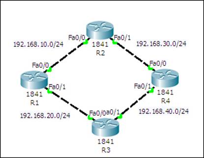
This network has four routers in a ring topology, with no PCs or loopback interfaces. Because we will be using only the GUI here, configuration will be kept to a minimum. The topology can be configured by performing the following steps:
1. Click on a router icon, go to the Config tab, select an interface, and configure the IP address. Make sure that you select the On checkbox in this section to bring the port state up. For this example, we'll be using the following IP addresses:
|
Router |
Interface |
IP Address |
|
R1 |
FastEthernet0/0 |
192.168.10.1 |
|
FastEthernet0/1 |
192.168.20.1 |
|
|
R2 |
FastEthernet0/0 |
192.168.10.2 |
|
FastEthernet0/1 |
192.168.30.1 |
|
|
R3 |
FastEthernet0/0 |
192.168.20.2 |
|
FastEthernet0/1 |
192.168.40.1 |
|
|
R4 |
FastEthernet0/0 |
192.168.30.2 |
|
FastEthernet0/1 |
192.168.40.2 |
2. Under the ROUTING section, click on Static. The following screenshot is displayed:
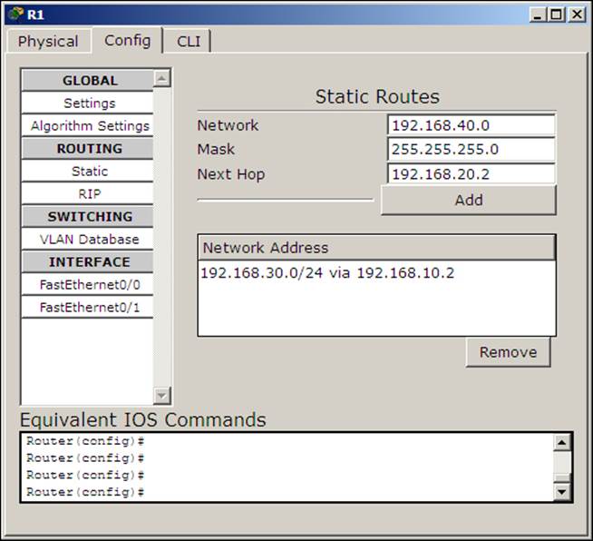
3. The following settings will be used for configuring static routing using the GUI. The concept here is to enter all routes that are not directly connected to a router and a gateway IP that belongs to a network that is directly connected.
|
Device |
Network/Mask |
Next Hop |
|
R1 |
192.168.30.0 / 255.255.255.0 |
192.168.10.2 |
|
192.168.40.0 / 255.255.255.0 |
192.168.20.2 |
|
|
R2 |
192.168.20.0 / 255.255.255.0 |
192.168.10.1 |
|
192.168.40.0 / 255.255.255.0 |
192.168.30.2 |
|
|
R3 |
192.168.10.0 / 255.255.255.0 |
192.168.20.1 |
|
192.168.30.0 / 255.255.255.0 |
192.168.40.2 |
|
|
R4 |
192.168.10.0 / 255.255.255.0 |
192.168.30.1 |
|
192.168.20.0 / 255.255.255.0 |
192.168.40.1 |
4. Now use simple PDU and test the connectivity between all of the routers. Then use the simulation mode to find the route taken by the packets.
5. How about taking a look at the routing table? For this, too, the GUI has an option; click on the inspect icon or press I and select a router. A table containing four routes will appear for each router, as shown in the following screenshot:
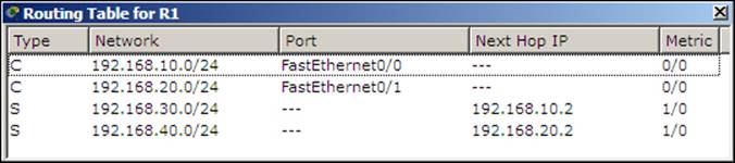
But we configured only two routes, so why four? The extra two routes are the subnets of the directly-connected links.
In this topology, even though there is an alternate route to each network, only one route is used because this is how we have configured it. We'll learn more about having more than one route in the Load Sharing section.
Static routing with the CLI
The configuration and the topology will be same in this section. We'll only see the commands required for one device. The topology can be configured by performing the following steps:
1. Assign IP addresses to the interfaces on each router using the following commands:
2. R1(config)#interface FastEthernet0/0
3. R1(config-if)#ip address 192.168.10.1 255.255.255.0
4. R1(config-if)#no shutdown
5. R1(config-if)#exit
6. R1(config)#interface FastEthernet0/1
7. R1(config-if)#ip address 192.168.20.1 255.255.255.0
8. R1(config-if)#no shutdown
R1(config-if)#exit
9. Configure static routing with the ip route command, using the following syntax:
10.R1(config)#ip route <Destination Prefix> <Destination prefix mask> <Gateway IP>
11. For router R1, the following commands are used:
12.R1(config)#ip route 192.168.30.0 255.255.255.0 192.168.10.2
13.R1(config)#ip route 192.168.40.0 255.255.255.0 192.168.20.2
Use simple PDU to test the connectivity. If you get message indicating a failure, switch to simulation mode and see which router is incorrectly configured.
Dynamic routing protocols
When we learned about static routing we found that a lot of manual configuration was involved and a change to the topology also required manual configuration changes. Dynamic protocols work by advertising routes to each other.
The configuration is the opposite of static routing; here, we enable dynamic routing on the required interfaces. The routing protocol then forms "neighborship" with other routers and sends them the directly-connected routes and other received routes. In this way, all routers exchange updates with one another. When a topology change occurs, those updates are also sent out by routers that learn about this loss of connectivity.
Configuring RIP with the GUI
Packet Tracer offers a GUI to configure a dynamic routing protocol called RIP (Routing Information Protocol). This GUI section is similar to the static routing section. It has only one textbox for entering the network address of the directly connected network.
You may think that the rest of the configuration is similar to the Static configuration, but it isn't. Whereas in the static configuration we entered routes of other routers, in RIP, we enter the network IP addresses of the router's interfaces. By doing this, you are enabling that routing protocol on a particular interface. To configure dynamic routing with the GUI, perform the following steps:
1. Create the same four-router topology we used previously and assign the same IP addresses through the Config tab.
2. Click on RIP—now, configuring this is very easy, with each router requiring only the Network IP of its own interfaces, as shown in the following screenshot:
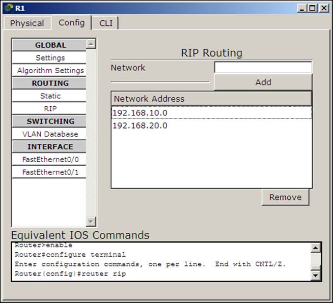
3. Enter the following network IP addresses:
|
Device |
RIP Network |
|
R1 |
192.168.10.0 |
|
192.168.20.0 |
|
|
R2 |
192.168.10.0 |
|
192.168.30.0 |
|
|
R3 |
192.168.20.0 |
|
192.168.40.0 |
|
|
R4 |
192.168.30.0 |
|
192.168.40.0 |
4. Once the topology is configured, use the simple PDU to check for connectivity. Let's check for two indirectly connected routers (R1 and R4 or R2 and R3). Once the connection is successful, let's see how dynamic routing works on topology changes.
5. Use the delete tool and remove either the link between R1 and R2 or the link between R1 and R3. Use the simulation mode and test connectivity with the simple PDU. You'll find that the packet takes the alternate, longer route and succeeds in reaching the destination.
If you have tried step 5 of the static routing topology, the packet would've failed as we did not enter any alternate gateway to each destination network. This is the biggest advantage of using a dynamic routing protocol.
Configuring RIP with the CLI
Let's do the same thing using the CLI tab. The commands are very simple and if you have noticed the Equivalent IOS Commands section under the Config tab, you'll know them already. To configure dynamic routing by using the CLI tab, perform the following steps:
1. Use the same commands used in the Static section to assign IP addresses to the interfaces.
2. Then, from the global configuration mode, enter into the config mode of RIP by issuing the following command:
3. R1(config)#router rip
4. Use the network command, followed by the network IP address. For the device R1, use the following commands:
5. R1(config-router)#network 192.168.10.0
6. R1(config-router)#network 192.168.20.0
7. Configure all the other routers in the same way. Use the simple PDU to test the connectivity.
Now that you know how to configure basic static and dynamic routing, let's move to the routing table.
The Routing table
A routing table lists all of the preferred routes known to a router. It is viewable in two ways, one using the inspect tool of packet tracer and the other using the show ip route Cisco IOS command. With each way, you'll see a table with lots of columns and information. We are about to see what each of these means. Here is a sample output of a command used to show the routing table:
R1>show ip route
C 192.168.10.0/24 is directly connected, FastEthernet0/0
R 192.168.20.0/24 [120/1] via 192.168.10.1, 00:00:18, FastEthernet0/0
C 192.168.30.0/24 is directly connected, FastEthernet0/1
R 192.168.40.0/24 [120/1] via 192.168.30.2, 00:00:08, FastEthernet0/1
The first column denotes the routing protocol. The letter C is for connected and R is for RIP; if you check the routing table after configuring static routing, you'll find the letter S.
The next column is the destination network. After this, comes the administrative distance (AD)—the first number inside the square brackets; this specifies which routing protocol takes priority. The second number in the square brackets, after the slash, is the metricof this route. On RIP, the number of hops to reach a destination is used as the metric. RIP has an AD of 120 and static routing has 1.
So, if a router has two routes for the same destination network via both static routing and RIP, static routing will be used as it has a lower AD.
The IP address after via is the gateway's IP, also know as the next hop IP through which this route is reached. The time clock after that is called the Holddown timer. In any dynamic routing protocol, messages are sent at a certain interval (30 seconds in RIP). Each time a hello message is received, this timer is reset. If no response is received within 180 seconds this route is removed or an alternate route is found.
The final column is the outgoing interface to reach the gateway.
Load sharing
In the topology we have being configuring throughout this chapter, we can find that each router has two paths to reach each destination. So how about seeing how routers use these multiple paths together and load balancing the traffic across them.
Load balancing with RIP
We take RIP first because we do not have to do anything specific for load balancing. If there are multiple paths to reach a network destination with the same metric, RIP automatically load balances them. We will be using an interface type known as loopback to achieve this. A loopback is a virtual interface that behaves like a real interface and takes IP addresses.
We'll use the same topology we've been using throughout this chapter, and just add an extra interface. On router R4, we will add a loopback interface by using the following steps:
1. Unfortunately, it isn't possible to do this with the GUI, so go to the CLI tab of R4 and enter the following commands:
2. R4(config)#interface loopback 0
3. R4(config-if)#ip address 192.168.100.0 255.255.255.0
4. Now on the same router, let's enable this interface for RIP. Go to the RIP config mode and enter the network IP of this interface.
5. R4(config)#router rip
6. R4(router-if)#network 192.168.100.0
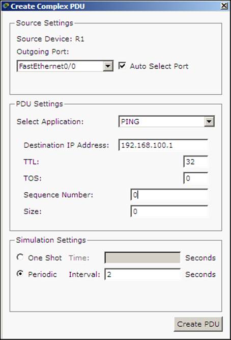
7. That's it, create a complex PDU that is sent every two seconds.
8. Switch over to the simulation mode and you'll find that the first packet takes the R1-R2-R4 route while the second takes the R1-R3-R4 route.
You can also see which routes are load balanced by looking into the following routing table:
Router>show ip route
R 192.168.30.0/24 [120/1] via 192.168.10.2, 00:00:12, FastEthernet0/0
R 192.168.40.0/24 [120/1] via 192.168.20.2, 00:00:14, FastEthernet0/1
R 192.168.100.0/24 [120/2] via 192.168.20.2, 00:00:08, FastEthernet0/1
[120/2] via 192.168.10.2, 00:00:08, FastEthernet0/0
Only the RIP routes are shown here. Note that the route 192.168.100.0/24 has two gateways; this indicates that traffic to this network is load balanced.
Load balancing with static routing
Static routing requires additional configuration for a route to be load balanced. Assign IP addresses to all physical interfaces and also configure loopback interfaces as explained in the RIP section. To configure a load balanced route with static routing, perform the following steps:
1. Go to router R2 and R3 and configure a route to the R4 router's loopback interface by using the following commands:
2. R2(config)#ip route 192.168.100.0 255.255.255.0 192.168.30.2
3. R3(config)#ip route 192.168.100.0 255.255.255.0 192.168.40.2
4. Now for R1, we have to configure two routes to reach 192.168.100.0/24. We need to tell the router that there are two ways to get to the R4 router's loopback. We do this by using the following commands:
5. R1(config)#ip route 192.168.100.0 255.255.255.0 192.168.10.2
6. R1(config)#ip route 192.168.100.0 255.255.255.0 192.168.20.2
7. Use the same complex PDU to see how traffic is load balanced.
After this configuration, if you look at the routing table, you'll find the network 192.168.100.0/24 has two routes, similar to RIP.
Summary
In this chapter, we saw how to configure static and dynamic routing with RIP in Cisco Packet Tracer. By now you will understand the differences between both of them and the pros and cons of each of them. We also saw configuring load balancing with both RIP and static routing.
In the next chapter, we will talk only about a single routing protocol called Border Gateway Protocol (BGP). Although it is also a dynamic routing protocol, it differs to a great extent from other dynamic routing protocols.
All materials on the site are licensed Creative Commons Attribution-Sharealike 3.0 Unported CC BY-SA 3.0 & GNU Free Documentation License (GFDL)
If you are the copyright holder of any material contained on our site and intend to remove it, please contact our site administrator for approval.
© 2016-2025 All site design rights belong to S.Y.A.