Packet Tracer Network Simulator (2014)
Chapter 8. IPv6 on Packet Tracer
IPv4 has 4.3 billion addresses, which may seem mindboggling. However, it took only two decades for it to reach its depletion. IPv6 has come to the rescue in the form of 128-bit addresses. Packet Tracer supports a wide array of IPv6 features. We'll start by learning how to assign IP addresses to different devices and how to configure routing between them. Finally, we'll create a setup that enables IPv6 communication over IPv4 devices.
Assigning IPv6 addresses
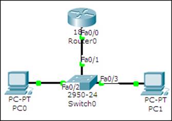
Starting from Packet Trace Version 6, the IP Configuration utility under the Desktop tab of end devices has an option to enter an IPv6 address. Let's begin with a simple topology consisting of two PCs and a router connected to a switch, as shown in the following screenshot:
There are three ways of assigning IPv6 addresses to a device and we'll see each one of them.
Autoconfiguration
Autoconfiguration requires the least amount of configuration but makes it difficult to remember the IPv6 addresses. This method uses the MAC address of the device to create an IPv6 address with the FE80:: prefix. Carry out the following steps to assign IPv6 addresses using Autoconfiguration:
1. Begin by configuring the router. Enter the interface configuration mode and enable IPv6 on the interface.
2. R0(config)#ipv6 unicast-routing
3. R0(config)#interface FastEthernet0/0
4. R0(config-if)#ipv6 enable
5. Next, we will configure a link local address and a global unicast address on this interface. We'll use eui-64 to reduce the configuration.
6. R0(config-if)#ipv6 address autoconfig
7. R0(config-if)#ipv6 add 2000::/64 eui-64
8. R0(config-if)#no shutdown
9. Verify that the interface is up and has two IPv6 addresses.
10.R0>sh ipv6 interface brief
11.FastEthernet0/0 [up/up]
12. FE80::2D0:58FF:FE65:E701
13. 2000::2D0:58FF:FE65:E701
14. These IPv6 addresses may vary when you try them out, as they are based on the MAC address. Enable routing so that this router can be identified as a default gateway.
15.R0(config)#ipv6 unicast-routing
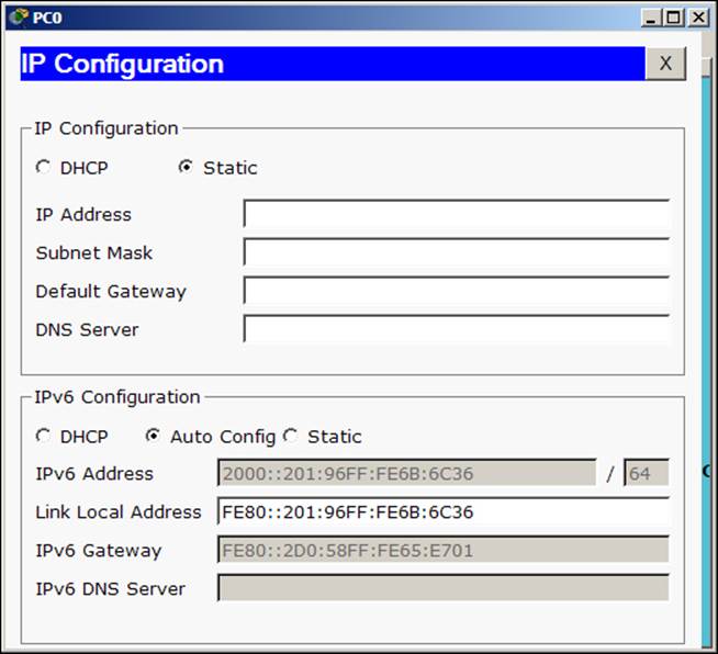
16. The configuration of the router is now done, let's move on to the PCs. Go to the Desktop tab of the PC, open IP Configuration, and under the IPv6 Configuration section, choose Auto Config. The gateway and the PC's IP address will be assigned automatically, as shown in the following screenshot:
17. Use the simple PDU tool to test the connectivity; you'll see ICMPv6 packets moving between the nodes. To view the IPv6 address from the command line of PCs, use the ipv6config command.
Static IPv6
IPv6 addresses can also be assigned statically on all devices. We'll use the same topology for this section too. We'll carry out the following steps to configure IPv6 addresses statically:
1. Begin by configuring a static IPv6 address on the router.
2. R0(config)#interface fastethernet0/0
3. R0(config-if)#ipv6 enable
4. R0(config-if)#ipv6 address 2000::1/64
5. R0(config-if)#no shutdown
6. Go to the Desktop tab of PC, open the IP Configuration utility, and enter an IPv6 address with the same prefix.
7. Now use the simple PDU tool to test the connectivity. Once both the methods work fine, you can have a look at the IPv6 neighbors table. This is similar to the ARP table of IPv4.
8. R0#sh ipv6 neighbor
9. IPv6 Address Age Link-layer Addr State Interface
10.2000::2 0 00E0.A39E.05C4 REACH Fa0/0
11.2000::3 0 0001.43B9.0268 REACH Fa0/0
Now that we have configured IPv6 addresses on a single network, let's configure them on more networks and enable routing between them.
IPv6 static and dynamic routing
Similar to IPv4, IPv6 too supports both static and dynamic routing. Configuration commands for its static routing are similar to IPv4.
Static routing
Modifying the same topology that we used previously, let's add a router, switch, and two PCs to create a separate network, as shown in the following screenshot:
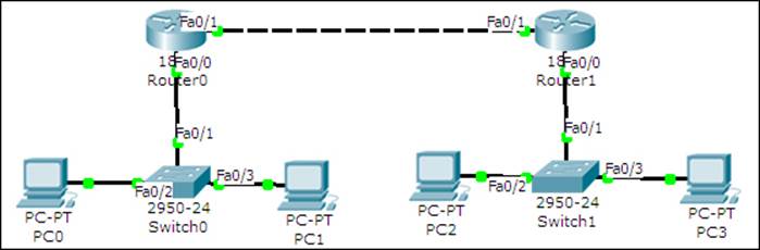
The first network will use addresses starting from 2000:1::/64 and the second network will use addresses starting from 2000:2::/64. The link between both the routers will have IP addresses 2001::10/64 and 2001::20/64.
Here is a table describing the topology:
|
Device |
Interface |
IP address |
|
R1 |
FastEthernet0/0 |
2000:1::1/64 |
|
FastEthernet0/1 |
2001::10/64 |
|
|
PC0 |
FastEthernet |
2000:1::2/64 |
|
PC1 |
FastEthernet |
2000:1::3/64 |
|
R2 |
FastEthernet0/0 |
2000:2::1/64 |
|
FastEthernet0/1 |
2001::20/64 |
|
|
PC2 |
FastEthernet |
2000:2::2/64 |
|
PC3 |
FastEthernet |
2000:2::3/64 |
After the necessary IP addresses and gateways have been assigned, open the CLI tab for the R1 router, and start configuring routing by following the given commands:
R1(config)#ipv6 unicast-routing
R1(config)#ipv6 route 2000:2::/64 2001::20
Next, open the CLI tab for R2 and configure routing on it.
R2(config)#ipv6 unicast-routing
R2(config)#ipv6 route 2000:1::/64 2001::10
Now use the simple PDU tool to test the connectivity. You may also use the tracert command on a PC to see the path a packet takes.
PC>tracert 2000:2::3
Tracing route to 2000:2::3 over a maximum of 30 hops:
1 63 ms 63 ms 47 ms 2000:1::1
2 94 ms 78 ms 94 ms 2001::20
3 156 ms 109 ms 129 ms 2000:2::3
Trace complete.
Dynamic routing
Packet Tracer offers the same dynamic routing protocols for IPv6: RIPv6, EIGRP, and OSPF. We'll be configuring RIPv6 in this section. Note that RIPv6 does not represent RIP Version 6; it is RIP for IPv6 addresses.
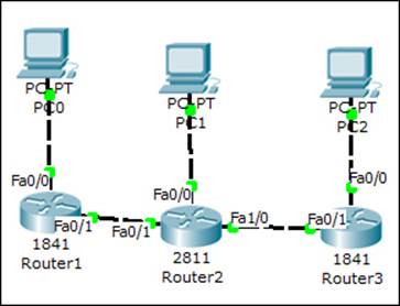
For this exercise, we'll use the topology shown in the following screenshot:
The additional IP assignment details alone are shown in the following table:
|
Device |
Interface |
IPv6 Address |
|
R2 |
FastEthernet1/0 |
2001:1::10/64 |
|
R3 |
FastEthernet0/0 |
2000:3::1/64 |
|
FastEthernet0/1 |
2001:1::20/64 |
|
|
PC2 |
FastEthernet |
2000:3::2/64 |
We'll see how to configure RIP on one router and you can do the same on the others.
R1(config)#interface FastEthernet0/0
R1(config-if)#ipv6 address 2000:1::1/64
R1(config-if)#ipv6 rip Net1 enable
R1(config-if)#ipv6 enable
R1(config-if)#interface FastEthernet0/1
R1(config-if)#ipv6 address 2001::10/64
R1(config-if)#ipv6 rip Net1 enable
R1(config-if)#ipv6 enable
Note that the ipv6 rip command is used to enable RIP on a particular interface. Entering ipv6 rip Net1 enable on the first interface begins the RIPv6 process. The Net1 string can be any name that can be used to name the RIP process. Once configured, use the usual diagnostic tools (ping to simple PDU) to check the connectivity. To view the RIP database, use the following command:
R1#sh ipv6 rip database
RIP process "Net1" local RIB
2000:2::/64, metric 2, installed
FastEthernet0/1/FE80::201:97FF:FE87:E5A9, expires in 173 sec
2000:3::/64, metric 3, installed
FastEthernet0/1/FE80::201:97FF:FE87:E5A9, expires in 173 sec
2001::/64, metric 2
FastEthernet0/1/FE80::201:97FF:FE87:E5A9, expires in 173 sec
2001:1::/64, metric 2, installed
FastEthernet0/1/FE80::201:97FF:FE87:E5A9, expires in 173 sec
RIP process "LINK" local RIB
Trace the route of the packet to see the path it takes.
PC>tracert 2000:3::2
Tracing route to 2000:3::2 over a maximum of 30 hops:
1 31 ms 32 ms 31 ms 2000:1::1
2 50 ms 50 ms 63 ms 2001::20
3 94 ms 94 ms 94 ms 2001:1::20
4 125 ms 109 ms 125 ms 2000:3::2
Trace complete.
Using both IPv4 and IPv6
In this section, we'll see how to make IPv6-only hosts communicate with other IPv6-only hosts through IPv4-only devices. There are several methods for doing this; we'll discuss IPV6 over IPv4 tunneling using Generic Routing Encapsulation (GRE).
The GRE method encapsulates IPv6 packets within IPv4 packets and transports them over the IPv4 network. The receiving device decapsulates the packet and sends only the IPv6 information to the host. For this exercise, we'll use the following topology:
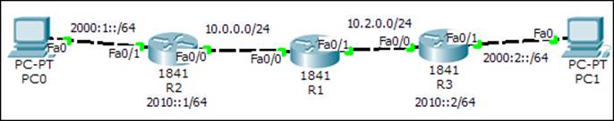
For routing, we will configure EIGRP on IPv4 interfaces for the three routers and static routing on R2 and R3. We will begin by configuring R1, which is the IPv4-only router.
R1(config)#int fa0/0
R1(config-if)#no shutdown
R1(config-if)#ip add 10.0.0.1 255.255.255.0
R1(config)#int fa0/1
R1(config-if)#no shutdown
R1(config-if)#ip add 10.2.0.1 255.255.255.0
R1(config-)#router eigrp 1
R1(config-router)#network 10.0.0.0
Now on the router R2, we will configure IPv4 and IPv6 addresses and routing, respectively.
R2(config)#ipv6 unicast-routing
R2(config)#int fa0/1
R2(config-if)#no shutdown
R2(config-if)#ipv6 add 2000:1::1/64
R2(config)#router eigrp 1
R2(config-router)#network 10.0.0.0 0.0.0.255
Do the same for router R3.
R3(config)#ipv6 unicast-routing
R3(config)#int fa0/1
R3(config-if)#no shutdown
R3(config-if)#ipv6 add 2000:2::1/64
R3(config)#int fa0/0
R3(config-if)#no shutdown
R3(config-if)#ip add 10.2.0.2 255.255.255.0
The only configuration left is the tunnel creation. For router R2, carry out the following list of commands:
R2(config)#int tunnel 0
R2(config-if)#tunnel source f0/0R2(config-if)#tunnel destination 10.2.0.2
R2(config-if)#tunnel mode ipv6ip
R2(config-if)#ipv6 address 2010::1/64
Note that the destination IP is the IPv4 address of interface f0/0 of R3. Configure the other end of the tunnel on router R3
R3(config)#int tunnel 0
R3(config-if)#tunnel source f0/0
R3(config-if)#tunnel destination 10.0.0.2
R3(config-if)#tunnel mode ipv6ip
R3(config-if)#ipv6 address 2010::2/64
The only thing left now is to configure static-IPv6 routes for the prefixes 2000:1::/64 and 2000:2::/64.
R2(config)#ipv6 route 2000:2::/64 2010::2
R3(config)#ipv6 route 2000:1::/64 2010::1
Use the simple PDU tool to check connectivity between PC0 and PC1. Use the tracert command to find the path that the ICMPv6 protocol takes.
PC>tracert 2000:2::2
Tracing route to 2000:2::2 over a maximum of 30 hops:
1 0 ms 0 ms 0 ms 2000:1::1
2 0 ms 0 ms 0 ms 2010::2
3 0 ms 0 ms 0 ms 2000:2::2
Trace complete.
This shows IPv6 packets going through the tunnel.
Summary
In this chapter, we learned how to use IPv6 with Packet Tracer. We saw how to configure IPv6 static and RIP routing, and also configured IPv6-only hosts to communicate over an IPv4 path by tunneling traffic.
In the next chapter, we'll explore the world of wireless devices and learn how to use the physical workspace to determine the range of those devices.
All materials on the site are licensed Creative Commons Attribution-Sharealike 3.0 Unported CC BY-SA 3.0 & GNU Free Documentation License (GFDL)
If you are the copyright holder of any material contained on our site and intend to remove it, please contact our site administrator for approval.
© 2016-2026 All site design rights belong to S.Y.A.