Expert MySQL: Second Edition (2012)
Part I. Getting Started with MySQL Development
Chapter 2. The Anatomy of a Database System
While you may know the basics of a relational database management system (RDBMS) and be an expert at administering the system, you may have never explored the inner workings of a database system. Most of us have been trained on and have experience with managing database systems, but neither academic nor professional training includes much about the way database systems are constructed. A database professional may never need this knowledge, but it is good to know how the system works so that you can understand how best to optimize your server and even how best to utilize its features.
Although understanding the inner workings of an RDBMS isn’t necessary for hosting databases or even maintaining the server or developing applications that use the system, knowing how the system is organized is essential to being able to modify and extend its features. It is also important to grasp the basic principles of the most popular database systems to understand how these systems compare to an RDBMS.
This chapter covers the basics of the subsystems that RDBMSs contain and how they are constructed. I use the anatomy of the MySQL system to illustrate the key components of modern RDBMSs. Those of you who have studied the inner workings of such systems and want to jump ahead to a look at the architecture of MySQL can skip to “The MySQL Database System.”
Types of Database Systems
Most database professionals work with RDBMSs, but several other types of database systems are becoming popular. The following sections present a brief overview of the three most popular types of database systems: object-oriented, object-relational, and relational. It is important to understand the architectures and general features of these systems to fully appreciate the opportunity that Oracle has provided by developing MySQL as open source software and exposing the source code for the system to everyone. This permits me to show you what’s going on inside the box.
Object-Oriented Database Systems
Object-oriented database systems (OODBSs) are storage-and-retrieval mechanisms that support the object-oriented programming (OOP) paradigm through direct manipulation of the data as objects. They contain true object-oriented (OO)-type systems that permit objects to persist among applications and usage. Most, however, lack a standard query language1 (access to the data is typically via a programming interface) and therefore are not true database-management systems.
OODBSs are an attractive alternative to RDBMSs, especially in application areas in which the modeling power or performance of RDBMSs to store data as objects in tables is insufficient. These applications maintain large amounts of data that is never deleted, thereby managing the history of individual objects. The most unusual feature of OODBSs is that it provides support for complex objects by specifying both the structure and the operations that can be applied to these objects via an OOP interface.
OODBSs are particularly suitable for modeling the real world as closely as possible without forcing unnatural relationships among and within entities. The philosophy of object orientation offers a holistic as well as a modeling-oriented view of the real world. These views are necessary for dealing with an elusive subject such as modeling temporal change, particularly in adding OO features to structured data. Despite the general availability of numerous open source OODBSs, most are based in part on relational systems that support query-language interfaces and therefore are not truly OODBSs; rather, they operate more like relational databases with OO interfaces. A true OODBS requires access via a programming interface.
Application areas of OO database systems include geographical information systems (GISs), scientific and statistical databases, multimedia systems, picture archiving and communications systems, semantic web solutions, and XML warehouses.
The greatest adaptability of the OODBS is the tailoring of the data (or objects) and its behavior (or methods). Most OODBS system integrators rely on OO methods for describing data and build their solutions with that expressiveness in the design. Thus, object-oriented database systems are built with specific implementations and are not intended to be general purpose or generalized to have statement–response-type interfaces like RDBMSs.
Object-Relational Database Systems
Object-relational database-management systems (ORDBMSs) are an application of OO theory to RDBMSs. ORDBMSs provide a mechanism that permits database designers to implement a structured storage-and-retrieval mechanism for OO data. ORDBMSs provide the basis of the relational model—meaning, integrity, relationships, and so forth—while extending the model to store and retrieve data in an object-centric manner. Implementation is purely conceptual in many cases, because the mapping of OO concepts to relational concepts is tentative at best. The modifications, or extensions, to the relational technologies include modifications to SQL that allow the representation of object types, identity, encapsulation of operations, and inheritance. These are often loosely mapped to relational theory as complex types. Although expressive, the SQL extensions do not permit the true object manipulation and level of control of OODBSs. A popular ORDBMS is ESRI’s ArcGIS Geodatabase environment. Other examples include Illustra, PostgreSQL, and Informix.
The technology used in ORDBMSs is often based on the relational model. Most ORDBMSs are implemented using existing commercial relational database-management systems (RDBMSs) such as Microsoft SQL Server. Since these systems are based on the relational model, they suffer from a conversion problem of translating OO concepts to relational mechanisms. Some of the many problems with using relational databases for object-oriented applications are:
· The OO conceptual model does not map easily to data tables.
· Complex mapping implies complex programs and queries.
· Complex programs imply maintenance problems.
· Complex programs imply reliability problems.
· Complex queries may not be optimized and may result in slow performance.
· The mapping of object concepts to complex types2 is more vulnerable to schema changes than are relational systems.
· OO performance for SELECT ALL...WHERE queries is slower because it involves multiple joins and lookups.
Although these problems seem significant, they are easily mitigated by the application of an OO application layer that communicates between the underlying relational database and the OO application. These application layers permit the translation of objects into structured (or persistent) data stores. Interestingly, this practice violates the concept of an ORDBMS in that you are now using an OO access mechanism to access the data, which is not why ORDBMSs are created. They are created to permit the storage and retrieval of objects in an RDBMS by providing extensions to the query language.
Although ORDBMSs are similar to OODBSs, OODBSs are very different in philosophy. OODBSs try to add database functionality to OO programming languages via a programming interface and platforms. By contrast, ORDBMSs try to add rich data types to RDBMSs using traditional query languages and extensions. OODBSs attempt to achieve a seamless integration with OOP languages. ORDBMSs do not attempt this level of integration and often require an intermediate application layer to translate information from the OO application to the ORDBMS or even the host RDBMS. Similarly, OODBSs are aimed at applications that have as their central engineering perspective an OO viewpoint. ORDBMSs are optimized for large data stores and object-based systems that support large volumes of data (e.g., GIS applications). Last, the query mechanisms of OODBSs are centered on object manipulation using specialized OO query languages. ORDBMS query mechanisms are geared toward fast retrieval of volumes of data using extensions to the SQL standard. Unlike true OODBSs that have optimized query mechanisms, such as Object Description Language (ODL) and Object Query Language (OQL), ORDBMSs use query mechanisms that are extensions of the SQL query language.
The ESRI product suite of GIS applications contains a product called the Geodatabase (shorthand for geographic database), which supports the storage and management of geographic data elements. The Geodatabase is an object-relational database that supports spatial data. It is an example of a spatial database that is implemented as an ORDBMS.
![]() Note Spatial database systems need not be implemented in ORDBMSs or even OODBSs. ESRI has chosen to implement the Geodatabase as an ORDBMS. More important, GIS data can be stored in an RDBMS that has been extended to support spatial data. Behold! That is exactly what has happened with MySQL. Oracle has added a spatial data engine to the MySQL RDBMS.
Note Spatial database systems need not be implemented in ORDBMSs or even OODBSs. ESRI has chosen to implement the Geodatabase as an ORDBMS. More important, GIS data can be stored in an RDBMS that has been extended to support spatial data. Behold! That is exactly what has happened with MySQL. Oracle has added a spatial data engine to the MySQL RDBMS.
Although ORDBMSs are based on relational-database platforms, they also provide some layer of data encapsulation and behavior. Most ORDBMSs are specialized forms of RDBMSs. Those database vendors who provide ORDBMSs often build extensions to the statement-response interfaces by modifying the SQL to contain object descriptors and spatial query mechanisms. These systems are generally built for a particular application and are, like OODBSs, limited in their general use.
Relational Database Systems
An RDBMS is a data storage-and-retrieval service based on the Relational Model of Data as proposed by E. F. Codd in 1970. These systems are the standard storage mechanism for structured data. A great deal of research is devoted to refining the essential model proposed by Codd, as discussed by C. J. Date in The Database Relational Model: A Retrospective Review and Analysis.3 This evolution of theory and practice is best documented in The Third Manifesto.4
The relational model is an intuitive concept of a storage repository (database) that can be easily queried by using a mechanism called a query language to retrieve, update, and insert data. The relational model has been implemented by many vendors because it has a sound systematic theory, a firm mathematical foundation, and a simple structure. The most commonly used query mechanism is Structured Query Language (SQL), which resembles natural language. Although SQL is not included in the relational model, SQL provides an integral part of the practical application of the relational model in RDBMSs.
The data are represented as related pieces of information (attributes) about a certain entity. The set of values for the attributes is formed as a tuple (sometimes called a record). Tuples are then stored in tables containing tuples that have the same set of attributes. Tables can then be related to other tables through constraints on domains, keys, attributes, and tuples.
RECORD OR TUPLE: IS THERE A DIFFERENCE?
Many mistakenly consider record to be a colloquialism for tuple. One important distinction is that a tuple is a set of ordered elements, whereas a record is a collection of related items without a sense of order. The order of the columns is important in the concept of a record, however. Interestingly, in SQL, a result from a query can be a record, whereas in relational theory, each result is a tuple. Many texts use these terms interchangeably, creating a source of confusion for many.
When exploring the MySQL architecture and source code, we will encounter the term record exclusively to describe a row in a result set or a row for a data update. While the record data structure in MySQL is ordered, the resemblance to a tuple ends there.
The query language of choice for most implementations is Structured Query Language (SQL). SQL, proposed as a standard in the 1980s,is currently an industry standard. Unfortunately, many seem to believe SQL is based on relational theory and therefore is a sound theoretical concept. This misconception is perhaps fueled by a phenomenon brought on by industry. Almost all RDBMSs implement some form of SQL. This popularity has mistakenly overlooked the many sins of SQL, including:
· SQL does not support domains as described by the relational model.
· In SQL, tables can have duplicate rows.
· Results (tables) can contain unnamed columns and duplicate columns.
· The implementation of nulls (missing values) by host database systems has been shown to be inconsistent and incomplete. Thus, many incorrectly associate the mishandling of nulls with SQL when in fact, SQL merely returns the results as presented by the database system.5
The technologies used in RDBMSs are many and varied. Some systems are designed to optimize some portion of the relational model or some application of the model to data. Applications of RDBMSs range from simple data storage and retrieval to complex application suites with complex data, processes, and workflows. This could be as simple as a database that stores your compact disc or DVD collection, or a database designed to manage a hotel-reservation system, or even a complex distributed system designed to manage information on the web. As I mentioned inChapter 1, many web and social-media applications implement the LAMP stack whereby MySQL becomes the database for storage of the data hosted.
Relational database systems provide the most robust data independence and data abstraction. By using the concept of relations, RDBMS provide a truly generalized data storage-and-retrieval mechanism. The downside is, of course, that these systems are highly complex and require considerable expertise to build and modify.
In the next section, I’ll present a typical RDBMS architecture and examine each component of the architecture. Later, I’ll examine a particular implementation of an RDBMS (MySQL).
IS MYSQL A RELATIONAL DATABASE SYSTEM?
Many database theorists will tell you that there are very few true RDBMSs in the world. They would also point out that what relational is and is not is largely driven by your definition of the features supported in the database system and not how well the system conforms to Codd’s relational model.
From a pure marketing viewpoint, MySQL provides a great many features considered essential for RDBMSs. These include, but are not limited to, the ability to relate tables to one another using foreign keys, the implementation of a relational algebra query mechanism, and the use of indexing and buffering mechanisms. Clearly, MySQL offers all of these features and more.
So is MySQL an RDBMS? That depends on your definition of relational. If you consider the features and evolution of MySQL, you should conclude that it is indeed an RDBMS. If you adhere to the strict definition of Codd’s relational model, however, you will conclude that MySQL lacks some features represented in the model. But then again, so do many other RDBMSs.
Relational Database System Architecture
An RDBMS is a complex system comprising specialized mechanisms designed to handle all the functions necessary to store and retrieve information. The architecture of an RDBMS has often been compared to that of an operating system. If you consider the use of an RDBMS, specifically as a server to a host of clients, you see that they have a lot in common with operating systems. For example, having multiple clients means the system must support many requests that may or may not read or write the same data or data from the same location (such as a table). Thus, RDBMSs must handle concurrency efficiently. Similarly, RDBMSs must provide fast access to data for each client. This is usually accomplished using file-buffering techniques that keep the most recently or frequently used data in memory for faster access. Concurrency requires memory-management techniques that resemble virtual memory systems in operating systems. Other similarities with operating systems include network communication support and optimization algorithms designed to maximize performance of the execution of queries.
I’ll begin our exploration of the architecture from the point of view of the user from the issuing of queries to the retrieval of data. The following sections are written so that you can skip the ones you are familiar with and read the ones that interest you. I encourage you to read all of the sections, however, as they present a detailed look at how a typical RDBMS is constructed.
Client Applications
Most RDBMS client applications are developed as separate executable programs that connect to the database via a communications pathway (e.g., a network protocol such as sockets or pipes). Some connect directly to the database system via programmatic interfaces, where the database system becomes part of the client application. In this case, we call the database an embedded system. For more information about embedded database systems, see Chapter 6.
Most systems that connect to the database via a communication pathway do so via a set of protocols called database connectors. Database connectors are most often based on the Open Database Connectivity (ODBC)6 model. MySQL also supports connectors for Java (JDBC), PhP, Python, and Microsoft .NET (see “MySQL Connectors.”). Most implementations of ODBC connectors also support communication over network protocols.
ODBC is a specification for an application-programming interface (API). ODBC is designed to transfer SQL commands to the database server, retrieve the information, and present it to the calling application. An ODBC implementation includes an application designed to use the API that acts as an intermediary with the ODBC library, a core ODBC library that supports the API, and a database driver designed for a specific database system. We typically refer to the set of client access, API, and driver as a connector. Thus, the ODBC connector acts as an “interpreter” between the client application and the database server. ODBC has become the standard for nearly every relational (and most object-relational) database system. Hundreds of connectors and drivers are available for use in a wide variety of clients and database systems.
When we consider client applications, we normally take into account the programs that send and retrieve information to and from the database server. Even the applications we use to configure and maintain the database server are client applications. Most of these utilities connect to the server via the same network pathways as database applications. Some use the ODBC connectors or a variant such as Java Database Connectivity (JDBC). A few use specialized protocols for managing the server for specific administrative purposes. Others, such as phpMyAdmin, use a port or socket.
Regardless of their implementation, client applications issue commands to the database system and retrieve the results of those commands, interpret and process the results, and present them to the user. The standard command language is SQL. Clients issue SQL commands to the server via the ODBC connector, which transmits the command to the database server using the defined network protocols as specified by the driver. A graphical description of this process is shown in Figure 2-1.
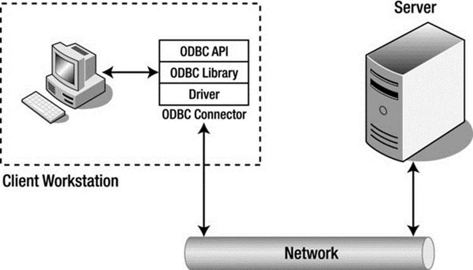
Figure 2-1. Client Application/database Server Communication
MYSQL CONNECTORS
Oracle provides several database connectors for developers to enable applications to interact with MySQL. These connectors can be used with applications and tools that are compatible with industry standards, including ODBC and JDBC. This means that any application that works with ODBC or JDBC can use the MySQL connector. The MySQL connectors available for Oracle are:
· Connector/ODBC – standard ODBC connector for Windows, Linux, Mac OS X, and Unix platforms.
· Connector/J[ava] – for Java platforms and development.
· Connector/Net – Windows .Net applications development.
· Connector/MXJ – MBean for embedding the MySQL server in Java applications.
· Connector/C++ – C++ development.
· Connector/C (libmysql) – C applications development.
· Connector/Python – Python applications development.
You can view and download the connectors from at http://www.mysql.com/downloads/connector/
Query Interface
A query language such as SQL is a language (it has a syntax and semantics) that can represent a question posed to a database system. In fact, the use of SQL in database systems is considered one of the major reasons for their success. SQL provides several language groups that form a comprehensive foundation for using database systems. The data definition language (DDL) is used by database professionals to create and manage databases. Tasks include creating and altering tables, defining indexes, and managing constraints. The data manipulation language (DML) is used by database professionals to query and update the data in databases. Tasks include adding and updating data as well as querying the data. These two language groups form the majority of commands that database systems support.
SQL commands are formed using a specialized syntax. The following presents the syntax of a SELECT command in SQL. The notation depicts user-defined variables in italics and optional parameters in square brackets ([]).
SELECT [DISTINCT] listofcolumns
FROM listoftables
[WHERE expression (predicates in CNF)]
[GROUP BY listofcolumns]
[HAVING expression]
[ORDER BY listof columns];
The semantics of this command are:7
1. Form the Cartesian product of the tables in the FROM clause, thus forming a projection of only those references that appear in other clauses.
2. If a WHERE clause exists, apply all expressions for the given tables referenced.
3. If a GROUP BY clause exists, form groups in the results on the attributes specified.
4. If a HAVING clause exists, apply a filter for the groups.
5. If an ORDER BY clause exists, sort the results in the manner specified.
6. If a DISTINCT keyword exists, remove the duplicate rows from the results.
The previous code example is representative of most SQL commands; all such commands have required portions, and most also have optional sections as well as keyword-based modifiers.
Once the query statements are transferred to the client via the network protocols (called shipping), the database server must then interpret and execute the command. A query statement from this point on is referred to simply as a query, because it represents the question for which the database system must provide an answer. Furthermore, in the sections that follow, I assume the query is of the SELECT variety, in which the user has issued a request for data. All queries, regardless whether they are data manipulation or data definition, follow the same path through the system, however. It is also at this point that we consider the actions being performed within the database server itself. The first step in that process is to decipher what the client is asking for—that is, the query must be parsed and broken down into elements that can be executed upon.
Query Processing
In the context of a database system operating in a client/server model, the database server is responsible for processing the queries presented by the client and returning the results accordingly. This has been termed query shipping, in which the query is shipped to the server and a payload (data) is returned. The benefits of query shipping are a reduction of communication time for queries and the ability to exploit server resources rather than using the more limited resources of the client to conduct the query. This model also permits a separation of how the data is stored and retrieved on the server from the way the data is used on the client. In other words, the client/server model supports data independence.
Data independence is one of the principal advantages of the relational model introduced by Codd in 1970: the separation of the physical implementation from the logical model. According to Codd,8
Users of large data banks must be protected from having to know how the data is organized in the machine . . . Activities of users at terminals and most application programs should remain unaffected when the internal representation of data is changed.
This separation allows a powerful set of logical semantics to be developed, independent of a particular physical implementation. The goal of data independence (called physical data independence by Elmasri and Navathe9) is that each of the logical elements is independent of all of the physical elements (see Table 2-1). For example, the logical layout of the data into relations (tables) with attributes (fields) arranged by tuples (rows) is completely independent of how the data is stored on the storage medium.
Table 2-1. The Logical and Physical Models of Database Design
|
Logical Model |
Physical Model |
|
Query language |
Sorting algorithms |
|
Relational Algebra |
Storage mechanisms |
|
Relational Calculus |
Indexing mechanisms |
|
Relvars |
Data representation |
One challenge of data independence is that database programming becomes a two-part process. First, there is the writing of the logical query—describing what the query is supposed to do. Second, there is the writing of the physical plan, which shows how to implement the logical query.
The logical query can be written, in general, in many different forms, such as a high-level language such as SQL or as an algebraic query tree.10 For example, in the traditional relational model, a logical query can be described in relational calculus or relational algebra. The relational calculus is better in terms of focusing on what needs to be computed. The relational algebra is closer to providing an algorithm that lets you find what you are querying for, but still leaves out many details involved in the evaluation of a query.
The physical plan is a query tree implemented in a way that it can be understood and processed by the database system’s query execution engine. A query tree is a tree structure in which each node contains a query operator and has a number of children that correspond to the number of tables involved in the operation. The query tree can be transformed via the optimizer into a plan for execution. This plan can be thought of as a program that the query execution engine can execute.
A query statement goes through several phases before it is executed; parsing, validation, optimization, plan generation/compilation, and execution. Figure 2-2 depicts the query processing steps that a typical database system would employ. Each query statement is parsed for validity and checked for correct syntax and for identification of the query operations. The parser then outputs the query in an intermediate form to allow the optimizer to form an efficient query execution plan. The execution engine then executes the query and the results are returned to the client. This progression is shown in Figure 2-2, where once parsing is completed the query is validated for errors, then optimized; a plan is chosen and compiled; and finally the query is executed.
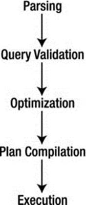
Figure 2-2. Query processing steps
The first step in this process is to translate the logical query from SQL into a query tree in relational algebra. This step, done by the parser, usually involves breaking the SQL statement into parts and then building the query tree from there. The next step is to translate the query tree in logical algebra into a physical plan. Generally, many plans could implement the query tree. The process of finding the best execution plan is called query optimization. That is, for some query-execution-performance measure (e.g., execution time), we want to find the plan with the best execution performance. The plan should be optimal or near optimal within the search space of the optimizer. The optimizer starts by copying the relational-algebra query tree into its search space. The optimizer then expands the search space by forming alternative execution plans (to a finite iteration) and then searching for the best plan (the one that executes fastest).
At this level of generality, the optimizer can be viewed as the code-generation part of a query compiler for the SQL language. In fact, in some database systems, the compilation step translates the query into an executable program. Most database systems, however, translate the query into a form that can be executed using the internal library of execution steps. The code compilation in this case produces code to be interpreted by the query-execution engine, except that the optimizer’s emphasis is on producing “very efficient” code. For example, the optimizer uses the database system’s catalog to get information (e.g., the number of tuples) about the stored relations referenced by the query, something traditional programming language compilers normally do not do. Finally, the optimizer copies the optimal physical plan out of its memory structure and sends it to the query-execution engine, which executes the plan using the relations in the stored database as input and produces the table of rows that match the query criteria.
All this activity requires additional processing time and places a greater burden on the process by forcing database implementers to consider the performance of the query optimizer and execution engine as a factor in their overall efficiency. This optimization is costly, because of the number of alternative execution plans that use different access methods (ways of reading the data) and different execution orders. Thus, it is possible to generate an infinite number of plans for a single query. Database systems typically bound the problem to a few known best practices, however.
A primary reason for the large number of query plans is that optimization will be required for many different values of important runtime parameters whose actual values are unknown at optimization time. Database systems make certain assumptions about the database contents (e.g., value distribution in relation attributes), the physical schema (e.g., index types), the values of the system parameters (e.g., the number of available buffers), and the values of the query constants.
Query Optimizer
Some mistakenly believe that the query optimizer performs all the steps outlined in the query-execution phases. As you will see, query optimization is just one step that the query takes on the way to be executed. The following paragraphs describe the query optimizer in detail and illustrate the role of the optimizer in the course of the query execution.
Query optimization is the part of the query-compilation process that translates a data-manipulation statement in a high-level, nonprocedural language, such as SQL, into a more detailed, procedural sequence of operators, called a query plan. Query optimizers usually select a plan by estimating the cost of many alternative plans and then choosing the least expensive among them (the one that executes fastest).
Database systems that use a plan-based approach to query optimization assume that many plans can be used to produce any given query. Although this is true, not all plans are equivalent in the number of resources (or cost) needed to execute the query, nor are all plans executed in the same amount of time. The goal, then, is to discover the plan that has the least cost and/or runs in the least amount of time. The distinction of either resource usage or cost usage is a trade-off often encountered when designing systems for embedded integration or running on a small platform (with low resource availability) versus the need for higher throughput (or time).
Figure 2-3 depicts a plan-based query-processing strategy in which the query follows the path of the arrows. The SQL command is passed to the query parser, where it is parsed and validated, and then translated into an internal representation, usually based on a relational-algebra expression or a query tree, as described earlier. The query is then passed to the query optimizer, which examines all of the algebraic expressions that are equivalent, generating a different plan for each combination. The optimizer then chooses the plan with the least cost and passes the query to the code generator, which translates the query into an executable form, either as directly executable or as interpretative code. The query processor then executes the query and returns a single row in the result set at a time.
This common implementation scheme is typical of most database systems. The machines that the database system runs on have improved over time, however. It is no longer the case that query plans have diverse execution costs. In fact, most query plans execute with approximately the same cost. This realization has led some database-system implementers to adopt a query optimizer that focuses on optimizing the query using some well-known best practices or rules (called heuristics), for query optimization. Some database systems use hybrids of optimization techniques that are based on one form while maintaining aspects of other techniques during execution.
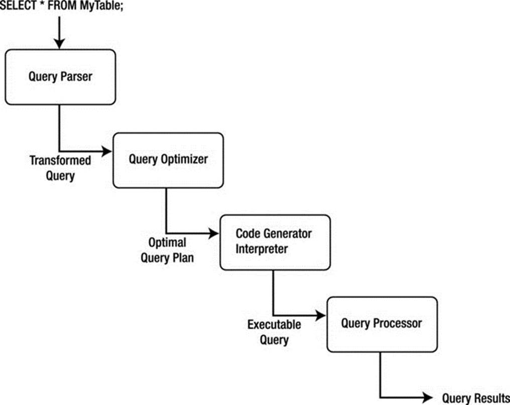
Figure 2-3. Plan-based query processing
The four primary means of performing query optimization are
· Cost-based optimization
· Heuristic optimization
· Semantic optimization
· Parametric optimization
Although no optimization technique can guarantee the best execution plan, the goal of all these methods is to generate an efficient execution for the query that guarantees correct results.
A cost-based optimizer generates a range of query-evaluation plans from the given query by using the equivalence rules, and it chooses the one with the least cost based on the metrics (or statistics) gathered about the relations and operations needed to execute the query. For a complex query, many equivalent plans are possible. The goal of cost-based optimization is to arrange the query execution and table access utilizing indexes and statistics gathered from past queries. Systems such as Microsoft SQL Server and Oracle use cost-based optimizers.
Heuristic optimizers use rules concerning how to shape the query into the most optimal form prior to choosing alternative implementations. The application of heuristics, or rules, can eliminate queries that are likely to be inefficient. Using heuristics to form the query plan ensures that the query plan is most likely (but not always) optimized prior to evaluation. The goal of heuristic optimization is to apply rules that ensure “good” practices for query execution. Systems that use heuristic optimizers include Ingres and various academic variants. These systems typically use heuristic optimization to avoid the really bad plans rather than as a primary means of optimization.
The goal of semantic optimization is to form query-execution plans that use the semantics, or topography, of the database and the relationships and indexes within to form queries that ensure the best practice available for executing a query in the given database. Though not yet implemented in commercial database systems as the primary optimization technique, semantic optimization is currently the focus of considerable research. Semantic optimization operates on the premise that the optimizer has a basic understanding of the actual database schema. When a query is submitted, the optimizer uses its knowledge of system constraints to simplify or to ignore a particular query if it is guaranteed to return an empty result set. This technique holds great promise for providing even more improvements to query processing efficiency in future RDBMSs.
Parametric query optimization combines the application of heuristic methods with cost-based optimization. The resulting query optimizer provides a means of producing a smaller set of effective query plans from which cost can be estimated, and thus, the lowest-cost plan of the set can be executed.
An example of a database system that uses a hybrid optimizer is MySQL. The query optimizer in MySQL is designed around a select-project-join strategy, which combines a cost-based and heuristic optimizer that uses known optimal mechanisms, thus resulting in fewer alternatives from which cost-based optimization can choose the minimal execution path. This strategy ensures an overall “good” execution plan, but it does not necessarily generate the best plan. This strategy has proven to work well for a vast variety of queries running in different environments. The internal representation of MySQL has been shown to perform well enough to rival the execution speeds of the largest of the production database systems.
An example of a database system that uses a cost-based optimizer is Microsoft’s SQL Server. The query optimizer in SQL Server is designed around a classic cost-based optimizer that translates the query statement into a procedure that can execute efficiently and return the desired results. The optimizer uses information, or statistics,11 collected from values recorded in past queries and the characteristics of the data in the database to create alternative procedures that represent the same query. The statistics are applied to each procedure to predict which one can be executed more efficiently. Once the most efficient procedure is identified, execution begins and results are returned to the client.
Optimization of queries can be complicated by using unbound parameters, such as a user predicate. For example, an unbound parameter is created when a query within a stored procedure accepts a parameter from the user when the stored procedure is executed. In this case, query optimization may not be possible, or it may not generate the lowest cost unless some knowledge of the predicate is obtained prior to execution. If very few records satisfy the predicate, even a basic index is far superior to the file scan. The opposite is true if many records qualify. If the selectivity is not known when optimization is performed because the predicate is unbound, the choice among these alternative plans should be delayed until execution.
The problem of selectivity can be overcome by building optimizers that can adopt the predicate as an open variable and perform query-plan planning by generating all possible query plans that are likely to occur based on historical query execution, and by utilizing the statistics from the cost-based optimizer, which include the frequency distribution for the predicate’s attribute.
Internal Representation of Queries
A query can be represented within a database system using several alternate forms of the original SQL command. These alternate forms exist due to redundancies in SQL, the equivalence of subqueries and joins under certain constraints, and logical inferences that can be drawn from predicates in the WHERE clause. Having alternate forms of a query poses a problem for database implementers, because the query optimizer must choose the optimal access plan for the query regardless of how it was originally formed by the user.
Once the query optimizer has either formed an efficient execution plan (heuristic and hybrid optimizers) or has chosen the most efficient plan (cost-based optimizers), the query is then passed to the next phase of the process: execution.
Query Execution
Database systems can use several methods to execute queries. Most use either an iterative or an interpretative execution strategy.
Iterative methods provide ways of producing a sequence of calls available for processing discrete operations (join, project, etc.), but they are not designed to incorporate the features of the internal representation. Translation of queries into iterative methods uses techniques of functional programming and program transformation. Several available algorithms generate iterative programs from algebra-based query specifications. For example, some algorithms translate query specifications into recursive programs, which are simplified by sets of transformation rules before the algorithm generates an execution plan. Another algorithm uses a two-level translation. The first level uses a smaller set of transformation rules to simplify the internal representation, and the second level applies functional transformations prior to generating the execution plan.
The implementation of this mechanism creates a set of defined compiled functional primitives, formed using a high-level language, that are then linked together via a call stack, or procedural call sequence. When a query-execution plan is created and selected for execution, a compiler (usually the same one used to create the database system) is used to compile the procedural calls into a binary executable. Due to the high cost of the iterative method, compiled execution plans are typically stored for reuse for similar or identical queries.
Interpretative methods, on the other hand, form query execution using existing compiled abstractions of basic operations. The query-execution plan chosen is reconstructed as a queue of method calls, which are each taken off the queue and processed. The results are then placed in memory for use with the next or subsequent calls. Implementation of this strategy is often called lazy evaluation because the set of available compiled methods is not optimized for best performance; rather, the methods are optimized for generality. Most database systems use the interpretative method of query execution.
One often-confusing area is the concept of compiled. Some database experts consider a compiled query to be an actual compilation of an iterative query-execution plan, but in Date’s work, a compiled query is simply one that has been optimized and stored for future execution. I won’t use the word compiled, because the MySQL query optimizer and execution engine do not store the query-execution plan for later reuse (an exception is the MySQL query cache). I don’t think we can compare or mention query cache here. The evaluation of the executed query is not even related to a plan, but instead is related to a literary comparison between SQL received and SQL stored directly related to a Set of already retrieved information, nor does the query execution require any compilation or assembly to work. Interestingly, the concept of a stored procedure fits this second category; it is compiled (or optimized) for execution at a later date and can be run many times on data that meet its input parameters.
Query execution evaluates each part of the query tree (or query as represented by the internal structures) and executes methods for each part. The methods supported mirror those operations defined in relational algebra, project, restrict, union, intersect, and so on. For each of these operations, the query-execution engine performs a method that evaluates the incoming data and passes the processed data along to the next step. For example, only some of the attributes (or columns) of data are returned in a project operation. In this case, the query-execution engine would strip the data for the attributes that do not meet the specification of the restriction and pass the remaining data to the next operation in the tree (or structure). Table 2-2 lists the most common operations supported and briefly describes each.
Table 2-2. Query Operations
|
Operation |
Description |
|
Restrict |
Returns tuples that match the conditions (predicate) of the WHERE clause (some systems treat the HAVING clause in the same or a similar manner). This operation is often defined as SELECT. |
|
Project |
Returns the attributes specified in the column list of the tuple evaluated. |
|
Join |
Returns tuples that match a special condition called the join condition (or join predicate). There are many forms of joins. See “Joins” for a description of each. |
JOINS
The join operation can take many forms. These are often confused by database professionals and in some cases avoided at all costs. The expressiveness of SQL permits many joins to be written as simple expressions in the WHERE clause. While most database systems correctly transform these queries into joins, it is considered a lazy form. The following lists the types of joins you are likely to encounter in an RDBMS and describes each. Join operations can have join conditions (theta joins), a matching of the attribute values being compared (equijoins), or no conditions (Cartesian products). The join operation is subdivided into:
· Inner: The join of two relations returning tuples where there is a match.
· Outer (left, right, full): Returns all rows from at least one of the tables or views mentioned in the FROM clause, as long as those rows meet any WHERE search conditions. All rows are retrieved from the left table referenced with a left outer join; all rows from the right table are referenced in a right outer join. All rows from both tables are returned in a full outer join. Values for attributes of nonmatching rows are returned as null values.
· Right outer: The join of two relations returning tuples where there is a match, plus all tuples from the relation specified to the right, leaving nonmatching attributes specified from the other relation empty (null).
· Full outer: The join of two relations returning all tuples from both relations, leaving nonmatching attributes specified from the other relation empty (null).
· Cross product: The join of two relations mapping each tuple from the first relation to all tuples from the other relation.
· Union: The set operation in which only matches from two relations with the same schema are returned.
· Intersect: The set operation in which only the nonmatches from two relations with the same schema are returned.
Deciding how to execute the query (or the chosen query plan) is only half of the story. The other thing to consider is how to access the data. There are many ways to read and write data to and from disk (files), but choosing the optimal one depends on what the query is trying to do. File-access mechanisms are created to minimize the cost of accessing the data from disk and maximize the performance of query execution.
File Access
The file-access mechanism, also called the physical database design, has been important since the early days of database-system development. The significance of file access has lessened due to the effectiveness and simplicity of common file systems supported by operating systems, however. Today, file access is merely the application of file storage and indexing best practices, such as separating the index file from the data file and placing each on a separate disk input/output (I/O) system to increase performance. Some database systems use different file-organization techniques to enable the database to be tailored to specific application needs. MySQL is perhaps the most unique in this regard due to the numerous file-access mechanisms (called storage engines) it supports.
Clear goals must be satisfied to minimize the I/O costs in a database system. These include utilizing disk data structures that permit efficient retrieval of only the relevant data through effective access paths, and organizing data on disk so that the I/O cost for retrieving relevant data is minimized. The overriding performance objective is thus to minimize the number of disk accesses (or disk I/Os).
Many techniques for approaching database design are available. Fewer are available for file-access mechanisms (the actual physical implementation of the data files). Furthermore, many researchers agree that the optimal database design (from the physical point of view) is not achievable in general and, furthermore, should not be pursued. Optimization is not achievable, mainly because of the much-improved efficiency of modern disk subsystems. Rather, it is the knowledge of these techniques and research that permits the database implementer to implement the database system in the best manner possible to satisfy the needs of those who will use the system.
To create a structure that performs well, you must consider many factors. Early researchers considered segmenting the data into subsets based on the content or the context of the data. For example, all data containing the same department number would be grouped together and stored with references to the related data. This process can be perpetuated in that sets can be grouped together to form supersets, thus forming a hierarchical file organization.
Accessing data in this configuration involves scanning the sets at the highest level to access and scan only those sets that are necessary to obtain the desired information. This process significantly reduces the number of elements to be scanned. Keeping the data items to be scanned close together minimizes search time. The arrangement of data on disk into structured files is called file organization. The goal is to design an access method that provides a way of immediately processing transactions one by one, thereby allowing us to keep an up-to-the-second stored picture of the real-world situation.
File-organization techniques were revised as operating systems evolved in order to ensure greater efficiency of storage and retrieval. Modern database systems create new challenges for which currently accepted methods may be inadequate. This is especially true for systems that execute on hardware with increased disk speeds with high data throughput. Additionally, understanding database design approaches, not only as they are described in textbooks but also in practice, will increase the requirements levied against database systems and thus increase the drive for further research. For example, the recent adoption of redundant and distributed systems by industry has given rise to additional research in these areas to make use of new hardware and/or the need to increase data availability, security, and recovery.
Since accessing data from disk is expensive, the use of a cache mechanism, sometimes called a buffer, can significantly improve read performance from disk, thus reducing the cost of storage and retrieval of data. The concept involves copying parts of the data either in anticipation of the next disk read or based on an algorithm designed to keep the most frequently used data in memory. The handling of the differences between disk and main memory effectively is at the heart of a good-quality database system. The trade-off between the database system using disk or using main memory should be understood. See Table 2-3 for a summary of the performance trade-offs between physical storage (disk) and secondary storage (memory).
Table 2-3. Performance Trade-offs
|
Issue |
Main Memory vs. Disk |
|
Speed |
Main memory is at least 1,000 times faster than disk. |
|
Storage space |
Disk can hold hundreds of times more information than memory for the same cost. |
|
Persistence |
When the power is switched off, disk keeps the data, and main memory forgets everything. |
|
Access time |
Main memory starts sending data in nanoseconds, while disk takes milliseconds. |
|
Block size |
Main memory can be accessed one word at a time, and disk one block at a time. |
Advances in database physical storage have seen many of the same improvements with regard to storage strategies and buffering mechanisms, but little in the way of exploratory examination of the fundamental elements of physical storage has occurred. Some have explored the topic from a hardware level and others from a more pragmatic level of what exactly it is we need to store. The subject of persistent storage is largely forgotten, because of the capable and efficient mechanisms available in the host operating system.
File-access mechanisms are used to store and retrieve the data that are encompassed by the database system. Most file-access mechanisms have additional layers of functionality that permit locating data within the file more quickly. These layers are called index mechanisms. Index mechanisms provide access paths (the way data will be searched for and retrieved) designed to locate specific data based on a subpart of the data called a key. Index mechanisms range in complexity from simple lists of keys to complex data structures designed to maximize key searches.
The goal is to find the data we want quickly and efficiently, without having to request and read more disk blocks than absolutely necessary. This can be accomplished by saving values that identify the data (or keys) and the location on disk of the record to form an index of the data. Furthermore, reading the index data is faster than reading all of the data. The primary benefit of using an index is that it allows us to search through large amounts of data efficiently without having to examine, or in many cases read, every item until we find the one we are searching for. Indexing, therefore, is concerned with methods of searching large files containing data that is stored on disk. These methods are designed for fast random access of data as well as sequential access of the data.
Most, but not all, index mechanisms involve a tree structure that stores the keys and the disk block addresses. Examples include B-trees, B + trees, and hash trees. The structures are normally traversed by one or more algorithms designed to minimize the time spent searching the structure for a key. Most database systems use one form or another of the B-tree in their indexing mechanisms. These tree algorithms provide very fast search speeds without requiring a large memory space.
During the execution of the query, interpretative query execution methods access the assigned index mechanism and request the data via the access method specified. The execution methods then read the data, typically a record at a time; analyze the query for a match to the predicate by evaluating the expressions; and then pass the data through any transformations and finally on to the transmission portion of the server to send the data back to the client.
Query Results
Once all the tuples in the tables referenced in the query have been processed, the tuples are returned to the client, following the same, or sometimes alternative, communication pathways. The tuples are then passed on to the ODBC connector for encapsulation and presentation to the client application.
Relational Database Architecture Summary
In this section, I’ve detailed the steps taken by a query for data through a typical relational-database system architecture. As you’ll see, the query begins with an SQL command issued by the client; then it is passed via the ODBC connector to the database system using a communications pathway (network). The query is parsed, transformed into an internal structure, optimized, and executed, and the results are returned to the client.
Now that I’ve given you a glimpse of all the steps involved in processing a query, and you’ve seen the complexity of the database system subcomponents, it is time to take a look at a real-world example. In the following section, I present an in-depth look at the MySQL database-system architecture.
The MySQL Database System
The MySQL source code is a highly organized and built using many structured classes (some are complex data structures and some are objects, but most are structures). While efforts toward making the system more modular through the addition of plugins are underway, the source code is not yet a truly modular architecture but is much closer now with the new plugin mechanism. It is important to understand this as you explore the architecture and more important later, when you explore the source code. This means that you will sometimes find instances in which no clear division of architecture elements exists in the source code. For more information about the MySQL source code, including how to obtain it, see Chapter 3.
Although some may present the MySQL architecture as a component-based system built from a set of modular subcomponents, the reality is that, while highly organized, it is neither component based nor modular. The source code is built using a mixture of C and C++, and a number of objects are utilized in many of the functions of the system. The system is not object oriented in the true sense of object-oriented programming. Rather, the system is built on the basis of function libraries and data structures designed to optimize the organization of the source code around that of the architecture, with some portions written using objects.
MySQL architecture is, however, an intelligent design of highly organized subsystems working in harmony to form an effective and highly reliable database system. All of the technologies I described previously in this chapter are present in the system. The subsystems that implement these technologies are well designed and implemented with the same precision source code found throughout the system. It is interesting to note that many accomplished C and C++ programmers remark upon the elegance and leanness of the source code. I’ve often found myself marveling at the serene complexity and yet elegance of the code. Indeed, even the code authors themselves admit that their code has a sort of genius intuition that is often not fully understood or appreciated until it is thoroughly analyzed. You, too, will find yourself amazed at how well some of the source code works and how simple it is once you figure it out.
![]() Note The MySQL system has proved to be difficult for some to learn and troublesome to diagnose when things go awry. It is clear, however, that once one has mastered the intricacies of the MySQL architecture and source code, the system is very accommodating and has the promise of being perhaps the first and best platform for experimental database work.
Note The MySQL system has proved to be difficult for some to learn and troublesome to diagnose when things go awry. It is clear, however, that once one has mastered the intricacies of the MySQL architecture and source code, the system is very accommodating and has the promise of being perhaps the first and best platform for experimental database work.
What this means is that the MySQL architecture and source code is often challenging for novice C++ programmers. If you find yourself starting to reconsider taking on the source code, please keep reading; I will be your guide in navigating the source code. But let’s first begin with a look at how the system is structured.
MySQL System Architecture
The MySQL architecture is best described as a layered system of subsystems. While the source code isn’t compiled as individual components or modules, the source code for the subsystems is organized in a hierarchical manner that allows subsystems to be segregated (encapsulated) in the source code. Most subsystems rely on base libraries for lower-level functions (e.g., thread control, memory allocation, networking, logging and event handling, and access control). Together, the base libraries, subsystems built on those libraries, and even subsystems built from other subsystems form the abstracted API that is known as the C client API. This powerful API permits the MySQL system to be used as either a stand-alone server or an embedded database system in a larger application.
The architecture provides encapsulation for a SQL interface, query parsing, query optimization and execution, caching and buffering, and a pluggable storage engine. Figure 2-4 depicts the MySQL architecture and its subsystems. At the top of the drawing are the database connectors that provide access to client applications. As you can see, a connector for just about any programming environment you could want exists. To the left of the drawing, the ancillary tools are listed grouped by administration and enterprise services. For a complete discussion of the administration and enterprise service tools, see Michael Kruckenberg and Jay Pipes’s Pro MySQL12 an excellent reference for all things administrative for MySQL.
The next layer down in the architecture from the connectors is the connection pool layer. This layer handles all of the user-access, thread processing, memory, and process cache needs of the client connection. Below that layer is the heart of the database system. Here is where the query is parsed and optimized, and file access is managed. The next layer down from there is the pluggable storage-engine layer. At this layer, part of the brilliance of the MySQL architecture shines. The pluggable storage-engine layer permits the system to be built to handle a wide range of diverse data or file storage and retrieval mechanisms. This flexibility is unique to MySQL. No other database system available today provides the ability to tune databases by providing several data storage mechanisms.
![]() Note The pluggable storage-engine feature is available beginning in version 5.1.
Note The pluggable storage-engine feature is available beginning in version 5.1.
Below the pluggable storage engine is the lowest layer of the system, the file-access layer. At this layer, the storage mechanisms read and write data, and the system reads and writes log and event information. This layer is the closest to the operating system, along with thread, process, and memory control.
Let’s begin our discussion of the MySQL architecture with the flow through the system from the client application to the data and back. The first layer encountered once the client connector (ODBC, .NET, JDBC, C API, etc.) has transmitted the SQL statements to the server is the SQL interface.
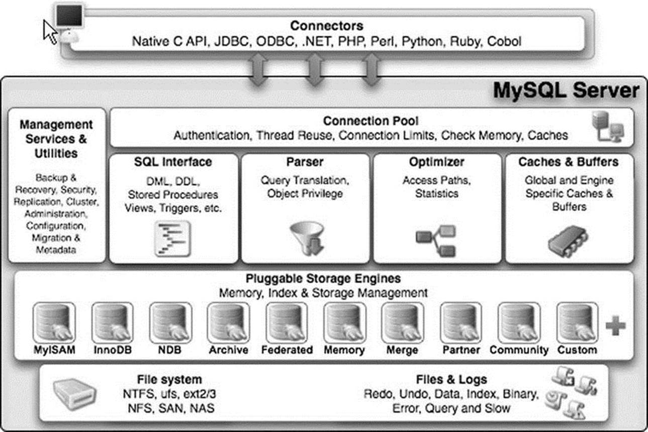
Figure 2-4. MySQL server architecture (Copyright Oracle. Reprinted with kind permission.)
SQL Interface
The SQL interface provides the mechanisms to receive commands and transmit results to the user. The MySQL SQL interface was built to the ANSI SQL standard and accepts the same basic SQL statements as most ANSI-compliant database servers. Although many of the SQL commands supported in MySQL have options that are not ANSI standard, the MySQL developers have stayed very close to the ANSI SQL standard.
Connections to the database server are received from the network communication pathways, and a thread is created for each. The threaded process is the heart of the executable pathway in the MySQL server. MySQL is built as a true multithreaded application whereby each thread executes independently of the other threads (except for certain helper threads). The incoming SQL command is stored in a class structure and the results are transmitted to the client by writing the results out to the network communication protocols. Once a thread has been created, the MySQL server attempts to parse the SQL command and store the parts in the internal data structure.
Parser
When a client issues a query, a new thread is created and the SQL statement is forwarded to the parser for syntactic validation (or rejection due to errors). The MySQL parser is implemented using a large Lex-YACC script that is compiled with Bison. The parser constructs a query structure used to represent the query statement (SQL) in memory as a tree structure (also called an abstract syntax tree) that can be used to execute the query.
![]() Tip The sql_yacc.yy, sql_lex.h, and lex.h files are where you would begin to construct your own SQL commands or data types in MySQL. These files will be discussed in more detail in Chapter 7.
Tip The sql_yacc.yy, sql_lex.h, and lex.h files are where you would begin to construct your own SQL commands or data types in MySQL. These files will be discussed in more detail in Chapter 7.
Considered by many to be the most complex part of the MySQL source code and the most elegant, the parser is implemented using Lex and YACC, which were originally built for compiler construction. These tools are used to build a lexical analyzer that reads a SQL statement and breaks the statement into parts, assigning the command portions, options, and parameters to a structure of variables and lists. This structure (named imaginatively Lex) is the internal representation of the SQL query. As a result, this structure is used by every other step in the query process. The Lex structure contains lists of tables being used, field names referenced, join conditions, expressions, and all the parts of the query stored in a separate space.
The parser works by reading the SQL statement and comparing the expressions (consisting of tokens and symbols) with rules defined in the source code. These rules are built into the code using Lex and YACC and later compiled with Bison to form the lexical analyzer. If you examine the parser in its C form (a file named /sql/sql_yacc.cc), you may become overwhelmed with the terseness and sheer enormity of the switch statement.13 A better way to examine the parser is to look at the Lex and YACC form prior to compilation (a file named /sql/sql_yacc.yy). This file contains the rules as written for YACC and is much easier to decipher. The construction of the parser illustrates Oracle’s open source philosophy at work: why create your own language handler when special compiler construction tools such as Lex, YACC, and Bison are designed to do just that?
Once the parser identifies a regular expression and breaks the query statement into parts, it assigns the appropriate command type to the thread structure and returns control to the command processor (which is sometimes considered part of the parser, but more correctly is part of the main code). The command processor is implemented as a large switch statement with cases for every command supported. The query parser checks only the correctness of the SQL statement. It does not verify the existence of tables or attributes (fields) referenced, nor does it check for semantic errors, such as an aggregate function used without a GROUP BY clause. Instead, the verification is left to the optimizer. Thus, the query structure from the parser is passed to the query processor. From there, control switches to the query optimizer.
LEX AND YACC
Lex stands for “lexical analyzer generator” and is used as a parser to identify tokens and literals as well as the syntax of a language. YACC stands for “yet another compiler compiler” and is used to identify and act on the semantic definitions of the language. The use of these tools together with Bison (a YACC compiler) provides a rich mechanism for creating subsystems that can parse and process language commands. Indeed, that is exactly how MySQL uses these technologies.
Query Optimizer
The MySQL query-optimizer subsystem is considered by some to be misnamed. The optimizer used is a SELECT-PROJECT-JOIN strategy that attempts to restructure the query by first doing any restrictions (SELECT) to narrow the number of tuples to work with, then performs the projections to reduce the number of attributes (fields) in the resulting tuples, and finally evaluates any join conditions. While not considered a member of the extremely complicated query-optimizer category, the SELECT-PROJECT-JOIN strategy falls into the category of heuristic optimizers. In this case, the heuristics (rules) are simply:
· Eliminate extra data by evaluating the expressions in the WHERE (HAVING) clause.
· Eliminate extra data by limiting the data to the attributes specified in the attribute list. The exception is the storage of the attributes used in the join clause that may not be kept in the final query.
· Evaluate join expressions.
This results in a strategy that ensures a known-good access method to retrieve data in an efficient manner. Despite critical reviews, the SELECT-PROJECT-JOIN strategy has proven effective at executing the typical queries found in transaction processing. Figure 2-5 depicts a block diagram that describes the MySQL query processing methodology.
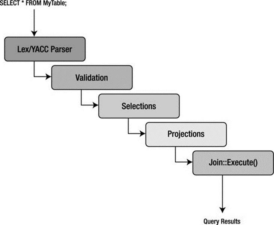
Figure 2-5. MySQL query processing methodology
The first step in the optimizer is to check for the existence of tables and access control by the user. If there are errors, the appropriate error message is returned and control returns to the thread manager, or listener. Once the correct tables have been identified, they are opened, and the appropriate locks are applied for concurrency control.
Once all the maintenance and setup tasks are complete, the optimizer uses the internal-query structure (Lex) and evaluates the WHERE conditions (a restrict operation) of the query. Results are returned as temporary tables to prepare for the next step. If UNION operators are present, the optimizer executes the SELECT portions of all statements in a loop before continuing.
The next step in the optimizer is to execute the projections. These are executed in a similar manner as the restrict portions, again storing the intermediate results as temporary tables and saving only those attributes specified in the column specification in the SELECT statement. Last, the structure is analyzed for any JOIN conditions that are built using the join class, and then the join::optimize() method is called. At this stage, the query is optimized by evaluating the expressions and eliminating any conditions that result in dead branches or always-true or always-false conditions (as well as many other similar optimizations). The optimizer is attempting to eliminate any known-bad conditions in the query before executing the join. This is done because joins are the most expensive and time consuming of all relational operators. Note that the join-optimization step is performed for all queries that have a WHERE or HAVING clause regardless of whether there are any join conditions. This enables developers to concentrate all of the expression-evaluation code in one place. Once the join optimization is complete, the optimizer uses a series of conditional statements to route the query to the appropriate library method for execution.
The query optimizer and execution engine is perhaps the second most difficult area to understand, because of its SELECT-PROJECT-JOIN optimizer approach. Complicating matters is that this portion of the server is a mixture of C and C++ code, where the typical select execution is written as C methods while the join operation is written as a C++ object. In Chapter 13, I show you how to write your own query optimizer and use it instead of the MySQL optimizer.
Query Execution
Execution of the query is handled by a set of library methods designed to implement a particular query. For example, the mysql_insert() method is designed to insert data. Likewise, there is a mysql_select() method designed to find and return data matching the WHERE clause. This library of execution methods is located in a variety of source-code files under a file of a similar name (e.g., sql_insert.cc or sql_select.cc). All these methods have as a parameter a thread object that permits the method to access the internal query structure and eases execution. Results from each of the execution methods are returned using the network-communication-pathways library. The query-execution library methods are clearly implemented using the interpretative model of query execution.
Query Cache
While not its own subsystem, the query cache should be considered a vital part of the query optimization and execution subsystem. The query cache is a marvelous invention that caches not only the query structure but also the query results themselves. This enables the system to check for frequently used queries and shortcut the entire query-optimization and -execution stages altogether. This is another technology unique to MySQL. Other database-systems cache queries, but no others cache the actual results. As you can appreciate, the query cache must also allow for situations in which the results are “dirty” in the sense that something has changed since the last time the query was run (e.g., an INSERT, UPDATE, or DELETE was run against the base table) and that the cached queries may need to be occasionally purged.
![]() Tip The query cache is turned on by default. If you want to turn off the query cache for the specific SQL statment, use the SQL_NO_CACHE SELECT option: SELECT SQL_NO_CACHE id, lname FROM myCustomer;. Otherwise, it can be GLOBALY disable using the server variables (query_cache_type, query_cache_size to also deallocate the buffer).
Tip The query cache is turned on by default. If you want to turn off the query cache for the specific SQL statment, use the SQL_NO_CACHE SELECT option: SELECT SQL_NO_CACHE id, lname FROM myCustomer;. Otherwise, it can be GLOBALY disable using the server variables (query_cache_type, query_cache_size to also deallocate the buffer).
If you are not familiar with this technology, try it out. Find a table that has a sufficient number of tuples and execute a query that has some complexity, such as a JOIN or complex WHERE clause. Record the time it took to execute, then execute the same query again. Note the time difference. This is the query cache in action.
Listing 2-1 illustrates this exercise using the SHOW command to display the system variables associated with the query cache. Notice how running the query multiple times adds it to the cache, and subsequent calls read it from the cache. Notice also that the SQL_NO_CACHE option does not affect the query cache variables (because it doesn’t use the query cache).
Listing 2-1. The MySQL Query Cache in Action
mysql> CREATE DATABASE test_cache;
Query OK, 1 row affected (0.00 sec)
mysql> CREATE TABLE test_cache.tbl1 (a int);
Query OK, 0 rows affected (0.01 sec)
mysql> INSERT INTO test_cache.tbl1 VALUES (100), (200), (300);
Query OK, 3 rows affected (0.00 sec)
Records: 3 Duplicates: 0 Warnings: 0
mysql> USE test_cache;
Database changed
mysql> SELECT * FROM tbl1;
+------+
| a |
+------+
| 100 |
| 200 |
| 300 |
+------+
3 rows in set (0.00 sec)
mysql> show status like "Qcache_hits";
+---------------+-------+
| Variable_name | Value |
+---------------+-------+
| Qcache_hits | 0 |
+---------------+-------+
1 row in set (0.00 sec)
mysql> select length(now()) from tbl1;
+---------------+
| length(now()) |
+---------------+
| 19 |
| 19 |
| 19 |
+---------------+
3 rows in set (0.00 sec)
mysql> show status like "Qcache_hits";
+---------------+-------+
| Variable_name | Value |
+---------------+-------+
| Qcache_hits | 0 |
+---------------+-------+
1 row in set (0.01 sec)
mysql> show status like "Qcache_inserts";
+----------------+-------+
| Variable_name | Value |
+----------------+-------+
| Qcache_inserts | 1 |
+----------------+-------+
1 row in set (0.00 sec)
mysql> show status like "Qcache_queries_in_cache";
+-------------------------+-------+
| Variable_name | Value |
+-------------------------+-------+
| Qcache_queries_in_cache | 1 |
+-------------------------+-------+
1 row in set (0.00 sec)
mysql> SELECT * FROM tbl1;
+------+
| a |
+------+
| 100 |
| 200 |
| 300 |
+------+
3 rows in set (0.00 sec)
mysql> show status like "Qcache_hits";
+---------------+-------+
| Variable_name | Value |
+---------------+-------+
| Qcache_hits | 1 |
+---------------+-------+
1 row in set (0.00 sec)
mysql> SELECT SQL_NO_CACHE * FROM tbl1;
+------+
| a |
+------+
| 100 |
| 200 |
| 300 |
+------+
3 rows in set (0.00 sec)
mysql> show status like "Qcache_hits";
+---------------+-------+
| Variable_name | Value |
+---------------+-------+
| Qcache_hits | 1 |
+---------------+-------+
1 row in set (0.00 sec)
mysql> SELECT * FROM tbl1;
+------+
| a |
+------+
| 100 |
| 200 |
| 300 |
+------+
3 rows in set (0.00 sec)
mysql> show status like "Qcache_hits";
+---------------+-------+
| Variable_name | Value |
+---------------+-------+
| Qcache_hits | 2 |
+---------------+-------+
1 r
mysql>
Cache and Buffers
The caching and buffers subsystem is responsible for ensuring that the most frequently used data (or structures, as you will see) are available in the most efficient manner possible. In other words, the data must be resident, or ready to read, at all times. The caches dramatically increase the response time for requests for that data, because the data are in memory, and thus no additional disk access is necessary to retrieve it. The cache subsystem was created to encapsulate all of the caching and buffering into a loosely coupled set of library functions. Although you will find the caches implemented in several different source-code files, they are considered part of the same subsystem.
A number of caches are implemented in this subsystem. Most cache mechanisms use the same or similar concept of storing data as structures in a linked list. The caches are implemented in different portions of the code to tailor the implementation to the type of data that is being cached. Let’s look at each of the caches.
Table Cache
The table cache was created to minimize the overhead in opening, reading, and closing tables (the .FRM files on disk). For this reason, it is designed to store metadata about the tables in memory. It does so by utilizing a data-chunking mechanism called Unireg. Unireg, a format created by a founder of MySQL, was once used for writing TTY applications. It stores data in segments called screens that originally were designed to be used to display data on a monitor. Unireq made it easier to store data and formulate displays (screens) for faster data refresh. As you may have surmised, this is an antiquated technology, and it shows the age of the MySQL source code. The good news is there are plans under way to redesign the table cache and eventually replace or remove the Unireg mechanism.
A WORD ABOUT FRM FILES
If you examine the data directory of a MySQL installation, you will see a folder named data that contains subfolders named for each database created. In these folders, you will see files named with the table names and a file extension of .frm. Many MySQL developers call these files “FRM files”. Thus, a table named table1 in database1 has an FRM file named /data/database1/table1.frm.
When you attempt to open these files, you will see that they are binary files, not readable by normal means. Indeed, the format of the files have been a mystery for many years. Since the FRM files contain the metadata for the table, all of the column definitions and table options, including index definitions, are stored in the file. This means it should be possible to extract the data needed to reconstruct the CREATE TABLE statement from a FRM file. Unfortunately, given the interface and uniqueness of Unireg, it is not easy to parse these files for the information. Fortunately, there are efforts under way to decipher the FRM files via a Python utility that is part of the MySQL Utilities plugin for MySQL Workbench. If you need to read an FRM file to recover a table, see the online MySQL Utilities documentation for more details:http://dev.mysql.com/doc/workbench/en/mysql-utilities.html
This makes it much faster for a thread to read the schema of the table without having to reopen the file every time. Each thread has its own list of table cache structures. This permits the threads to maintain their own views of the tables so that if one thread is altering the schema of a table (but has not committed the changes) another thread may use that table with the original schema. The structure used is a simple one that includes all of the metadata information for a table. The structures are stored in a linked list in memory and associated with each thread.
Buffer Pool
The buffer pool is a special cache used by the InnoDB storage engine. It caches table and index data, allowing data and indexes that are used most often to be read from memory instead of rereading from disk. The buffer pool improves performance significantly. Depending on your access patterns, you can tune the buffer pool to allocate more physical memory. It is one of the key parameters used to tune InnoDB storage-engine performance.
InnoDB uses several other caches. If you require additional performance from your InnoDB installation, consult the “InnoDB Performance Tuning and Troubleshooting” section in the online reference manual for InnoDB tuning best practices.
Record Cache
The record cache was created to enhance sequential reads from the storage engines. Thus, the record cache usually is used only during table scans. It works like a read-ahead buffer by retrieving one block of data at a time, thus resulting in fewer disk accesses during the scan. Fewer disk accesses generally equate to improved performance. Interestingly, the record cache is also used in writing data sequentially by writing the new (or altered) data to the cache first and then writing the cache to disk when full. In this way, write performance is improved as well. This sequential behavior (called locality of reference) is the main reason the record cache is most often used with the MyISAM storage engine, although it is not limited to MyISAM. The record cache is implemented in an agnostic manner that doesn’t interfere with the code used to access the storage engine API. Developers don’t have to do anything to take advantage of the record cache, as it is implemented within the layers of the API.
Key Cache
The key cache is a buffer for frequently used index data. In this case, it is a block of data for the index file (B-tree) and is used exclusively for MyISAM tables (the .MYI files on disk). The indexes themselves are stored as linked lists within the key cache structure. A key cache is created when a MyISAM table is opened for the first time. The key cache is accessed on every index read. If an index is found in the cache, it is read from there; otherwise, a new index block must be read from disk and placed into the cache. The cache has a limited size and is tunable by changing thekey_cache_block_size configuration variable. Thus, not all blocks of the index file will fit into memory. So how does the system keep track of which blocks have been used?
The cache implements a monitoring system to keep track of how frequently the index blocks are used. The key cache has been implemented to keep track of how “warm” the index blocks are. Warm, in this case, refers to how many times the index block has been accessed over time. Values for warm include BLOCK_COLD, BLOCK_WARM, and BLOCK_HOT. As the blocks cool off and new blocks become warm, the cold blocks are purged and the warm blocks added. This strategy is a least recently used (LRU) page-replacement strategy—the same algorithm used for virtual memory management and disk buffering in operating systems—that has been proven to be remarkably efficient even in the face of much more sophisticated page-replacement algorithms. In a similar way, the key cache keeps track of the index blocks that have changed (called getting “dirty”). When a dirty block is purged, its data are written back to the index file on disk before being replaced. Conversely, when a clean block is purged, data are simply removed from memory.
![]() Note Practice has shown that the LRU algorithm performs within 80 percent of the best algorithms. In a world in which time is precious and simplicity ensures reliability, the 80 percent solution is a win-win.
Note Practice has shown that the LRU algorithm performs within 80 percent of the best algorithms. In a world in which time is precious and simplicity ensures reliability, the 80 percent solution is a win-win.
Privilege Cache
The privilege cache is used to store grant data on a user account. This data are stored in the same manner as an access control list (ACL), which lists all of the privileges a user has for an object in the system. The privilege cache is implemented as a structure stored in a first-in, last-out (FILO) hash table. Data for the cache are gathered when the grant tables are read during user authentication and initialization. It is important to store this data in memory, because that saves a lot of time reading the grant tables.
Hostname Cache
The hostname cache is another helper cache, like the privilege cache. It, too, is implemented as a stack of a structure. It contains the hostnames of all the connections to the server. It may seem surprising, but this data are frequently requested and therefore in high demand and candidates for a dedicated cache.
Miscellaneous
A number of other small cache mechanisms are implemented throughout the MySQL source code. One is the join buffer cache, which is used during complex join operations. For example, some join operations require comparing one tuple to all the tuples in the second table. A cache in this case can store the tuples read so that the join can be implemented without having to reread the second table into memory multiple times.
File Access via Pluggable Storage Engines
One of the best features of MySQL is the ability to support different storage engines, or file types. This allows database professionals to tune their database performance by selecting the storage engine that best meets their application needs. Examples include using storage engines that provide transaction control for highly active databases for which transaction processing is required or using the memory storage engine whenever a table is read many times but seldom updated (e.g., a lookup table).
Oracle added a new architectural design in version 5.1 that makes it easier to add new storage types. The new mechanism is called the MySQL pluggable storage engine. Oracle has worked hard to make the server extensible via the pluggable storage engine. The pluggable storage engine was created as an abstraction of the file-access layer and built as an API that Oracle (or anyone) can use to build specialized file-access mechanisms called storage engines. The API provides a set of methods and access utilities for reading and writing data. These methods combine to form a standardized modular architecture that permits storage engines to use the same methods for every storage engine (this is the essence of why it is called pluggable—the storage engines all plug into the server using the same API). It also enables the use of storage-engine plugins.
PLUGGABLE VS PLUGIN
Pluggable is the concept that there may be several different implementations of a common interface allowing the exchange of the implementations while other portions of the system to remain unchanged. A plugin is a binary form of a module (a compiled module) that implements a pluggable interface. A plugin is therefore something that can be changed at runtime. The InnoDB storage engine is also a plugin, as are several of the modules in MySQL with plans to make other portions of the server into plugins.
To enable a plugin storage engine, use the INSTALL PLUGIN command. For example, to load the example plugin storage engine, issue the following command (example is for Linux OS):
mysql > INSTALL PLUGIN example SONAME 'ha_example.so';
Similarly, to unplug a storage engine, use the UNINSTALL PLUGIN command:
mysql > UNINSTALL PLUGIN example;
Alternatively, you can use the mysql_plugin client tool to enable and disable a storage engine plugin.
Perhaps most interesting of all is the fact that database implementers (you!) can assign a different storage engine to each table in a given database and even change storage engines after a table is created. This flexibility and modularity permits you to create new storage engines as the need arises. To change storage engines for a table, issue a command such as the following:
ALTER TABLE MyTable
ENGINE = InnoDB;
The pluggable storage engine is perhaps the most unusual feature of MySQL. No other database system comes close to having this level of flexibility and extensibility for the file-access layer of the architecture. The following sections describe all of the storage engines available in the server and present a brief overview of how you can create your own storage engine. I show you how to create your own storage engine in Chapter 10.
The strengths and weaknesses of the storage engines are many and varied. For example, some storage engines offered in MySQL support concurrency. As of version 5.6, the default storage engine for MySQL is InnoDB. The InnoDB tables support record locking (sometimes called row-level locking) for concurrency control; when an update is in progress, no other processes can access that row in the table until the operation is complete. Thus, the InnoDB table type provides an advantage for use in situations in which many concurrent updates are expected. Any of these storage engines, however, will perform well in read-only environments. such as web servers or kiosk applications.
![]() Tip You can change the default storage engine by setting the STORAGE_ENGINE configuration server variable.
Tip You can change the default storage engine by setting the STORAGE_ENGINE configuration server variable.
Previous versions of MySQL had the MyISAM storage engine as the default. MyISAM supports table-level locking for concurrency control. That is, when an update is in progress, no other processes can access any data from the same table until the operation is completed. The MyISAM storage engine is also the fastest of the available types due to optimizations made using indexed sequential access method (ISAM) principles. The Berkeley Database (BDB) tables support page-level locking for concurrency control; when an update is in progress, no other processes can access any data from the same page as that of the data being modified until the operation is complete.
Concurrency operations such as those we’ve discussed are implemented in database systems using specialized commands that form a transaction subsystem. Currently, only three of the storage engines listed support transactions: InnoDB and NDB. Transactions provide a mechanism that permits a set of operations to execute as a single atomic operation. For example, if a database were built for a banking institution, the macro operations of transferring money from one account to another would preferably be executed completely (money removed from one account and placed in another) without interruption. Transactions permit these operations to be encased in an atomic operation that will back out any changes should an error occur before all operations are complete, thus avoiding data being removed from one table and never making it to the next table. A sample set of operations in the form of SQL statements encased in transactional commands is:
START TRANSACTION;
UPDATE SavingsAccount SET Balance = Balance – 100
WHERE AccountNum = 123;
UPDATE CheckingAccount SET Balance = Balance + 100
WHERE AccountNum = 345;
COMMIT;
In practice, most database professionals specify the MyISAM table type if they require faster access and InnoDB if they need transaction support. Fortunately, MySQL provides facilities to specify a table type for each table in a database. In fact, tables within a database do not have to be the same type. This variety of storage engines permits the tuning of databases for a wide range of applications.
Interestingly, you can extend this list of storage engines by writing your own table handler. MySQL provides examples and code stubs to make this feature accessible to the system developer. The ability to extend this list of storage engines makes it possible to add support to MySQL for complex, proprietary data formats and access layers.
InnoDB
InnoDB is an Oracle storage engine that predates Oracles’ acquisition of MySQL via the purchase of Sun MicroSystems. InnoDB was originally a third-party storage engine licensed from Innobase (www.innodb.com) and distributed under the GNU Public License (GPL) agreement. Innobase was acquired by Oracle, and until the acquisition of MySQL it was licensed for use by MySQL. Hence, now that Oracle owns both MySQL and InnoDB, it removes any licensing limitations and enables the two product-development teams to coordinate development. Gains from this relationship have been seen most recently in the significant performance improvements in the latest releases of MySQL.
InnoDB is most often used when you need to use transactions. InnoDB supports traditional ACID transactions (see the accompanying sidebar) and foreign key constraints. All indexes in InnoDB are B-trees where the index records are stored in the leaf pages of the tree. InnoDB improves the concurrency control of MyISAM by providing row-level locking. InnoDB is the storage engine of choice for high reliability and transaction processing environments.
WHAT IS ACID?
ACID stands for atomicity, consistency, isolation, and durability. Perhaps one of the most important concepts in database theory, it defines the behavior that database systems must exhibit to be considered reliable for transaction processing.
· Atomicity means that the database must allow modifications of data on an “all or nothing” basis for transactions that contain multiple commands. That is, each transaction is atomic. If a command fails, the entire transaction fails, and all changes up to that point in the transaction are discarded. This is especially important for systems that operate in highly transactional environments, such as the financial market. Consider for a moment the ramifications of a money transfer. Typically, multiple steps are involved in debiting one account and crediting another. If the transaction fails after the debit step and doesn’t credit the money back to the first account, the owner of that account will be very angry. In this case, the entire transaction from debit to credit must succeed, or none of it does.
· Consistency means that only valid data will be stored in the database. That is, if a command in a transaction violates one of the consistency rules, the entire transaction is discarded, and the data is returned to the state they were in before the transaction began. Conversely, if a transaction completes successfully, it will alter the data in a manner that obeys the database consistency rules.
· Isolation means that multiple transactions executing at the same time will not interfere with one another. This is where the true challenge of concurrency is most evident. Database systems must handle situations in which transactions cannot violate the data (alter, delete, etc.) being used in another transaction. There are many ways to handle this. Most systems use a mechanism called locking that keeps the data from being used by another transaction until the first one is done. Although the isolation property does not dictate which transaction is executed first, it does ensure they will not interfere with one another.
· Durability means that no transaction will result in lost data nor will any data created or altered during the transaction be lost. Durability is usually provided by robust backup-and-restore maintenance functions. Some database systems use logging to ensure that any uncommitted data can be recovered on restart.
MyISAM
The MyISAM storage engine is used by most LAMP stacks, data warehousing, e-commerce, and enterprise applications. MyISAM files are an extension of ISAM built with additional optimizations, such as advanced caching and indexing mechanisms. These tables are built using compression features and index optimizations for speed. Additionally, the MyISAM storage engine provides for concurrent operations by providing table-level locking. The MyISAM storage mechanism offers reliable storage for a wide variety of applications while providing fast retrieval of data. MyISAM is the storage engine of choice when read performance is a concern.
ISAM
The ISAM file-access method has been around a long time. ISAM was originally created by IBM and later used in System R, IBM’s experimental RDBMS that is considered by many to be the seminal work and the ancestor to all RDBMSs today. (Some have cited Ingres as the original RDBMS.)
ISAM files store data by organizing them into tuples of fixed-length attributes. The tuples are stored in a given order. This was done to speed access from tape. Yes, back in the day, that was a database implementer’s only choice of storage except, of course, punch cards! (It is usually at this point that I embarrass myself by showing my age. If you, too, remember punch cards, then you and I probably share an experience few will ever have again—dropping a deck of cards that hadn’t been numbered or printed (printing the data on the top of the card used to take a lot longer and was often skipped).
The ISAM files also have an external indexing mechanism that was normally implemented as a hash table that contained pointers (tape block numbers and counts), allowing you to fast-forward the tape to the desired location. This permitted fast access to data stored on tape—well, as fast as the tape drive could fast-forward.
While created for tape, the ISAM mechanism can be (and often is) used for disk file systems. The greatest asset of the ISAM mechanism is that the index is normally very small and can be searched quickly, because it can be searched using an in-memory search mechanism. Some later versions of the ISAM mechanisms permitted the creation of alternative indexes, thus enabling the file (table) to be accessed via several search mechanisms. This external indexing mechanism has become the standard for all modern database-storage engines.
MySQL included an ISAM storage engine (referred to then as a table type), but the ISAM storage engine has been replaced by the MyISAM storage engine. Future plans include replacing the MyISAM storage engine with a more modern transactional storage engine.
![]() Note Older versions of MySQL supported an ISAM storage engine. With the introduction of MyISAM, Oracle has deprecated the ISAM storage engine.
Note Older versions of MySQL supported an ISAM storage engine. With the introduction of MyISAM, Oracle has deprecated the ISAM storage engine.
Memory
The memory storage engine (sometimes called HEAP tables) is an in-memory table that uses a hashing mechanism for fast retrieval of frequently used data. Thus, these tables are much faster than those that are stored and referenced from disk. They are accessed in the same manner as the other storage engines, but the data is stored in-memory and is valid only during the MySQL session. The data is flushed and deleted on shutdown (or a crash). Memory storage engines are typically used in situations in which static data are accessed frequently and rarely ever altered. Examples of such situations include zip code, state, county, category, and other lookup tables. HEAP tables can also be used in databases that utilize snapshot techniques for distributed or historical data access.
![]() Tip You can automatically create memory-based tables using the --init-file = file startup option. In this case, the file specified should contain the SQL statements to re-create the table. Since the table was created once, you can omit the CREATE statement, because the table definition is not deleted on system restart.
Tip You can automatically create memory-based tables using the --init-file = file startup option. In this case, the file specified should contain the SQL statements to re-create the table. Since the table was created once, you can omit the CREATE statement, because the table definition is not deleted on system restart.
Merge
The merge storage engine is built using a set of MyISAM tables with the same structure (tuple layout or schema) that can be referenced as a single table. Thus, the tables are partitioned by the location of the individual tables, but no additional partitioning mechanisms are used. All tables must reside on the same machine (accessed by the same server). Data is accessed using singular operations or statements, such as SELECT, UPDATE, INSERT, and DELETE. Fortunately, when a DROP is issued on a merge table, only the merge specification is removed. The original tables are not altered.
The biggest benefit of this table type is speed. It is possible to split a large table into several smaller tables on different disks, combine them using a merge-table specification, and access them simultaneously. Searches and sorts will execute more quickly because there is less data in each table to manipulate. For example, if you divide the data by a predicate, you can search only those specific portions that contain the category you are searching for. Similarly, repairs on tables are more efficient because it is faster and easier to repair several smaller individual files than a single large table. Presumably, most errors will be localized to an area within one or two of the files and thus will not require rebuilding and repair of all the data. Unfortunately, this configuration has several disadvantages:
· You can use only identical MyISAM tables, or schemas, to form a single merge table. This limits the application of the merge storage engine to MyISAM tables. If the merge storage engine were to accept any storage engine, the merge storage engine would be more versatile.
· The replace operation is not permitted.
· Indexed access has been shown to be less efficient than for a single table.
· Merge storage mechanisms are best used in very large database (VLDB) applications, such as data warehousing where data resides in more than one table in one or more databases.
Archive
The archive storage engine is designed for storing large amounts of data in a compressed format. The archive storage mechanism is best used for storing and retrieving large amounts of seldom-accessed archival or historical data. Such data include security-access-data logs. While not something that you would want to search or even use daily, it is something a database professional who is concerned about security would want to have should a security incident occur.
No indexes are provided for the archive storage mechanism, and the only access method is via a table scan. Thus, the archive storage engine should not be used for normal database storage and retrieval.
Federated
The federated storage engine is designed to create a single table reference from multiple database systems. The federated storage engine therefore works like the merge storage engine, but it allows you to link data (tables) together across database servers. This mechanism is similar in purpose to the linked data tables available in other database systems. The federated storage mechanism is best used in distributed or data mart environments.
The most interesting aspect of the federated storage engine is that it does not move data, nor does it require the remote tables to be the same storage engine. This illustrates the true power of the pluggable-storage-engine layer. Data are translated during storage and retrieval.
Cluster/NDB
The cluster storage engine (called NDB to distinguish it from the cluster product14) was created to handle the cluster server capabilities of MySQL. The cluster storage mechanism is used almost exclusively when clustering multiple MySQL servers in a high-availability and high-performance environment. The cluster storage engine does not store any data. Instead, it delegates the storage and retrieval of the data to the storage engines used in the databases in the cluster. It manages the control of distributing the data across the cluster, thus providing redundancy and performance enhancements. The NDB storage engine also provides an API for creating extensible cluster solutions.
CSV
The CSV storage engine is designed to create, read, and write comma-separated value (CSV) files as tables. While the CSV storage engine does not copy the data into another format, the sheet layout, or metadata, is stored along with the filename specified on the server in the database folder. This permits database professionals to rapidly export structured business data that is stored in spreadsheets. The CSV storage engine does not provide any indexing mechanisms.
Due to the simplicity of the CSV storage engine, its source code provides an excellent starting point for developers who want or need to develop their own storage engines. You can find the source code for the CSV storage engine in the /storage/csv/ha_tina.h and /storage/csv/ha_tina.cc files in the source code tree.
WHO IS TINA?
An interesting factoid concerning the source code for the CSV storage engine is that it was named after a friend of the original author and was intended to be a special, and not a general, solution. Fortunately, the storage engine has proved to be useful for a much wider audience. Unfortunately, once the source files were introduced there has not been any incentive to change the file names.
Blackhole
The blackhole storage engine, an interesting feature with surprising utility, is designed to permit the system to write data, but the data are never saved. If binary logging is enabled, hwoever, the SQL statements are written to the logs. This permits database professionals to temporarily disable data ingestion in the database by switching the table type. This can be handy in situations in which you want to test an application to ensure it is writing data that you don’t want to store, such as when creating a relay slave for the purpose of filtering replication.
Custom
The custom storage engine represents any storage engine you create to enhance your database server. For example, you may want to create a storage engine that reads XML files. While you could convert the XML files into tables, you may not want to do that if you have a large number of files you need to access. The following is an overview of how you would create such an engine.
If you were considering using the XML storage engine to read a particular set of similar XML files, the first thing you would do is analyze the format, or schema, of your XML files and determine how you want to resolve the self-describing nature of XML files. Let’s say that all the files contain the same basic data types but have differing tags and ordering of the tags. In this case, you decide to use style sheets to transform the files to a consistent format.
Once you’ve decided on the format, you can begin developing your new storage engine by examining the sample storage engine included with the MySQL source code in a folder named .\storage\example on the main source code tree. You’ll find a makefile and two source code files (ha_example.h, ha_example.cc) with a stubbed-out set of code that permits the engine to work, but the code isn’t really interesting, because it doesn’t do anything. You can read the comments that the programmers left describing the features you will need to implement for your own storage engine, however. For example, the method for opening the file is called ha_example::open. When you examine the sample storage-engine files, you find this method in the ha_example.cpp file. Listing 2-2 shows an example of the open method.
Listing 2-2. Open Tables Method
/**
@brief
Used for opening tables. The name will be the name of the file.
@details
A table is opened when it needs to be opened; e.g. when a request comes in
for a SELECT on the table (tables are not open and closed for each request,
they are cached).
Called from handler.cc by handler::ha_open(). The server opens all tables by
calling ha_open() which then calls the handler specific open().
@see
handler::ha_open() in handler.cc
*/
int ha_example::open(const char *name, int mode, uint test_if_locked)
{
DBUG_ENTER("ha_example::open");
if (!(share = get_share()))
DBUG_RETURN(1);
thr_lock_data_init(&share->lock,&lock,NULL);
DBUG_RETURN(0);
}
![]() Tip You can also create storage engines in the Microsoft Windows environment. In this case, the files are in a Visual Studio project.
Tip You can also create storage engines in the Microsoft Windows environment. In this case, the files are in a Visual Studio project.
The example in Listing 2-2 explains what the method ha_example::open does and gives you an idea of how it is called and what return to expect. Although the source code may look strange to you now, it will become clearer the more you read it and the more familiar you become with the MySQL coding style.
![]() Note Previous versions of MySQL (prior to version 5.1) permit the creation of custom storage engines but require you to recompile the server executable in order to pick up the changes. With the new version 5.1 pluggable architecture, the modular API permits the storage engines to have diverse implementation and features and allows them to be built independently of the MySQL system code. Thus, you need not modify the MySQL source code directly. Your new storage-engine project allows you to create your own custom engine and then compile and link it with an existing running server.
Note Previous versions of MySQL (prior to version 5.1) permit the creation of custom storage engines but require you to recompile the server executable in order to pick up the changes. With the new version 5.1 pluggable architecture, the modular API permits the storage engines to have diverse implementation and features and allows them to be built independently of the MySQL system code. Thus, you need not modify the MySQL source code directly. Your new storage-engine project allows you to create your own custom engine and then compile and link it with an existing running server.
Once you are comfortable with the example storage engine and how it works, you can copy and rename the files to something more appropriate to your new engine and then begin modifying the files to read from XML files. Like all good programmers, you begin by implementing one method at a time and testing your code until you are satisfied it works properly. Once you have all the functionality you want, and you compile the storage engine and link it to your production server, your new storage engine becomes available for anyone to use.
Although this may sound like a difficult task, it isn’t really, and it can be a good way to get started learning the MySQL source code. I return to creating a custom storage engine with detailed step-by-step instructions in Chapter 7.
Summary
In this chapter, I presented the architecture of a typical RDBMS. While short of being a complete database-theory lesson, this chapter gave you a look inside the relational-database architecture, and you should now have an idea of what goes on inside the box. I also examined the MySQL server architecture and explained where in the source code all of the parts that make up the MySQL server architecture reside.
The knowledge of how an RDBMS works and the examination of the MySQL server architecture will prepare you for an intensive journey into extending the MySQL database system. With knowledge of the MySQL architecture, you’re now armed (but not very dangerous).
In the next chapter, I lead you on a tour of the MySQL source code that will enable you to begin extending the MySQL system to meet your own needs. So roll up your sleeves and get your geek on;15 we’re headed into the source code!
1 There are some notable exceptions, but this is generally true.
2 This is especially true when the object types are modified in a populated data store. Depending on the changes, the behavior of the objects may have been altered and thus may not have the same meaning. Despite the fact that this may be a deliberate change, the effects of the change are potentially more severe than in typical relational systems.
3 C. J. Date, The Database Relational Model: A Retrospective Review and Analysis (Reading, MA: Addison-Wesley, 2001).
4 C. J. Date and H. Darwen, Foundation for Future Database Systems: The Third Manifesto (Reading, MA: Addison-Wesley, 2000).
5 Some of the ways database systems handle nulls range from the absurd to the unintuitive.
6 Sometimes defined as Object Database Connectivity or Online Database Connectivity, but the accepted definition is Open Database Connectivity.
7 M. Stonebraker and J. L. Hellerstein, Readings in Database Systems, 3rd ed., edited by Michael Stonebraker (Morgan Kaufmann Publishers, 1998).
8 C. J. Date, The Database Relational Model: A Retrospective Review and Analysis (Reading, MA: Addison-Wesley, 2001).
9 R. Elmasri and S. B. Navathe, Fundamentals of Database Systems, 4th ed. (Boston: Addison-Wesley, 2003).
10 A. B. Tucker, Computer Science Handbook, 2nd ed. (Boca Raton, FL: CRC Press, 2004).
11 The use of statistics in databases stems from the first cost-based optimizers. In fact, many utilities in commercial databases permit the examination and generation of these statistics by database professionals to tune their databases for more efficient optimization of queries.
12 M. Kruckenberg and J. Pipes. Pro MySQL. (Berkeley, CA: Apress, 2005).
13 Kruckenberg and Pipes compare the experience to a mind melt. Levity aside, it can be a challenge for anyone who is unfamiliar with YACC.
14 For more information about the NDB API, see http://dev.mysql.com/doc/ndbapi/en/overview-ndb-api.html.
15 Known best by the characteristic reclined-computer-chair, caffeine-laden-beverage-at-the-ready, music-blasting, hands-on-keyboard pose many of us enter while coding.
All materials on the site are licensed Creative Commons Attribution-Sharealike 3.0 Unported CC BY-SA 3.0 & GNU Free Documentation License (GFDL)
If you are the copyright holder of any material contained on our site and intend to remove it, please contact our site administrator for approval.
© 2016-2026 All site design rights belong to S.Y.A.