Programming the 65816 Including the 6502, 65C02, and 65802 (1986)
Part III. Tutorial
7. The Simple Addressing Modes
The term addressing mode refers to the method by which the processor determines where it is to get the data needed to perform a given operation. The data used by a 65x processor may come either from memory or from one or another of the processor's registers. Data for certain operations may optionally come from either location, some from only one or the other. For those operations which take one of their operands from memory, there may be several ways of specifying a given memory location. The method best suited in a particular instance is a function of the overall implementation of a chosen problem-solving algorithm. Indeed, there are so many addressing modes available on the 65x processors that there is not necessarily a single "correct" addressing mode in each situation.
This chapter deals with those addressing modes which may be described as the "simple" addressing modes. You have already seen some of these used in the examples of the previous chapter; the simple addressing modes are listed in Table 7.1. Each of these addressing modes is straightforward. Those addressing modes that require more than a simple combination of values from several memory locations or registers are described as "complex modes" in Chapter 11.
Table 7.1. List of Simple Addressing Modes.
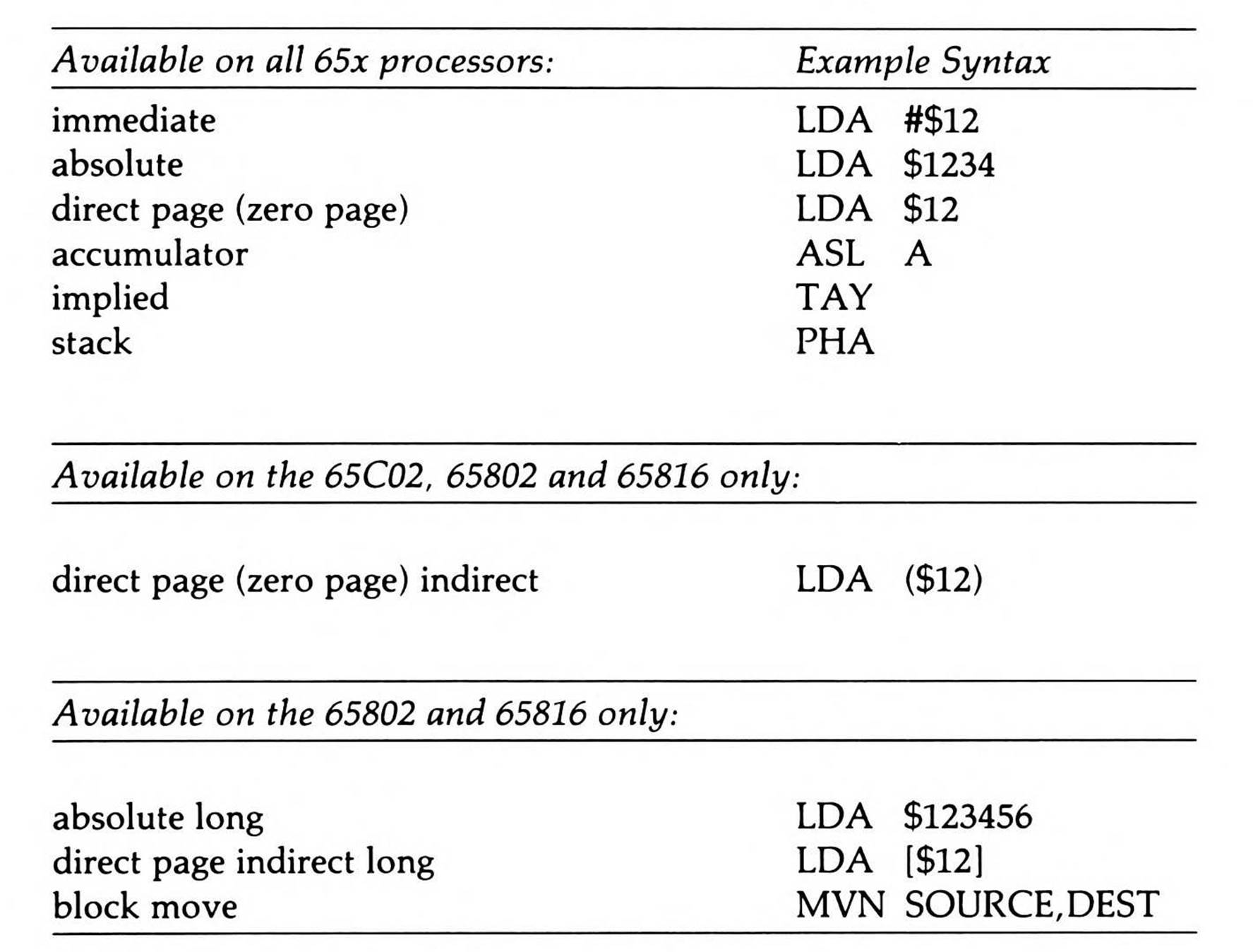
In addition to solving a given problem, the processor must spend a great deal of its time simply calculating effective addresses. The simple addressing modes require little or no effective address computation, and therefore tend to be the fastest executing. However, the problem-solving and memory efficiencies of the complex addressing modes, which will be described in subsequent chapters, can make up for their effective address calculation overhead. In each case, the nature of the problem at hand determines the best addressing mode to use.
Immediate Addressing
Immediate data is data found embedded in the instruction stream of a program itself, immediately following the opcode which uses the data. Because it is part of the program itself, it is always a constant value, known at assembly time and specified when you create the program. Typically, small amounts of constant data are handled most efficiently by using the immediate addressing mode to load either the accumulator or an index register with a specific value. Note that the immediate addressing mode is not available with any of the store instructions (STA,STX, or STY), since it makes no sense to store a value to the operand location within the code stream.
To specify the immediate addressing mode to a 65x assembler, prefix the operand with a # (pound or sharp) sign. The constant operand may be either data or an address.
For example,
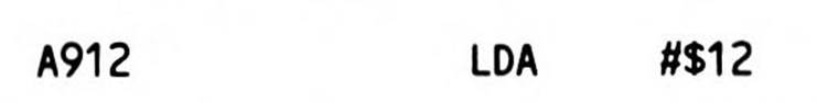
loads the hexadecimal value $12 into the accumulator.
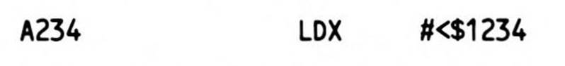
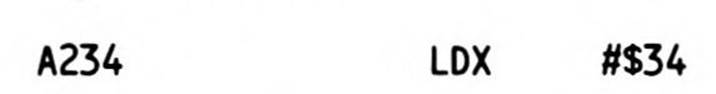
The 6502 and 65C02, their registers limited to only eight bits, permit only an eight-bit operand to follow the load register immediate opcodes. When the constant in an assembly source line is a sixteen-bit value, greater-than and less-than signs are used to specify whether the high- or low-order byte of the double-byte value are to be used. A less-than indicates that the low byte is to be used, and thus: causes the assembler to generate the LDX opcode followed by a one-byte operand, the low byte of the source operand, which is $34. It's equivalent to:
The use of a greater-than sign would cause the value $12 to be loaded. If neither the less-than nor greater-than operator is specified, most assemblers will default to the low byte when confronted with a double-byte value.
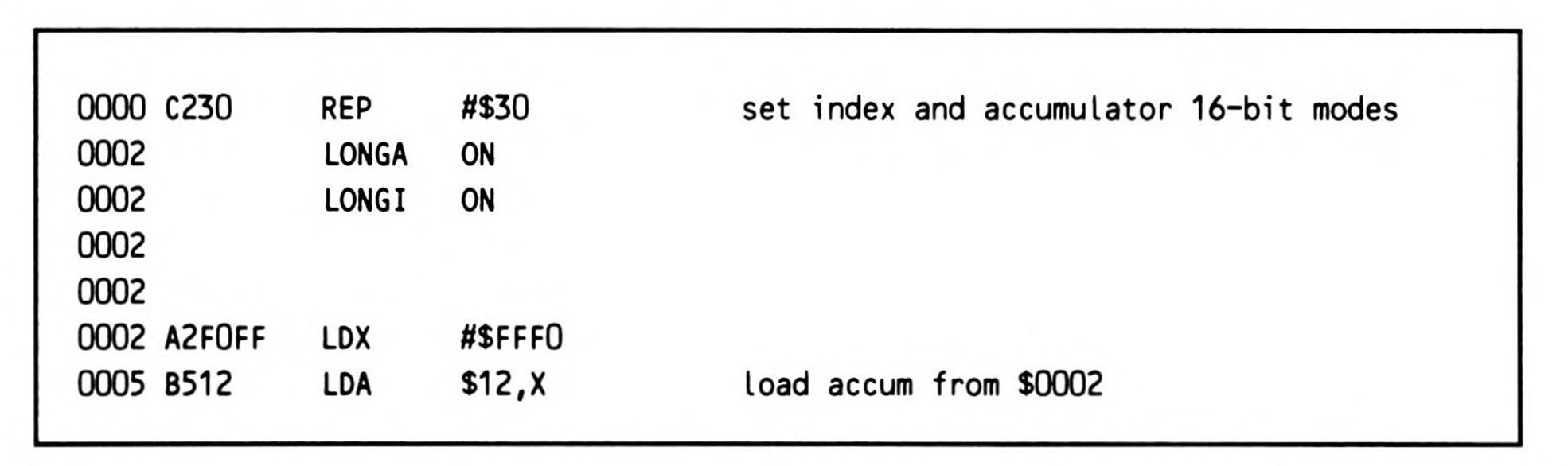
When assembling 65816 source code, the problem becomes trickier. The 6502 and 65C02 neither have nor need an instruction to set up the eight-bit mode because they are always in it. But the 65816's accumulator may be toggled to deal with either eight- or sixteen-bit quantities, as can its index registers, by setting or resetting the m (memory/accumulator select) or x (index select) flag bits of the status register. Setting the m bit puts the accumulator in eight-bit mode; resetting it puts it in sixteen-bit mode. Setting the x bit puts the index registers in eight-bit mode; resetting it puts them in sixteen-bit mode.
The m and x flags may be set and reset many times throughout a 65816 program. But while assembly code is assembled from beginning to end, it rarely executes in that fashion. More commonly, it follows a circuitous route of execution filled with branches, jumps, and subroutine calls. Except for right after the m or x flag has been explicitly set or reset, the assembler has no way of knowing the correct value of either: your program may branch somewhere, and reenter with either flag having either value, quite possibly an incorrect one.
While the programmer must always be aware of the proper values of these two flags, for most instructions the assembler doesn't need to know their status in order to generate code. Most instructions generated are the same in both eight- or sixteen-bit mode. Assembling a load accumulator absolute instruction, for example, puts the same opcode value and the same absolute address into the code stream regardless of accumulator size; it is at execution time that the m bit setting makes a difference between whether the accumulator is loaded with one or two bytes from the absolute address.
But a load register immediate instruction is followed by the constant to be loaded. As Figure 7.1 shows, if the register is set to eight-bit mode at the point the instruction is encountered, the 65816 expects a one-byte constant to follow before it fetches the next opcode. On the other hand, if the register is set to sixteen-bit mode at the point the instruction is encountered, the 65816 expects a double-byte constant to follow before it fetches the next opcode. The assembler must put either a one-byte or two-byte constant operand into the code following the load register immediate opcode based on the status of a flag which it doesn't know.
Immediate Addressing: 8 bits vs. 16
8 -Bit Data (all processors): Data: Operand byte.
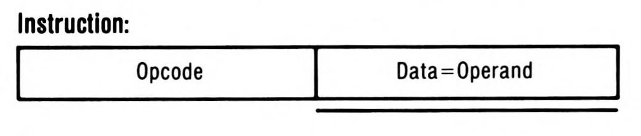
16-Bit Data (65802/65816. native mode, applicable mode flag m or x = 0):
Data High: Second operand byte.
Data Low : First operand byte.
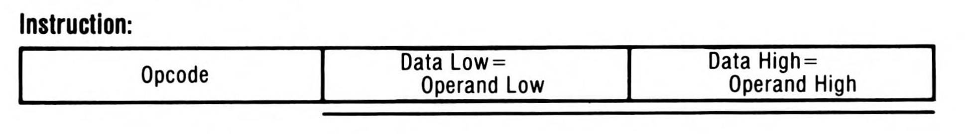
Figure 7.1. Immediate Addressing: 8 vs. 16 bits.
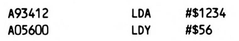
Two assembler directives have been designed to tell the assembler which way to go: LONGA and LONGI, each followed with the value ON or OFF. LONGA ON indicates the accumulator is in sixteen-bit mode, LONGA OFF in eight-bit mode. LONGI ON tells the assembler that the index registers are in sixteen-bit mode, LONGI OFF that they are in eight-bit mode. Load register immediate instructions are assembled on the basis of the last LONGA or LONGI directive the assembler has seen—that is, the one most immediately preceding it in the source file. For example, tells the assembler that both accumulator and index registers are set to sixteen bits. Now, if it next encounters the following two instructions then the first puts a LDA immediate opcode followed by the constant $1234 into the code, and the second a LDY immediate opcode followed by the constant $0056, again two bytes of operand, the high byte padded with zero.
|
LONGA |
ON |
|
LONGI |
ON |
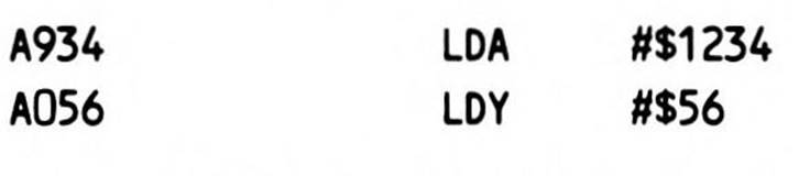
On the other hand, tells the assembler that both accumulator and index registers are set to eight bits. Now, puts a LDA immediate opcode followed by the constant $34 into the code, and the second a LDY immediate opcode followed by the constant $56, each one byte of operand.
|
LONGA |
OFF |
|
LONGI |
OFF |
Like the flags themselves, of course, one directive may be ON and the other OFF at any time. They also do not need to both be specified at the same time.
The settings of the LONGA and LONGI directives to either ON or OFF simply represent a promise by you, the programmer, that the flags will, in fact, have these values at execution time. The directives do nothing by themselves to change the settings of the actual m and xflags; this is typically done by using the SEP and REP instructions, explained earlier. (Note, incidentally, that these two instructions use a special form of the immediate addressing mode, where the operand is always eight bits.) Nor does setting the flags change the settings of the directives. You must therefore exercise caution to set the LONGA and LONGI flags to correctly represent the settings of the m and x flags, and to be sure never to branch into the code with the m or x flag set differently. If, for example, the assembler generated a LDA #$1234 instruction with LONGAset ON, only to have the m accumulator flag set to eight bits when the code is executed, the processor would load the accumulator with $34, then see the $12 which follows as the next opcode and try to execute it, resulting in program failure.
Absolute Addressing
There are two categories of simple addressing modes available for accessing data in a known memory location: absolute and direct page. The first of these, absolute addressing, is used to load or store a byte to or from a fixed memory location (within the current 64K data bank on the 65816, which defaults to bank zero on power up). You specify the sixteen-bit memory location in the operand field (following the opcode) in your assembly language source line, as Figure 7.2 shows.
For example, Fragment 7.1 loads the eight-bit constant $34 into the accumulator, then stores it to memory location $B100 in the current data bank.
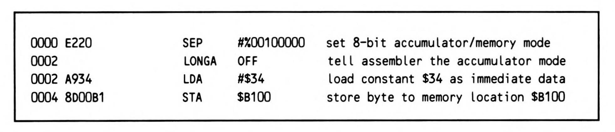
Fragment 7.1.
The same memory move could be done with either of the index registers, as shown in Fragment 7.2 using the X register. Symbolic labels in the operand fields provide better self-documentation and easier program modification.
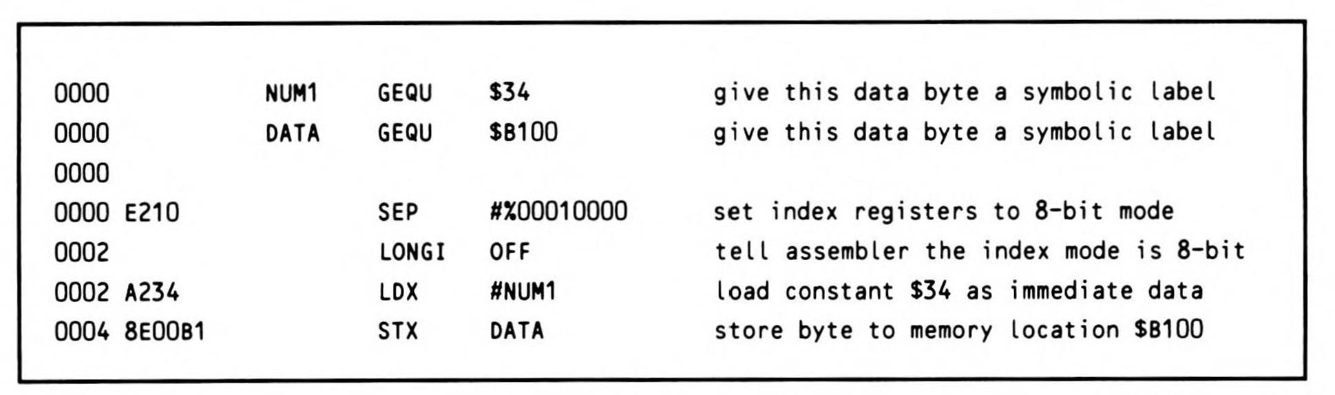
Fragment 7.2.
As you have seen, the 65816's accumulator may be toggled to deal with either eight- or sixteen-bit quantities, as can its index registers, by setting or resetting the m or x flag bits of the status register. Naturally, you don't need to execute a SEP or REP instruction nor a LONGAor LONGI assembler directive before every routine, provided you know the register you intend to use is already set correctly, and the assembler correctly knows that setting. But you must always exercise extreme care when developing 65816 programs to avoid making invalid assumptions about the modes currently in force or taking unintentional branches from code in one mode to code in another.
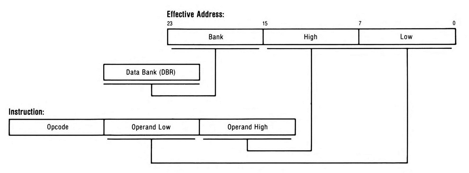
Figure 7.2. Absolute Addressing.
As Fragment 7.3 shows, the load and store instructions above will as easily move sixteen bits of data as they did eight bits; all that's needed is to be sure the register used is in sixteen-bit mode, and that the assembler has been alerted to the setting.
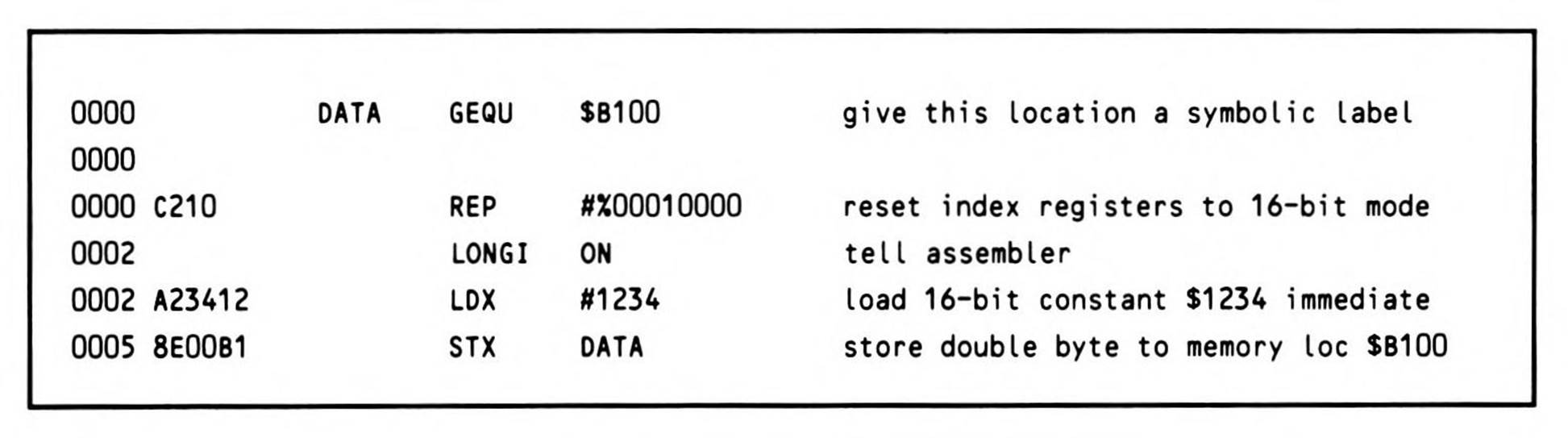
Fragment 7.3.
As indicated, absolute addresses are sixteen-bit addresses. On the 6502, 65C02, and 65802, with memory space limited to 64K, sixteen bits can specify any fixed location within the entire address space of the processor. Therefore, the term absolute addressing was appropriate.
The 65816, on the other hand, with its segmentation into 256 possible 64K banks, requires a 24-bit address to specify any fixed location within its address space. However, the same opcodes that generated sixteen-bit absolute addresses on the 6502 and 65C02 generate 24-bit addresses on the 65816 by concatenating the value of the data bank register with the sixteen-bit value in the operand field of the instruction. (Instructions that transfer control, to be discussed in Chapter 8, substitute the program bank register value for the data bank register value.)
Absolute addressing on the 65816 is therefore actually an offset from the base of the current bank; nevertheless, the use of the term absolute addressing has survived on the 65816 to refer to sixteen-bit fixed addresses within the current 64K data bank.
So long as the programmer needs to access only the contents of the current data bank, (sixteen-bit) absolute addressing is the best way to access data at any known location in that bank.
Direct Page Addressing
One of the most powerful and useful features of the 6502 and 65C02 processors is their zero page addressing modes. A page of memory on a 65x processor consists of 256 memory locations, starting at an address which is an integer multiple of $100 hexadecimal, that is, $0000, $0100, $0200, and so on. Generally, pages are numbered in hexadecimal, so their range within a 64K bank is $00 through $FF. Zero page addressing is made even more powerful and generalized as direct page addressing on the 65802 and 65816.
The zero page is the first of the 256 pages found within the 64K address space of the 6502 and 65C02—memory addresses $0000 to $00FF. These addresses may be accessed one byte cheaper than absolute memory accesses. Whereas loading or storing data from an absolute location will require three bytes of code, loading or storing a byte from a zero page location requires only two bytes, as Figure 7.3 shows.
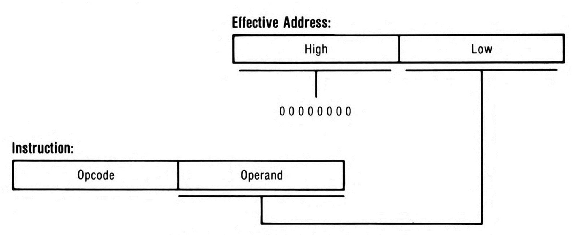
Figure 7.3. Zero Page Addressing.
Since all of the addresses in the zero page are less than $0100 (such as $003F, for example) it follows that, if the computer knew enough to assume two leading hexadecimal zeroes, a zero page address could be represented in only one byte, saving both space and time. But if absolute addressing is used, the processor has to assume that two bytes follow an instruction to represent the operand, regardless of whether the high-order byte is zero or not.
This concept of expressing a zero page address with a single-byte operand was implemented on the 6502 and 65C02 by reserving separate opcodes for the various instructions using zero page addressing. Since an instruction's opcode for using zero page addressing is unique (as opcodes are for all of the different addressing modes of a given instruction), the processor will fetch only one operand byte from the code stream, using it in effect as a displacement from a known base ($0000, in the case of the 6502 and 65C02). Since only one byte need be fetched from the instruction stream to determine the effective address, the execution time is faster by one cycle. The result is a form of addressing that is shorter, both in memory use and execution time, than regular sixteen-bit absolute addressing.
Clearly, locating your most often accessed variables in zero page memory results in considerably shorter code and faster execution time.
The limitation of having this special area of memory available to the zero page addressing mode instructions is that there are only 256 bytes of memory available for use in connection with it. That is, there are only 256 zero page addresses. Resident system programs, such as operating systems and language interpreters, typically grab large chunks of page zero for their own variable space; applications programmers must carefully step around the operating system's variables, limiting assignment of their own program's zero page variables to some fraction of the zero page.
This problem is overcome on the 65816 by letting its direct page be set up anywhere within the first 64K of system memory (bank zero), under program control. No longer limited to page zero, it is referred to as direct page addressing. The result is, potentially, multiple areas of 256 ($100) bytes each, which can be accessed one byte and one cycle cheaper than absolute memory. Setting the direct page anywhere is made possible by the 65816's direct page register, which serves as the base pointer for the direct page area of memory. Expressed in terms of the 65816's direct page concept, it can be said that on the 6502 (and 65C02), the direct page is fixed in memory to be the zero page.
So 6502 and 65C02 zero page addressing opcodes become direct page opcodes on the 65802 and 65816; and when they are executed, the "zero page address”—the single byte that the processor fetches immediately after the opcode fetch—becomes instead a direct page offset. This means that instead of simply pointing to a location in the range $0000 to $00FF as it would on the 6502 and 65C02, the direct page offset is added to the sixteen-bit value in the direct page register to form the effective direct page address, which can be anywhere in the range $00:0000 to $00:FFFF.
For purposes of this chapter, however, the discussion of direct page addressing will be limited to the default case, where the value in the direct page register is zero, making it functionally identical to the 6502 and 65C02 zero page addressing mode. Since it requires the effective address to be computed, relocation of the direct page will be considered as a form of complex addressing, and will be covered in future chapters. While "direct page offset" is more correct, it is also more abstract; the term direct page address is most commonly used. However, it is essential to remember that it is, in fact, an offset relative to a previously established direct page value (again, as used in this chapter, $0000).
An example of the use of direct page addressing to store a constant value to memory is as follows:
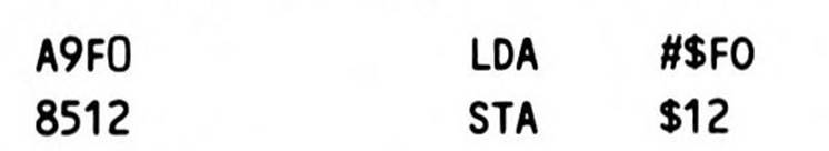
This stores the one-byte value $F0 at address $0012. Note that the object code generated for the store requires only one byte for the opcode and one for operand.
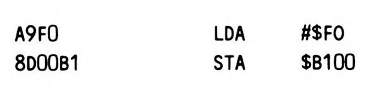
stores the same one-byte value at the address $B100. In this case, the store requires one byte for the opcode and two bytes for the operand.
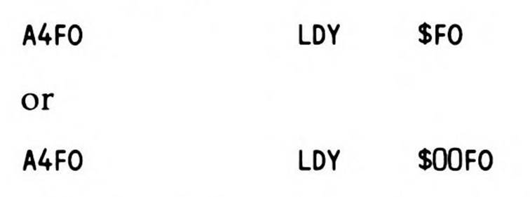
Notice how the assembler automatically assumes that if the value of the operand can be expressed in eight bits—if it is a value less than $100, whether coded as $34 or $0034 or $000034—the address is a direct page address. It therefore generates the opcode for the direct page addressing form of the instruction, and puts only a one-byte operand into the object code. For example, in the first of the two examples above, the direct page address to store to is $12. One result of the assembler's assumption that values less than $100 are direct page offsets is that physical addresses in the range $xx:0000 to $xx:00FF cannot be referenced normally when either the bank (the "xx") register is other than zero or the direct page register is set to other than $0000. For example, assembler syntax like:
is direct page syntax. It will not access absolute address direct page register holds a value other than zero; nor will it access $00F0 in another bank, even if the data bank register is set to the other bank. Both are evaluated to the same $F0 offset in the direct page. Instead, to access physical address $xx:00F0, you must force absolute addressing by using the vertical bar or exclamation point in your assembler source line:

Indexing
An array is a table or list in memory of sequentially stored data items of the same type and size. Accessing any particular item of data in an array requires that you specify both the location of the base of the array and the item number within the array. Either your program or the processor must translate the item number into the byte number within the array (they are the same if the items are bytes) and add it to the base location to find the address of the item to be accessed (see Figure 7.4).
Sometimes an array might be a table of addresses, either of data to be accessed or of the locations of routines to be executed. In this case, the size of each item is two bytes; the first address is at locations zero and one within the array, the second at locations two and three, the third at locations four and five, and so on. You must double the item number, resulting in the values 0, 2, 4, . . . from the array indices 0, 1, 2, . . ., and so on, to create an index into this array of two-byte data items.
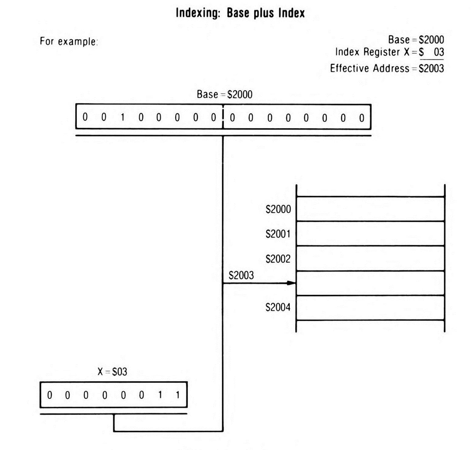
Figure 7.4. Indexing.
The 65x processors provide a wide range of indexed addressing modes that provide automatic indexing capability. In all of them, a value in one of the two index registers specifies the unsigned (positive integer) index into the array, while the instruction's operand specifies either the base of the array or a pointer to an indirect address at which the base may be found. Each addressing mode has a special operand field syntax for specifying the addressing mode to the assembler. It selects the opcode that will correctly instruct the processor where to find both the base and index.
Some early processors (the 6800, for example) had only one index register; moving data from one array to another required saving off the first index and loading the second before accessing the second array, then incrementing the second index and saving it before reloading the first index to again access the first array. The 65x processors were designed with two index registers so data can be quickly moved from an array indexed by one to a second array indexed by the other.
Often, the index registers are used simultaneously as indexes and as counters within loops in which consecutive memory locations are accessed.
The 65802 and 65816 index registers can optionally specify sixteen-bit offsets into an array, rather than eight-bit offsets, if the x index register select flag is clear when an indexed addressing mode is encountered. This lets simple arrays and other structured data elements be as large as 64K.
On the 6502, 65C02, and 65802, if an index plus its base would exceed $FFFF, it wraps to continue from the beginning of the 64K bank zero; that is, when index is added to base, any carry out of the low-order sixteen bits is lost. (See Figure 7.5.)
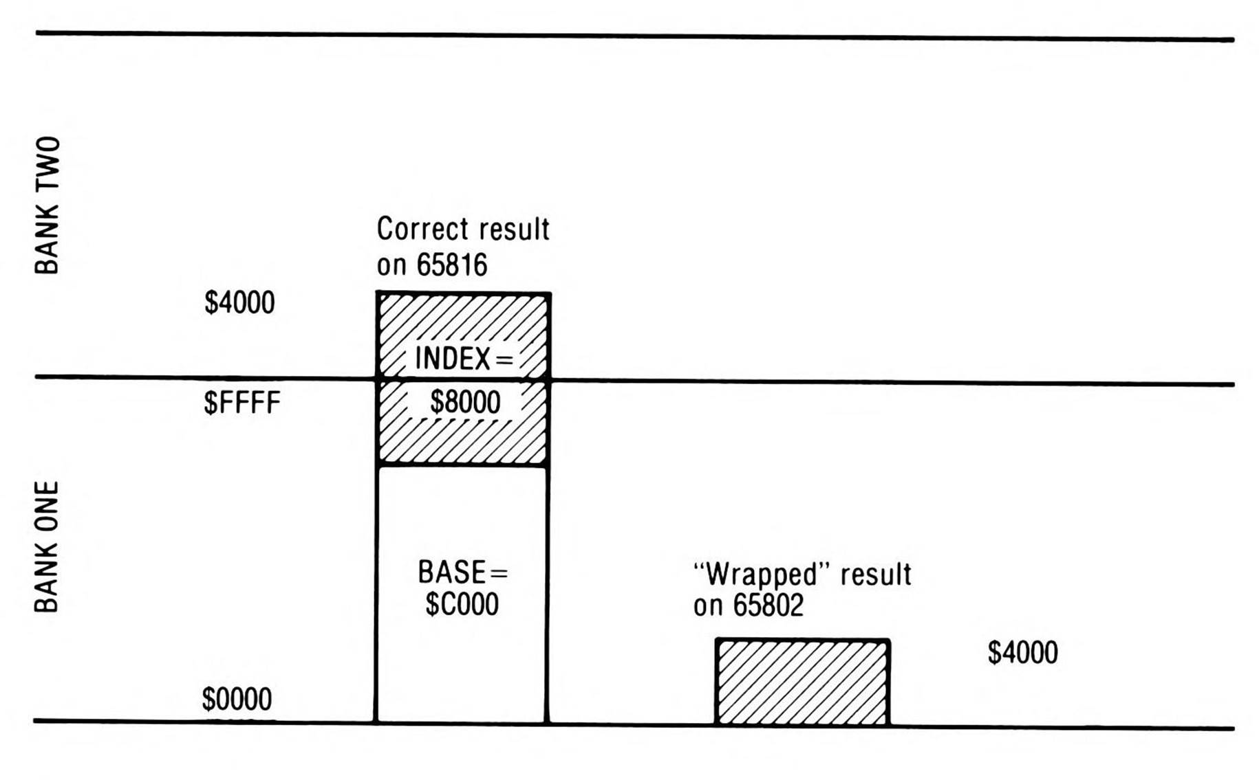
Figure 7.5. Indexing Beyond the End of the Bank.
On the 65816, the same is true of direct page indexing: because the direct page is always located in bank zero, any time the direct page, plus an offset into the direct page, plus an index exceeds $FFFF, the address wraps to remain in bank zero.
But as Figure 7.5 shows, whenever a 65816 base is specified by a 24-bit (long) address, or the base is specified by sixteen bits and assumes the data bank as its bank, then, if an index plus the low-order sixteen bits of its base exceeds $FFFF, it will temporarily (just for the current instruction) increment the bank. The 65816 assumes that the array being accessed extends into the next bank.
Absolute Indexed with X and Absolute Indexed with Y Addressing
Absolute addresses can be indexed with either the X (referred to as Absolute, X addressing) or the Y (referred to as Absolute, Y addressing) index register; but indexing with X is available to half again as many instructions as indexing with Y.
The base in these modes is specified by the operand, a sixteen-bit absolute address in the current data bank (Figure 7.6). The index is specified by the value in the X or Y register; the assembler picks the correct opcode on the basis of which index register the syntax specifies.
In Fragment 7.4, the X register is used to load the accumulator from $2200 plus 5, or $2205. If run on the 65816 in native mode, then if the accumulator is set to sixteen-bit mode, two bytes will be loaded from $2205 and $2206 in the current data bank.
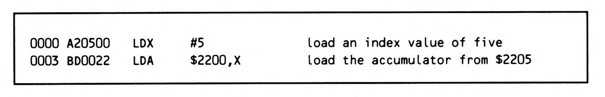
Fragment 7.4.
If the 65816 is in native mode and the index registers are set to sixteen-bit mode, indexes greater than $FF can be used, as Fragment 7.5 illustrates.
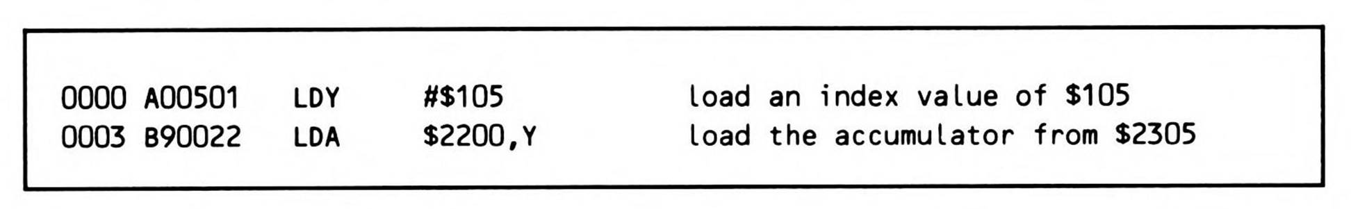
Fragment 7.5.
If the index register plus the constant base exceeds $FFFF, the result will continue beyond the end of the current 64K data bank into the next bank (the bank byte of the 24-bit address is temporarily incremented by one). So an array of any length (up to 64K bytes) can be started at any location and absolute indexed addressing will correctly index into the array, even across a bank boundary. 65802 arrays, however, wrap at the 64K boundary, since effectively there is only the single 64K bank zero.
Loading the index register with an immediate constant, as in the previous two examples, is of limited use: if, when writing a program, you know that you want to load the accumulator from $2305, you will generate far fewer bytes by using absolute addressing:
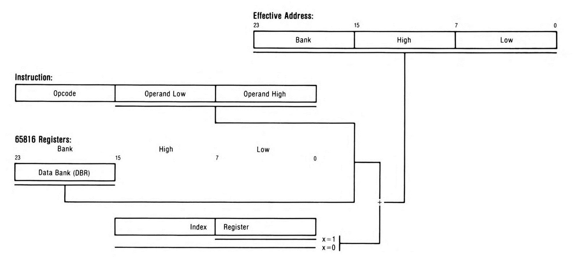
Figure 7.6. Absolute Indexing with a Generic Index Register.

The usefulness of indexed addressing becomes clear when you don't know, as you write a program, what the index into the array will be. Perhaps the program will select among indexes, or calculate one, or retrieve it from a variable, as in Fragment 7.6.
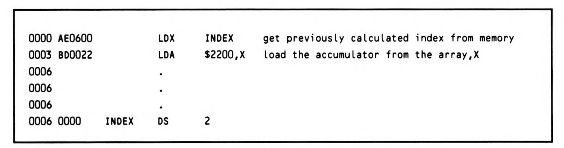
Fragment 7.6.
It can be useful to be able to put the base of an array into the index register and let it vary, while keeping the index into the array constant. This is seldom possible with the eight bits of the 6502's and 65C02's index registers, since they limit the base addresses they can hold to the zero page, but it is a useful capability of the 65802 and 65816.
For example, suppose, as in Fragment 7.7, you're dealing with dozens (or hundreds) of records in memory. You need to be able to update the fifth byte (which is a status field) of an arbitrary record. By loading the base address of the desired record into an index register, you can use a constant to access the status field. The index into the array, five, is fixed; the array base varies.
Because the index is less than $100, the assembler would normally generate direct page indexing. To force the assembler to generate absolute indexing, not direct page indexing, you must use the vertical bar (or exclamation point) in front of the five, as Fragment 7.7 shows. That way, the five is generated as the double-byte operand $0005, an absolute address to which the address in the index register is added to form the absolute effective address.
Had the Y index register been used instead of X in Fragment 7.7, the vertical bar would have been acceptable but not necessary; direct page,Y addressing, as you will learn in the next section, can only be used with the LDX and STX instructions, so the assembler would have been forced to use absolute, Y addressing regardless.
Both absolute, X and absolute, Y can be used by what are called the eight Group I instructions, the memory-to-accumulator instructions which can use more addressing modes than any others: LDA, STA, ADC, SBC, CMP, AND, ORA, and EOR. In addition, absolute, X can be used for shifting data in memory, incrementing and decrementing data in memory, loading the Y register, and for other instructions; but absolute, Y has only one other use—to load the X register.

Fragment 7.7.
Direct Page Indexed with X and Direct Page Indexed with y Addressing
Arrays based in the direct page (the zero page on the 6502 and 65C02) can be indexed with either the X1 register (called Direct Page,X addressing) or the Y register (called Direct Page,Y addressing). However, direct page,Y addressing is available only for the purpose of loading and storing the X register, while direct page,X is full-featured.
As is standard with indexed addressing modes, the index, which is specified by the index register, is added to the array base specified by the operand. Unlike the absolute indexed modes, the array always starts in the direct page. So the array base, a direct page offset, can be specified with a single byte. The sum of the base and the index, a direct page offset, must be added to the value in the direct page register to find its absolute address, as shown in Figure 7.7.
In Fragment 7.8, the accumulator is loaded from a direct page offset base of $32 plus index of $10, or an offset of $42 from the direct page register's setting.
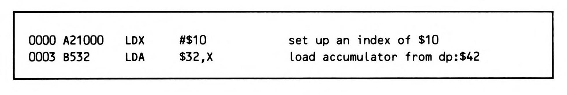
Fragment 7.8.
Remember that the effective address is an offset of $42 from the direct page register and is always in bank zero. It will correspond to an absolute address of $0042 only when the direct page register is equal to zero (the default here in this chapter). Chapter 11, which covers the complex addressing modes, details relocation of the direct page.
When the index registers are set to eight bits, you can code the index and the array base interchangeably—they are both the same size. So the index, if it is a constant, may be specified as the operand, with the array base in the index register. Using the last example, the $10 in the index register could be the direct page base of the array; the operand, $32, would then be the index into an array in the direct page which begins at the direct page offset $10.
On the 6502 and the 65C02, and in the 6502 emulation modes of the two sixteen-bit processors, indexing past the end of the direct page wraps to the beginning of the direct page, as Fragment 7.9 shows. The index and the direct page array base are added, but only the low eight bits of the sum specify the direct page offset of the effective address. So in Fragment 7.9, while the base of $32 plus the index of $F0 equals $122, only the $22 is kept, and the accumulator is loaded from dp:$22.
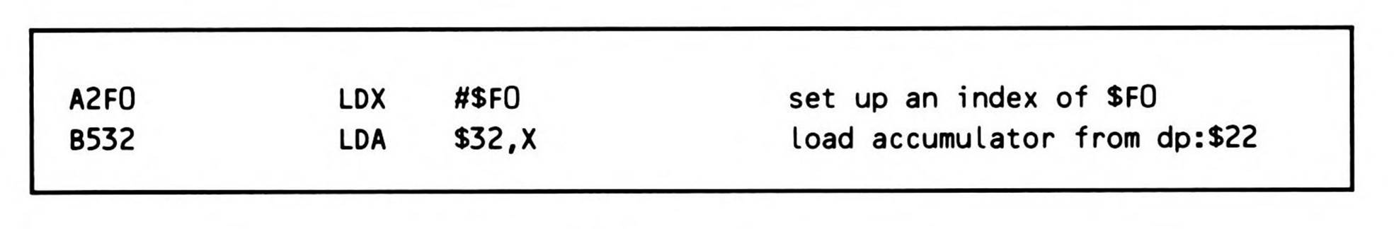
Fragment 7.9.
In 65802 and 65816 native mode, however, indexes can be sixteen bits, so direct page indexing was freed of the restriction that the effective address be within the direct page. Arrays always start in the direct page, but indexing past the end of the direct page extends on through bank zero, except that it wraps when the result is greater than $FFFF to remain in bank zero (unlike absolute indexing, which temporarily allows access into the next higher bank).
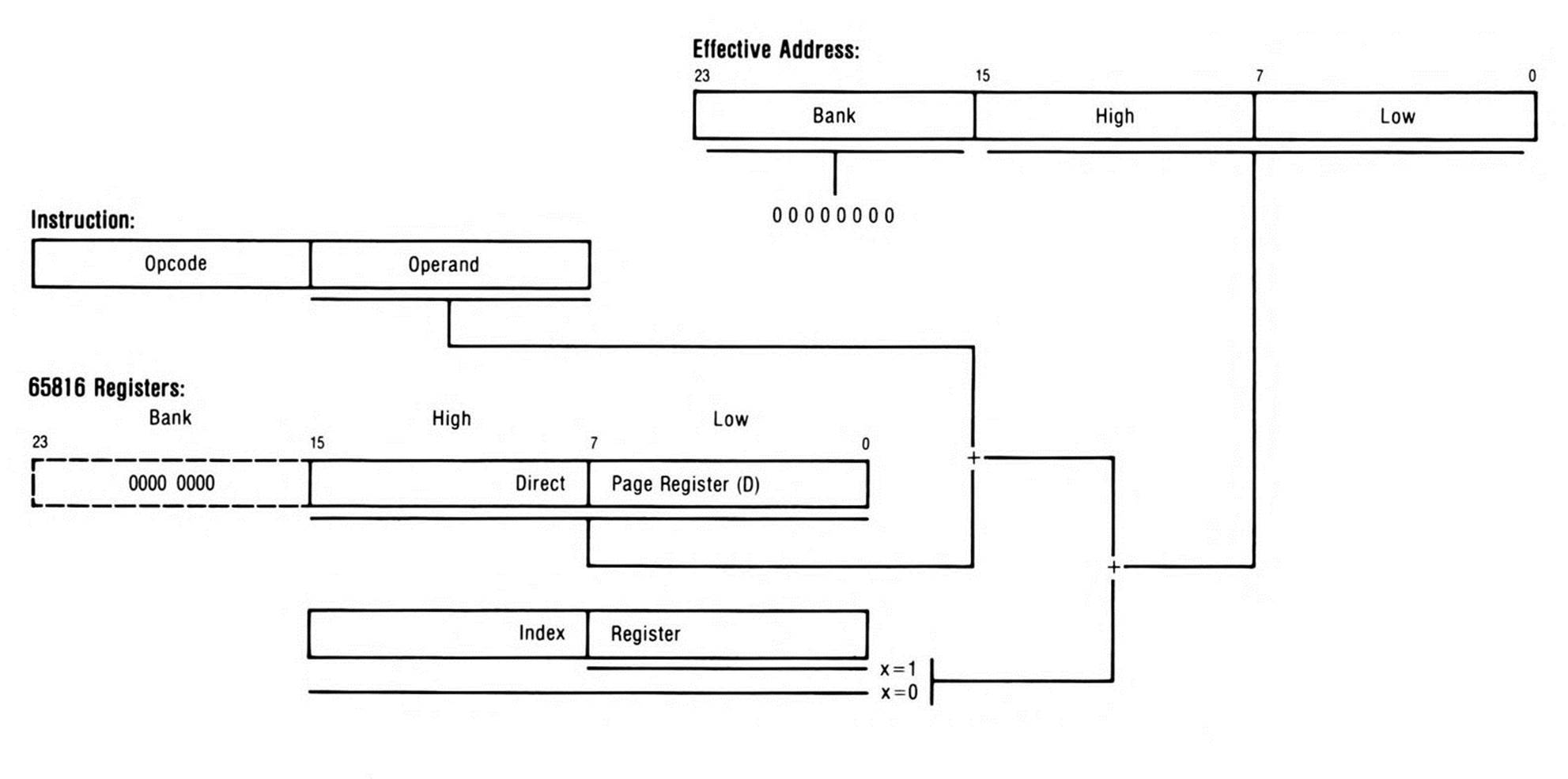
Figure 7.7. Direct Page Indexing with a Generic Index Register.
In Fragment 7.10, the accumulator is loaded from the value in the direct page register plus the direct page base of $12 plus index of $FFF0, or dp:$0002. Note this is in bank zero, not bank one.
Fragment 7.10.
If the index registers are set to sixteen bits and the array indexes you need to use are all known constants less than $100, then you can use direct page indexing to access arrays beginning, not just in the direct page, but anywhere in bank zero memory: load the index register with the sixteen-bit base of the array and specify the index into the array as the operand constant. This technique would generally only be useful if the direct page register has its default value of zero.
Accumulator Addressing
Accumulator addressing is only available for the read-modify-write instructions such as shifts and rotates. The instructions themselves will be explained in subsequent chapters, and the use of accumulator addressing with them will be reviewed in detail.
As a simple addressing mode, accumulator addressing is included in this chapter for the sake of completeness even though the instructions which use it have not yet been introduced.
Generally, most operations take place upon two operands, one of which is stored in the accumulator, the other in memory, with the result being stored in the accumulator. Read-modify-write instructions, such as the shifts and rotates, are "unary" operations; that is, they have only a single operand, which in the case of accumulator addressing, is located in the accumulator. There is no reference to external memory in the accumulator addressing modes. As usual, the result is stored in the accumulator.
The syntax for accumulator addressing, using the ASL (arithmetic shift left) instruction as an example, is:
Implied Addressing
In implied addressing, the operand of the instruction is implicit in the operation code itself; when the operand is a register, it is specified in the opcode's mnemonic. Implied operand instructions are therefore single-byte instructions consisting of opcode only, unlike instructions that reference external memory and as a result must have operands in subsequent bytes of the instruction.
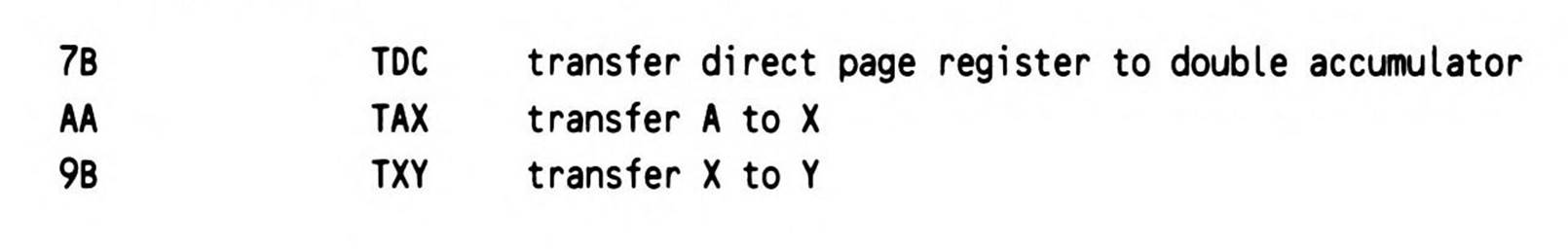
You have already encountered implied addressing in the previous chapter in the form of the register transfer instructions and exchanges. Since there are a small number of registers, it is possible to dedicate an opcode to each specific register transfer operation. Other instructions that use implied addressing are the register increments and decrements.
As one-byte instructions, there is no assembler operand field to be coded: You simply code the assembler mnemonic for the given instruction, as below:
Stack
Stack addressing references the memory location pointed to by the stack register. Typical use of the stack addressing mode is via the push and pull instructions, which add or remove data to or from the stack area of memory and which automatically decrement or increment the stack pointer. Examples of the use of push and pull instructions were given in the previous chapter.
Additionally, the stack is used by the jump to subroutine, return from subroutine, interrupt, and return from interrupt instructions to automatically store and retrieve return addresses and in some cases also the status register. This form of stack addressing will be covered inChapter 12, Subroutines, and Chapter 13, System Control.
The assembler syntax of the push and pull instructions is similar to that of implied instructions; no operand field is coded, since the operation will always access memory at the stack pointer location.
Direct Page Indirect Addressing
Direct page indirect addressing, or, as it is known on the 65C02, zero page indirect, is unavailable on the 6502; it was first introduced on the 65C02.
Indirect addressing was designed for the 65C02 as a simplification of two often-used complex forms of addressing available on the 6502 known as zero page indirect indexed and zero page indexed indirect addressing (these forms of addressing on the 65816 are of course direct page indirect indexed or indexed indirect addressing; they are explained in Chapter 11, Complex Addressing Modes). It was found that programmers were tolerating the overhead inherent in these two complex addressing modes to simulate simple indirection.
The concept of simple indirect addressing lies on the borderline between the simple and complex addressing modes. An understanding of it forms the basis for understanding several of the more complex indexed modes which use indirection as well.
An indirect address is an address stored in memory which points to the data to be accessed; it is located by means of the operand, an address which points to the indirect address, as shown in Figure 7.8. Except in the case of indirect jump instructions, explained in Chapter 8, Flow of Control, this pointer is always a direct page address.
The use of indirect addresses brings great flexibility to the addressing options available to you. There is, however, a penalty in execution speed, imposed by the fact that, in addition to the operand fetch from the code stream, the actual effective address must also be fetched from memory before the data itself can be accessed. For this reason, direct page addresses are used as the pointers to the indirect addresses since, as you will remember from the discussion of direct page addressing, the direct page offset itself can be determined with only a single memory fetch.
The syntax for indirect addressing is to enclose in parentheses, as the operand, the direct page pointer to the indirect address.
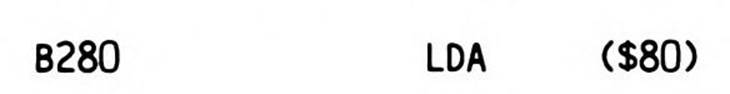
This means, as Figure 7.8 illustrates, "go to the direct page address $80 and fetch the absolute (sixteen-bit) address stored there, and then load the accumulator with the data at that address." The low-order byte of the indirect address is stored at dp:$80, the high-order byte at dp:$81—typical 65x low/high fashion. Remember, in the default case where DP equals $0000, the direct page address equals the zero page address, namely $00:0080.
As explained above, the indirect address stored at the direct page location (pointed to by the instruction operand) is a sixteen-bit address. The general rule for the 65816 is that when an addressing mode only specifies sixteen bits of the address, then the bank byte (bits 16-23) of the address is provided by the data bank register. This rule applies here; but you must first note that the direct page offset which points to the indirect address is itself always located in bank zero because the direct page itself is always located in bank zero. The examples, however, were simplified to assume both the data bank and the direct page register to be zero.
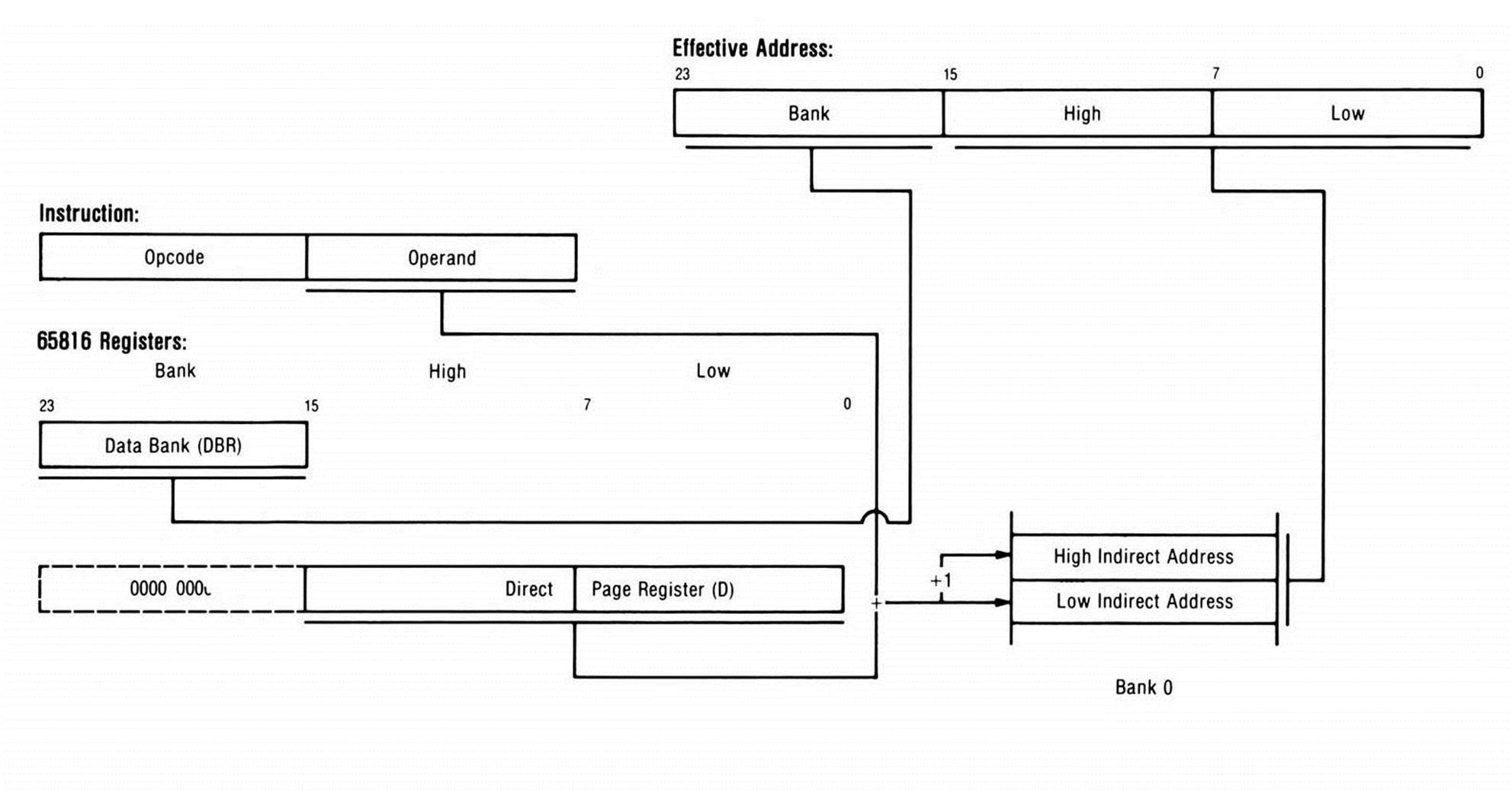
Figure 7.8. Direct Page Indirect Addressing.
The use of indirect addressing allows an address that is referenced numerous times throughout a routine and is subject to modification—for example, a pointer to a data region—to be modified in only one location and yet alter the effective address of many instructions.
In Listing 7.1, the data $1234 is moved from location VAR1 to VAR2. Note that the load and store instructions had the same operand: the symbol DPA, which had been given a value of $80. The indirect address stored at that location was different in each case, however, resulting in the data being copied from one location to another. While this example in itself is an inefficient way to move a double-byte word to another location, it does illustrate the basic method of indirect addressing, which will become quite useful as looping and counting instructions are added to your working set of 65x instructions.
Absolute Long Addressing
This is the first of the simple addressing modes that are available only on the 65816 and 65802 processors.
Absolute long addressing is an extension of (sixteen-bit) absolute addressing—that is, addressing at a known location. Remember that on the 6502 and 65C02, address space is limited to 64K, and any location within the entire memory range can be specified with a sixteen-bit address. This is not the case with the 65816, which can address up to sixteen megabytes of memory. Thus 24 bits are required to specify a given memory location.
In general, there are two ways by which a 24-bit data address is generated. In the case of sixteen-bit absolute addressing, a 64K memory context is defined by the value of the data bank register; the bank byte of the 24-bit address is derived directly from that register via simple concatenation (connecting together) of the data bank value and the sixteen-bit address. The alternative method is to specify a complete 24-bit effective address for a given instruction. The absolute long addressing mode is one of the means for doing this.
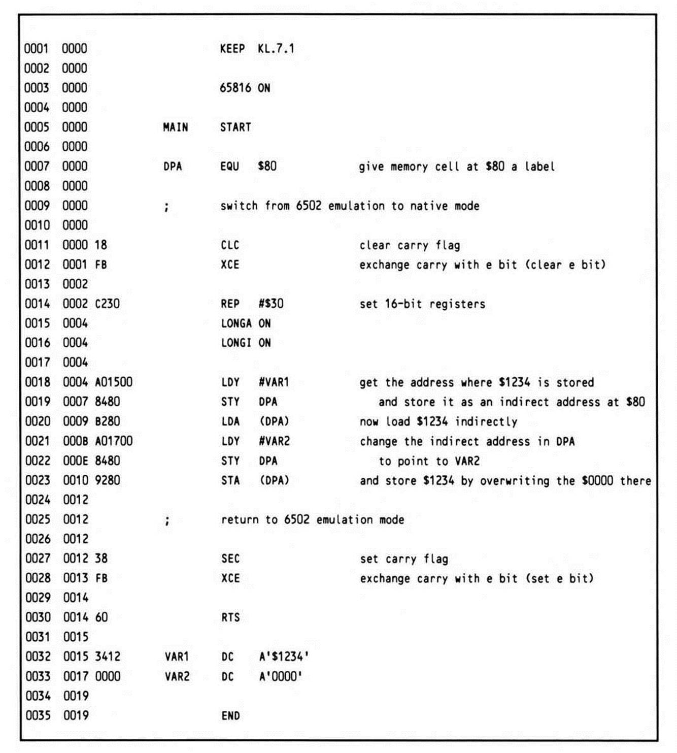
As the name should imply, this addressing mode specifies a known, fixed location within the sixteen-megabyte addressing space of the 65816, just as sixteen-bit absolute addressing specifies a known, fixed location within either the 64K space of the 6502, 65C02, or 65802, or else the 64K data space determined by the 65816's data bank register. Just as the sixteen-bit absolute addressing operations are three-byte instructions, consisting of opcode, address low, and address high, the instructions that use the 24-bit absolute long addressing mode are four-byte instructions, comprised of opcode, low byte of address, high byte of address, and bank byte of address, as shown in Figure 7.9. The value in bits 8-15 of the effective address is described as the high byte, and 16-23 as the bank byte, because this most clearly reflects both the parallels with the 6502 and 65C02 and the bank-oriented memory segmentation of the 65816 architecture.
Listing 7.1.
When absolute long addressing is used, the bank address in the operand of the instruction temporarily overrides the value in the data bank register for the duration of a single instruction. Thus, it is possible to directly address any memory location within the entire sixteen-megabyte address space.
You will likely find, however, that this form of addressing is one of the less frequently used. There are two reasons for this: first, it is more efficient to use the shorter sixteen-bit addressing modes, provided that the data bank register has been appropriately set; second, it is generally undesirable to hard code fixed 24-bit addresses into an application, as this tends to make the application dependent on being run in a fixed location within a fixed bank. (An exception to this is the case where the address referenced is an I/O location, which is fixed by the given system hardware configuration.)
The 65x processors, in general, do not lend themselves to writing entirely position-independent code, although the 65816 certainly eases this task compared to the 6502 and 65C02. There is, however, no reason why code should not be written on the 65816 and 65802 to bebank-independent—that is, capable of being executed from an arbitrary memory bank. But using absolute long addressing will tend to make this difficult if not impossible.
If you are using a 65802 in an existing system, it is important to note that although the address space of the 65802 is limited to 64K at the hardware level, internally the processor still works with 24-bit addresses. One thing this means is that it is legal to use the long addressing modes such as absolute long. But using them is futile, even wasteful: an extra address byte is required for the bank, but the bank address generated is ignored. There are cases where use of forms of long addressing other than absolute long should be used if you are targeting your code for both the 65802 and the 65816. But generally there is little reason to use the absolute long addressing mode on the 65802, except perhaps for fine-tuning a timing loop (the absolute long addressing mode requires an extra cycle to execute in order to fetch the bank address in the fourth byte of the instruction).
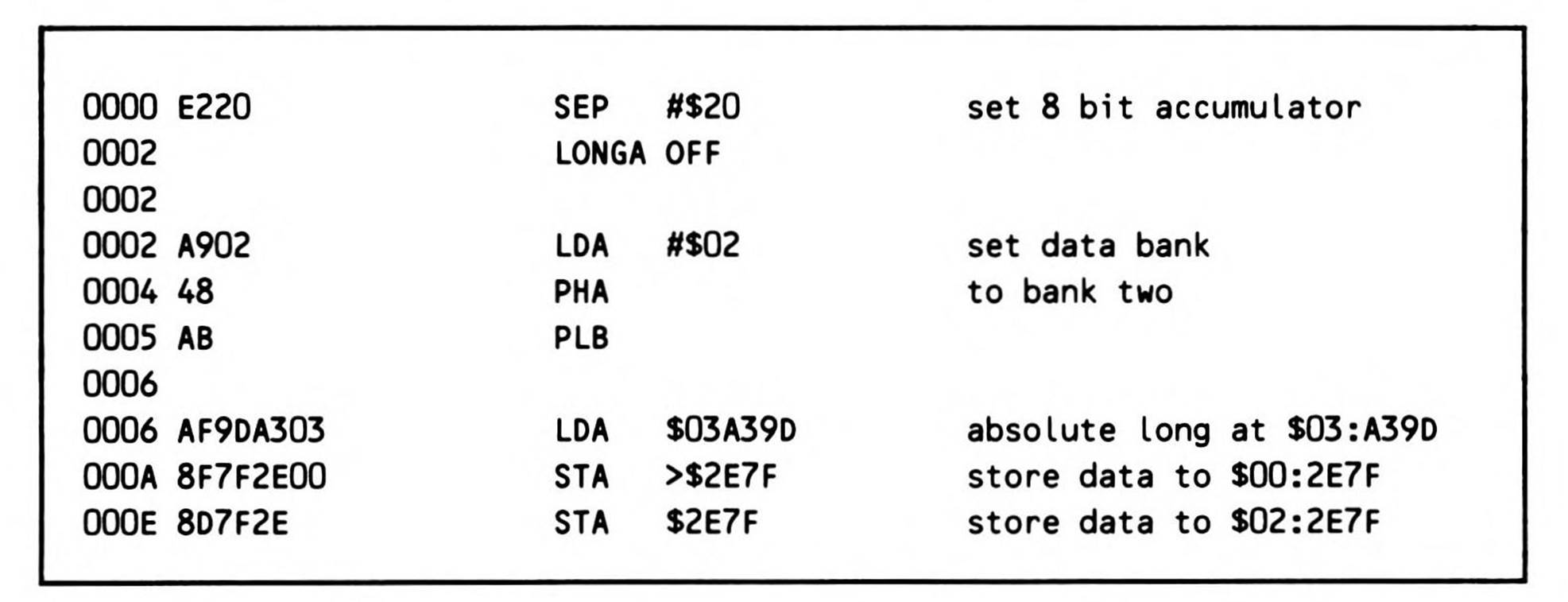
The assembler syntax to indicate the absolute long addressing mode is simply to code a value in the operand field greater than $FFFF. To force long addressing for bank zero addresses ($00:0000 to $00:FFFF), use the greater-than sign (>) as a prefix to the operand (similar to the use of the vertical bar to force sixteen-bit absolute addressing) as shown in Fragment 7.11.
Note that the first STA instruction in Fragment 7.11 generates a four-byte instruction to store the accumulator to a bank zero address, while the second STA instruction generates a three-byte instruction to store the accumulator to the same sixteen-bit displacement but within bank two, the current data bank. Also note that for both the load and the first store instructions, absolute long addressing causes the current data bank register, which is set to two, to be overridden.
Figure 7.9. Absolute Long Addressing.
Fragment 7.11.
Absolute Long Indexed with X Addressing
Absolute long indexed with X, or absolute long indexed, uses the X register for its index, and an absolute long address as its base. It lets you index into an array located in a bank other than the data bank.
Instructions using absolute long indexed addressing are four bytes in length, since three bytes are needed to express 24-bit absolute-long operands. The bank byte, being the highest byte in the operand, is the fourth byte of the instruction. The contents of the X index register are added to the absolute-long operand to form the 24-bit effective address at which data will be accessed.
For example, Fragment 7.12 gets a character from a text buffer starting at $3000 in bank zero and stores it into buffers starting at $1000 in bank two and at $E000 in bank three. Because the character to be loaded is in bank zero, its long address is expressed in sixteen bits. You must preface a reference to it with the greater-than sign to override the assembler assumption that a sixteen-bit operand is in the data bank, and force the assembler to instead use long addressing. The next instruction stores to the data bank, requiring only absolute indexing; the assembler assumes simple sixteen-bit operands are located in the data bank. Finally, storing into bank three requires no special specification: since $03E000 cannot be expressed in sixteen bits, long addressing is assumed.
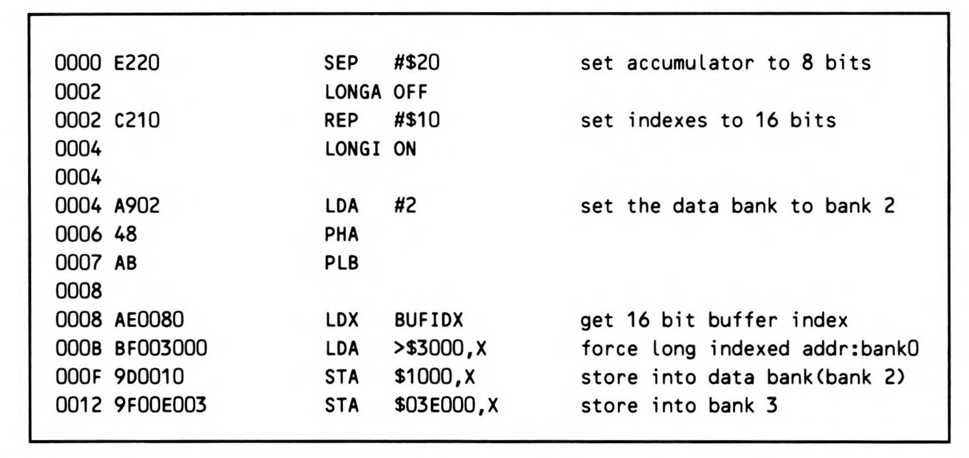
Fragment 7.12.
Direct Page Indirect Long
Direct page indirect long is another case of long (24-bit) addressing, where the effective address generated temporarily overrides the current value in the data bank register. Unlike the previous two long addressing modes, however, the 24-bit address is not contained in the operand itself. The instruction is two bytes long, much like regular direct page indirect addressing. The operand of the instruction is, like its non-long counterpart, a direct page offset acting as an indirect pointer; the difference in this case is that rather than pointing to a sixteen-bit address in the data bank, it points to a 24-bit address. If, for example, the direct page address is $80, as in Figure 7.10, the processor will fetch the low byte of the effective address from dp:$80, the high byte from dp:$81, and the bank byte from dp:$82. The bank byte temporarily overrides the value in the data bank register.
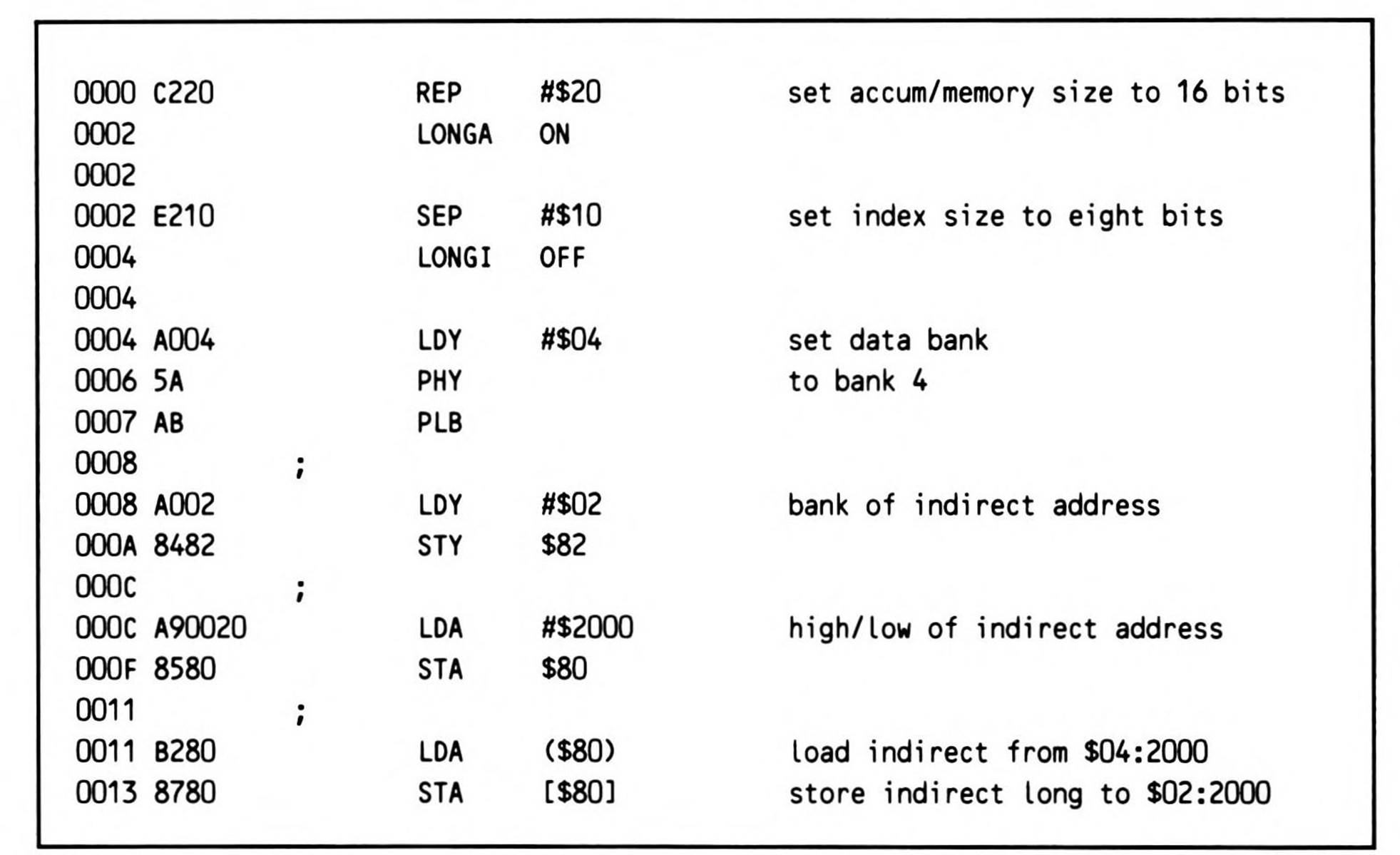
Fragment 7.13 shows the use of both direct page indirect addressing and direct page indirect long, using the latter to access the data as set up in Figure 7.10. The syntax for indirect long addressing is similar to that for direct page indirect, except left and right square brackets rather than parentheses enclose the direct page address to indicate the indirect address is long.
In this example, a sixteen-bit accumulator size is used with eight-bit index registers. The simultaneous availability of both an eight-bit and a sixteen-bit register in this mode simplifies the manipulation of long addresses. First, a value of $04 is loaded into the eight-bit Y register using immediate addressing. Since the LONGI OFF directive has been coded, the assembler automatically generates an eight-bit operand for this instruction. This is pushed onto the stack, and then pulled into the bank register. Next, Y is loaded with #$02, the bank component of the indirect long address, which is stored to dp:$82. The sixteen-bit accumulator is then used to load an immediate $2000 (high/low of the indirect and the indirect long addresses), which is stored at dp:$80. This results in the following values in memory: at dp:$80 is $00, at dp:$81 is $20, and at dp:$82 is $02. The data bank register contains $04. The memory at locations dp:$80.81 contains the indirect address $2000, while the memory at locations dp:$80.82 contains the indirect long address $02:2000. The load indirect instruction uses the data bank register to form the bank address, and so loads double-byte data from $04:2000. The store indirect long stores the double-byte data at $02:2000. The overlapping of the low and high bytes of the indirect address in locations dp:$80 and dp:$81 highlights the difference in the source of the bank byte using the two addressing modes.
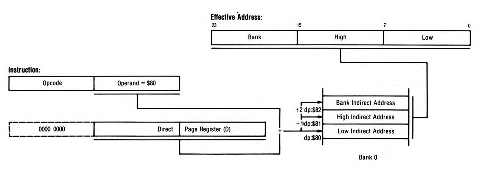
Figure 7.10. Direct Page Indirect Long Addressing.
Fragment 7.13.
Block Move
Block move addressing is a dedicated addressing mode, available only for two instructions, MVN and MVP, which have no other addressing modes available to them. These operations were explained in the previous chapter.
All materials on the site are licensed Creative Commons Attribution-Sharealike 3.0 Unported CC BY-SA 3.0 & GNU Free Documentation License (GFDL)
If you are the copyright holder of any material contained on our site and intend to remove it, please contact our site administrator for approval.
© 2016-2026 All site design rights belong to S.Y.A.