Programming the 65816 Including the 6502, 65C02, and 65802 (1986)
Part III. Tutorial
11. The Complex Addressing Modes
Chapter 7 defined the term addressing mode and introduced the set of simple 65x addressing modes, those which involve at most a minimum of calculating combined values from multiple locations.
This chapter continues and expands the discussion of one of those modes, the direct page addressing mode, for those cases where the direct page register value is other than zero. It discusses the basis for selection by the assembler among the direct page, absolute, and long addressing modes, and how you can explicitly override those assumptions. And it discusses the set of complex addressing modes available on the 6502, the 65C02, the 65802, and the 65816, those which require the effective address to be calculated from several sources (Table 11.1). The understanding of these modes also provides the context within which to discuss several more complex push instructions that were previously deferred to this chapter (Table 11.2).
Table 11.1. Complex Addressing Modes.
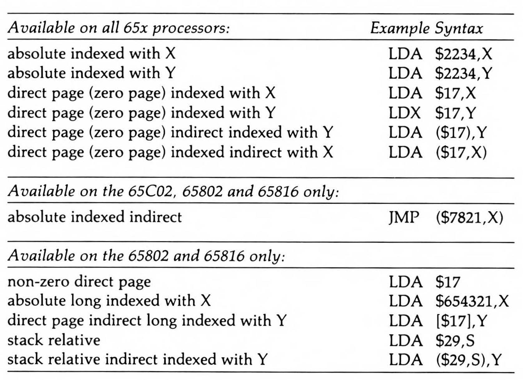
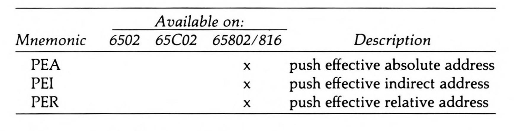
Table 11.2. Complex Push Instructions.
Relocating the Direct Page
Chapter 7 discussed zero page addressing as found on the 6502 and 65C02 and introduced direct page addressing, the 65816's enhancement to zero page addressing. The 65816 lets the zero page addressing modes use a direct page that can be located and relocated anywhere in the first 64K of memory. But Chapter 7 left the direct page set to page zero so it could be discussed as a simple addressing mode—that is, so no calculation of direct page register base plus direct page offset needed to be done and so the operand, a direct page offset, could be thought of as an absolute address with a high-order byte of zero.
Relocating the direct page from page zero, to which it is initialized on power-up, can be accomplished in either of two ways. The first would let a new value be pulled off the stack into the direct page register with the PLD instruction, as found in Fragment 11.1.
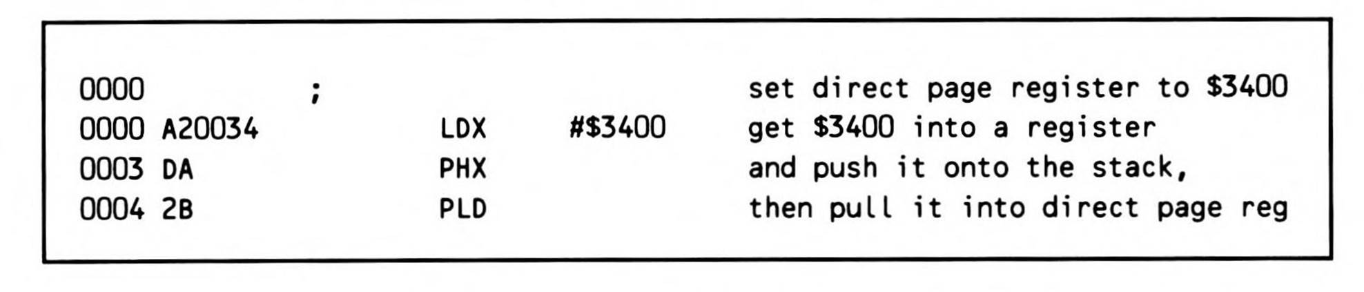
Fragment 11.1.
Fragment 11.2 illustrates the second method. The direct page register can be set to the value in the sixteen-bit C accumulator by use of the TCD instruction, which transfers sixteen bits from accumulator to direct page register.
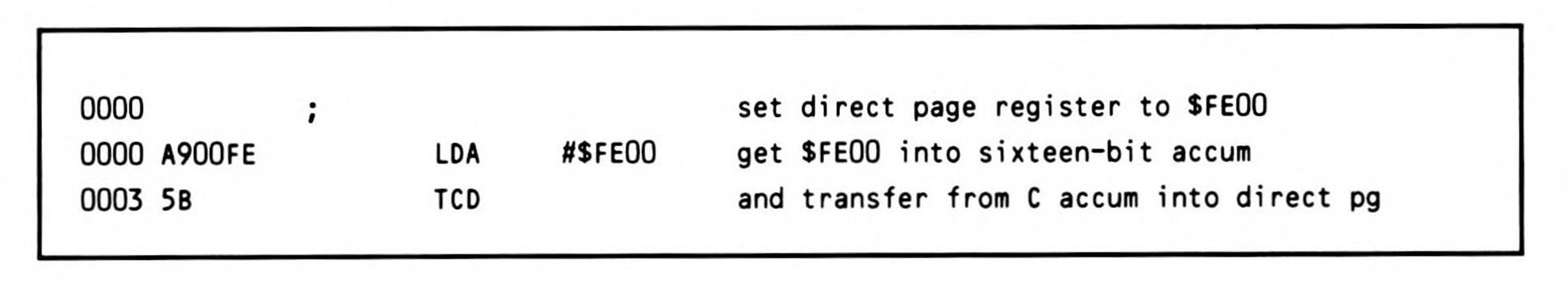
Fragment 11.2.
Both methods of setting the direct page register give it a sixteen-bit value. Since sixteen bits are only capable of specifying an address within a 64K range, its bank component must be provided in another manner; this has been done by limiting the direct page to bank zero. The direct page can be located anywhere in 64K but the bank address of the direct page is always bank zero.
Chapter 7, which limited the use of the direct page to page zero, used the example shown in Fragment 11.3 to store the one-byte value $F0 at address $0012, which is the direct page offset of $12 added to a direct page register value of zero. If instead the direct page register is set to $FE00, then $F0 is stored to $FE12; the direct page offset of $12 is added to the direct page register value of $FE00.
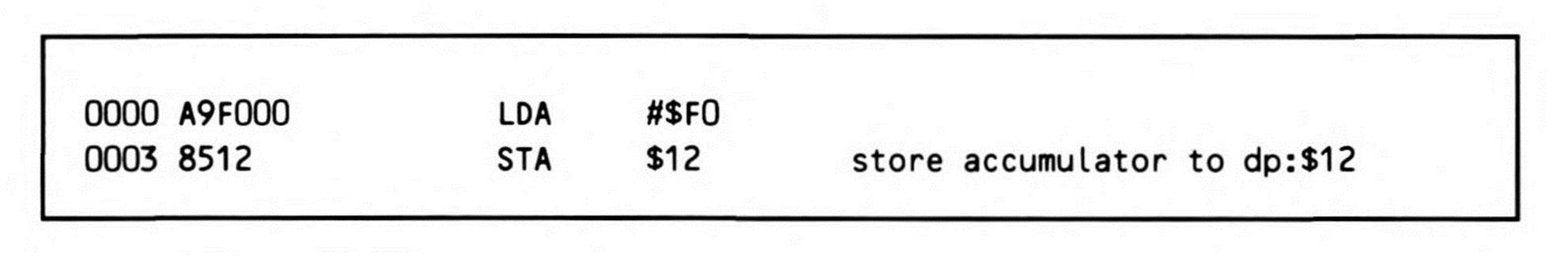
Fragment 11.3.
While it is common to speak of a direct page address of $12, $12 is really an offset from the base value in the direct page register ($FE00 in the last example). The two values are added to form the effective direct page address of $FE12.
But while Chapter 7 defined a page of memory as $100 locations starting from a page boundary (any multiple of $100), the direct page does not have to start on a page boundary; the direct page register can hold any sixteen-bit value. If the code in Fragment 11.4 is executed, running the code in Fragment 11.3 stores the one-byte value $F0 at address $1025; $1013 plus $12.
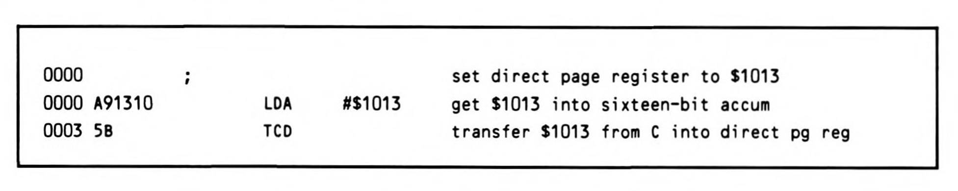
Fragment 11.4.
You will for the most part, however, want to set the direct page to begin on a page boundary: it saves one cycle for every direct page addressing operation. This is because the processor design includes logic that, when the direct page register's low byte is zero, concatenates the direct page register's high byte to the direct page offset—instead of adding the offset to the entire direct page register—to form the effective direct page address; concatenation saves a cycle over addition.
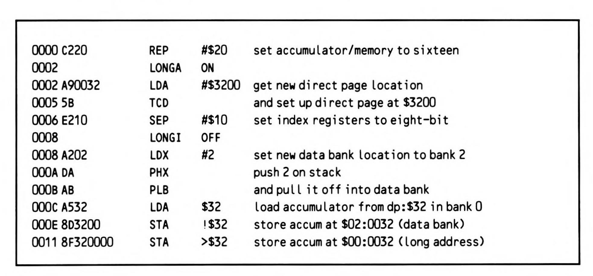
One of the benefits of the direct page concept is that programs, and even parts of programs, can have their own $100-byte direct pages of variable space separate from the operating system's direct page of variable space. A routine might set up its own direct page with the code in Fragment 11.5.
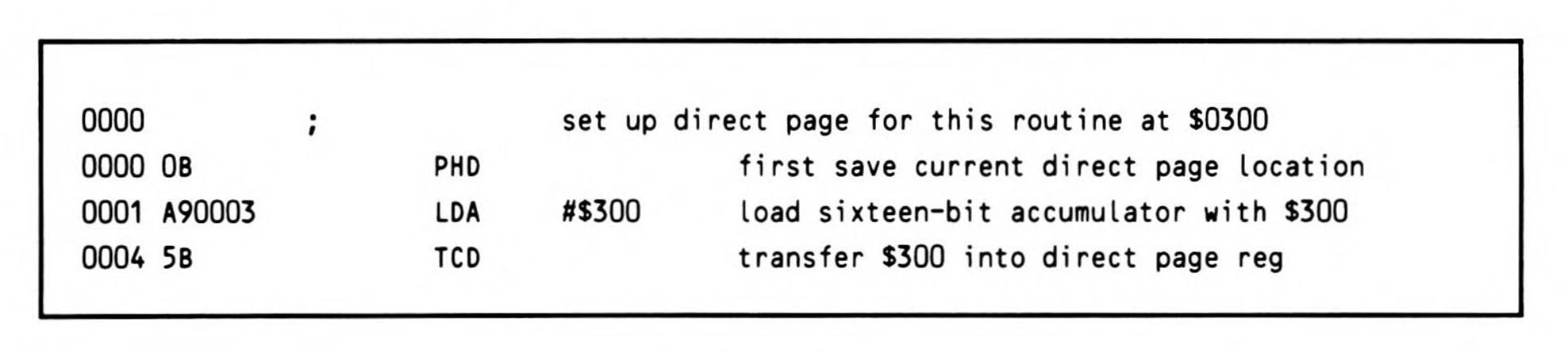
Fragment 11.5.
To end the routine and restore the direct page register to its previous value, simply execute a PLD instruction.
As discussed in Chapter 7, having a direct page makes accessing zero page addresses in any bank require special assembler syntax. Since the zero page is no longer special, absolute addressing must be used; but since the assembler normally selects direct page addressing for operands less than $100, the standard syntax requires that you prefix a vertical bar or exclamation point to the operand to force the assembler to use absolute addressing. This is just one of the potential assembler misassumptions covered in the next section.
Assembler Addressing Mode Assumptions
When the assembler encounters an address in the operand field of an instruction, it must decide whether the address is a direct page offset, a sixteen-bit absolute address, or a 24-bit long address and generate opcode and operand values which are appropriate. Its decision is based on the operand's size—not the number of digits in the operand, but whether the value of the operand is greater than $FF or greater than $FFFF. For example, the assembler will interpret the operand $3F to be a direct page offset regardless of whether it is written as $3F, $003F, or $00003F, because its value is less than 100 hex.
As a result, there are several areas of memory in 65802 and 65816 systems that the assembler will not access without entering the special syntax shown in Table 11.3 to override the assembler's assumptions.
Table 11.3. Assembler Syntax for Complete Memory Access.
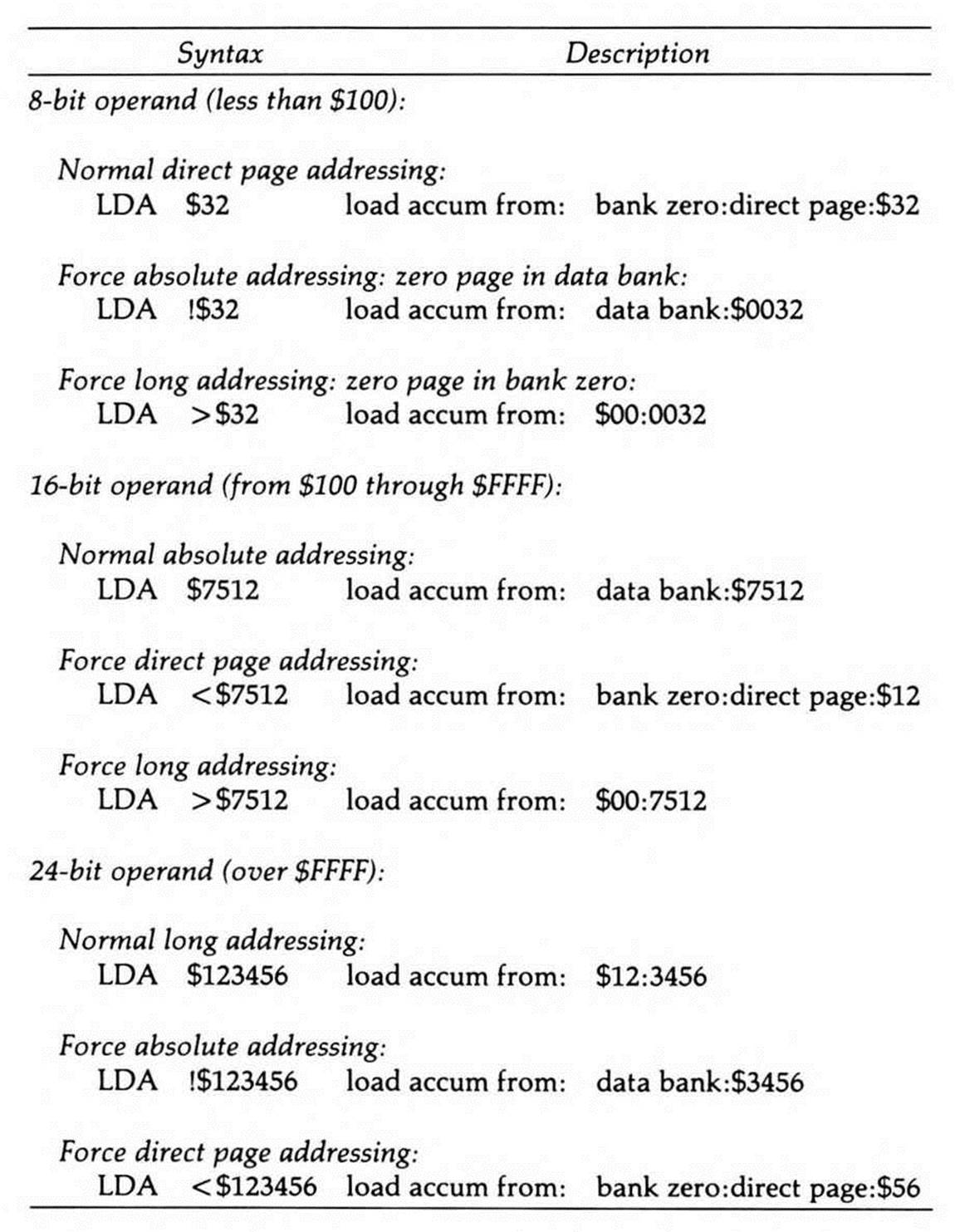
The first is zero page memory. Page zero has no special meaning in the 65802 and 65816: its special attributes have been usurped by the direct page, so accessing it requires use of absolute addressing just like any other absolute location. But the assembler assumes addresses less than $100 are direct page offsets, not zero page addresses; it will not generate code to access the zero page (unless the direct page is set to the zero page so that the two are one and the same) without explicit direction. And even if the direct page is set to the zero page, 65816 systems have a zero page not only in bank zero but also in every other bank, and those other page zeroes cannot ever be accessed by absolute addressing without special direction.
The syntax to force the assembler to use absolute addressing is to precede an operand with a vertical bar or exclamation point as shown in Fragment 11.6.
Fragment 11.6.
Notice the use of another symbol, the greater-than sign (>), to force long addressing. This solves another problem: The assembler assumes absolute addresses are in the data bank; if the value in the data bank is other than zero, then it similarly will not generate code to access bank zero without special direction. The greater-than sign forces the assembler to use a long addressing mode, concatenating zero high bits onto the operand until it's 24 bits in length. This usage is shown in Fragment 11.7, where the greater-than sign forces absolute long addressing, resulting in the assembler generating an opcode using absolute long addressing to store the accumulator, followed by the three absolute long address bytes for $00:0127, which are, in 65x order, $27, then $01, then $00.
The ASL instruction in Fragment 11.7 makes use of the third assembler override syntax: prefixing an operand with the less-than sign (<) forces direct page addressing. It's not likely you'll use this last syntax often, but it may come in handy when you've assigned a label to a value that you need the assembler to truncate to its low-order eight bits so it will be used as a direct page offset.
Note that this override syntax is the recommended standard syntax. As Chapter 1 (Basic Concepts) pointed out, even mnemonics can vary from one assembler to another, so assembler syntax such as this can differ as well.
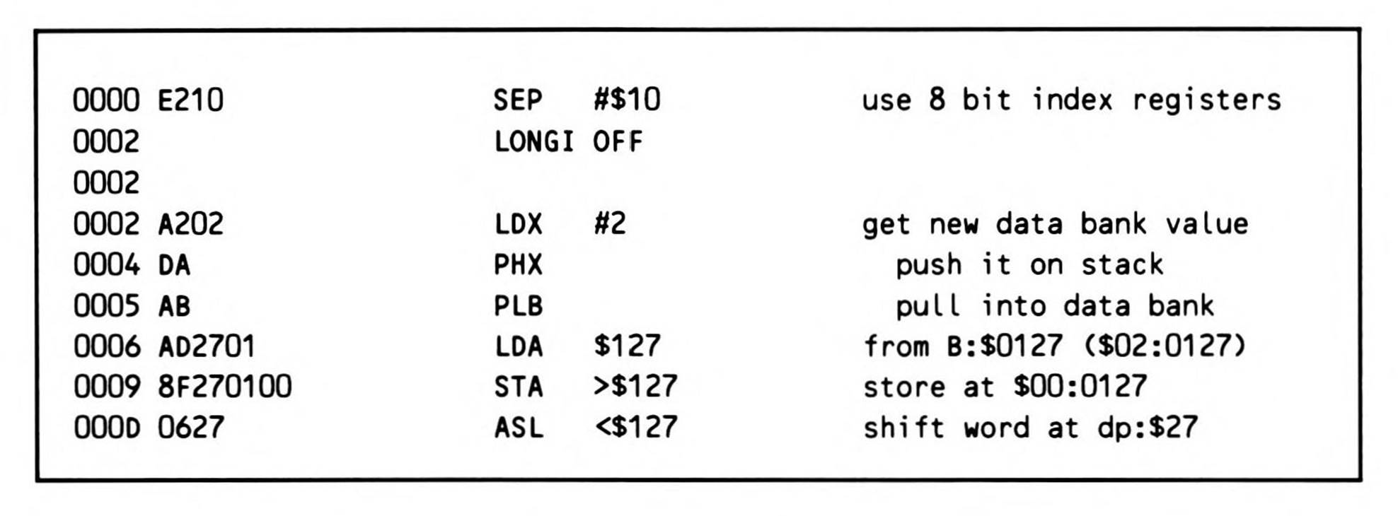
Fragment 11.7.
Direct Page Indirect Indexed with y Addressing
Direct page indirect indexed addressing or postindexing, which uses the Y register, is one of two ways indirect addressing can be combined with indexing (the other will be described in the next section). In postindexing, the processor goes to the location the direct page operand specifies and adds the index to the indirect address found there.
Like direct page indirect addressing, which was discussed in Chapter 7 (The Simple Addressing Modes), postindexing gives you the freedom to access a memory location which is not determined until the program is executing. As you also learned from Chapter 7, direct page indirect lets your program store the absolute address of a data bank location you want to access (this address is called the indirect address) into any two consecutive bytes in the direct page. This makes those two bytes perform as though they are an extra sixteen-bit register in the microprocessor itself. Further, it leaves the processor's registers unobstructed, and it allows data at the location stored in the direct page "register" to be accessed at any time.
Postindexing differs in that the absolute address you store into the direct page "register" is not one location but the base of an array; you can then access a particular byte in the array by loading its array index into the Y register and specifying, as your operand, the direct page "register" (the location of the indirect base of the array). As Figure 11.1 shows, the processor goes to the direct page offset, gets the absolute memory location stored there, then adds the contents of the Y register to get the absolute memory location it will access. The direct page offset, being in the direct page, is in bank zero on the 65816; the array, on the other hand, is in the data bank.
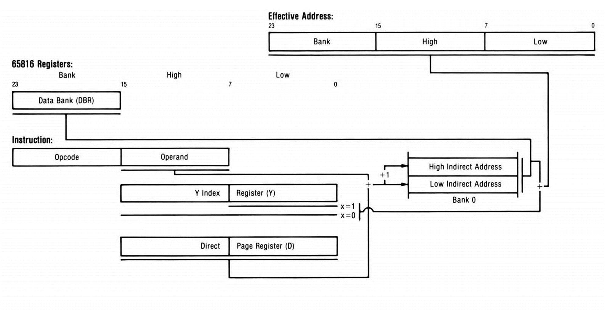
Figure 11.1. Postindexing.
This addressing mode is called postindexing because the Y index register is added after the indirect address is retrieved from the direct page.
For example, suppose that your program needs to write a dash (hyphen) character to a location on the Apple //'s 40-column screen that will be determined while the program is running. Further suppose your program picks a screen location at column nine on line seven. The Apple // has a firmware routine (called BASCALC) which, when presented with the number of a line on the screen, calculates the address of the leftmost position in the line and returns it in zero page location BASL, located at memory locations $0028 and $0029.
If you wanted to write your hyphen to the first position on the line, you could, after calling BASCALC and loading the character to print into the accumulator, use the 65C02's indirect addressing mode:

The 6502 has no simple indirect addressing mode, but Fragment 11.8 illustrates what 6502 programmers long ago learned: you can use postindexing to the same effect as simple indirect by loading the Y register with zero.
Fragment 11.8.
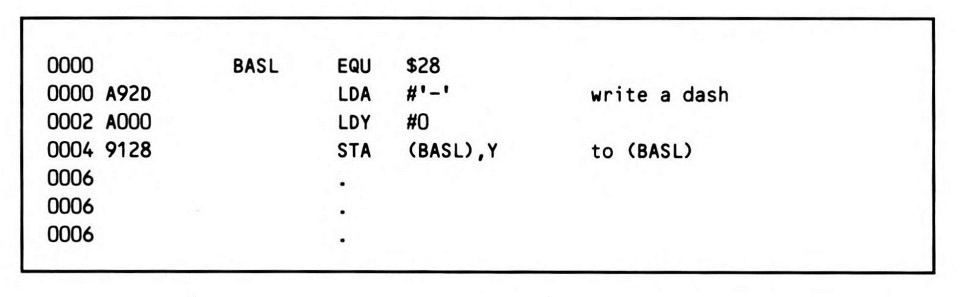
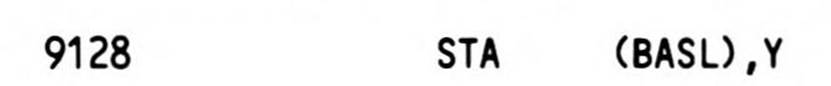
But you want to write the hyphen character to column nine (the leftmost position being column zero), not column zero. After calling BASCALC, you load the Y register with nine and write your character indirect through BASL indexed by the nine in Y as seen in Fragment 11.9. If BASCALC calculates line seven on the screen to start at location $780, and as a result stores that address at BASL, then the routine in Fragment 11.9 will write a dash to location $789 (column nine on line seven).
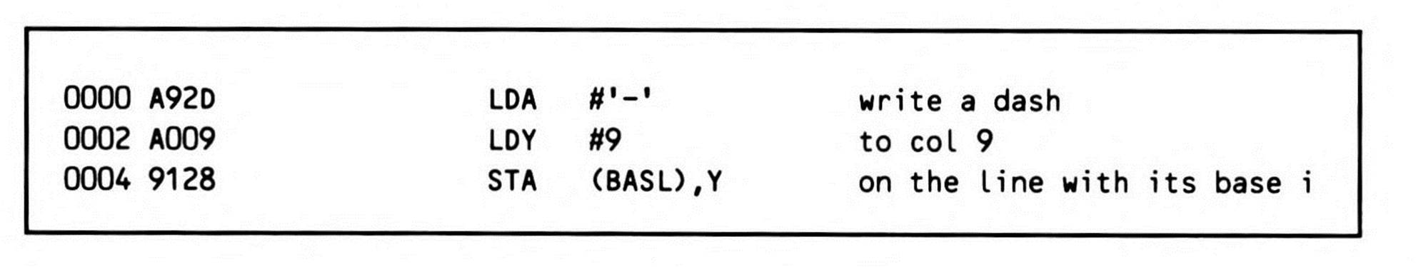
Fragment 11.9.
You could write a line of dashes from column nine through column sixteen simply by creating the loop coded in Listing 11.1. This kind of routine has been used for years on the 6502-based Apple //.
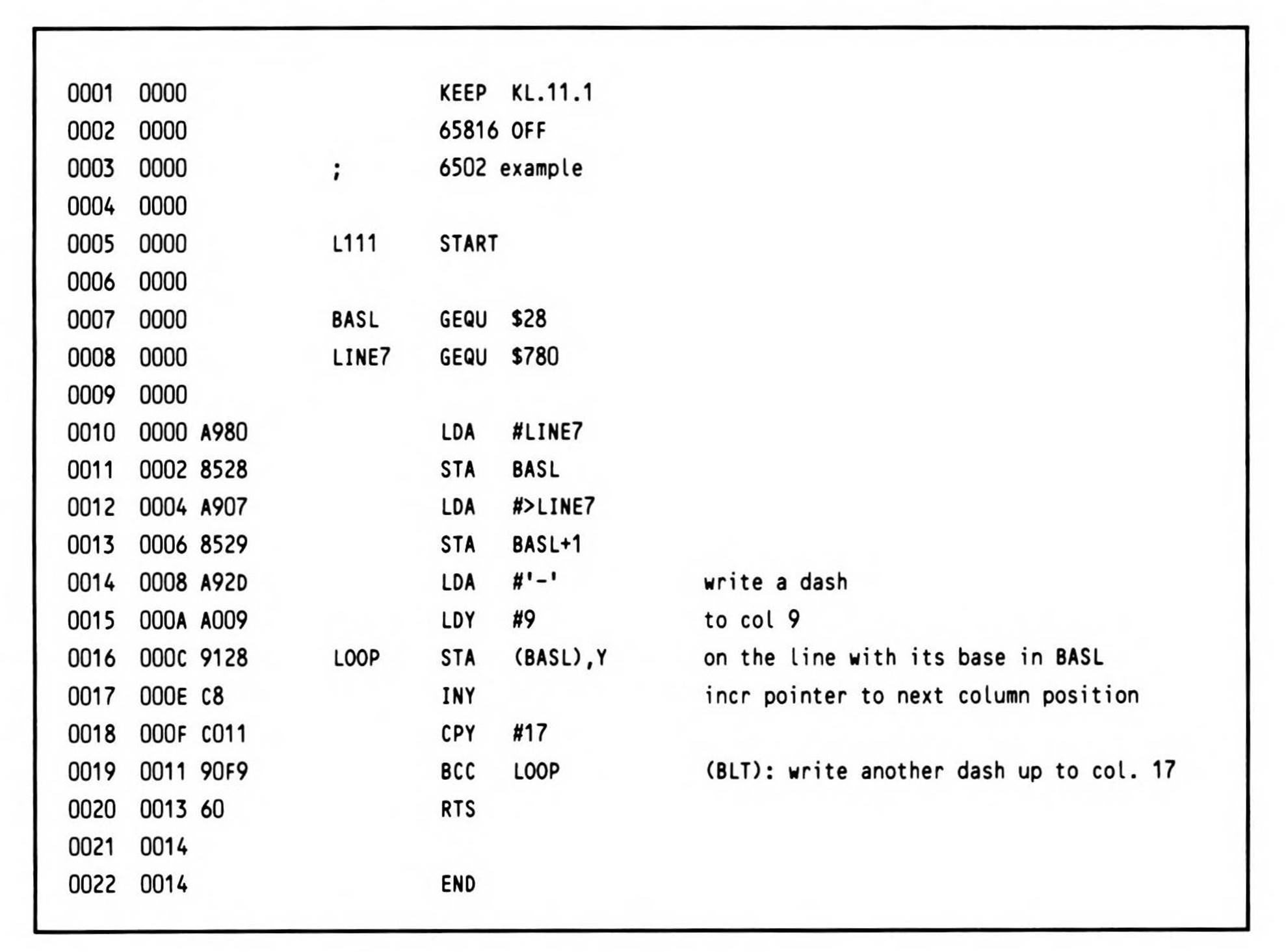
Listing 11.1.
Finally, note that, like absolute indexed addressing, the array of memory accessible to the indirect indexed addressing mode can extend beyond the current 64K data bank into the next 64K bank, if the index plus the array base exceeds $FFFF.
Direct Page Indexing Indirect Addressing
As the introduction to the last section pointed out, you can combine indexing with indirection in two ways. Postindexing, discussed in the last section, is one. The other is called direct page indexed indirect addressing or preindexing and uses the X register. It adds the index to the operand (a direct page base) to form a direct page offset at which the indirect address (the address of the data to be accessed) is located.
In effect, preindexing lets you index into a double-byte array of absolute memory addresses based in the direct page to choose the memory location to access; the array begins at the direct page offset specified by the operand.
Since the array base is a direct page location, adding the direct page register value yields the absolute location in bank zero. The processor then adds the value in the X register, which is the index into the array of memory locations. Now the processor finally has an address that holds the memory location you want to access; it now gets the location and accesses the data at that location. This is shown in Figure 11.2. Since indexing is done in order to find the indirect address, this addressing mode is also called preindexing.
You'll find preindexing useful for writing routines which need to access data in a number of different locations in exactly the same way. For example, a tic-tac-toe game drawn on the screen has nine boxes to which an 'O' or an 'X' might be written. The tic-tac-toe program might keep internal arrays of information about the content of each of the nine boxes, as well as arrays of data for working its win-seeking algorithms, using indexes from 0 to 8 to represent the locations.
When it comes time for the program to write an 'X' to a chosen square, you could, of course, write nine nearly identical routines which differ only in the address to which the 'X' will be written; you would also have to write a tenth routine to select which one of the routines needs to be called, based on the value of the box index (from zero to eight).
A faster and less wasteful method of writing the 'X' would be to use preindexing. In the section of code which initially draws the tic-tac-toe grid, you would determine the nine addresses where characters are to be written and store them into a direct page array, perhaps starting at direct page offset $50; this puts the 0 location at $50 and $51 (stored, in 65x fashion, low byte in $50 and high byte in $51), the 1 location at $52 and 53, and so on. The nine addresses use 18 bytes of memory.
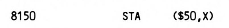
When an 'X' is to be stored to one of the nine screen locations, only one routine is necessary: you multiply the box number by two (using the ASL instruction). Remember that each indirect address takes up two bytes in the direct page array. Transfer it to the X register. Then load an 'X' character into the accumulator and write it to the box on the screen using preindexing as Fragment 11.10 shows.
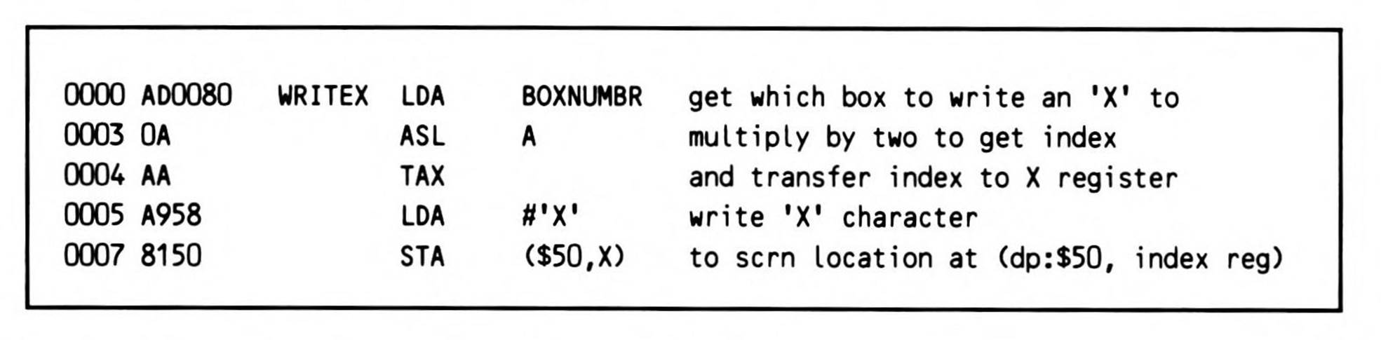
Fragment 11.10.
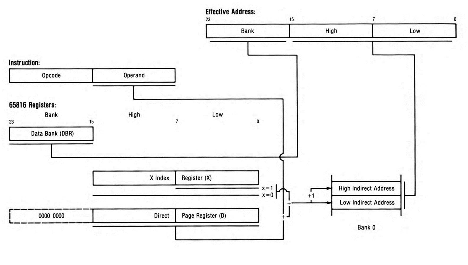
Figure 11.2. Preindexing.
Notice the differing syntax: postindexing looked like this:
In postindexed, the operand locates the indirect address, so it's in parentheses to indicate indirection. The ",Y" is not in parentheses, since the index register is not part of finding the indirect address—it's added to the indirect address once it is found.
On the other hand, with preindexing:
both the operand and the index register are involved in locating the indirect address, so both are in parentheses.
A very different application for preindexing enables the 65x to read from (or write to) several I/O peripherals "at once." Obviously, a microprocessor can only read from one device at a time, so it polls each device: provided each device uses the same I/O controller chip (so that a single routine can check the status of all devices and read a character from each of them identically), your program can poll the various status locations using preindexing. Begin by storing an array of all the status locations in the direct page. Specify the base of the array as the operand to a preindexed instruction. Load the X index with 0 and increment it by two until you've checked the last device. Finally, restore it to zero and cycle through again and again.
If a status check reveals a character waiting to be read, your program can branch to code that actually reads the character from the device. This time, you'll use preindexing to access a second direct page array of the character-reading addresses for each device; the index in the X register from the status-checking routine provides the index into the character-reading routine.
On the 6502, the 65C02, and the 6502 emulation modes, the entire array set up for preindexing must be in the direct page. (On the 6502 and 65C02, this means the array must be entirely in the zero page which, unfortunately, severely limits the use of preindexing due to the competition for zero page locations.) If the specified direct page offset plus the index in X exceeds $FF, the array wraps around within the direct page rather than extending beyond it. That is, would load the accumulator from the indirect address in location $0A, not $10A.
On the 65802 and 65816 (in native mode), the array must still start in the direct page but wraps, not at the end of the direct page, but at the end of bank zero, when the array base plus the D direct page setting plus the X index exceeds $00:FFFF.
On the 65816, the data that is ultimately accessed (after the indirection) is always in the data bank.
Absolute Indexed Indirect Addressing
The 65C02 introduced a new addressing mode, absolute indexed indirect addressing, which is quite similar to direct page indexed indirect. (It is also preindexed using the X index register, but indexes into absolute addressed memory rather than the direct page to find the indirect address.) This new addressing mode is used only by the jump instruction and, on the 65802 and 65816, the jump-to-subroutine instruction.
Absolute indexed indirect provides a method for your program, not to access data in scattered locations by putting the locations of the data into a table and indexing into it, but to jump to routines at various locations by putting those locations into a table, indexing into it, and jumping to the location stored in the table at the index. Figure 11.3 shows what happens.
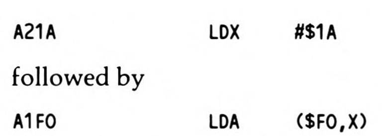
A menu-driven program, for example, could ask users to respond to a prompt by pressing a number key from '0' through '7'. Your program would convert the key's value to an index by subtracting the ASCII value of '0' and doubling the result (to reflect the fact that each table entry is an address and thus takes two bytes in the table) (Fragment 11.11). It would then jump indexed indirect to a routine appropriate to the menu choice.
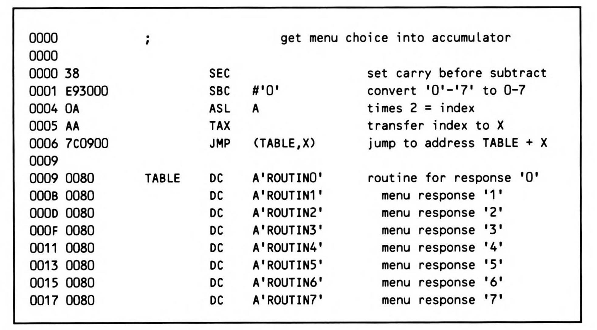
Fragment 11.11.
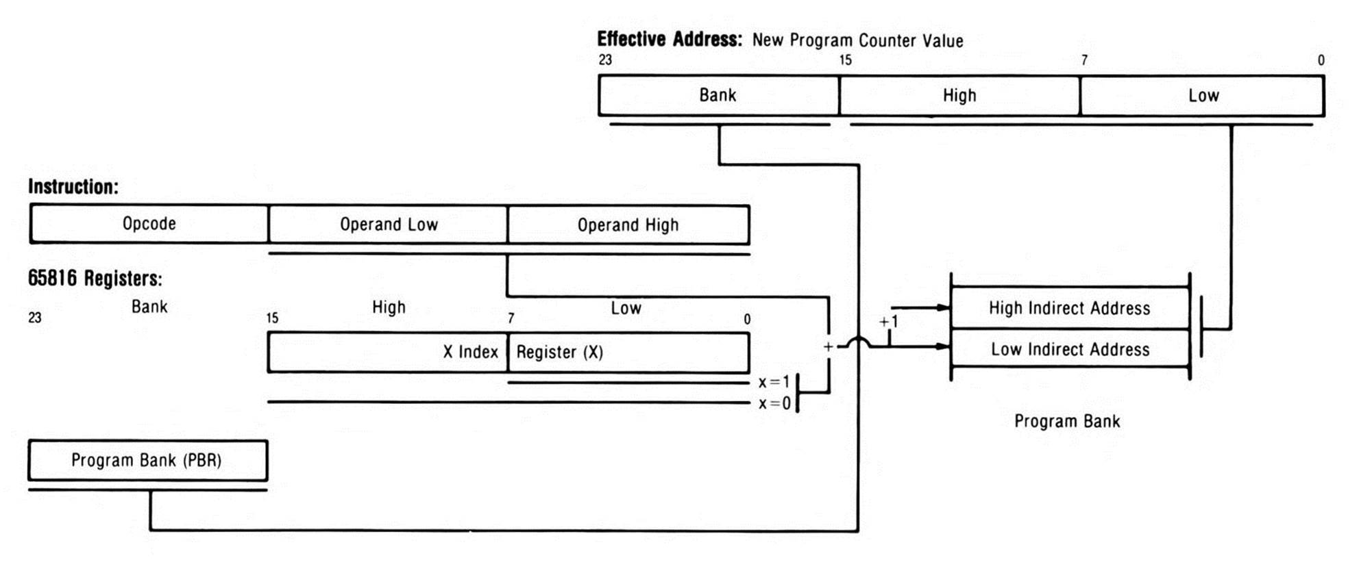
Figure 11.3. Absolute Indexed Indirect.
Because both the operand (the absolute address of the base of the table) and the index register are involved in determining the indirect address, both are within the parentheses.
On the 65816, a jump-indirect operand is in bank zero, but a jump-indexed-indirect operand is in the program bank. There is a different assumption for each mode. Jump indirect assumes that the indirect address to be jumped to was stored by the program in a variable memory cell; such variables are generally in bank zero. Jump indexed indirect, on the other hand, assumes that a table of locations of routines would be part of the program itself and would be loaded, right along with the routines, into the bank holding the program. So, assumes $1234 is in a double-byte cell in bank zero. But assumes $1234 is in the program bank, the bank in which the code currently being executed resides.


The indirect addresses stored in the table are absolute addresses also assumed to be in the current program bank.
Direct Page Indirect Long Indexed with Y Addressing
The 65816 can access sixteen megabytes of memory, yet lets you access most data (data located in the current data bank) with just two bytes. Nevertheless, there are times when data must be accessed in a bank other than the current data bank when it would be inconvenient to change the data bank, then change it back. As Chapter 7 pointed out, this problem is solved by the "long" addressing modes, which allow three bytes (the bank in addition to the address within the bank) to specify a full 24-bit address. This solution lets you access the 65816's full sixteen-megabyte address space. Probably the most useful way to reference data outside of the current data bank is via the direct page indirect long indexed with Y, or postindexed long, addressing mode. This is the long version of direct page indirect indexed addressing, discussed earlier in this chapter.
Instructions are two bytes in length, as shown in Figure 11.4: The opcode is followed by a single byte, which is a direct page offset in bank zero. The indirect address stored in the direct page (to which the operand points) is, in the long version, three bytes (a full 24-bit address); the byte at the direct page offset is the low byte of the 24-bit address, the byte in the next direct page location the middle byte of the 24-bit address, and the byte in the third location the bank byte of the 24-bit address. The contents of the Y index register are added to this 24-bit address to form the 24-bit effective address at which data will be accessed.
The syntax for postindexed long is:

The square brackets are used to indicate the indirect address is long.
So, like its sixteen-bit counterpart, indirect long indexed addressing allows you to index into an array of which neither the base nor the index need be determined until the program is executing. Unlike its sixteen-bit counterpart, it allows you to access an array in any bank, not just the current data bank.
Stack Relative Addressing
Possibly the most exciting new addressing method introduced by the 65802 and 65816 is stack relative. This is the first 65x method for directly accessing a stack byte other than the last data item pushed.
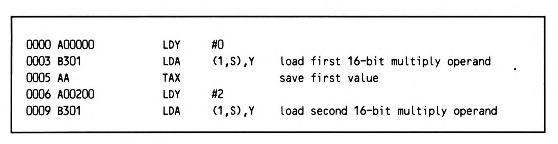
Stack relative addressing lets you easily access any byte or address in the last $FF bytes stacked. Instructions using stack relative addressing are two bytes long, the operand a single byte that is an index into the stack. As Figure 11.5 shows, the stack is treated as an array with its base the address in the stack pointer. The operand is added to the stack pointer value to form the bank zero effective address which will be accessed.
This can be especially useful when one part of a program needs to send data to another part of the program, such as a multiply routine. The two sixteen-bit values to be multiplied are pushed onto the stack in one part of the program. Later, the multiply routine loads one of the operands using stack relative addressing, leaving both the other operand and the stack pointer undisturbed:
Notice that accessing the last data put on the stack requires an index of 1, not of 0. This is because the stack pointer always points to the next available location, which is one byte below the last byte pushed onto the stack. An index of zero would generally be meaningless, except perhaps to re-read the last byte pulled off the stack! (The latter would also be extremely dangerous since, should an interrupt occur, the left-behind byte would be overwritten by interrupt-stacked bytes.)
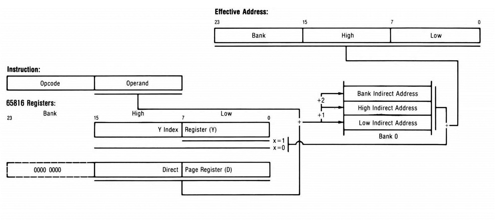
Figure 11.4. Postindexed Long.
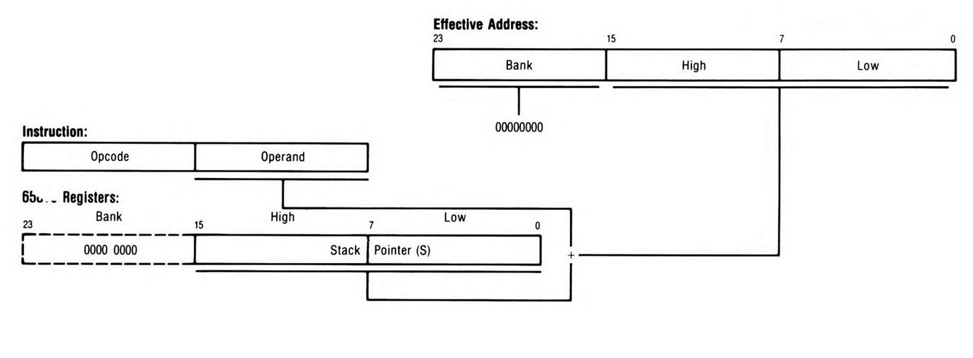
Figure 11.5. Stack Relative.
Stack Relative Indirect Indexed Addressing
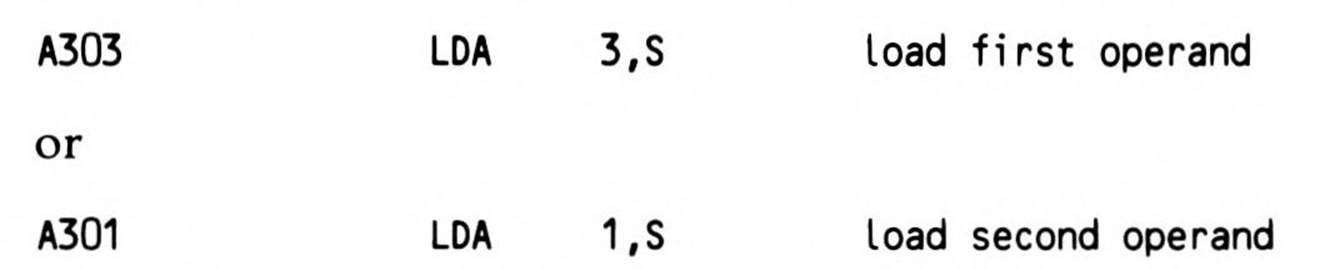
While the stack relative addressing mode serves to access data on the stack, the stack relative indirect indexed addressing mode lets you access data indirectly through addresses that have been pushed onto the stack.
Change the previous example: Instead of stacking the two sixteen-bit values to be multiplied, the values are found in memory cells in the data bank, one after the other (occupying four consecutive bytes), and it's the address of the first that is pushed onto the stack. Now, asFragment 11.12 shows, either value can be loaded using the stacked indirect address:
Fragment 11.12.
The 1,S is the stack location where the indirect address was pushed. (Actually, 1,S points to the stack location of the low byte of the indirect address; the high byte is in 2,S, the next higher stack location.) To this indirect address, the value in Y is added: the indirect address plus 0 locates the first value to be multiplied; the indirect address plus 2 locates the second. Finally the accumulator is loaded from this indirect indexed address. Figure 11.6 illustrates the sequence.
This mode, very similar to direct page indirect indexing (also called postindexing), might be called "stack postindexing." The operand which indexes into the stack is very similar to a direct page address; both are limited to eight bits and both are added to a sixteen-bit base register (D or S). In both cases, the indirect address points to a cell or an array in the data bank. In both cases, Y must be the index register. And in both cases in the 65816, the postindexed indirect address about to be accessed may extend out of the data bank and into the next bank if index plus address exceeds $FFFF; that is, if the indirect address is the base of an array, the array can extend into the next bank.
Push Effective Instructions
The 65802 and the 65816 provide three instructions which push, not registers, but absolute, indirect, and relative addresses straight onto the stack. These three instructions are PEA, PEI, and PER, the apush effective address instructions. Addresses so pushed might be accessed, for example, using the stack relative indirect indexed addressing mode just discussed. Chapter 6, which introduced the push instructions in the context of data movement, deferred discussion of these three instructions to this chapter. Except for the block move instructions, these are the only instructions that move data directly from one memory location to another.
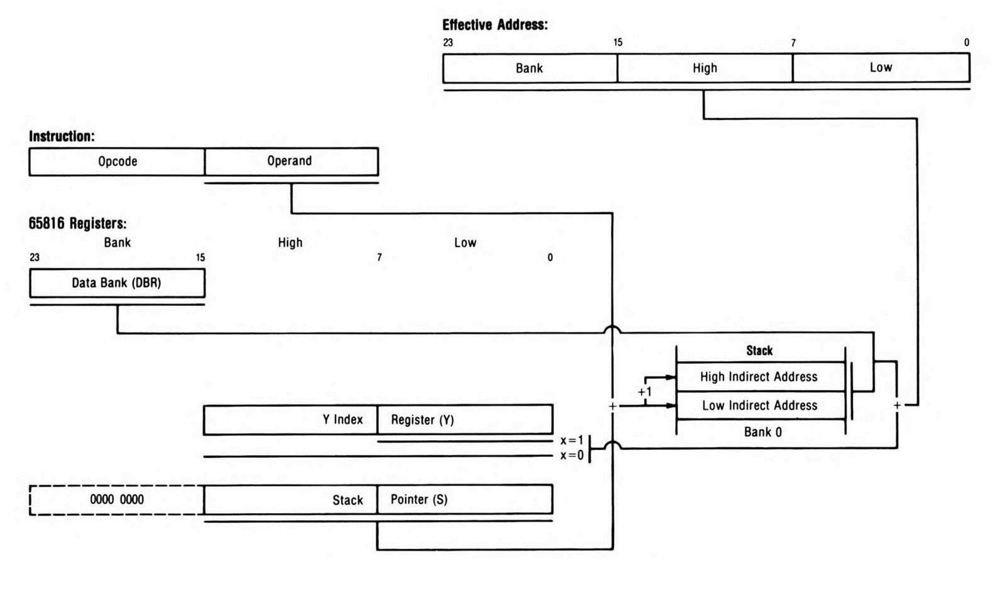
Figure 11.6. Stack Relative Indirect Indexed.
As Figure 11.7 shows, the PEA (push effective absolute address) instruction pushes the operand, a 16-bit absolute address or immediate data word, onto the stack. For example, pushes what may be either sixteen-bit immediate data or a sixteen-bit address onto the stack. The operand pushed by the PEA instruction is always 16 bits regardless of the settings of the m memory/accumulator and x index mode select flags.

The PEI (push effective indirect address) instruction has, as an operand, a direct page location: it's the sixteen-bit value stored at the location that is pushed onto the stack. Figure 11.8 shows that this has the effect of pushing either an indirect address or sixteen bits of direct page data onto the stack. For example, if you had stored the value or indirect address $5678 at direct page location $21, then would get the $5678 from the direct page location and push it onto the stack. Like the PEA instruction, the PEI instruction always pushes sixteen bits regardless of the settings of the m memory/accumulator and x index mode select flags.

The PER (push effective relative) instruction pushes an effective program counter relative address onto the stack, a capability helpful in writing relocatable code. The operand you specify to the assembler is a location in the program, for example, of a data area; the operand the assembler generates is a sixteen-bit relative displacement, the difference between the next instruction's address and the operand address. Figure 11.9 shows that when the instruction is executed, the displacement is added to the next instruction's run-time address to form the address at which the data is now located; it is this address which is pushed onto the stack. If the data location precedes the PER instruction, the assembler generates a very large sixteen-bit displacement which, when added to the program counter value, will wrap around within the program bank to reach the data.
The operation of the PER instruction is similar to the operation of the BRL (branch long) instruction: the branch long operand you specify to the assembler is also a location in the program; the operand the assembler generates is also a sixteen-bit displacement; and when the instruction is executed, the displacement is added to the next instruction's run-time address to form the address to which the program will branch.
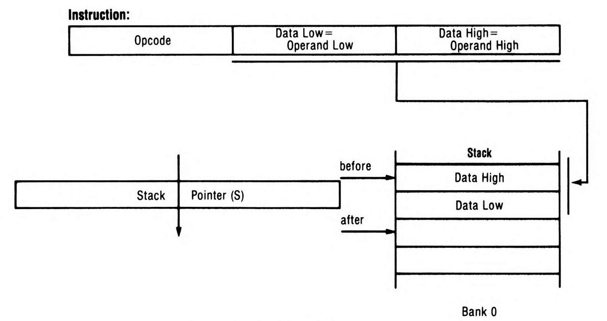
Figure 11.7. PEA Addressing.
Figure 11.8. PEI Addressing.
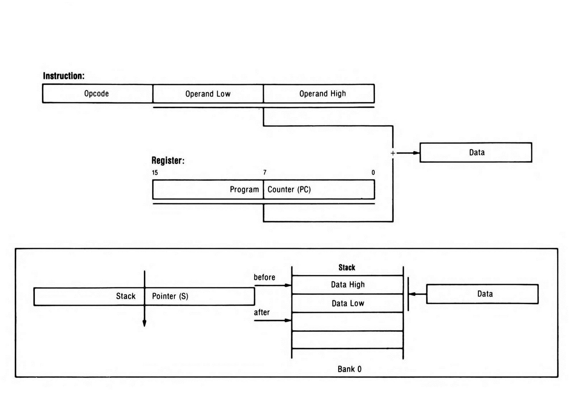
Figure 11.9. PER Addressing.
To understand the use of the PER instruction, together with the relative branches, in writing a program that will run at any address, suppose that your relocatable program is assembled starting at location $2000. There's a data area starting at location $2500 called DATA0. A section of program code at $2200 needs to access a byte three bytes past, called DATA1. A simple LDA $2503 would work, but only if the program were intended to always begin at location $2000. If it's meant to be relocatable, you might load the program at $3000, in which case the data is at $3503 and a LDA $2503 loads the accumulator with random information from what is now a non-program address. Using the instruction

in your source program causes the assembler to calculate the offset from $2203 (from the instruction following the PER instruction at $2200) to DATA1 at $2503, an offset of $300. So the assembler generates object code of a PER opcode followed by $300. Now if the code is loaded at $3000, execution of the PER instruction causes the processor to calculate and stack the current absolute address of DATA1 by adding the operand, $300, to the current program counter location; the result is $3503, so it's $3503 that's stacked. Once on the stack, provided the program and data banks are the same, the data can be accessed using stack relative indirect indexed addressing. Fragment 11.13 contains the example code.
Once the address of DATA1 is on the stack, the values at DATA2 and DATA3 can be accessed as well simply by using values of one and two, respectively, in the Y index register.
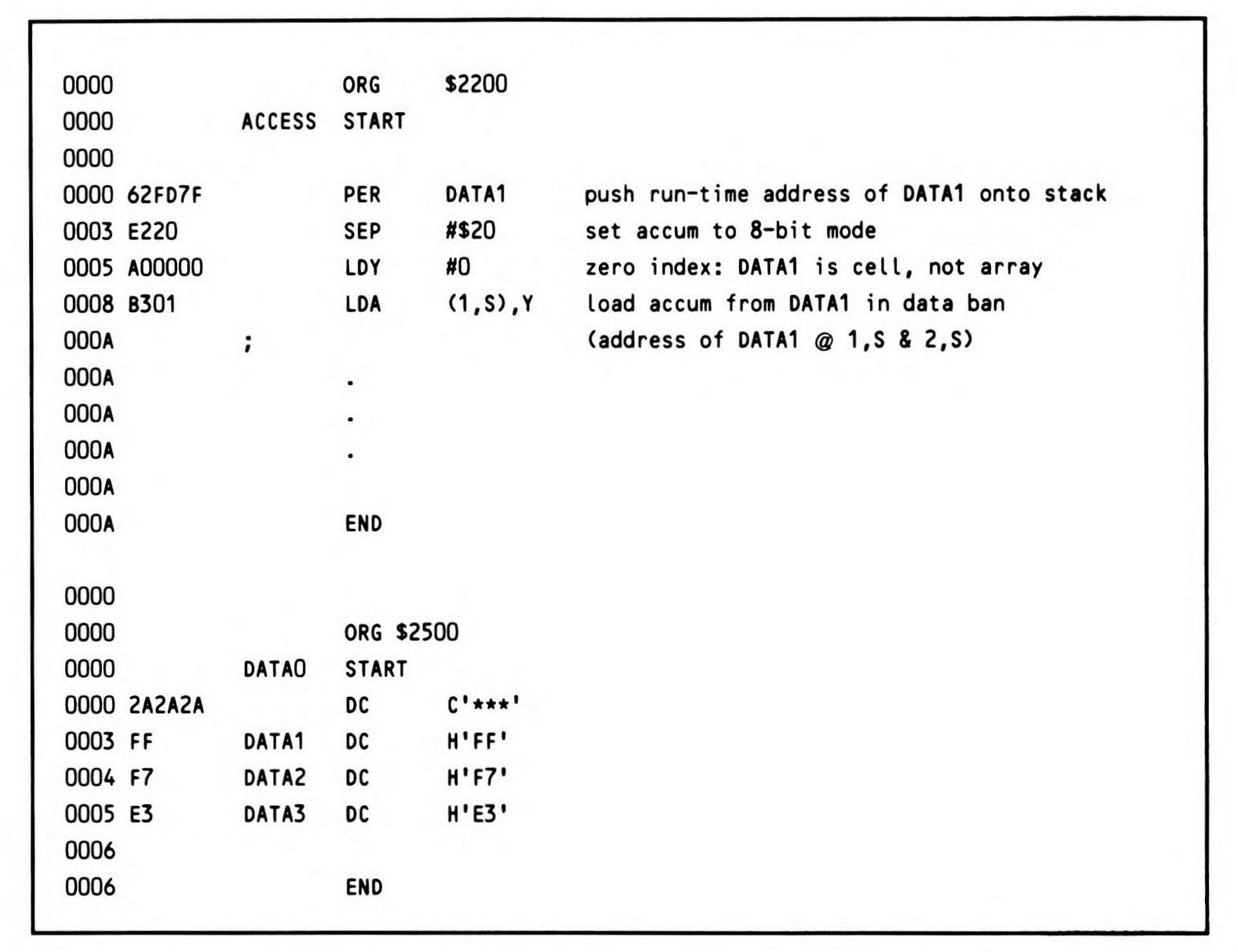
Fragment 11.13.
All materials on the site are licensed Creative Commons Attribution-Sharealike 3.0 Unported CC BY-SA 3.0 & GNU Free Documentation License (GFDL)
If you are the copyright holder of any material contained on our site and intend to remove it, please contact our site administrator for approval.
© 2016-2026 All site design rights belong to S.Y.A.