Programming the 65816 Including the 6502, 65C02, and 65802 (1986)
Part IV. Applications
14. Selected Code Samples
This chapter contains five different types of example programs, which are examined in detail. Each focuses on a different topic of interest to the 65x programmer: multiplication and division algorithms; a 65802-to-6502 mode-switching tour de force; a quick utility routine to determine which 65x processor a program is running under; high-level languages; and a popular performance benchmark.
Multiplication
Probably the most common multiply routine written for eight-bit applications is to multiply one sixteen-bit number by another, returning a sixteen-bit result. While multiplying two large sixteen-bit numbers would yield a 32-bit result, much of systems programming is done with positive integers limited to sixteen bits, which is why this multiply example is so common. Be aware that a result over sixteen bits cannot be generated by the examples as coded—you'll have to extend them if you need to handle larger numbers.
There are several methods for the sixteen-by-sixteen multiply, but all are based on the multiplication principles for multi-digit numbers you were taught in grade school: multiply the top number by the right-most digit of the bottom number; move left, digit by digit, through the bottom number, multiplying it by the top number, each time shifting the resulting product left one more space and adding it to the sum of the previous products:
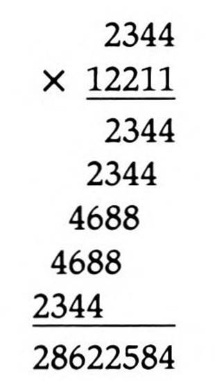
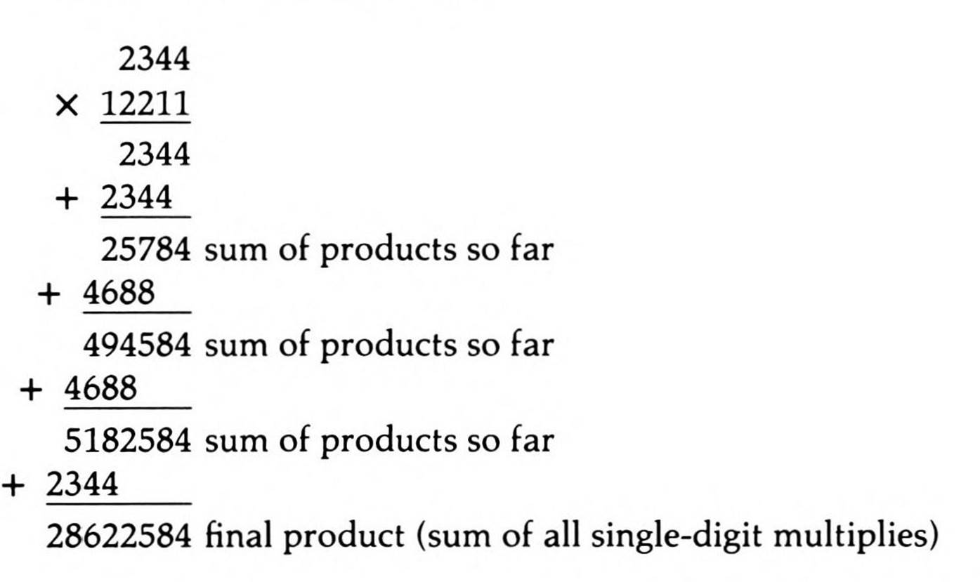
Or to better match the description:
Binary multiplication is no different, except that, since each single-digit multiply is by either zero or one, each resulting single-digit product is either the top number itself or all zeroes.
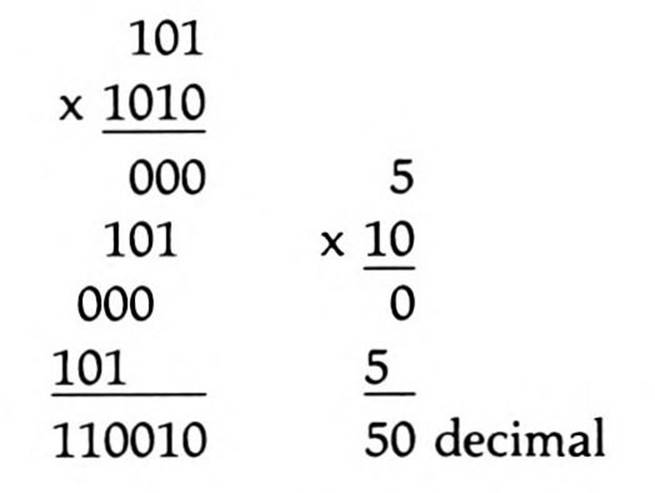
To have the computer do it, you have it shift the bottom operand right; if it shifts out a zero, you need do nothing, but if it shifts out a one, you add the top number to the partial product (which is initialized at zero). Then you shift the top number left for the possible add during the next time through this loop. When there are no more ones in the bottom number, you are done.
6502 Multiplication
With only three eight-bit registers, you can't pass two sixteen-bit operands to your multiply routine in registers. One solution, the one used below, is to pass one operand in two direct page (zero page) bytes, while passing the other in two more; the result is returned in two of the 6502's registers. All this is carefully documented in the header of the routine in Listing 14.1.
This 6502 multiply routine takes 33 bytes.
65C02 Multiplication
With the same three eight-bit registers as the 6502, and an instruction set only somewhat enhanced, the 65C02 multiply routine is virtually the same as the 6502s. Only one byte can be saved by the substitution of an unconditional branch instruction for the jump instruction, for a total byte count of 32.
65802 and 65816 Multiplication
The 65802 and 65816, when running in native mode, have three registers, all of which can be set to sixteen bits, in addition to having many more addressing modes. As you might expect, a multiply routine for these processors is considerably shorter than the 6502 and 65C02. What you might not expect is how much shorter: the multiply routine in Listing 14.2 for the 65802 and 65816 takes only 19 bytes—its length is less than 60 percent of each of the other two routines!
Notice the additional documentation at the beginning of the routine. The processor must have both its index registers and its accumulator in sixteen-bit modes before calling this routine.
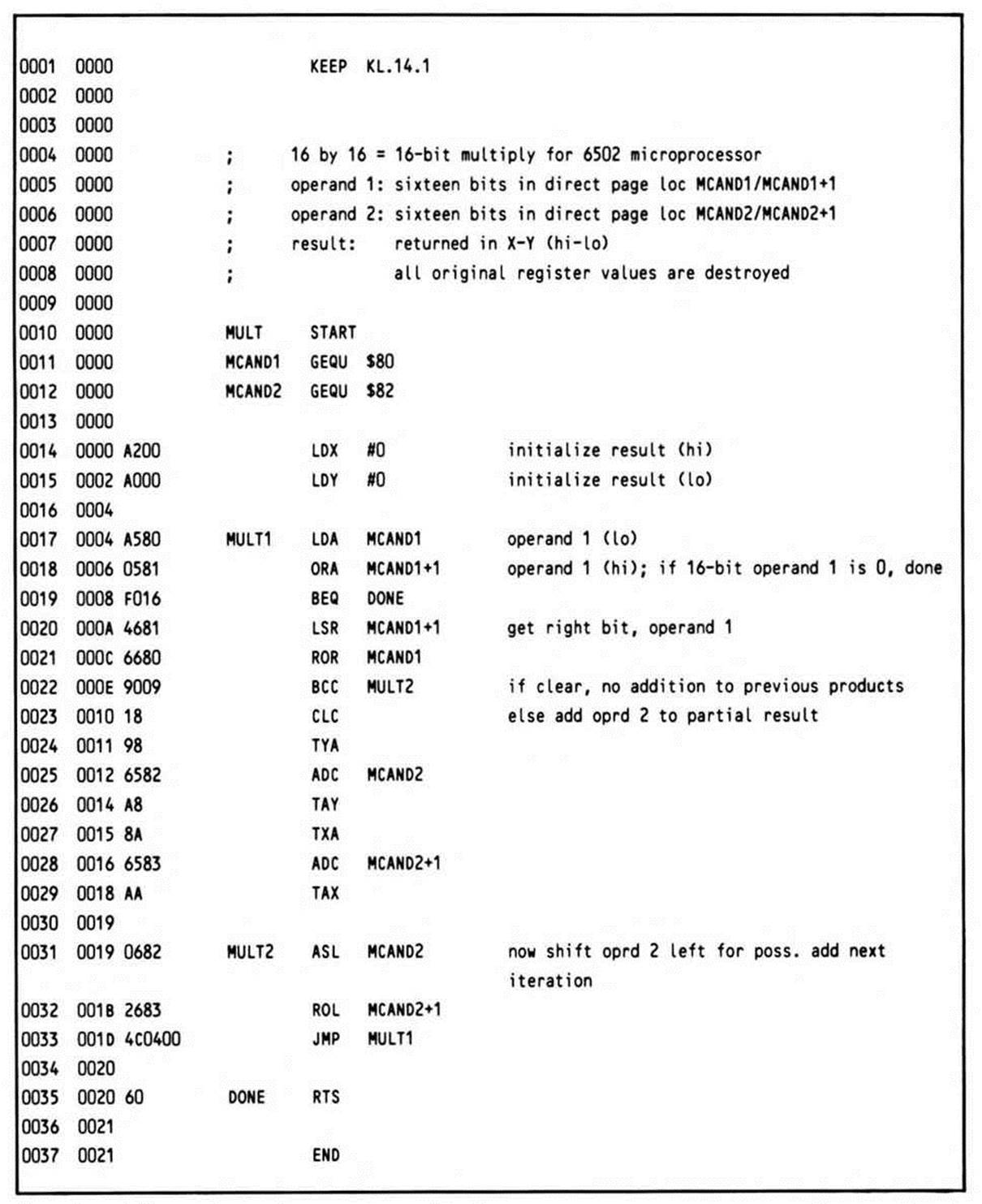
Listing 14.1.
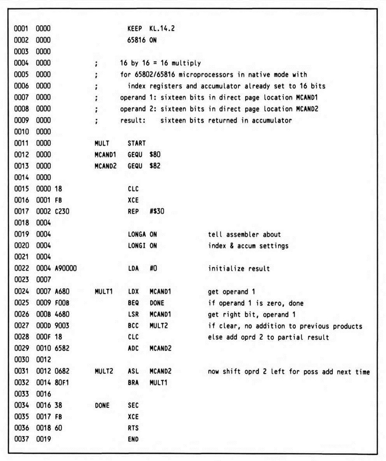
Listing 14.2.
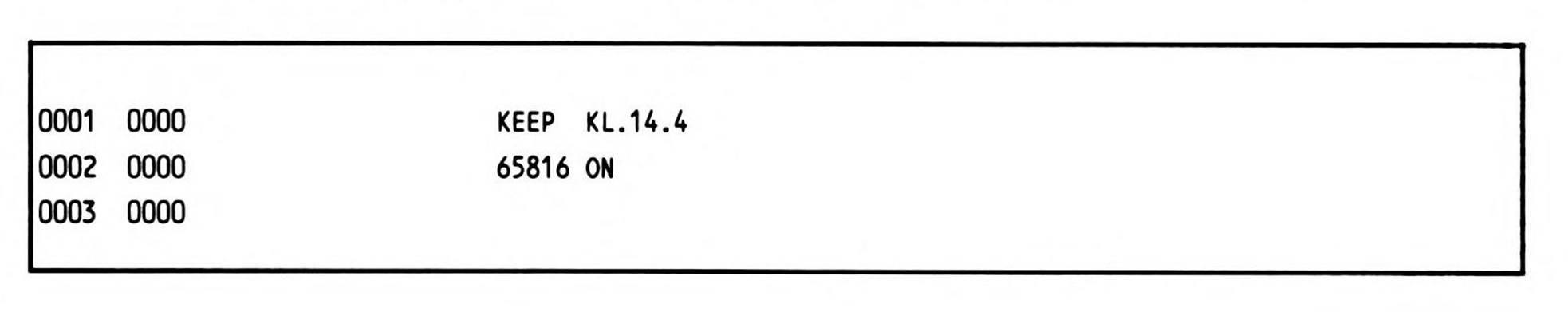
Along the same lines, notice that the first two lines of the subroutine are the mode directives—LONGA ON and LONGI ON—which inform the assembler that all three registers have been set to sixteen bits. That way, when the accumulator is loaded with immediate zero, the assembler will generate a sixteen-bit operand rather than an incorrect eight-bit one, which would cause program failure when executed.
The RTS instruction is the intra-bank return instruction. An RTL instruction could be substituted if the subroutine were intended to be called only by long jump-to-subroutine instructions, whether by code outside the bank or by code within it. You should document such a requirement in the routine's introductory comments.
Division
Probably the most common division routine written for eight-bit applications is the converse of the multiply routine just covered—to divide one sixteen-bit number by another sixteen-bit number, returning both a sixteen-bit quotient and a sixteen-bit remainder.
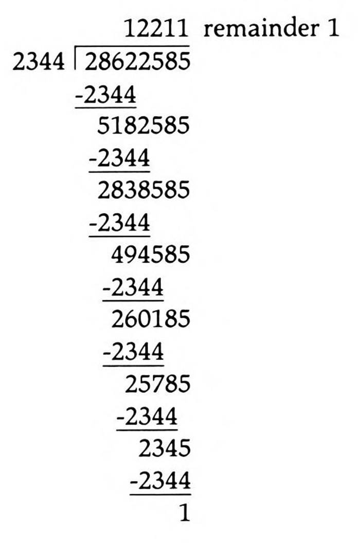
There are several methods for doing this, but all are based on the division principles for multi-digit numbers that you learned in grade school. Line up the divisor under the left-most set of digits of the dividend, appending an imaginary set of zeroes out to the right, and subtract as many times as possible. Record the number of successful subtractions; then shift the divisor right one place and continue until the divisor is flush right with the dividend, and no more subtractions are possible. Any unsubtractable value remaining is called the remainder.
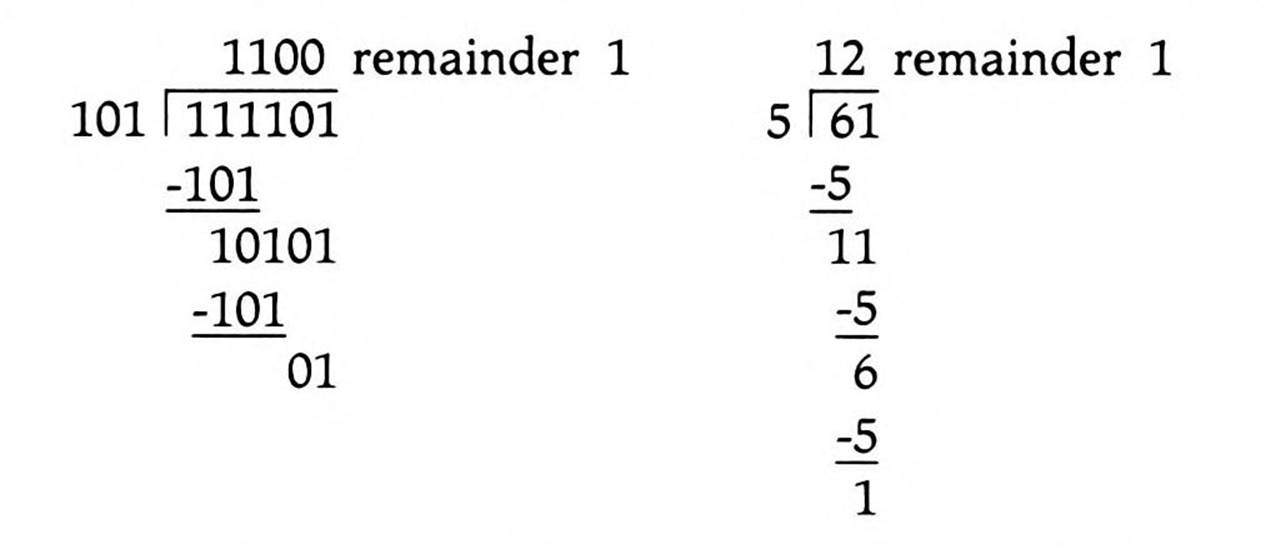
Binary division is even easier since, with only ones and zeroes, subtraction is possible at each digit position either only once or not at all:
Many programs calling this division routine will need only the quotient or only the remainder, although some will require both. The routines here return both.
6502 Division
The 6502, with its three eight-bit registers, handles passing parameters to and from a division routine even less smoothly than to and from a multiplication routine: not only do you need to pass it two sixteen-bit values, but it needs to pass back two sixteen-bit results.
The solution used in Listing 14.3 is to pass the dividend and the divisor in two direct page double bytes, then pass back the remainder in a direct page double byte and the quotient in two registers.
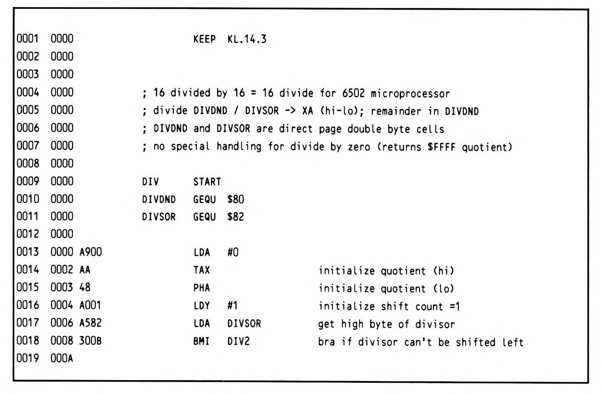
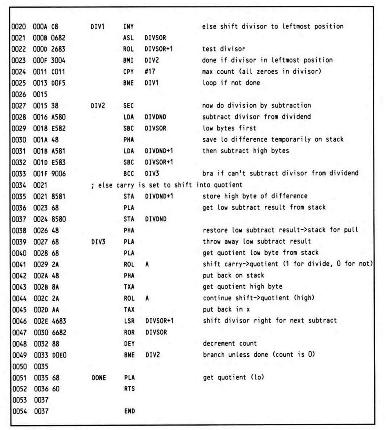
Listing 14.3.
The label DONE is not needed (there is no branch to the location), but was added for clarity.
The routine at DIV2 may seem curious. The 6502 has no sixteen-bit compare; to compare two sixteen-bit numbers, you must actually subtract them (setting the carry first, as is required before a subtract using the 65x SBC instruction). So the divisor is subtracted from the dividend, with the low result saved on the stack. If the carry is clear, the divisor is too large to be subtracted from the dividend. Thus a branch is taken to DIV3, where the low result is pulled but not used and the cleared carry is rolled into the quotient to acknowledge the unsuccessful subtraction. If the carry is set, then the high result, still in the accumulator, is stored, and the low result is pulled from the stack, stored, then restacked to be repulled at DIV3; since the carry is known to be set, it does not need to be explicitly set before rolling it into the quotient to acknowledge the successful subtraction.
The quotient is returned in registers X and A.
This 6502 divide routine takes 55 bytes.
65C02 Division
The 65C02 routine is virtually the same; only three early instructions (shown in Fragment 14.1) in the 6502 routine are changed to the code in Fragment 14.2, for a net savings of one byte, because the 65C02 has instructions to push the index registers. This 65C02 divide routine takes 54 bytes, one byte fewer than the 6502 divide routine takes.
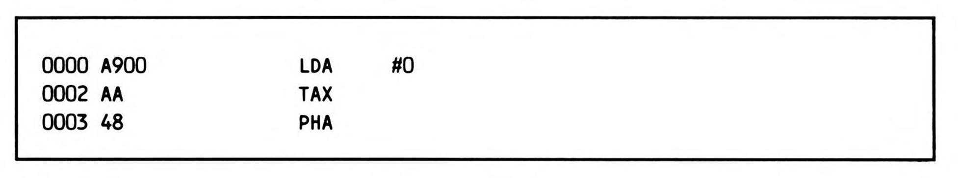
Fragment 14.1.
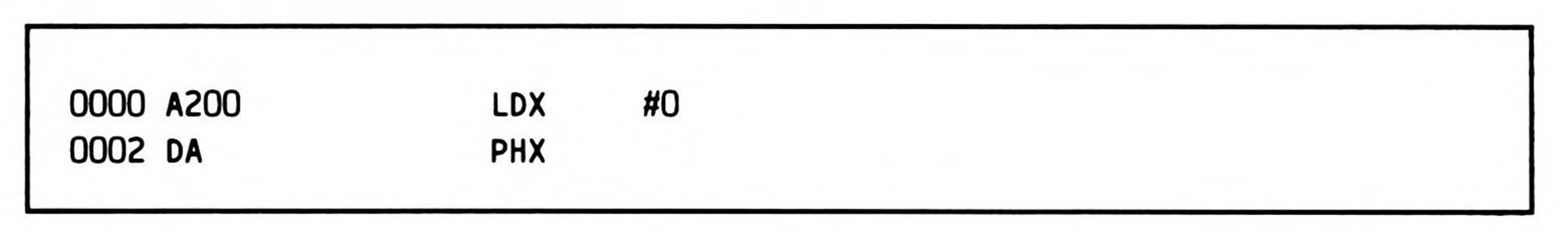
Fragment 14.2.
65802/65816 Division
The 65802 and 65816 processors, with their registers extendable to sixteen bits, can handle sixteen-bit division with ease. In the divide routine in Listing 14.4, the dividend and the divisor are passed in sixteen-bit registers X and A respectively; the quotient is passed back in a sixteen-bit direct page location and the remainder in X.
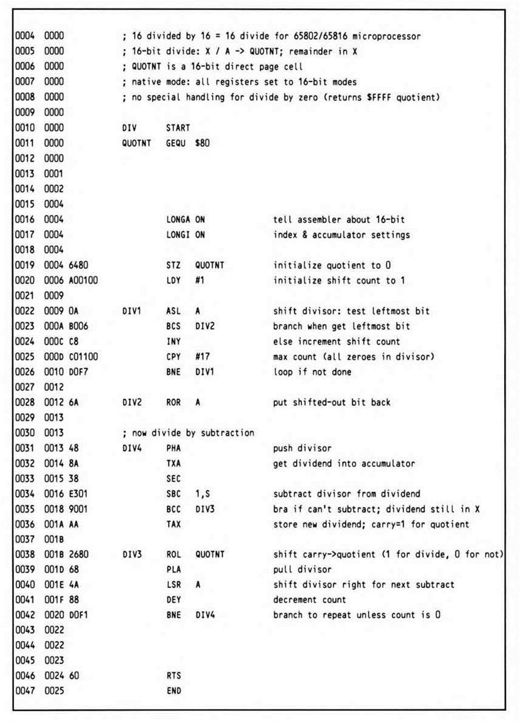
Listing 14.4.
This divide routine for the 65802 and 65816 generates only 31 bytes, little more than half the bytes the 6502 and 65C02 divide routines generate.
As the introductory comments note, it requires the processor to be in native mode and the m and x memory select flags to be in sixteen-bit modes before the routine is called; these requirements become doubly obvious when you see in another of the comments that the values passed in the accumulator and an index register are sixteen bits, with one of the two sixteen-bit results being passed back in one of the same registers. Assemblers, however, do not read comments; they only read instructions and directives. That's the reason for the LONGA ON and LONGI ON directives at the beginning of the routine.
Calling an Arbitrary 6502 Routine
Particularly during the early phases of the processor's life cycle, you might wish to mix existing 6502 code with your 65816 applications. The routine provided below provides a general purpose way of doing this. Additionally, the context-saving code illustrated here could prove useful in other applications. You'll find similar code in the debugger in the next chapter, where it is needed to save the context between instructions of the user program being traced.
The simplest way to call a 6502 routine from the 65802 or 65816 is found in Fragment 14.3.
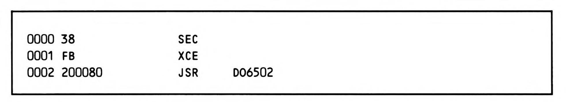
Fragment 14.3.
Although this will work fine in some cases, it is not guaranteed to. In order to be assured of correct functioning of an existing 6502 routine, the direct page register must be reset to zero and the stack pointer must be relocated to page one. Although a 6502 program that uses zero page addressing will technically function correctly if the direct page has been relocated, the possibility that the zero page may be addressed using some form of absolute addressing, not to mention the probability that an existing 6502 monitor or operating system routine would expect to use values previously initialized and stored in the zero page, requires that this register be given its default 6502 value.
If the stack has been relocated from page one, it will be lost when the switch to emulation mode substitutes the mandatory stack high byte of one. So first, the sixteen-bit stack pointer must be saved. Second, if the 65802/65816 program was called from a 6502 environment, then there may be 6502 values on the original 6502 page-one stack; such a program must squirrel away the 6502 stack pointer on entry so it can be restored on exit, as well as used during temporary incursions, such as this routine, into the 6502 environment.
The goal, then, is this: provide a mechanism whereby a programmer may simply pass the address of a resident 6502 routine and any registers required for the call to a utility which will transfer control to the 6502 routine; the registers should be returned with their original (potentially sixteen-bit) values intact, except as modified by the 6502 routine; and finally the operating mode must be restored to its state before the call.
When loading the registers with any needed parameters, keep in mind that only the low-order values will be passed to a 6502 subroutine, even though this routine may be entered from either eight- or sixteen-bit modes.
The call itself is simple; you push the address of the routine to be called, minus one, onto the stack, typically using the PEA instruction. Then you call the routine, which executes the subroutine call and manages all of the necessary housekeeping. Fragment 14.4 gives an example of calling the routine.
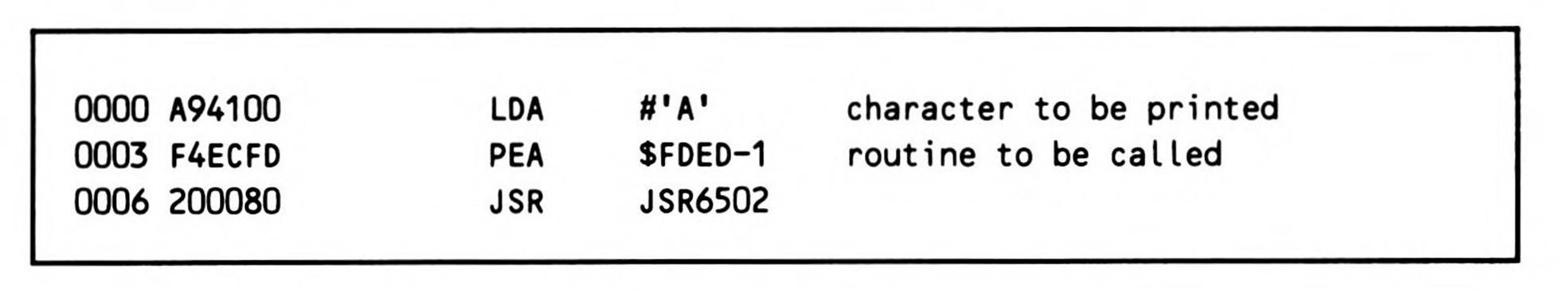
Fragment 14.4.
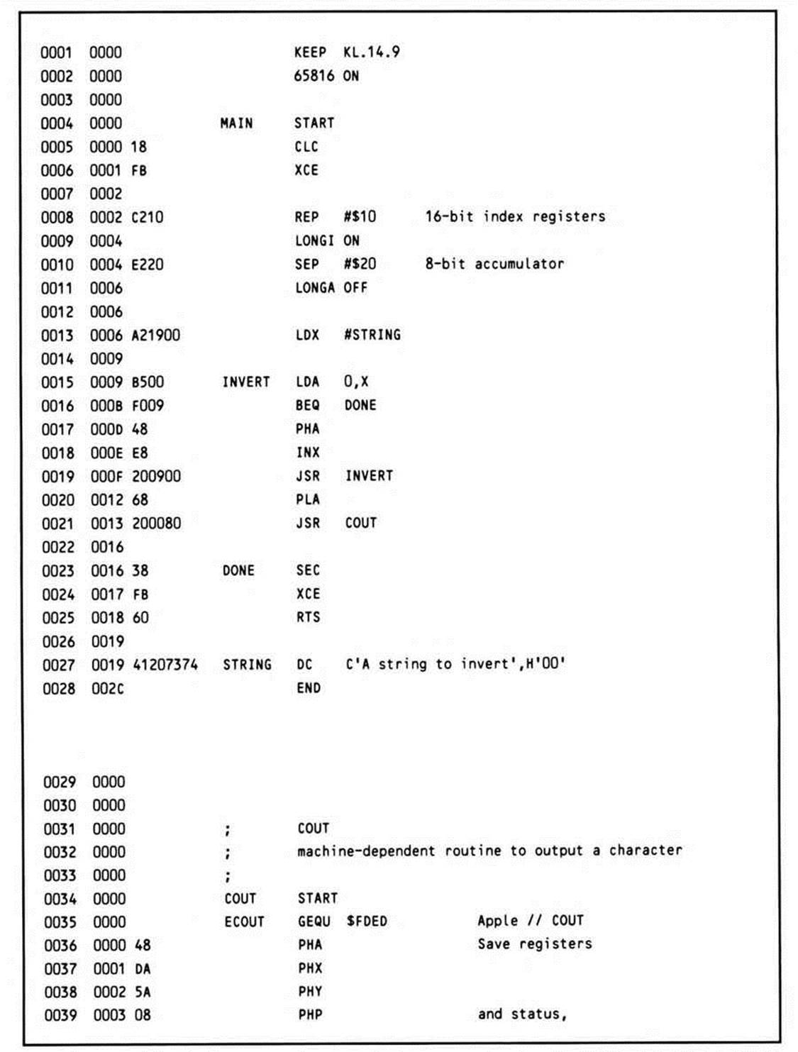
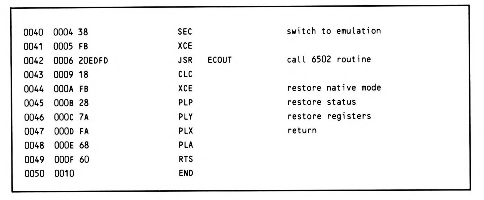
$FDED is the address of an existing Apple // routine to print characters, and JSR6502 is the routine described in Listing 14.5.
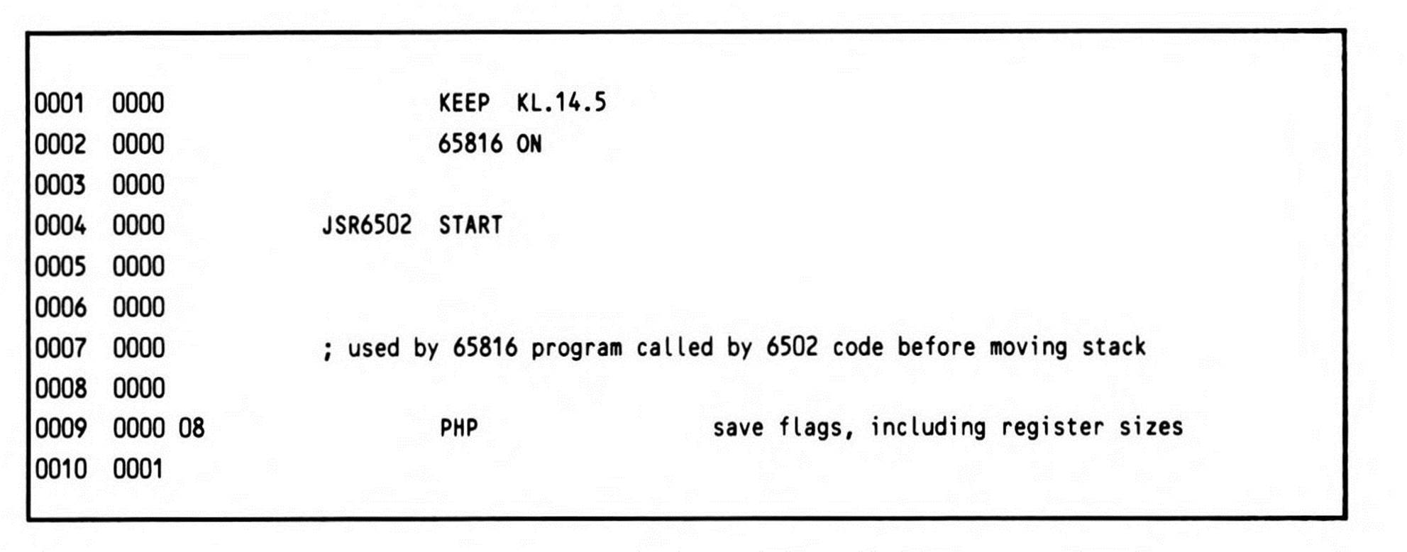
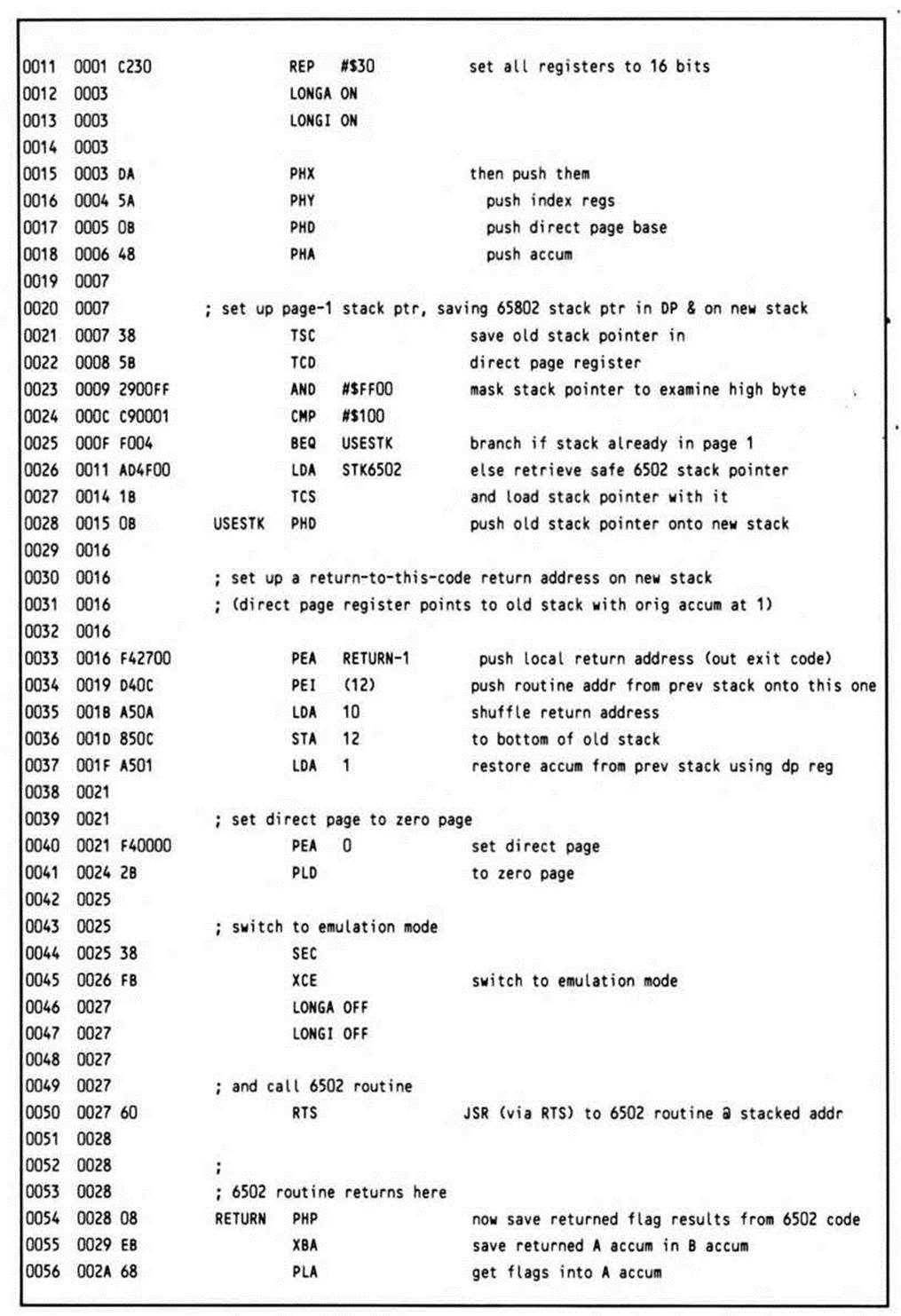
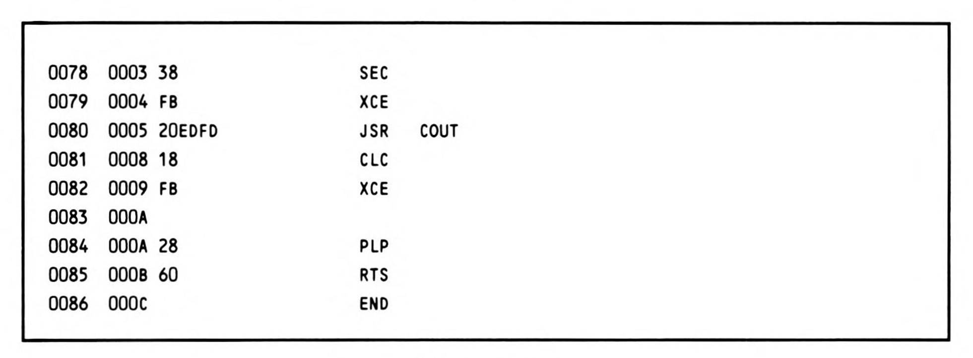
Listing 14.5.
The routine is entered with the return address on the top of the stack, and the go-to address of the 6502 routine at the next location on the stack. Since you want to be able to restore the m and x mode flags, the first thing the routine does is push the status register onto the stack. The REP #$30 instruction, which follows, puts the processor into a known state, since the routine can be called from any of the four possible register-size modes. The long accumulator, long index mode is the obvious choice because it encompasses all the others. The user registers, including the direct page register, are saved on the stack, and then the stack pointer itself is saved to the direct page register via the accumulator. This has two benefits: it preserves the value of the old stack pointer across a relocation of the stack, and provides a means of accessing all of the data on the old stack after it has been relocated. This technique is of general usefulness, and should be understood clearly. Figure 14.1, which shows the state of the machine after line 0034 (the PEI instruction), helps make this clear.
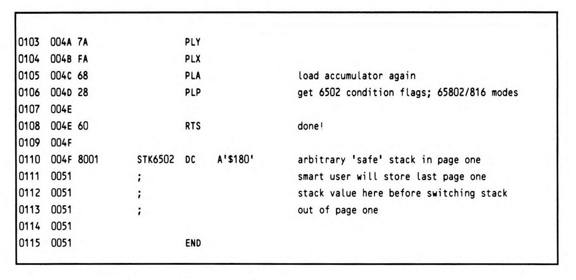
The stack must be relocated to page one only if it is not already there. If it is elsewhere, then the last 6502 page-one stack pointer should be restored from where it was cubbyholed when the 65802/65816 program took control and moved the stack elsewhere. If there is no previous 6502 stack to avoid, any page one address could be used to initialize the temporary 6502 stack needed.
The first item that goes onto the new stack is the value of the old stack pointer, now found in the direct page register. Next, a local return address must be pushed on the stack for when the called 6502 routine executes an RTS.
While the direct page register was pushed onto the new stack, it retains its value, and still points to the old stack; so although the stack pointer has been relocated, you still have access to the values on the old stack via direct page addressing. One of the needed items is the go-to address, the address of the 6502 routine to be called. Since the size of all of the elements pushed on the stack is known, by referencing the direct page location 12, this value is retrieved. A PEI (push indirect) instruction is used to transfer the routine to be called from the old stack (now being referenced via the direct page) to the new stack. This frees up the double byte on the old stack at dp:12.13, the bottom of the old stack; the return address is shuffled in from dp:10.11, freeing those two bytes.
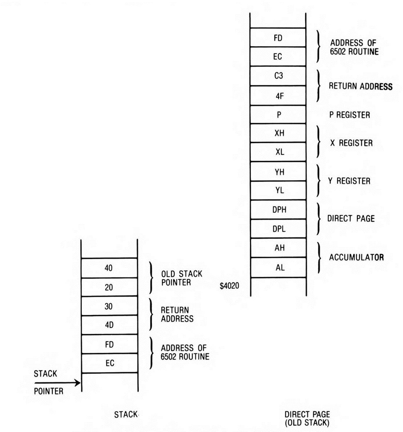
Figure 14.1. Stack Snapshot after PEI (12) Instruction.
The accumulator was used during these operations, and must be restored because it may contain one of the parameters required by the 6502 routine. Like the go-to address, the accumulator is loaded from the old stack using direct page addressing.
Having restored the accumulator, all that remains is to set the direct page register to zero; since no registers can be modified at this point, this is accomplished by pushing a zero onto the stack, and then pulling it into the direct page register.
When you switch the processor into emulation mode, the environment is as it should be; the new stack is now set up to transfer control to the 6502 subroutine via the execution of an RTS instruction which, rather than exiting the JSR6502 routine, performs a kind of jump indirect to the value on top of the stack, the go-to address. The use of the RTS to transfer control to the 6502 routine is the reason the address minus one is put on the stack to begin with. This requirement could be eliminated if the go-to address was decremented before being pushed on the page one stack; but this would require the execution of two additional instructions, one to load it into a register, and one to decrement. PEI moves the value directly onto the stack from the direct page.
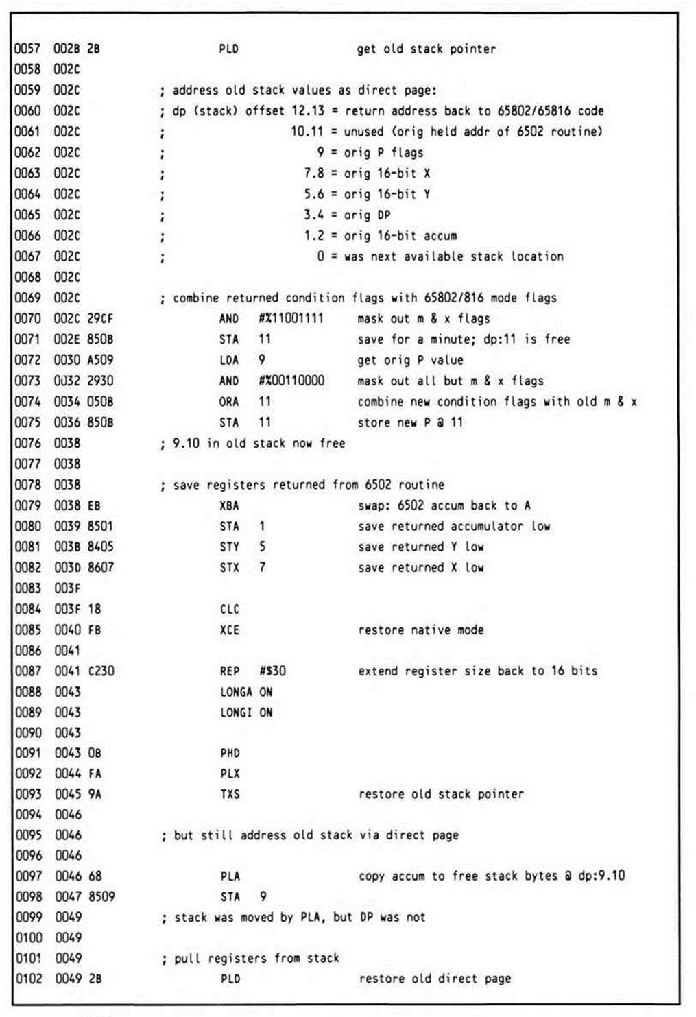
When control returns from the 6502 routine, the flags, representing the 6502 routine's results, are pushed, then pulled into the eight-bit A accumulator after its value has been saved by transferring it to the B accumulator with an XBA. The only other item left on the new stack is the old stack pointer. This is pulled into the direct page register, which immediately restores access to all of the values pushed onto the old stack.
The condition code bits in the returned status register are merged with the mode flags in the original status register. The eight-bit result is stored in the location immediately below the return address.
The register values upon return are saved into the locations where the registers were originally pushed on the stack. Since the processor is still in emulation mode, only the low bytes are stored; the high bytes of any of the 65802/65816 registers are always preserved (which means that if a low byte is unchanged, then the entire double-byte value is preserved).
The native mode is restored. The registers are extended to sixteen bits. The stack pointer is restored from the direct page register.
There remains a gap on the stack; the value of the accumulator is copied there. The registers are now restored, with the accumulator being pulled a second time from its new location.
Control is now back with the calling 65816 program, the processor never the wiser for having been transformed into a 6502.
This coding presumes that the calling code, the switching routine, and the 6502 routine are all located in the same bank, bank zero. It also assumes a data bank of zero. Should the 6502 routine be in a non-zero bank, then you should save its program bank to a safe location prior to the switch to emulation mode so that it cannot be lost in case of interrupt. You should also check your emulation mode interrupt service routines to be sure they restore the program bank from the safe location prior to returning.
Finally, should the calling code be in a bank different from the 6502 routine, you'll have to locate the switching code in the same bank with the 6502 routine (its return will be an RTS); call the switching code with a JSL; move the pushed program bank down two bytes to the bottom of the stack before relocating the return address; and return to the calling code via an RTL.
Testing Processor Type
A related utility routine (Listing 14.6) checks the processor type, allowing code targeted for the large 6502 installed-base to take advantage of a 65C02 or 65802/65816 if available. The processor is assumed to be in emulation mode if it is a 65816 or 65802.
This routine takes advantage of the fact that the 65C02 and 65816 set the sign flag correctly in the decimal mode, while the 6502 does not. The sign flag is set (minus) after loading $99 (a negative two's-complement number). When one is added to BCD 99, the result is BCD 0, a positive two's-complement number. On the 6502, adding one in decimal mode does not affect the sign flag. On the 65C02 and 65816, the sign flag is cleared to reflect that adding one results in a positive value (zero).
Having distinguished between the 65C02 and the 6502, the code further distinguishes between the 65C02 and 65816 by trying to execute one of the new 65816 instructions—specifically, the XCE instruction. If a 65C02 is in use, the execution of XCE has no effect; it simply performs a no-op, and the carry flag remains clear. On a 65816 in emulation mode, the carry flag would be set after exchanging.
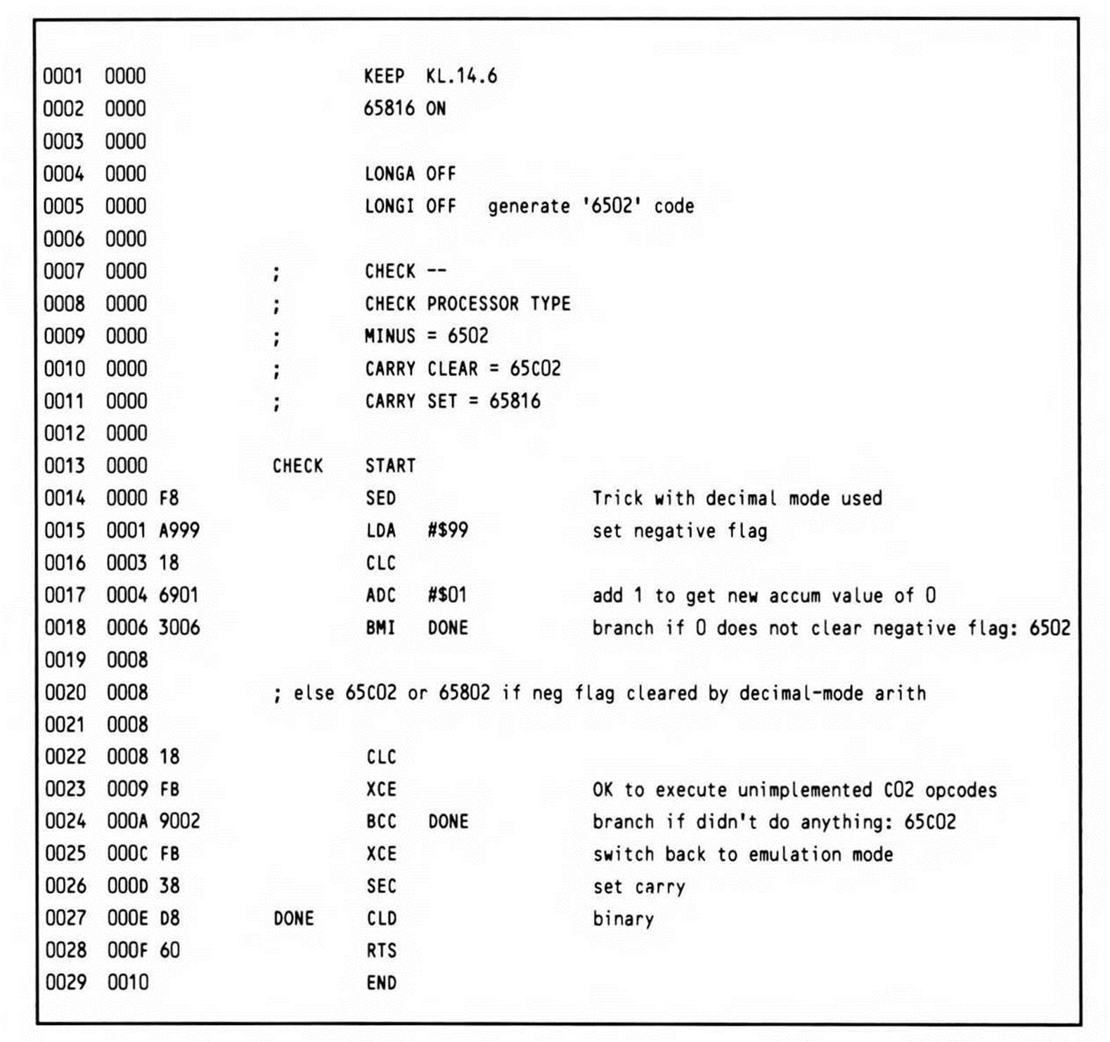
Listing 14.6.
Compiler-Generated 65816 Code for a Recursive Program
Although it is not directly relevant to assembly-language programming per se, a look at how a compiler might generate 65816 code provides another angle on 65816 program design. You may also find it helpful when you are writing in a high-level language to have some idea as to what kind of code your compiler might be generating.
For the brief example presented here, an integer-only subset of the C programming language—such as the dialect known as "small C"—is used. To understand C, it is important to understand the concept of the pointer. Effectively, a pointer is a variable that holds the address ofanother data structure. C programmers are particularly known for their liberal use of pointers, primarily because they provide a method to manipulate data structures that is very close to the machine level. The concept of the variable itself is an abstraction which generally results in additional overhead.
The most notable thing about the use of pointers in the example is that they are limited to sixteen bits, even though the 65816 has an address space of sixteen megabytes. The sixteen-bit machine word size was chosen both for pointers and for the storage type int; this lets many operations be implemented using one or two 65816 instructions. As a consequence, the memory model used with this compiler limits data storage to 64K; program storage is also limited to 64K. If the loader for this hypothetical compiler supports loading of constant data and program code into separate banks, a total of 128K memory would be available to the program.
The first line of the program, shown in Listing 14.7, is the declaration of the function main. By convention, the function main is always called as the entry point to a program; it typically (but not necessarily) is the first routine coded, as it is in this example.
The curly braces define the function block; the first statement in the block is the declaration of y, which is a pointer to a character; an asterisk before an identifier indicates that it is a pointer variable. In C, pointers are typed by the type of the data object to which they point.
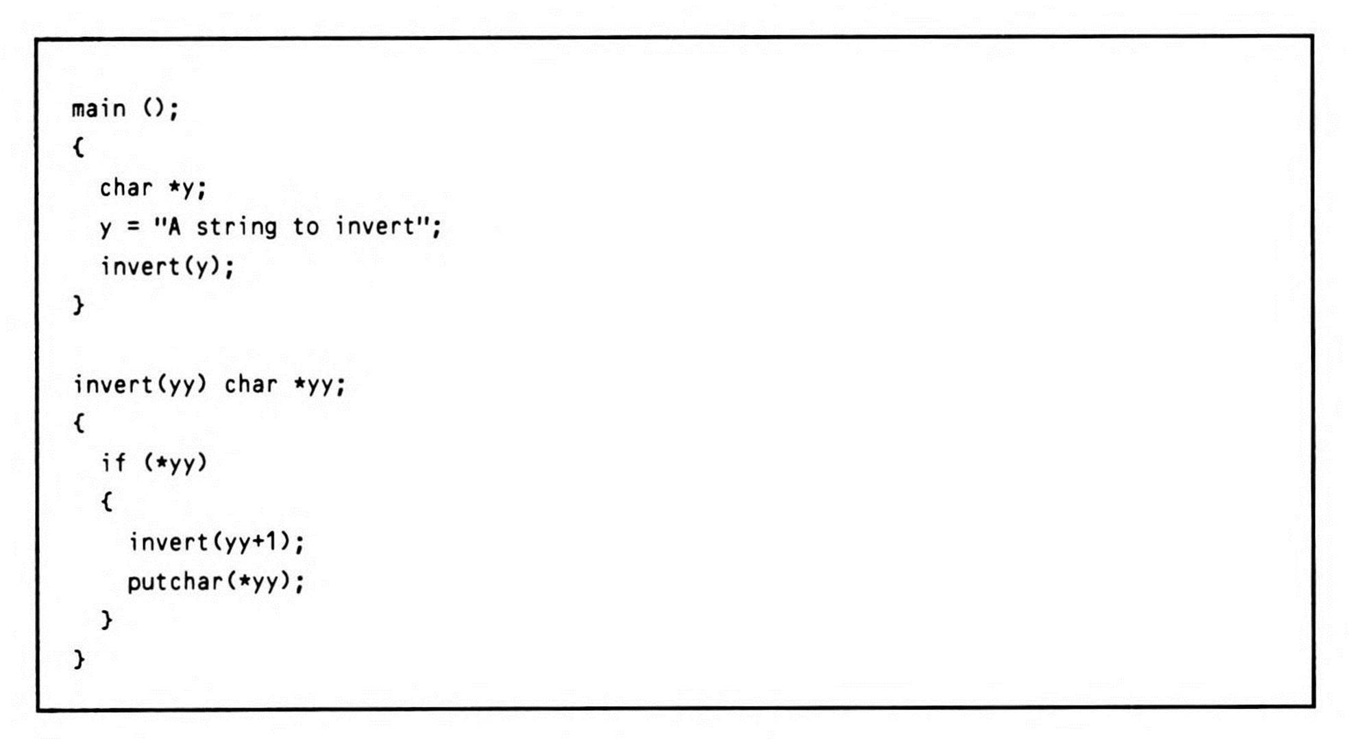
Listing 14.7.
The first executable statement is the assignment of the string constant “A string to invert" to the variable y. In this context, the y appears without the asterisk, because the variable is being given a value—an address—rather than the string it points to. The C compiler always returns the address of a string and zero-terminates it when it encounters a string constant.
The next statement is a call to the function invert with a parameter of y (which is the variable that just received a value in the preceding statement). Invert is the function that actually does the work of this program, which, as you may have guessed by now, prints an inverted (backwards) string.
After the closing brace for main comes the declaration of the function invert. Invert takes a parameter—a pointer to a character. When invert is called from main with y as the parameter, yy assumes the value of y.
The code of invert tests the value pointed to by yy; the first time invert is called, this will be the letter "A", the first character in the string constant. The test is whether or not the value "at yy" is non-zero or not; if it is non-zero, the statements within the braces will be executed. If (or when) the value is equal to zero, the code within the braces is skipped.
Looking at the first of the pair of lines contained within the braces, you will find that it is a call to invert—the same function presently being defined. This calling of a routine from within itself is called recursion, and programming languages such a C or Pascal, which allocate their local variables on the stack, make it easy to write recursive programs such as this one. The merits of using recursion for any given problem are the subject for another discussion; however, as seen in the example, it seems quite useful for the task at hand. What happens when this function calls itself will be explored in a moment, as the generated code itself is discussed.
The last executable line of the program calls the routine putchar, an I/O routine that outputs the value passed it as a character on the standard (default) output device.
Returning to the top of the program, Listing 14.8 shows the code generated by the compiler to execute the C program; it is inter-listed with the source code—each line of compiler source appears as an assembler-source comment.
Before the first statement is compiled, the compiler has already generated some code: a jump to a routine labeled CCMAIN. CCMAIN is a library routine that performs the "housekeeping" necessary to provide the right environment for the generated code to run in. At the very least, CCMAIN must make sure the processor is in the native mode, and switch into the default (for the compiler) sixteen-bit index and accumulator word sizes. If the operating system supports it, it should also initialize the variables argc and argv, which allow the programmer access to command-line parameters, although they are not used in this example. Finally, CCMAIN will call main to begin execution of the user-written code itself.
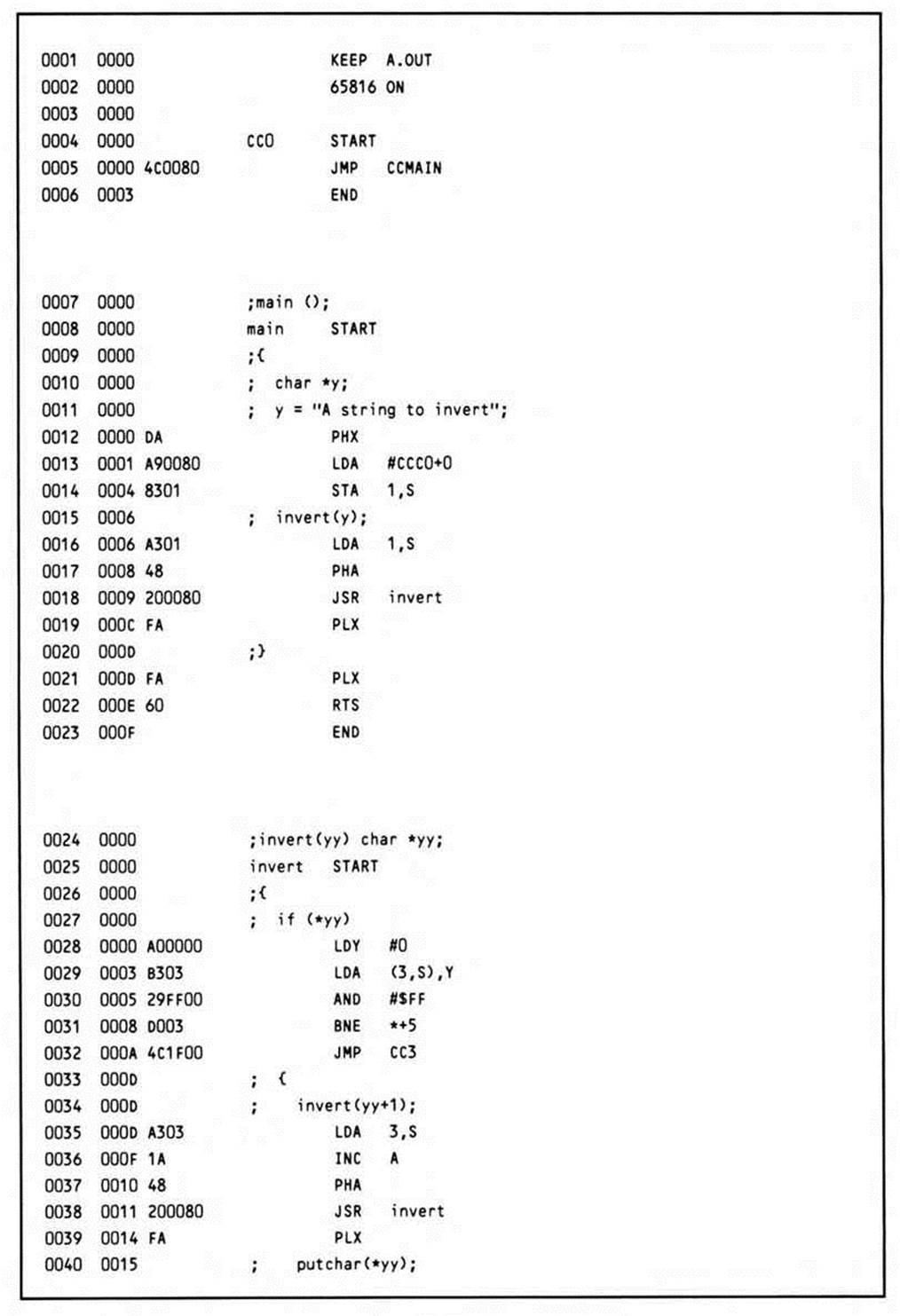
Listing 14.8.
The declaration of main causes an assembler START statement to be output; this simply defines the beginning of the subroutine or function. The declaration char *y will cause the PHX instruction to be generated after the first line of executable code is generated; this reserves space for one variable (the pointer y) on the stack. That first executable code line is the assignment y = "A string to invert". This causes the address of the string constant, which will be temporarily stored at the end of the generated program, to be loaded into the accumulator. The address just loaded into the accumulator is now stored on the stack in the memory reserved for it by the PHX instruction; the value of X that was pushed onto the stack was meaningless in itself.
The next statement to be compiled is a call to the function invert with the variable y as the parameter. This causes the value stored on the stack to be loaded back into the accumulator, where it is then pushed onto the stack. All parameters to function calls are passed on the stack.
Note that the accumulator already contained the value stored on the top of the stack; the LDA 1,S instruction was redundant. However, the hypothetical compiler in this example does not optimize across statements, so the potential optimization—elimination of the load instruction—cannot be realized. Once the parameter is on the top of the stack, the function itself is called via a JSR instruction. Since the program space is limited to 64K, only a sixteen-bit subroutine call is used. After the call returns, the PLX instruction removes the no-longer-needed parameter from the stack. The right bracket indicating the end of the function main causes the compiler to generate another PLX to remove the variable storage, an RTS instruction, and an assembler END statement.
Invert is defined as having one parameter, the character pointer yy. By declaring the function in this way, the compiler knows to generate code to look for the variable yy on top of the stack whenever a reference to it is made. You can see how this is done by looking at the code generated for the first line, which tests the value at yy (rather than the value of yy) to see whether it is true, that is, not equal to zero. To get this value, the stack relative indirect indexed addressing mode is used. First the Y register is loaded with zero, so that the first element pointed to by the indirect value on the stack is accessed. The stack offset used is three, rather than one, because when the subroutine call was made, after the parameter was pushed onto the stack, the return address was pushed onto the stack, on top of the parameter.
After the value is loaded, it must be ANDed with $FF to mask out the high-order contents, since this is a character (one-byte) type of variable.
If the character is not equal to zero, as it is not the first time through, the JMP CC3 instruction is skipped, and execution continues with the code generated for the C source statements inside the braces.
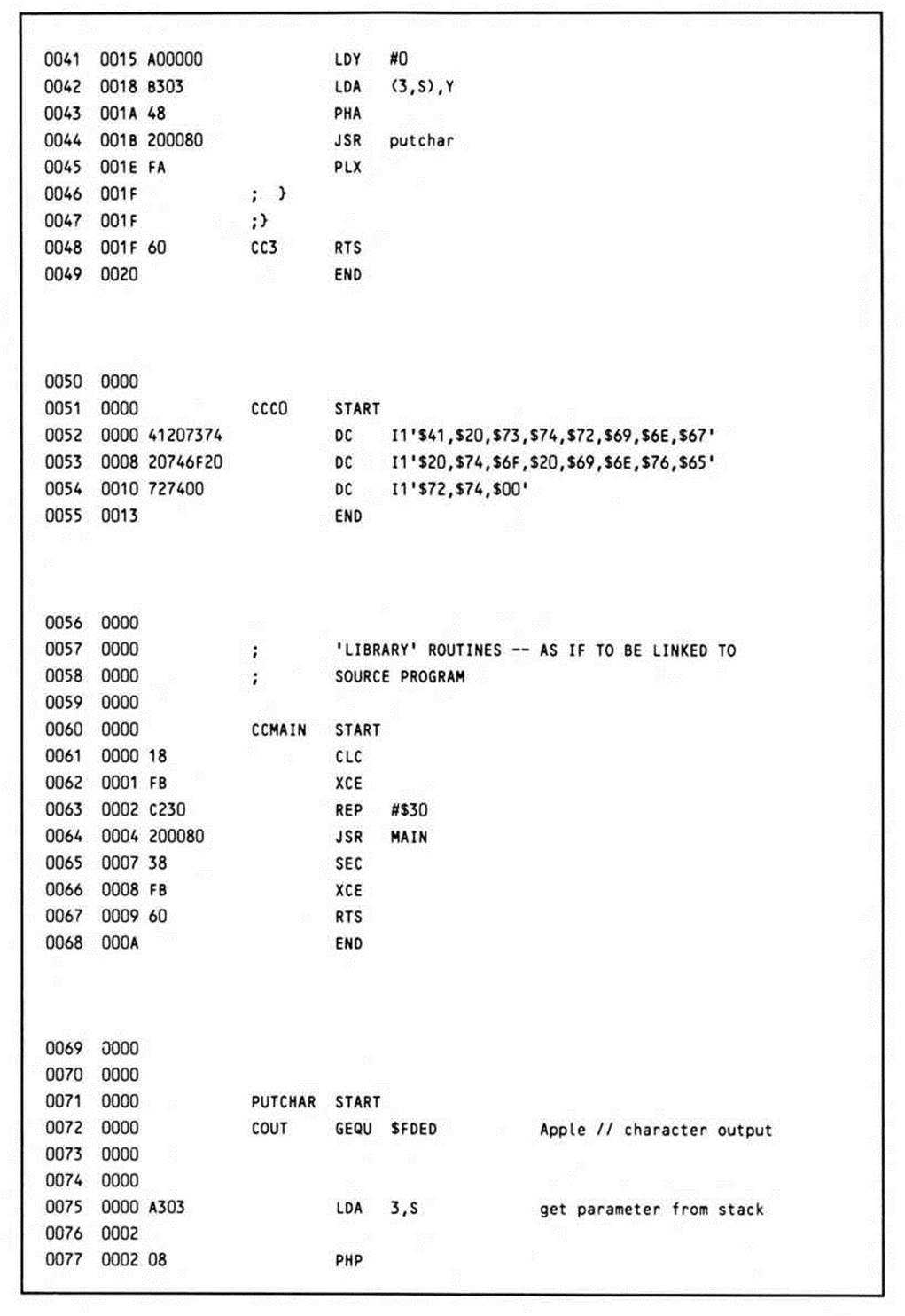
The first statement is the recursive call to invert. Similar to the call from main, a parameter is pushed onto the stack. Since an expression (yy + 1) is being passed, however, it must first be evaluated. First the value of yy is loaded from the stack, and then one is added to it. Although this hypothetical compiler does not optimize across statements, it apparently does a pretty good job within them, for it has optimized the addition of one to a single increment instruction.
Invert is then called again. If you start counting them, you will find that more pushes than pulls will have been made at this point; in other words, the stack is growing. When invert is reentered, the value it finds on the stack is the starting address of the string literal plus one; in other words, the second element is being addressed. As long as the value pointed to by the parameter passed to invert is non-zero, invert will continue to be called recursively, and the stack will continue to grow. When the last element (with the value of zero) is reached, the recursive function "bottoms out"; the jump to CC3 that occurs when the value at yy is equal to zero jumps directly to an RTS instruction. This causes control to return to the next statement after the call to invert. The value of yy in the most recently called invocation (the value at 3,S) will be a pointer to the last character in the string; it is this character that is first loaded into the accumulator, then pushed, output via a call to the routine putchar, then pulled again.
Upon return from putchar, control falls through to the RTS instruction, and the next set of values on the stack are processed. This continues until all of the characters pointed to by the values on the stack have been printed, in the reverse order in which they were found. Finally, the last return executed pulls the address of the return address in main off the stack, and the program terminates.
The Same Example Hand-Coded in Assembly Language
A distinctive characteristic of the preceding high-level language programming example was that the algorithm employed involved recursion. Consider Listing 14.9, which is the same algorithm hand-coded in assembly language; it is much more efficient than the compiler-generated example.
Listing 14.9.
Because the more elaborate parameter-passing and variable-allocation requirements of the C language can be bypassed, the example here is much more efficient. (Although some further optimization of the compiler-generated code, as noted, is possible, the code in the example would probably be a typical result.)
To start with, a more intelligent decision about the mode flags is made right from the start, rather than coping with the default sixteen-bit accumulator size of the compiler code by masking out the high-order byte whenever a character is loaded.
Secondly, full use of the index register is made, both to access the data and as the parameter-passing mechanism. Rather than push successive pointers to the inverted character string on the stack, the character itself is stored.
If this routine will be used to invert a single, known string (as opposed to making INVERT a subroutine for inverting any string, the beginning character of which is pointed to by the X register), then any assembly language programmer would simply write the code found inListing 14.10. When the assembler evaluates the LDX instruction's operand, the "L:" function determines the length of STRING.
The Sieve of Eratosthenes Benchmark
With all of the different factors that affect system performance, it is difficult to find a clear criterion by which to judge a processor's performance. Rightly or wrongly, the speed with which a processor runs a standard "benchmark" program is often used in forming a judgement of it. One of the most commonly used (and cited) benchmarks is the Sieve of Eratosthenes algorithm. The use of the Sieve program first gained popularity as the result of articles written by Jim Gilbreath and Gary Gilbreath, appearing in BYTE magazine (September 1980, page 180), and updated in January 1983 (page 283).
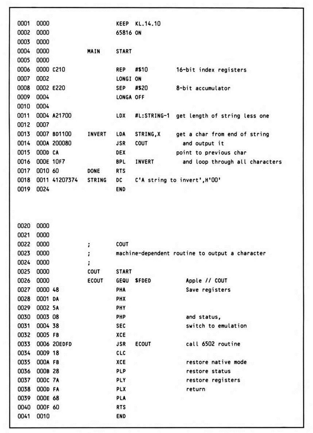
Listing 14.10.
The Sieve program calculates the prime numbers between 3 and 16,381; it is based on an algorithm originally attributed to the Greek mathematician Eratosthenes. The basic procedure is to eliminate every nth number after a given number n, up to the limit of range within which primes are desired. Presumably the range of primes is itself infinite.
As well as providing a common yardstick with which to gauge the 65816, the Sieve program in Listing 14.11 provides an opportunity to examine performance-oriented programming; since the name of the game is performance, any and all techniques are valid in coding an assembly-language version of a benchmark.
Four variable locations are defined for the program. ITER counts down the number of times the routine is executed; to time it accurately, the test is repeated 100 times. COUNT holds the count of primes discovered. K is a temporary variable. And PRIME is the value of the current prime number.
The variable I has no storage reserved for it because the Y register is used; it is an index counter. Y is used instead of X because certain indexed operations need the absolute,X addressing mode.
The constant SIZE is equal to one-half of the range of numbers within which the primes are to be discovered; this algorithm ignores all even numbers (even numbers being non-prime). The first element in the array represents 3, the second 5, the third 7, and so on.
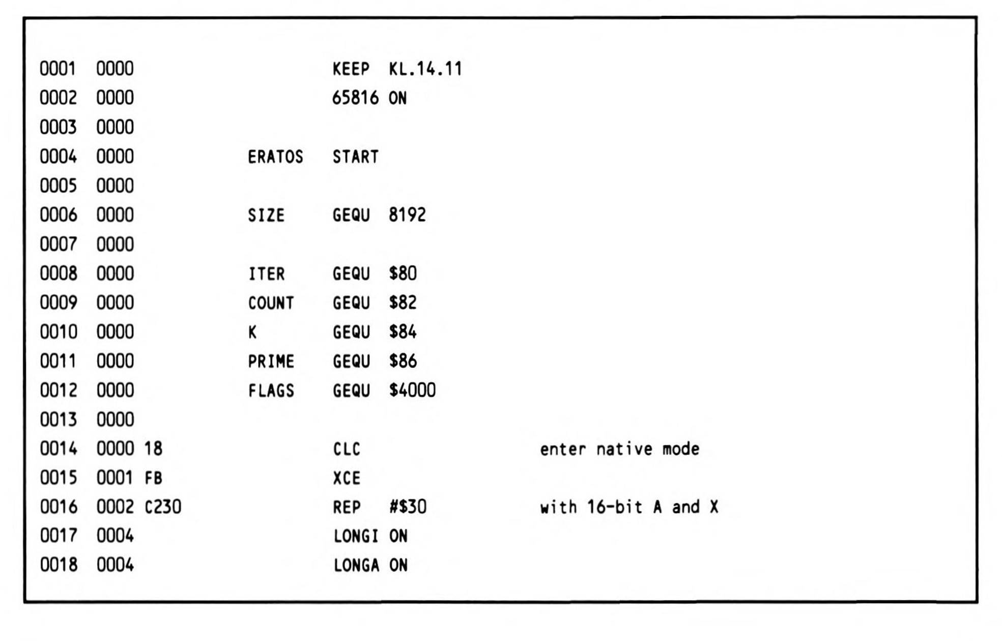
Listing 14.11.
The program begins by entering the native mode and extending the user registers to sixteen bits. ITER is initialized for 100 iterations. An array (starting at FLAGS) of memory of size SIZE is initialized to SFF's, two bytes at a time.
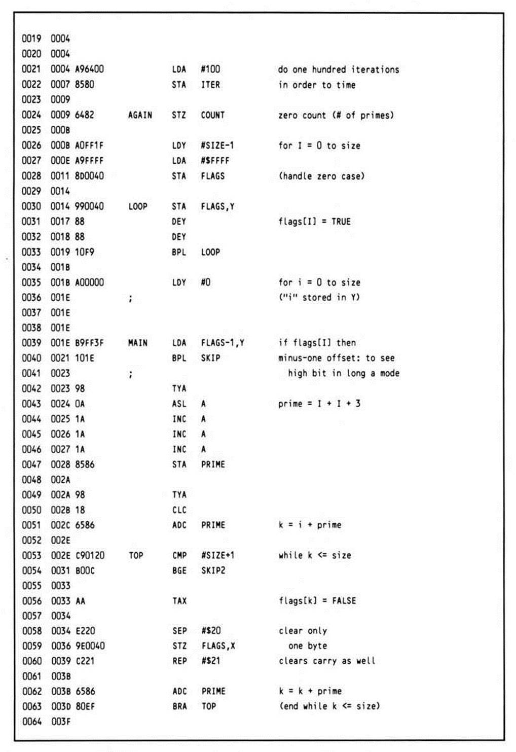
The routine proper now begins. Y is initialized with zero, and control falls into the main loop. The high-order bit of each cell of the array FLAGS is tested. Initially, they are all set, but the algorithm iteratively clears succeeding non-prime values before they are tested by this code. If the high bit is clear, this number has already been eliminated by the algorithm; it is non-prime. Notice that the high-order bit of the FLAG[I] (or FLAG[Y]) array is desired; however, since the processor is in sixteen-bit mode, the high bit will be loaded from the memory location at the effective address plus one. To overcome this, the base of the array is specified as the actual base minus one; this calculation is performed by the assembler during generation of the object code.
If the current value has not been cleared, the algorithm calls for the number which is two times the current index value plus three (this converts the index to the array values of 3, 5, 7. . . ) to be the next value for PRIME. This prime number is generated quickly by transferring the Y index register into the accumulator, shifting it left once to multiply by two, and incrementing it three times. Remember, this number is generated from the current index only if the index value has not already been eliminated as being non-prime.
This prime number is then added to the current index, and the array elements at this offset, and at all succeeding indices every PRIME value apart are eliminated from the array as being non-prime. They have the current prime number as one of their factors. The most significant thing to note here in the code is that only one byte can be cleared; the accumulator must temporarily be switched into the eight-bit mode to accomplish this. However, since the next operation is an addition, an optimization is available: both the sixteen-bit mode can be restored and the carry cleared in a single REP operation.
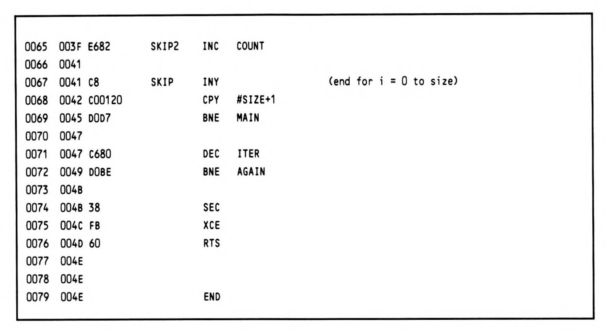
The program now loops, checking to see if the next index value has been eliminated; this process continues until the index reaches the limit of SIZE.
You may be wondering what the result is: at 4 MHz, ten iterations are completed in 1.56 seconds, which is twice as fast as a 4 MHz 6502. The January, 1983 BYTE article cites results of 4.0 seconds for a 5 MHz 8088, 1.90 seconds for an 8 MHz 8086, and .49 seconds for an 8 MHz 68000; an 8 MHz 65816 would yield .78 seconds.
All materials on the site are licensed Creative Commons Attribution-Sharealike 3.0 Unported CC BY-SA 3.0 & GNU Free Documentation License (GFDL)
If you are the copyright holder of any material contained on our site and intend to remove it, please contact our site administrator for approval.
© 2016-2026 All site design rights belong to S.Y.A.