Programming the 65816 Including the 6502, 65C02, and 65802 (1986)
Appendices
D. Instruction Groups
The 65x instructions can be divided into three groups, on the basis of both the types of actions of each instruction and the addressing modes each can use. The opcodes in the first group and some in the second have similar bit patterns, the same addressing modes available, and regularity which can make remembering the capabilities of a particular instruction—or creating a compiler code generator—much easier.
Group I instructions are the most commonly used load, store, logic, and arithmetic instructions, and have by far the most addressing modes available to them. Group II instructions are mostly read-modify-write instructions, such as increment, decrement, shift, and rotate, which both access and change one and only one register or memory location.
Group III is a catch-all for the remaining instructions, such as index register comparisons and stack operations.
Group I Instructions
The 65x Group I instructions, with their opcode's bit patterns, are shown in Table D.1. The 'aaaaa's are filled with addressing mode bit patterns—there is one pattern for each addressing mode available to Group I instructions.
Table D.1. Group I Instructions Opcode Patterns.
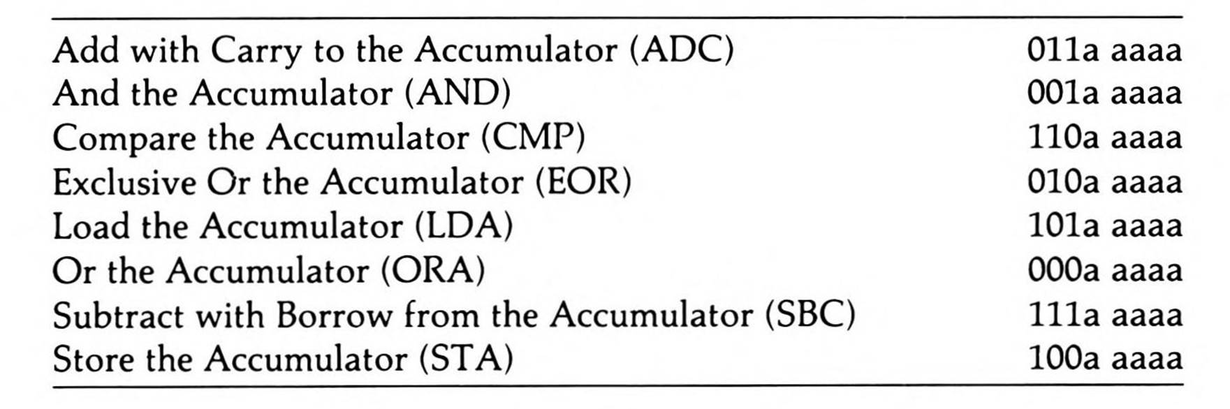
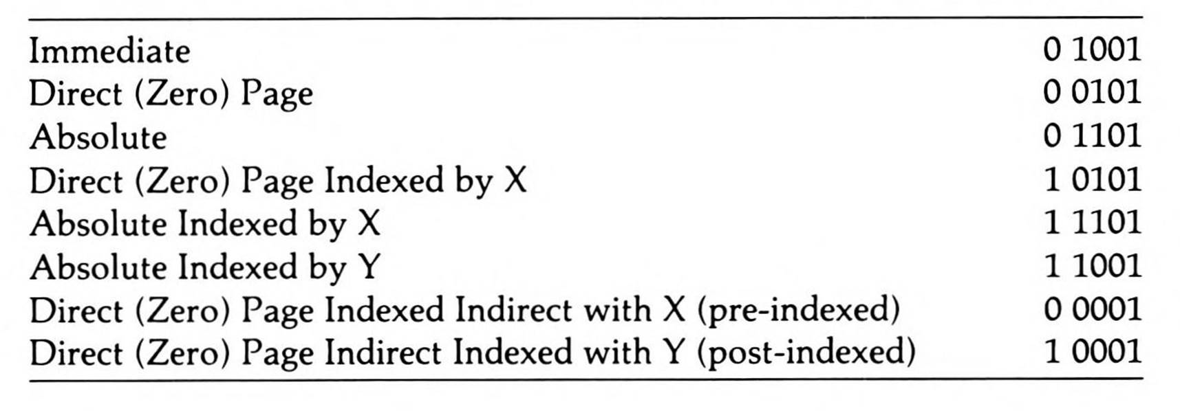
The 6502 addressing modes available to the Group I instructions have bit patterns that all end in '01'. These bit patterns are found in Table D.2. The exception to this scheme is STA immediate; since it is not possible to use immediate addressing with a store instruction, its logical opcode 1000 1001 is used by a non-Group-I instruction.
Table D.2. Address Mode Patterns for Group I Instructions.
The 65C02 adds one more addressing mode for Group I instructions; it has the only Group I addressing mode bit pattern to end in a zero:
|
Direct (Zero) Page Indirect |
10010 |
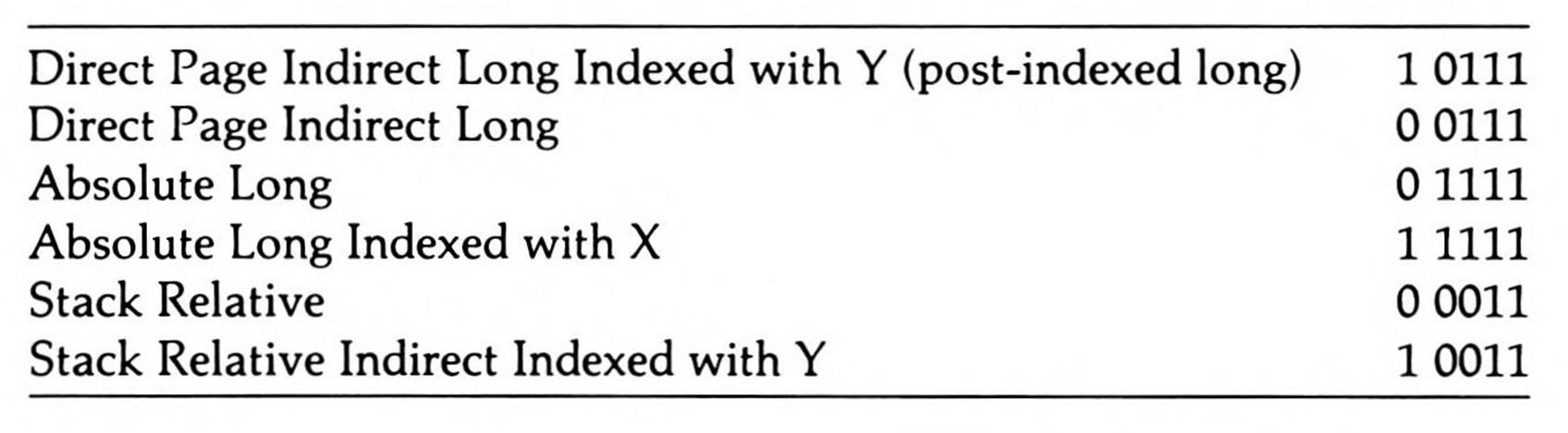
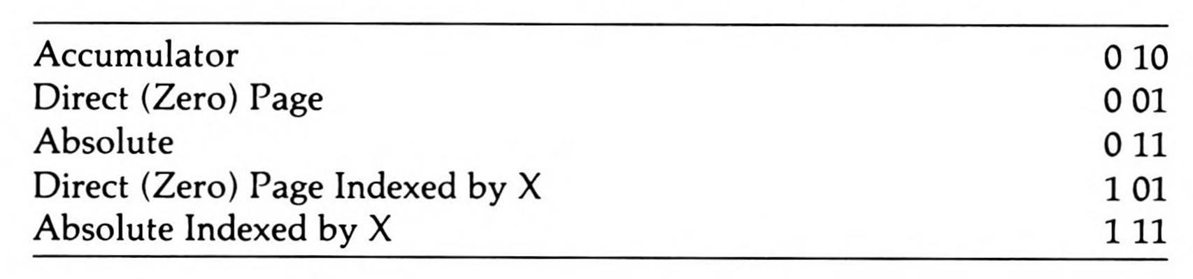
The 65802 and 65816 add the six addressing modes for Group I instructions found in Table D.3.
Table D.3. 65802/65816 Group I Addressing Mode Patterns.
Group II Instructions
Group II instructions are an amalgam of mostly read-modify-write instructions with very similar addressing modes (differing only whether they have accumulator addressing available to them on the 6502). The instructions, with their opcode bit patterns, are listing in Table D.4.
There are either four or five addressing modes available to these instructions on the 6502—five if the missing bits are 'bbc' rather than just 'bb', the fifth addressing mode being accumulator addressing.
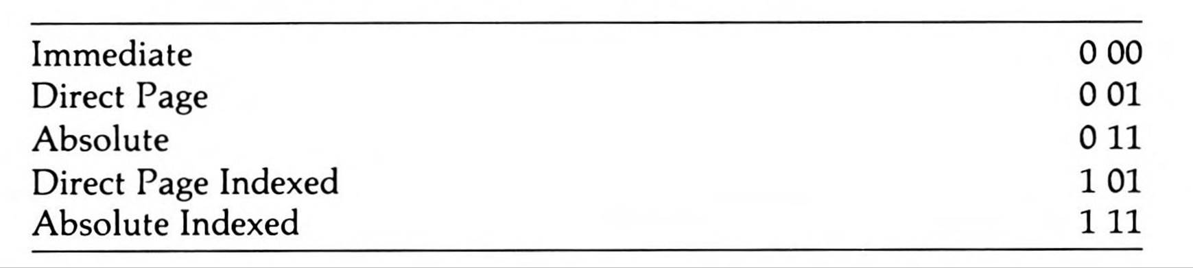
Table D.5 shows the five addressing modes with their bit patterns. All three bits in this table are filled into the 'bbc' missing bits in Table D.4; only the first two bits of each Table D.5 set are filled into 'bb' missing bits in Table D.4.
Table D.4. Group II Opcode Patterns.
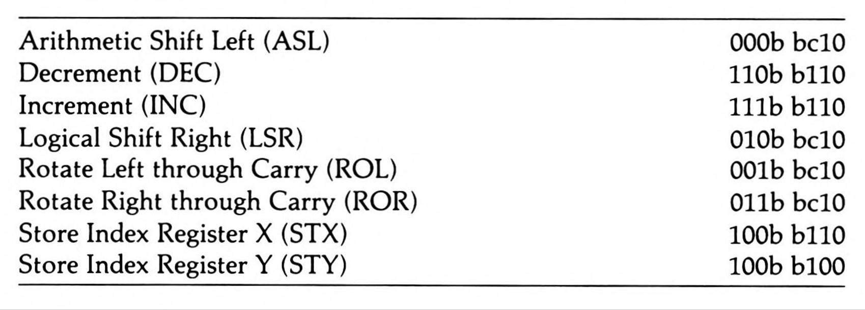
Table D.5. Address Mode Patterns for Group II Instructions.
Notice how the four 'bbl' addressing modes have the same bit patterns as the first three bits of their corresponding bit patterns for the Group I instruction addressing modes.
There are a few exceptions.
Absolute indexing is not available for storing either index register. Furthermore, since the register cannot use itself to store itself, the STX instruction can't use direct page,X; instead, direct page,Y substitutes for this instruction's direct page, indexed store.
The two 65C02 instructions to increment and decrement the accumulator do not follow this scheme at all; giving these instructions that addressing mode clearly was not planned when the 6502 was designed, since their opcodes were assigned to other instructions. Nor does the 65C02's STZ (store zero to memory) instruction, which uses the main four addressing modes, follow the scheme, even though it seems clearly to be a Group II instruction of this type. But four of the five addressing modes of the BIT instruction on the 65C02, 65802, and 65816 (the 6502 has only two addressing modes for this instruction)—the four 'bbl' addressing modes above—follow this scheme (its bit pattern is 001b blOO). It also has an immediate addressing mode, however, which is in no way regular.
Loading the Index Registers
The two index registers can be loaded with regular opcodes:
|
Load Index Register X (LDX) |
lOld ddlO |
|
Load Index Register Y (LDY) |
101d dd00 |
Available to them are the five addressing modes in table D.6.
Table D.6. Address Mode Patterns for Load Index
Register Instructions.
The two indexed modes use the Y index register for indexing when loading the X register and vice versa.
Index Register Compares
The two instructions to compare an index register to memory have three addressing modes available to them.
The instructions are:
Compare Index Register X with Memory (CPX) 1110 ee00
Compare Index Register Y with Memory (CPY) 1100 ee00
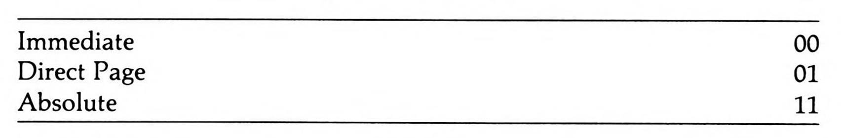
Table D.7 lists the three addressing modes available.
Table D.7. Address Mode Patterns for Compare Index Register Instructions.
Test-and-Change-Bits Instructions
The two test-and-change-bits instructions each have two addressing modes that they use in a regular manner.
The two instructions are:
|
Test and Reset Memory Bits (TRB) |
0001 x100 |
|
Test and Set Memory Bits (TSB) |
0000 x100 |
|
The two addressing modes are: |
|
|
Direct Page |
x = 0 |
|
Absolute |
x = 1 |
All materials on the site are licensed Creative Commons Attribution-Sharealike 3.0 Unported CC BY-SA 3.0 & GNU Free Documentation License (GFDL)
If you are the copyright holder of any material contained on our site and intend to remove it, please contact our site administrator for approval.
© 2016-2026 All site design rights belong to S.Y.A.