Programming the 65816 Including the 6502, 65C02, and 65802 (1986)
Part II. Architecture
2. Architecture of the 6502
This chapter, and the two which follow, provide overviews of the architecture of the four 65x family processors: the 6502, the 65C02, and the 65802/65816. Each chapter discusses the register set and the function of the individual registers, the memory model, the addressing modes, and the kinds of operations available for each respective processor. Because each successive processor is a superset of the previous one, each of the next two chapters will build on the material already covered. Much of what is discussed in this chapter will not be repeated in the next two chapters because it is true of all 65x processors. As the original 65x machine, the 6502 architecture is particularly fundamental, since it describes a great number of common architectural features.
Microprocessor Architecture
The number, kinds, and sizes of registers, and the types of operations available using them, defines the architecture of a processor. This architecture determines the way in which programming problems will be solved. An approach which is simple and straightforward on one processor may become clumsy and inefficient on another if the architectures are radically different.
A register is a special memory location within the processor itself, where intermediate results, addresses, and other information which must be accessed quickly are stored. Since the registers are within the processor itself, they can be accessed and manipulated much faster than external memory. Some instructions perform operations on only a single bit within a register; others on two registers at once; and others move data between a register within the processor and external memory. (Although the registers are indeed a special kind of memory, the term memorywill be used only to refer to the addressable memory external to the microprocessor registers.)
The 6502 is not a register-oriented machine. As you will see, it has a comparatively small set of registers, each dedicated to a special purpose. The 6502 instead relies on its large number of addressing modes, particularly its direct-page indirect addressing modes, to give it power.
An addressing mode is a method, which may incorporate several intermediate calculations involving index registers, offsets, and base addresses, for generating an instruction's effective address—the memory address at which data is read or written. Many 6502 instructions, such as those for addition, have many alternate forms, each specifying a different addressing mode. The selection of the addressing mode by you, the programmer, determines the way in which the effective address will be calculated.
There are three aspects to learning how to program the 6502 or any processor. Learning the different addressing modes available and how to use them is a big part. Learning the available instructions and operations, such as addition, subtraction, branching and comparing, is another. But to make sense of either, you must begin by understanding what each of the different registers is and does, and how the memory is organized.
If you compare the different processors in the 65x family—the eight-bit 6502 and 65C02 and the sixteen-bit 65816 and 65802—you will find they all have a basic set of registers and a basic set of addressing modes in common: the 6502's.
The 6502 Registers
The 6502 registers are:
•The accumulator, or A register, is the primary user register and generally holds one of the operands, as well as the result, of any of the basic data-manipulation instructions.
•The X and Y index registers are used chiefly in forming effective addresses for memory accesses and as loop counters.
•The processor status, or P, register contains bit-fields to indicate various conditions, modes, and results within the processor.
•The stack pointer, or S register, is a pointer to the next available location on the system stack, a special area of memory for temporary data storage. In addition to being available to the user, the stack pointer and stack are also used automatically every time a subroutine is called or an interrupt occurs to store return information.
•Finally, the program counter, or PC, is a pointer to the memory location of the instruction to be executed next.
These six basic 6502 registers are depicted in the programmer model diagrammed in Figure 2.1. Notice that, with the exception of the program counter (PC), all of them are eight-bit registers. Because they can contain only eight bits, or one byte, of data at a time, they can only perform operations, such as addition, on one byte at a time. Hence the 6502 is characterized as an "eight-bit" processor.
Although the user registers of the 6502 are only eight bits wide, all of the external addresses generated are sixteen bits. This gives the 6502 an address space of 64K (216 = 65,536). In order to access data located anywhere in that 64K space with an eight-bit processor, one instruction operand in calculating effective addresses is almost always found in memory—either in the code itself following an instruction, or at a specified memory location—rather than in a register, because operands in memory have no such limits. All that is needed to make a memory operand sixteen bits are two adjacent memory locations to put them in.
To allow programs longer than 256 bytes, the program counter, which always points to the location of the next instruction to be executed, is necessarily sixteen bits, or two bytes, wide. You may therefore locate a 6502 program anywhere within its 64K address space.
Now each of the 6502 registers will be described in more detail.
The Accumulator
The accumulator (A) is the primary register in a 65x processor. Almost all arithmetic and most logical operations are performed on data in the accumulator, with the result of the operation being stored in the accumulator. For example, to add two numbers which are stored in memory, you must first load one of them into the accumulator. Then you add the other to it and the result is automatically stored in the accumulator, replacing the value previously loaded there.
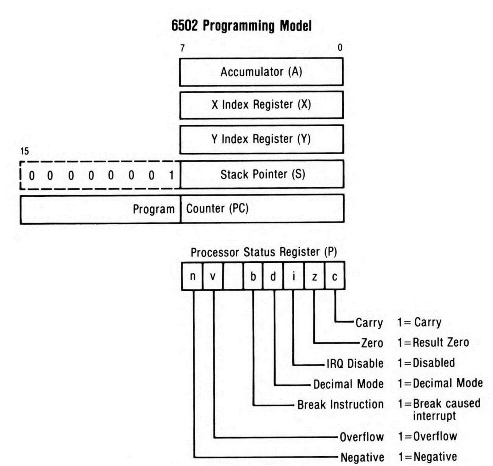
Figure 2.1. 6502 Programming Model.
Because the accumulator is the primary user register, there are more addressing modes for accumulator operations than for any other register.
The 6502 accumulator is an eight-bit register. Only one byte is ever fetched from memory when the accumulator is loaded, or for operations which use two values—one from memory and the other in the accumulator (as in the addition example above).
The X and Y Index Registers
The index registers are generally used either as components in generating effective addresses when any of the indexed addressing modes are used, or as loop counters. They can be easily incremented or decremented; that is, the value in the index registers can, by means of a single instruction, be increased or decreased by the number one. They are, therefore, useful in accessing successive table locations, moving memory, and counting loop iterations. Unlike the accumulator, no logical or arithmetic operations (other than incrementing, decrementing, and comparing) may be performed upon them.
The use of indexing allows easy access to a continuous series of memory locations, such as a multiple-byte, binary floating-point number, or an array of many single- or multiple-byte objects. Indexing is performed by adding one of several forms of base addresses, specified in the operand field of an instruction, to the contents of an index register. While a constant operand is fixed when a program is created, the index registers are variable and their contents can be changed readily during the execution of a program. As a result, indexing provides an extremely flexible mechanism for accessing data in memory.
Although the X and Y index registers are basically similar, their capabilities are not identical. Certain instructions and addressing modes work only with one or the other of these registers. The indirect indexed addressing modes require the Y register. And while the X register is primarily used with direct page indexed and absolute indexed addressing, it has its own unique (though infrequently used) indexed indirect addressing mode. These differences will become clear as you learn more about the different addressing modes.
The Status Register
The status register (also called the P register, for processor status) contains a number of flags which describe, in part, the status of the microprocessor and its operations. A flag is, in this case, a single bit within the status register. Its value, set (a one) or reset (a zero), indicates one of two conditions. While the 6502's eight-bit status register could provide eight one-bit flags, only seven of them are used.
Figure 2.1 showed the 6502 P status register; Tables 2.1 and 2.2 describe the functions of its flags.
Table 2.1 describes the five status register condition code flags—negative, zero, overflow, carry, and break. Their values indicate various conditions that result from the execution of many 6502 instructions. Some instructions affect none of the condition code flags, others affect only some, and still others affect all. The effect that an instruction has on the condition flags is an important part of describing what the instruction does. These condition code flags are used to determine the success or failure of the branch on condition instructions.
Notice particularly the zero flag (z). It can sometimes confuse assembly programmers because a zero flag setting of one indicates a zero result while a zero flag setting of zero indicates a non-zero result.
Table 2.1. Status Register Condition Code Flags.
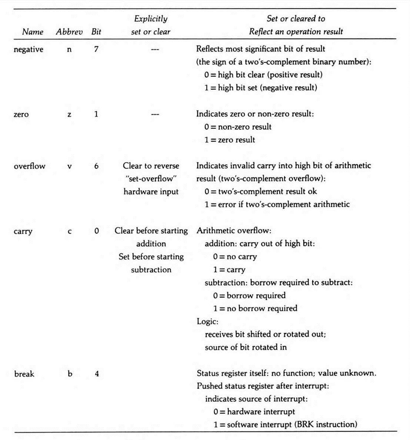
In connection with the carry flag, it is important to know that the 6502 add operation has been designed to always add in the carry, and the subtract operation to always use the carry as a borrow flag, making it possible to do multiple-precision arithmetic where you add successively higher sets of bytes plus the previous add's carry or subtract successively higher sets of bytes taking into the operation the previous subtract's borrow. The drawback to this scheme is that the carry must be zeroed before starting an add and set before starting a subtraction.
In the case of subtraction, the 6502's carry flag is an inverted borrow, unlike that of most other microprocessors. If a borrow occurred during the last operation, it is cleared; if a borrow did not result, it is set.
Finally, notice that in the status register itself, the break bit has no function. Only when an interrupt pushes the status register onto the stack is the break bit either cleared or set to indicate the type of interrupt responsible.
Table 2.2 describes the other two P register flags, the mode select flags: by explicitly setting or clearing them, you can change the operational modes of the processor.
Table 2.2. Status Register Mode Select Flags.
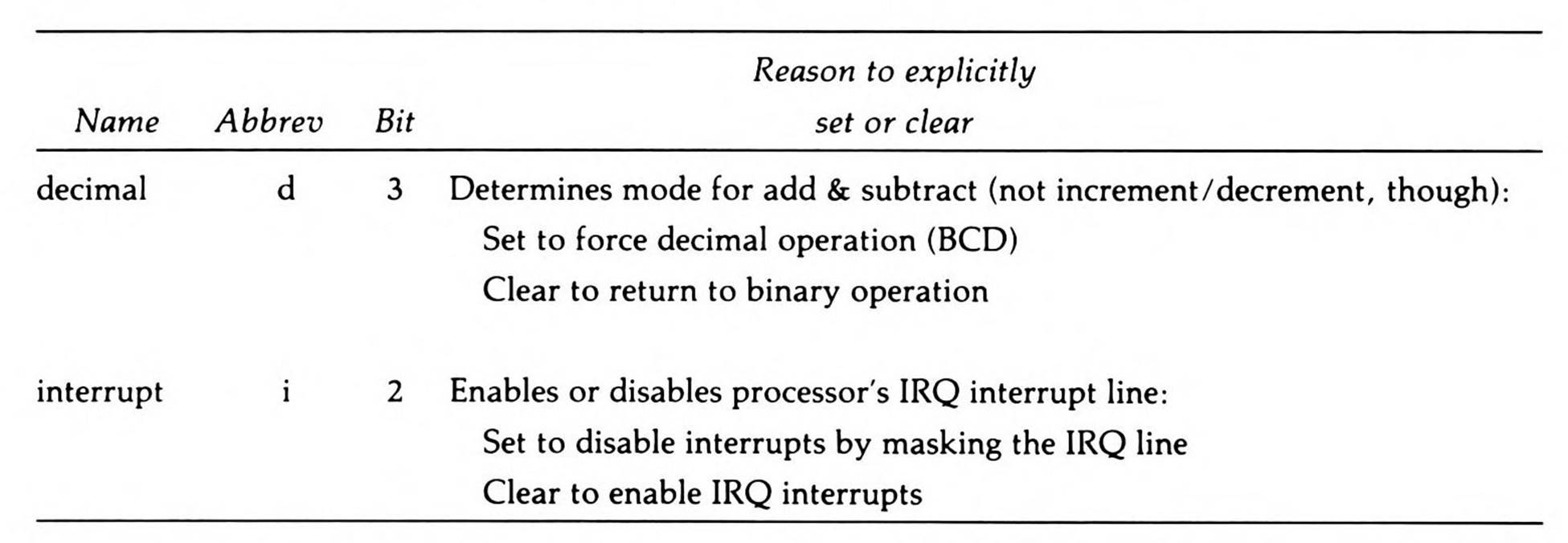
The decimal mode flag toggles add and subtract operations (but not increment or decrement instructions) between binary and decimal (BCD). Most processors require a separate decimal-adjust operation after numbers represented in decimal format have been added or subtracted. The 65x processors do on-the-fly decimal adjustment when the decimal flag is set.
The IRQ disable or interrupt disable flag, toggles between enabling and disabling interrupts. Typically, the interrupt mask is set during time-critical loops, during certain I/O operations, and while servicing another interrupt.
The Stack Pointer
The stack pointer (S) implements directly in hardware a data structure known as a stack or push-down stack. The stack is a dedicated area of memory which is accessed by the user via push and pull instructions. Push stores the contents of a register onto the stack; pull retrieves a data item from the stack, storing it into a register.
The 6502's stack is limited to 256 bytes by the eight-bit width of its stack pointer. The chip confines it in memory between $100 and $1FF by fixing the high-order byte of the stack address at $01. Software power-up routines generally initialize the 6502 stack pointer to $FF, resulting in an initial stack location of $1FF (see Figure 2.2).
Initializing the Stack Pointer to $FF:
Resulting Initial Stack of $1FF
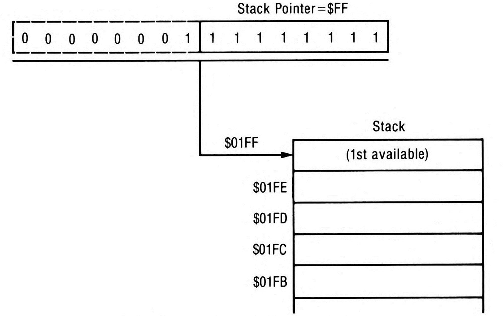
Figure 2.2. Initializing the Stack Pointer to $FF.
The push and pull instructions are one-byte instructions: the instruction itself specifies the register affected, and the value in the stack pointer register, added to $100, specifies the stack memory location to be accessed.
When a push instruction is executed, data is moved from the register specified by the instruction opcode to the stack address pointed to by the stack pointer. As Figure 2.3 shows, the value in the stack pointer is then decremented so that it points to the next lower memory location—the location to which the next push instruction encountered will store its data.
The pull instruction reverses the process and retrieves data from the stack. When a pull instruction is executed, first the stack pointer is incremented, then the register specified in the instruction opcode is loaded with the data at the incremented address pointed to by SP.
In addition to being available as a temporary storage area, the stack is also used by the system itself in processing interrupts, subroutine calls, and returns. When a subroutine is called, the current value of the program counter is pushed automatically onto the stack; the processor executes a return instruction by reloading the program counter with the value on the top of the stack.
After Pushing the Accumulator
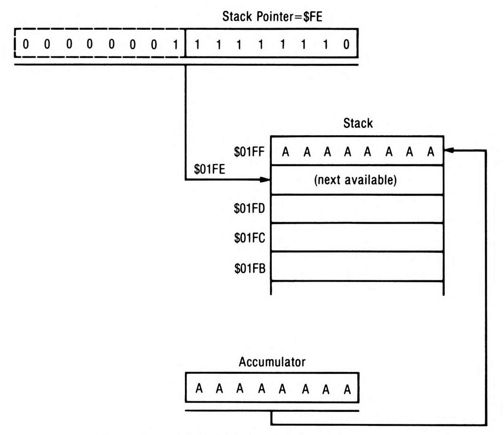
Figure 2.3. After Pushing the Accumulator.
While data is pushed into subsequently lower memory locations on the 65x's stack, the location of the last data pushed is nonetheless referred to as the top of the stack.
The Program Counter
The program counter (PC) contains the address of the next byte in the instruction stream to fetch. Execution of a program begins when the program counter is set to the program's entry point (typically the address at which it was loaded). The processor fetches an instruction opcode from that location, and proceeds to execute it. Based on the given opcode, the processor will need to fetch zero, one, or two bytes of operand from the successive locations following the instruction. When the operand has been fetched, the instruction is executed. The program counter is normally incremented to point to the next instruction in memory, except in the case of jump, branch, and call instructions, which pass control to a new location within the program by storing the new location to the program counter.
The 6502 program counter is sixteen bits wide, allowing for programs of up to 64K bytes. If the program counter is incremented past $FFFF, it wraps around to $0000.
Addressing Modes
The fourteen different addressing modes that may be used with the 6502 are shown in Table 2.3. The availability of this many different addressing modes on the 6502 gives it much of its power: Each one allows a given instruction to specify its effective address—the source of the data it will reference—in a different manner.
Table 2.3. 6502 Addressing Modes.
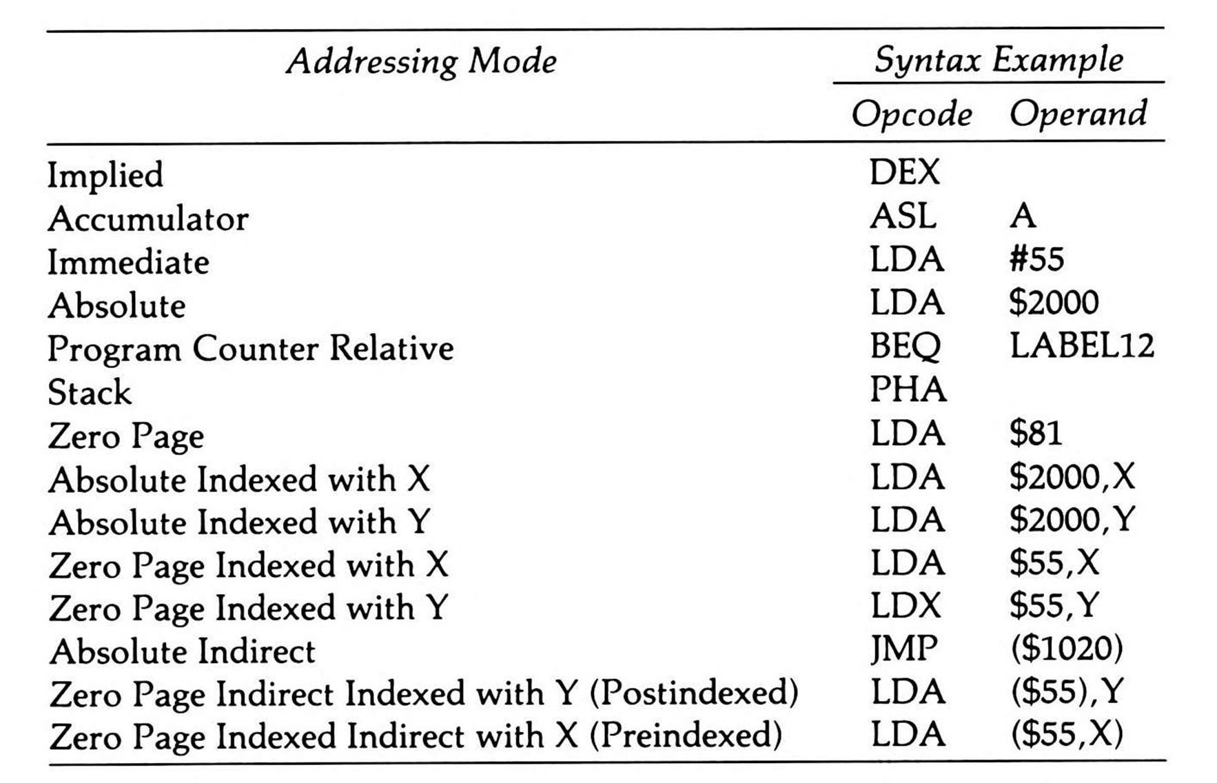
Not all addressing modes are available for all instructions; but each instruction provides a separate opcode for each of the addressing modes it supports.
For some of the 6502 addressing modes, the entire effective address is provided in the operand field of the instruction; for many of them, however, formation of the effective address involves an address calculation, that is, the addition of two or more values. The addressing mode indicates where these values are to come from and how they are to be added together to form the effective address.
Implied addressing instructions, such as DEY and INX, need no operands. The register that is the source of the data is named in the instruction mnemonic and is specified to the processor by the opcode. Accumulator addressing, in which data to be referenced is in the accumulator, is specified to the assembler by the operand A. Immediate addressing, used to access data which is constant throughout the execution of a program, causes the assembler to store the data right into the instruction stream. Relative addressing provides the means for conditional branch instructions to require only two bytes, one byte less than jump instructions take. The one-byte operand following the branch instruction is an offset from the current contents of the program counter. Stack addressing encompasses all instructions, such as push or pull instructions, which use the stack pointer register to access memory. And absolute addressing allows data in memory to be accessed by means of its address.
Like the 6800 processor, the 6502 treats the zero page of memory specially. A page of memory is an address range $100 bytes (256 decimal) long: the high bytes of the addresses in a given page are all the same, while the low bytes run from $00 through $FF. The zero page is the first page of memory, from $0000 through $00FF (the high byte of each address in the zero page is zero). Zero page addressing, a short form of absolute addressing, allows zero page operands to be referenced by just one byte, the low-order byte, resulting both in fewer code bytes and in fewer clock cycles.
While most other processors provide for some form of indexing, the 6502 provides some of the broadest indexing possibilities. Indexed effective addresses are formed from the addition of a specified base address and an index, as shown in Figure 2.4. Because the 6502's index registers (X and Y) can hold only eight bits, they are seldom used to hold index bases; rather, they are almost always used to hold the indexes themselves. The 6502's four simplest indexing modes add the contents of the X or Y register to an absolute or zero page base.
Indirection (Figure 2.5) is less commonly found in microprocessor repertoires, particularly among those microprocessors of the same design generation as the 6502. It lets the operand specify an address at which another address, the indirect address, can be found. It is at this second address that data will be referenced. The 6502 not only provides indirection for its jump instruction, allowing jumps to be vectored and revectored, but it also combines indirection with indexing to give it real power in accessing data. It's as though the storage cells for the indirect addresses are additional 6502 registers, massively extending the 6502's register set and possibilities. In one addressing mode, indexing is performed before indirection; in another, after. The first provides indexing into an array of indirect addresses and the second provides indexing into an array which is located by the indirect address.
Indexing: Base plus Index
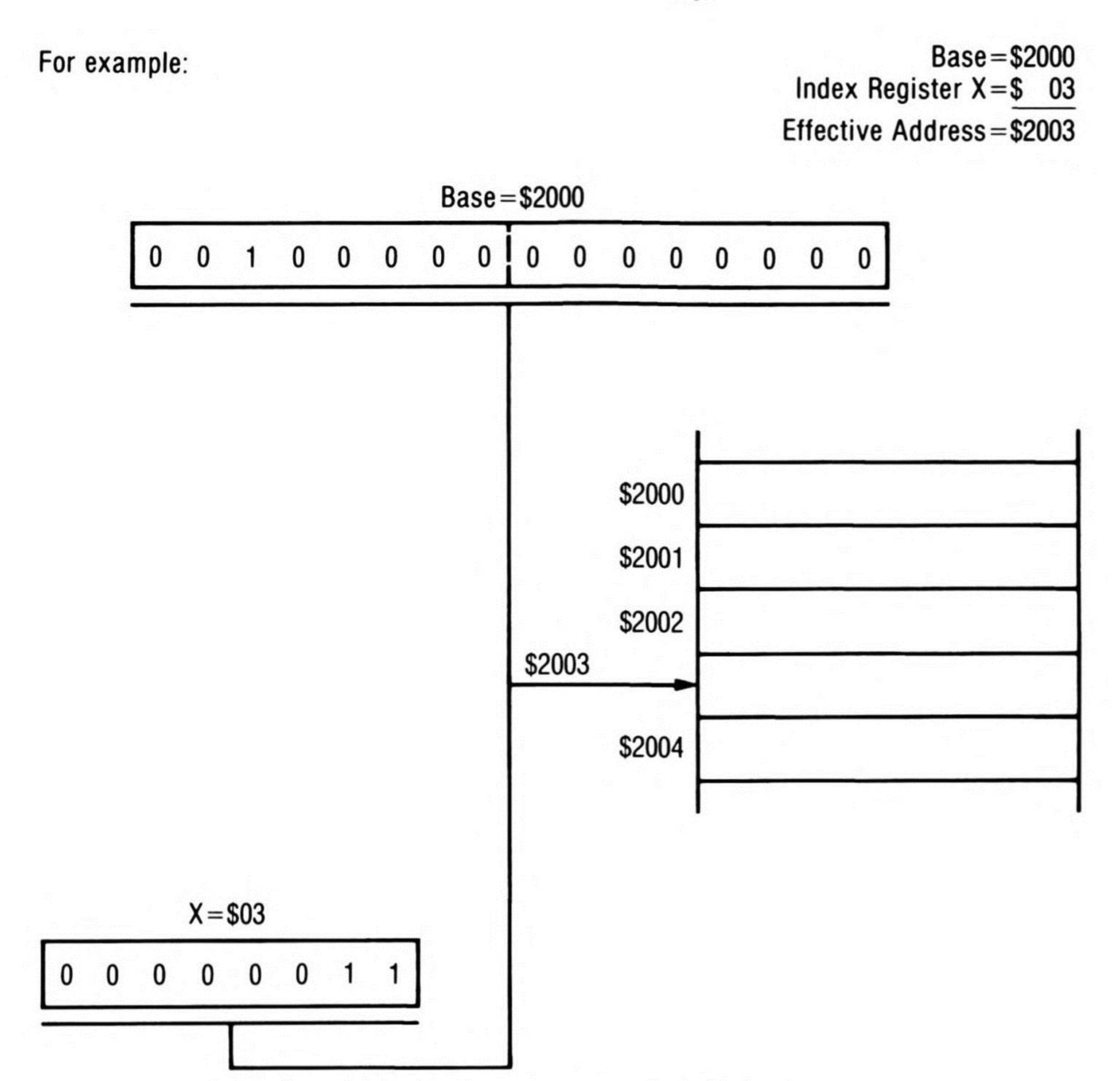
Figure 2.4. Indexing: Base Plus Index.
The full set of 65x addressing modes are explained in detail in Chapters 7 and 11 and are reviewed in the Reference Section.
Instructions
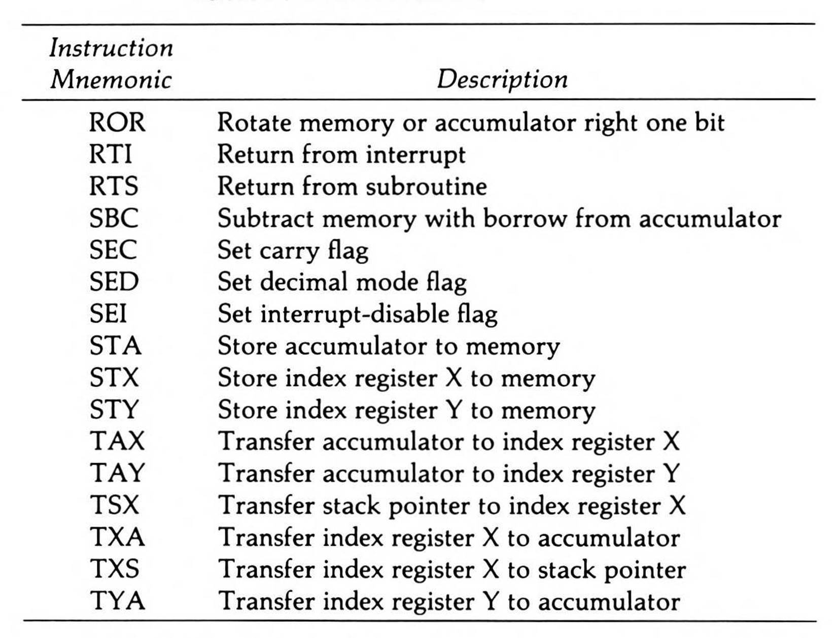
The 6502 has 56 operation mnemonics, as listed in Table 2.4, which combine with its many addressing modes to make 151 instructions available to 6502 programmers.
Indirection: Operand Locates Indirect Address
|
For example: Zero Page Operand = |
$20 |
|
Data at $20.21 (Indirect Address) = |
$3458 |
|
Effective Address = |
$3458 |
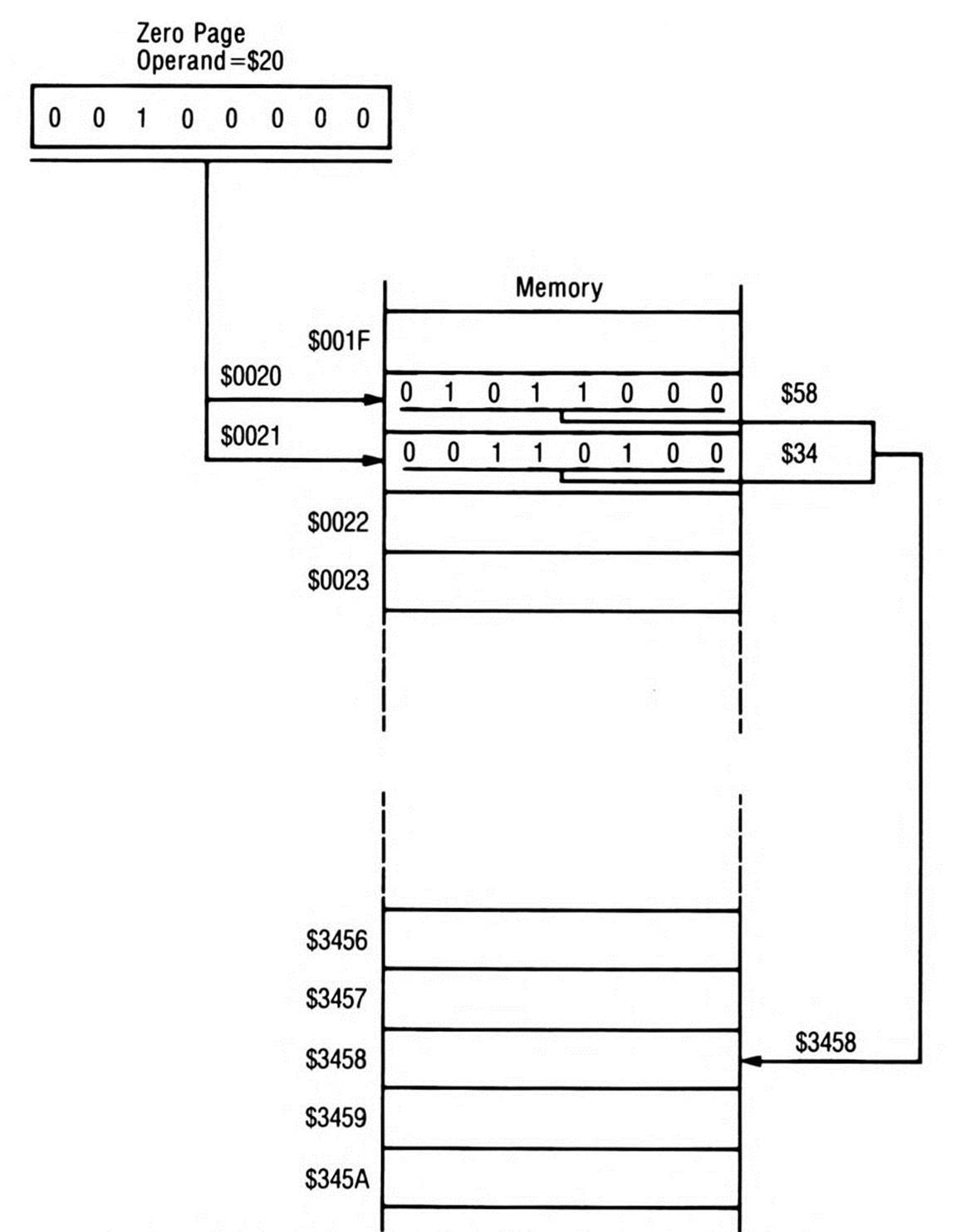
Figure 2.5. Indirection: Operand Locates Indirect Address.
Arithmetic instructions are available, including comparisons, increment, and decrement. But missing are addition or subtraction instructions which do not involve the carry; as a result, you must clear the carry before beginning an add and set it before beginning a subtraction.
Table 2.4. 6502 Instructions.
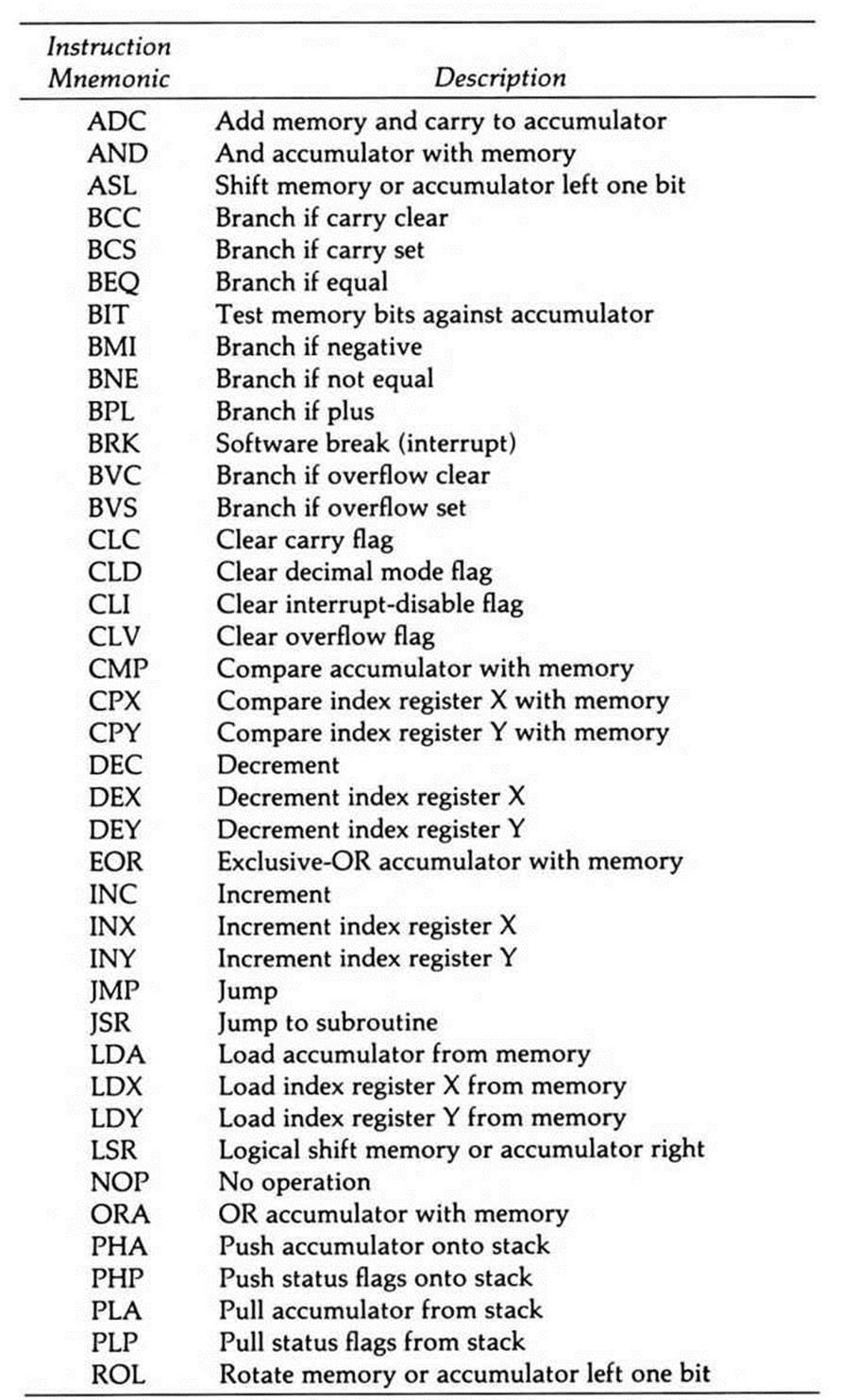
Logic instructions available include shifts and rotates, as well as an instruction for bit comparing.
Branch instructions are entirely flag-based, not arithmetic-operation based, so there are no single branch-on-greater-than, branch-on-less-than-or-equal, or signed arithmetic branches. There is also no unconditional branch and no branch-to-subroutine. The unconditional branch can be imitated by first executing one of the 6502's many clear- or set-flag instructions, then executing a branch-on-that-flag's-condition instruction.
All three of the main user registers can be loaded from and stored to memory, but only the accumulator (not the index registers) can be pushed onto and pulled from the stack (although the flags can also be pushed and pulled). On the other hand, single instructions let the accumulator value be transferred to either index register or loaded from either index register. One more transfer instruction is provided for setting the value of the stack pointer to the value in the X index register.
The 6502 System Design
There are a number of other features of the 6502's design which make it unique and make systems designed with it stand apart from systems designed with other microprocessors.
Pipelining
The 65x microprocessors have the capability of doing two things at once: the 6502 can be carrying on an internal activity (like an arithmetic or logical operation) even as it's getting the next instruction byte from the instruction stream or accessing data in memory.
A processor is driven by a clock signal which synchronizes events within the processor with memory accesses. A cycle is a basic unit of time within which a single step of an operation can be performed. The speed with which an instruction can be executed is expressed in the number of cycles required to complete it. The actual speed of execution is a function both of the number of cycles required for completion and the number of timing signals provided by the clock every second. Typical clock values for 65x processors start at one million cycles per second and go up from there.
As a result of the 6502's capability of performing two different but overlapping phases of a task within a single cycle, which is called pipelining, the 65x processors are much faster than non-pipelined processors.
Take the addition of a constant to the 6502's eight-bit accumulator as an example. This requires five distinct steps:
|
Step 1: |
Fetch the instruction opcode ADC. |
|
Step 2: |
Interpret the opcode to be ADC of a constant. |
|
Step 3: |
Fetch the operand, the constant to be added. |
|
Step 4: |
Add the constant to the accumulator contents. |
|
Step 5: |
Store the result back to the accumulator. |
Pipelining allows the 6502 to execute steps two and three in a single cycle: after getting an opcode, it increments the program counter, puts the new program address onto the address bus, and gets the next program byte, while simultaneously interpreting the opcode. The completion of steps four and five overlaps the next instruction's step one, eliminating the need for two additional cycles.
So the 6502's pipelining reduces the operation of adding a constant from five cycles to two!
The clock speed of a microprocessor has often been incorrectly presumed to be the sole determinant of its speed. What is most significant, however, is the memory cycle time. The 68000, for example, which typically operates at 6 to 12 megahertz (MHz, or millions of cycles per second) requires four clock periods to read or write data to and from memory. The 65x processors require only one clock period. Because the 6502 requires fewer machine cycles to perform the same functions, a one-megahertz 6502 has a throughput unmatched by the 8080 and Z80 processors until their clock rates are up to about four MHz.
The true measure of the relative speeds of various microprocessors can only be made by comparing how long each takes, in its own machine code, to complete the same operation.
Memory Order of Multiple-Byte Values
Multiple-byte values could be stored in memory in one of two ways: low-order byte first, followed by successively higher order bytes; or high-order byte first, followed by successively lower order bytes. The 6502, like the Intel and Zilog chips (the 8080, Z80, 8086, and so on), but unlike the Motorola chips (the 6800, 6809, 68000, and so on), puts the low-order byte first, into the lower memory address.
This seemingly unnatural order of the placement of multiple-byte values in memory can be disconcerting at first. The sixteen-bit value stored in memory as a $30 followed by $FE is not $30FE but rather $FE30. Multiple-byte values are written high-order first, to read from left to right; this is the opposite of how the bytes are placed in memory. This memory order, however, contributes to the success and speed of pipelining. Consider, as an example, the loading of the accumulator using absolute indexed addressing (two lines for a cycle indicate simultaneous operations due to pipelining):
|
Cycle 1: |
Fetch the instruction opcode, LDA. |
|
Cycle 2: |
Fetch an operand byte, the low byte of an array base. Interpret the opcode to be LDA absolute indexed. |
|
Cycle 3: |
Fetch the second operand byte, the high array base byte. Add the contents of the index register to the low byte. |
|
Cycle 4: Cycle 5: |
Add the carry from the low address add to the high byte. Fetch the byte at the new effective memory address. |
(NOTE: The 6502 also does a fetch during Cycle 4, before it checks to see if there was any carry; if there is no carry into the high byte of the address, as is often true, then the address fetched from was correct and there is no cycle five; the operation is a four-cycle operation in this case. Absolute indexed writes, however, always require five cycles.)
The low-high memory order means that the first operand byte, which the 6502 fetches before it even knows that the opcode is LDA and the addressing mode is absolute indexed, is the low byte of the address base, the byte which must be added to the index register value first; it can do that add while getting the high byte.
Consider how high-low memory order would weaken the benefits of pipelining and slow the process down:
|
Cycle 1: |
Fetch the instruction opcode, LDA. |
|
Cycle 2: |
Fetch an operand byte, the high byte of an array base. Interpret the opcode to be LDA absolute indexed. |
|
Cycle 3: |
Fetch the second operand byte, the low array base byte. Store the high byte temporarily. |
|
Cycle 4: |
Add the contents of the index register to the low byte. |
|
Cycle 5: |
Add the carry from the low address add to the high byte. |
|
Cycle 6: |
Fetch the byte at the new effective memory address. |
Memory-Mapped Input/Output
The 65x family (like Motorola's but unlike Zilog's and Intel's) accomplishes input and output not with special opcodes, but by assigning each input/output device a memory location, and by reading from or writing to that location. As a result, there's virtually no limit to the number of I/O devices which may be connected to a 65x system. The disadvantage of this method is that memory in a system is reduced by the number of locations which are set aside for I/O functions.
Interrupts
Interrupts tell the processor to stop what it is doing and to take care of some more pressing matter instead, before returning to where it left off in regular program code. An interrupt is much like a doorbell: having one means you don't have to keep going to the door every few minutes to see if someone is there; you can wait for it to ring instead.
An external device like a keyboard, for example, might cause an interrupt to present input. Or a clock might generate interrupts to toggle the processor back and forth between two or more routines, letting it do several tasks "at once." A special kind of interrupt is reset (the panic button), which is generally used out of frustration to force the processor into reinitialization. Reset generally does not return to the interrupted code after it has been served, however.
The 6502 has three interrupt vectors—memory addresses that hold the locations of routines which are automatically executed upon recognition of an interrupt by the processor. The first of these is used for reset.
The second vector is used both by maskable interrupts—those which you can force the processor to ignore, either temporarily or permanently, by setting the i interrupt bit in the status register—and by software interrupts—which are caused by the execution of the break instruction (BRK). If any hardware can cause a maskable interrupt, the interrupt service routine pointed to by this vector must determine the source of the interrupt. It must poll a status flag on each possible hardware source as well as check the stacked status register's b flag, which is set and pushed when a break instruction is executed. When it finds the source of the interrupt, it must then branch to a routine which will respond to the interrupt in a way appropriate to the source (getting a character from a communications port, for example).
The third vector is used by nonmaskable interrupts, those which interrupt regardless of the i bit in the status register. The non-maskable interrupt is usually reserved for a single high-priority or time-critical interrupt, such as refresh of a CRT screen or to warn of impending power failure.
The 6502 was designed to service interrupts as fast as possible. Because interrupts cannot be served until the current instruction is completed (so no data is lost), the worst case is the longest instruction time and the 6502's instructions each take very few cycles to execute. As a result, the 6502 and its successors have the lowest interrupt latency—the time between interrupt occurrence and interrupt-handling response—of any eight-bit or sixteen-bit processors.
NMOS Process
The 6502 is fabricated using the NMOS (pronounced "EN moss") process (for N-channel Metal-Oxide Semiconductor). Still one of the most common of the technologies used in large-scale and very-large-scale integrated circuits, NMOS was, at the time the 6502 was designed and for many years after, the most cost-efficient of the MOS technologies and the easiest process for implementation of relatively high-speed parts. This made NMOS popular among designers of microcomputers and other devices in which hardware cost was an important design factor.
Most of the current generation of 8-, 16-, and 32-bit processors were originally implemented in NMOS. Some, like the 6502, are still only available in NMOS process versions. Others, like all of the recently designed members of the 65x family (the 65C02, 65802, and 65816) were produced exclusively using the CMOS process.
Bugs and Quirks
The 6502 has a number of features which the less enthusiastic might be inclined to call bugs or quirks.
The one most clearly a bug involves using indirect addressing with the jump instruction, when its operand ends in $FF. To use an example, should cause the program counter to get, as its new low byte, the contents of $20FF, and as its new high byte, the contents of $2100. However, while the 6502 increments the low byte of the indirect address from $FF to 00, it fails to add the carry into the high byte, and as a result gets the program counter's new high byte from $2000 rather than $2100.
|
JMP |
($20FF) |
You can also run into trouble trying to execute an unused opcode, of which the 6502 has many. The results are unpredictable, but can include causing the processor to "hang."
Finally, the decimal mode is not as easy to use as it might be. The negative, overflow, and zero flags in the status register are not valid in decimal mode and the setting of the decimal flag, which toggles the processor between binary and decimal math, is unknown after the processor has received a hardware "reset".
All materials on the site are licensed Creative Commons Attribution-Sharealike 3.0 Unported CC BY-SA 3.0 & GNU Free Documentation License (GFDL)
If you are the copyright holder of any material contained on our site and intend to remove it, please contact our site administrator for approval.
© 2016-2026 All site design rights belong to S.Y.A.