Programming the 65816 Including the 6502, 65C02, and 65802 (1986)
Part II. Architecture
4. Sixteen-Bit Architecture: The 65816 and the 65802
While the 65C02 was designed more as a CMOS replacement for the 6502 than an enhancement of it, the 65802 and 65816 were created to move the earlier designs into the world of sixteen-bit processing. And although the eight-bit 6502 had been a speed demon when first released, its competition changed over the years as processing sixteen bits at a time became common, and as the memory new processors could address started at a megabyte.
The 65816 and the 65802 were designed to bring the 65x family into line with the current generation of advanced processors. First produced in prototypes in the second half of 1984, they were released simultaneously early in 1985. The 65816 is a full-featured realization of the 65x concept as a sixteen-bit machine. The 65802 is its little brother, with the 65816's sixteen-bit processing packaged with the 6502's pinout for compatibility with existing hardware.
The two processors are quite similar. They are, in fact, two different versions of the same basic design. In the early stages of the chip fabrication process they are identical and only assume their distinct "personalities" during the final (metalization) phase of manufacture.
The two processors provide a wealth of enhancements: another nine addressing modes, 78 new opcodes, a "hidden" second accumulator in eight-bit mode, and a zero page which, renamed the direct page, can be relocated to any contiguous set of $100 bytes anywhere within the first 64K of memory (which in the case of the 65802 is anywhere in its address space). The most dramatic of all the enhancements common to both 65802 and 65816, though, is the expansion of the primary user registers—the accumulator, index registers, and stack pointer—to sixteen-bit word size. The accumulator and index registers can be toggled to sixteen bits from eight, and back to eight when needed. The stack, pointed to by an expanded-to-sixteen-bit stack register, can be relocated from page one to anywhere in a 64K range.
The primary distinction between the two processors is the range of addressable memory: the 65816 can address up to sixteen megabytes; the 65802 is constrained by its 6502 pinout to 64K.
A secondary distinction between the two processors is that the 65816's new pinout also provides several significant new signals for the hardware designer. While outside the primary scope of this book, these new signals are mentioned in part in this chapter and described in some detail in Appendix C.
It is important to remember that the 65802 is in fact a 65816 that has been coerced to live in the environment designed originally for the 6502 and 65C02. Outside of the memory and signal distinctions just listed, the 65816 and the 65802 are identical. Both have a native mode, in which their registers can be used for either eight- or sixteen-bit operations. Both have a 6502 emulation mode, in which the 6502's register set and instruction timings emulate the eight-bit 6502 (not the 65C02) exactly (except they correct a few 6502 bugs). All existing 6502 software can be run by the new processor—as can virtually all 65C02 software—even as most of the native mode's enhancements (other than sixteen-bit registers) are programmable in emulation mode, too.
To access sixteen megabytes, the signals assigned to the various pins of the 65816's 40-pin package are different from the 6502, the 65C02 and the 65802, so it cannot be installed in existing 65x computers as a replacement upgrade. The 65802, on the other hand, has a pinout that is identical to that of the 6502 and 65C02 and can indeed be used as a replacement upgrade.
This makes the 65802 a unique, pin-compatible, software-compatible sixteen-bit upgrade chip. You can pull a 6502 out of its socket in any existing 6502 system, and replace it with a 65802 because it powers-on in the 6502 emulation mode. It will run existing applications exactly the same as the 6502 did. Yet new software can be written, and 6502 programs rewritten, to take advantage of the 65802's sixteen-bit capabilities, resulting in programs which take up much less code space and which run faster. Unfortunately, even with a 65802 installed, an older system will remain unable to address memory beyond the original 64K limits of the 6502. This is the price of hardware compatibility.
The information presented in this chapter builds directly on the information in the previous two chapters; it should be considered as a continuous treatment of a single theme. Even in native mode with sixteen-bit registers, the 65802 and 65816 processors utilize many of the 6502 and 65C02 instructions, registers, and addressing modes in a manner which differs little from their use on the earlier processors. If you are already familiar with the 6502 or the 65C02, you will discover that the 65802 and 65816 logically expand on these earlier designs.
Power-On Status: 6502 Emulation Mode
When the 65816 and 65802 are powered on, they initialize themselves into 6502 emulation mode in which, with the exception of fixing several 6502 bugs, they exactly emulate the 6502. The stack is confined to page one, just like the 6502 stack pointer. The registers are configured to eight bits, to model the 6502's registers. Every 6502 instruction is implemented identically. The timing of each instruction is exactly the same as on the original NMOS 6502. The direct page of the 65802 and 65816, which as you will learn can be relocated using the sixteen-bit direct page register, is initialized to page zero, making direct page addressing exactly equivalent to 6502 zero page addressing. The program and data bank registers, which as you will learn provide efficient access in the 65816 to any one or two 64K banks of memory at a time, are initialized to the zero bank.
Unlike the NMOS 6502, which has undefined results when unimplemented opcodes are executed, and the 65C02, which treats unimplemented opcodes as variously-timed and -sized no-operations, the 65802 instruction set implements every one of the 256 possible one-byte opcodes. These additional instructions are available in emulation mode as well as in native mode.
Among the newly implemented opcodes are ones that allow the processors to be switched to their native mode—sixteen-bit operation. While there is more to say about 6502 emulation mode, it will be easier to understand in the context of native mode.
The Full-Featured 65x Processor: The 65816 in Native Mode
The 65816 in its native mode (as opposed to its 6502 emulation mode) has it all: sixteen-bit registers, 24-bit addressing, and all the rest. The 65802's native mode is a subset of this, as are the emulation modes of both processors.
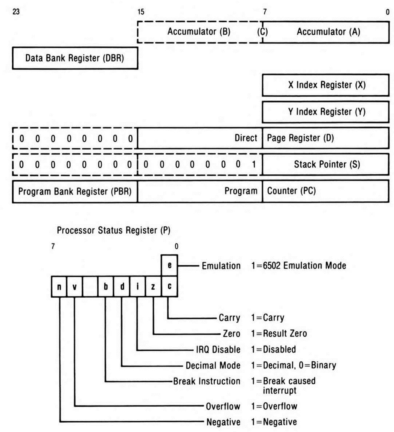
Figure 4.1 shows the programming model for the 65816 in native mode. While the accumulator is shown as a sixteen-bit register, it may be set to be either a single sixteen-bit accumulator (A or C) or two eight-bit accumulators, one accessible (A) and the other hidden but exchangeable (B). While the index registers are shown as sixteen-bit registers, they may be set, as a pair, to be either sixteen-bit registers or eight-bit registers—their high bytes are zeroed when they are set to eight bits. The obvious advantage of switching from a processor with eight-bit registers to one with sixteen-bit registers is the ability to write programs which are from 25 to 50 percent shorter, and which run 25 to 50 percent faster due to the ease with which sixteen-bit data is manipulated.
The feature that most clearly distinguishes the current generation of advanced microcomputer systems, however, is the ability to address lots of memory. It is this increased memory addressability which has ushered in the new era of microcomputer applications possibilities, such as large spreadsheets, integrated software, multi-user systems, and more. In this regard, the 65816 stands on or above par with any of the other high-performance microprocessors, such as the 68000, the 8086, or their successors.
65816 Native Mode Programming Model
(16-bit accumulator & index register modes: m=0 & x=0)
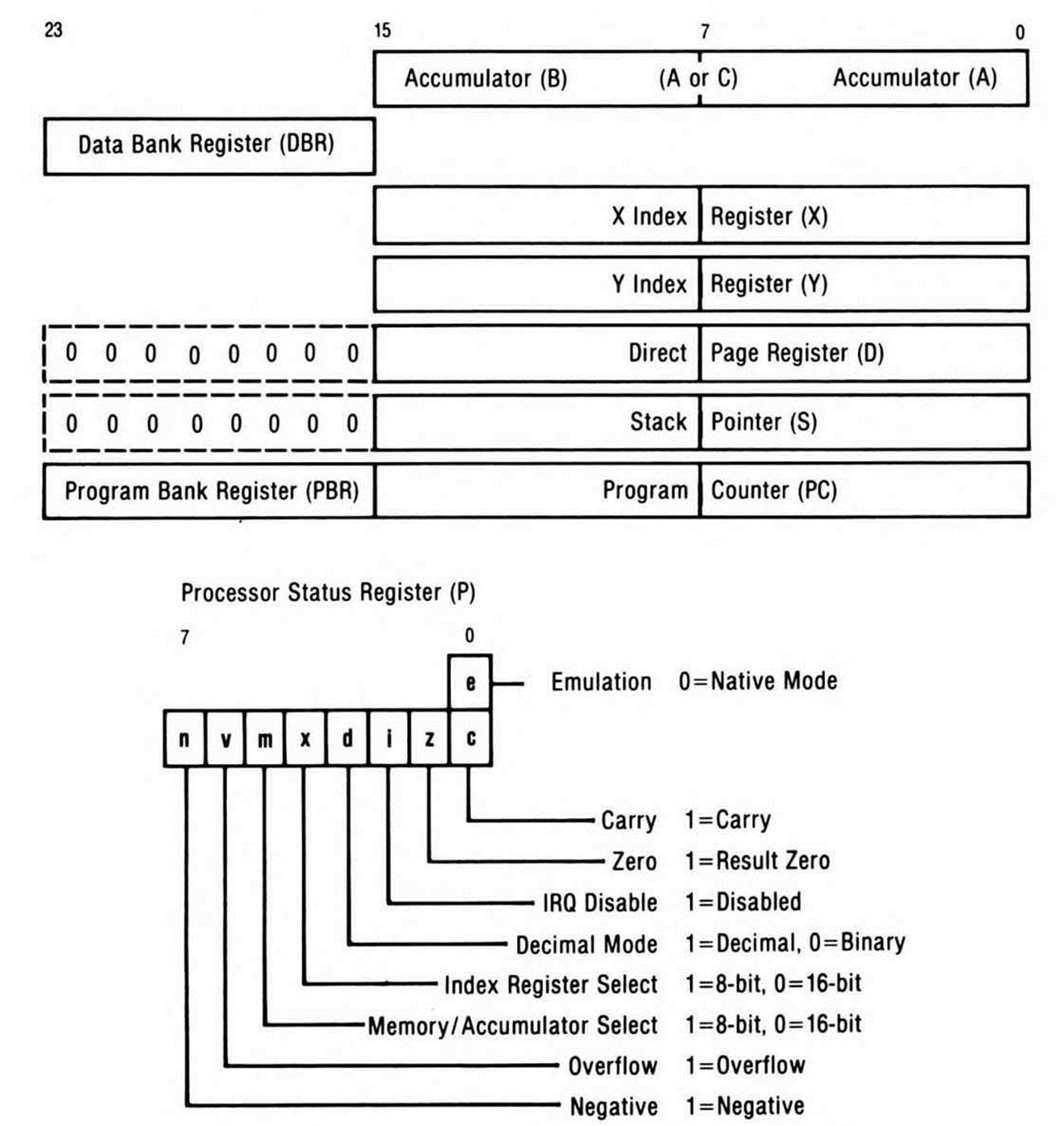
Figure 4.1. 65816 Native Mode Programming Model.
There are two new eight-bit registers called bank registers. One, called the data bank register, is shown placed above the index registers and the other, called the program bank register, is appended to the program counter. The 65816 uses the two bank registers to provide 24-bit addressing.
A bank of memory is much like a page; just as a page is a range of memory that can be defined by eight bits (256 bytes), a bank is a range of memory that can be defined by sixteen bits (64K bytes). For processors like the 6502, which have only sixteen-bit addressing, a 64K bank is not a relevant concept, since the only bank is the one being currently addressed. The 65816, on the other hand, partitions its memory range into 64K banks so that sixteen-bit registers and addressing modes can be used to address the entire range of memory.
Bank zero, for example, is that 64K range for which, when addressed using 24 bits, the highest byte (also called the bank byte) is zero. Similarly, a highest byte of nine in a 24-bit address would address a location somewhere in bank nine. This highest byte is called the bank byte so that the term high byte can still be used to refer to the byte that determines the page address. In other words, "high byte" is used on the 65816 as it is on the 6502, 65C02 and 65802, where addresses are only sixteen bits.
Another new register shown in Figure 4.1 is the direct page register. Much like the 6800's special zero page became the 6809's direct page, the 6502's and 65C02's zero page has been transformed into the 65802's and 65816's direct page. This direct page is, as Figure 4.1shows, limited to bank zero, shown in the programming model by the implied zero as its bank byte. The direct page register can be set to any 256-byte page starting on any byte boundary within bank zero. All of the 6502 instructions that use zero page addressing use an expanded form called direct page addressing on the 65816 and 65802; however, when the direct page register value is zero, the two modes are operationally identical.
Figure 4.1 also shows that the stack pointer has been unbound from page one to float anywhere in bank zero by making it a sixteen-bit register.
While Figure 4.1 doesn't show the interrupt vectors, they too are located in bank zero, and they point to interrupt handling routines which also must be located in bank zero.
Finally, the status register is different from the 6502's and 65C02's (compare Figure 4.1 with Figure 2.1 in Chapter 2). The first obvious difference is the single bit labelled e for emulation hanging off the top of the carry flag. Accessible only through the carry flag, its contents determine whether the processor is in native or 6502 emulation mode. Here it holds a zero to indicate the processor is in native mode. The second difference is the m and x flags replace the 6502's break and unused flags: m indicates the size of the accumulator (eight or sixteen bits) as well as the size of memory accesses; x indicates the size of the two index registers (eight or sixteen bits). Changing the contents of either of these two new flags toggles the size of the corresponding registers. The b flag is no longer necessary to distinguish the BRK software interrupt from hardware interrupts because native mode provides a new interrupt vector for software interrupts, separate from the hardware interrupt vector.
Native mode also provides one timing improvement over the 6502: one cycle is saved during a cross-page branch.
The Program Bank Register
The 65816's sixteen-bit program counter is concatenated to its eight-bit program counter bank register (PBR, or K when used in instruction mnemonics) to extend its instruction-addressing capability to 24 bits. When the 65816 gets an instruction from memory, it gets it from the location pointed to by the concatenation of the two registers. In many ways, the net effect is a 24-bit program counter; for example, when an interrupt occurs, all 24 bits (program counter plus program counter bank) are pushed onto the stack. Likewise, when a return-from-interrupt occurs, 24 bits (both registers) are pulled from the stack.
All previous instructions that jumped to sixteen-bit absolute addresses still work by staying within the same bank. Relative branches stay in the same bank; that is, you can't branch across bank boundaries. And program segments cannot cross bank boundaries; if the program counter increments past $FFFF, it rolls over to $0000 without incrementing the program counter bank.
New instructions and addressing modes were added to let you transfer control between banks: jump absolute long (jump to a specified 24-bit address), jump indirect long (the operand is an absolute address in bank zero pointing to a 24-bit address to which control is transferred), jump to subroutine long (to a specified 24-bit address, with the current program counter and program bank register pushed onto the stack first), and a corresponding return from subroutine long, which re-loads the bank register as well as the program counter. (The addressing modes are among those listed in Table 4.3, the instructions in Table 4.4.)
These instructions that specify a complete 24-bit address to go to, along with native mode's software interrupt and return from interrupt instructions, are the only ones that modify the value in the program bank register. The program bank can be pushed onto the stack so it can be pulled into another register and be examined or tested. But there is no instruction for pulling the program bank register from the stack, since that would change the bank the next instruction would come from—certain to be catastrophic. To avoid such "strange" branches across banks, the program counter bank register can only be changed when the program counter is changed at the same time.
The Data Bank Register
The data bank register (DBR or, when used as part of a mnemonic, B) defines the default bank to be used for reading or writing data whenever one of the addressing modes that specifies (only) a sixteen-bit address is used, such as the absolute, indirect, or indexed instructions found on the 6502. Such sixteen-bit effective addresses as used with the 6502 are concatenated with the value in the data bank register to form a 24-bit address, much as the program counter is concatenated with the program bank register. An important difference is that, unlike the program counter bank register, the data bank register can be temporarily incremented by instructions which use indexed addressing; in other words, bank boundaries do not confine indexing, which crosses them into the next bank.
As already mentioned, direct page and stack-based values are always accessed in bank zero, since the implied bank used with the direct page and stack is zero. But indirect addresses pulled out of the direct page or off the stack (when used with addressing modes that do not further specify the bank value) point to locations in the current data bank.
The existence of the data bank register on the 65816 provides a convenient way to access a large range of data memory without having to resort to 24-bit address operands for every operation.
The Direct Page Register
The direct page register (D) points to the beginning of direct page memory, which replaces zero page memory as the special page used for short-operand addressing. All of the 6502 instructions that use zero page addressing use an expanded form called direct page addressing on the 65816 and 65802. If the direct page register is set to zero, then direct page memory is the zero page, and direct page addressing is operationally identical to zero page addressing.
One effect of having a direct page register is that you can set up and alternate between multiple direct page areas, giving each subroutine or task its own private direct page of memory, which can prove both useful and efficient.
The Stack Pointer
The native mode stack pointer holds a sixteen-bit address value. This means it can be set to point to any location in bank zero. It also means the stack is no longer limited in length to just $100 bytes, nor limited to page one ($100 to $1FF). Page one therefore loses its character as a "special" memory area and may be treated like any other page while running the 65802 or 65816 in the native mode.
The Accumulator and the Index Registers
The key difference between the 65816/65802 and the earlier processors in the series is that the 65816's three primary user registers—the accumulator and the X and Y index registers—can be toggled between eight and sixteen bits. You can select which size (eight or sixteen bits) you wish to use by executing special control instructions that modify the new m and x flags.
This enhances the basic processing power of the chip tremendously. A simple subtraction of sixteen-bit numbers, for example, illustrates the difference. The eight-bit 6502 must be programmed to load the low byte of the first sixteen-bit number, subtract the low byte of the second number, then save the result, load the first number's high byte, subtract the second number's, and finally, save the high result. The sixteen-bit processors, on the other hand, can load one sixteen-bit value, subtract the other, then save the sixteen-bit result. Three steps replace six.
With its ability to change register size, the 65816 functions equally well with eight bits or sixteen. From the programmer's point of view, it is a dual word-size machine. The machine word size—the basic unit of data the machine processes in a given instruction cycle—may be either byte or double byte, that is, eight or sixteen bits.
In the terminology used in describing other sixteen-bit processors, the term word is used specifically to refer to sixteen-bit data, and byte to refer to eight-bit data. But other sixteen-bit processors generally have different mechanisms for selecting byte or double byte data to operate upon. The terminology appropriate to the 65802 and 65816 is to refer to sixteen-bit data as double byte, rather than word, since their word size alternates between eight bits and sixteen, and since they can operate in either byte mode or double byte mode with equal effectiveness. They are hybrid processors.
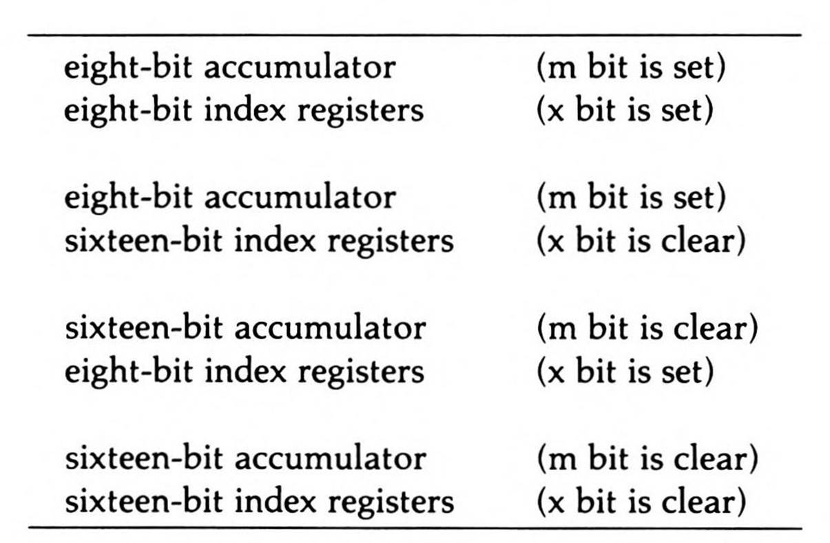
The width of the accumulator and the width of the index registers are independently controlled by setting and resetting the two special flag bits within the status register, the index register select (x) and memory/accumulator select (m) flags. When both are set, the eight-bit register architecture of the 6502 is in force. While very similar to the emulation mode, this eight-bit native mode is subtly different in important ways: a BRK vector is available in the native mode; interrupt processing is different between emulation and native mode in general; and of course sixteen-bit processing can be called up with a single instruction. Yet the 65802 and 65816 will execute a good deal of existing 6502 programs without modification in this mode.
When either or both the index register select or memory select flags are cleared, the word size of the corresponding register(s) is expanded from eight bits to sixteen.
The four possible modes of operation are shown in Table 4.1.
Table 4.1. The Four Possible Native Mode Register
Combinations.
When the opcode for a given instruction is fetched from memory during program execution, the processor may respond differently based upon the settings of the two register select flags. Their settings may be thought of as extensions to the opcode. For example, consider the following instruction:
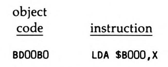
which loads the accumulator with data from the effective address formed by the sum of $B000 and the contents of the X register. The X register contents can be either eight bits or sixteen, depending upon the value of the index select flag. Furthermore, the accumulator will be loaded from the effective address with either eight or sixteen bits of data, depending upon the value of the memory/accumulator select flag.
The instruction and addressing mode used in the example are found also on the 6502 and 65C02; the opcode byte ($BD) is identical on all four processors. The 65816's new mode flags greatly expand the scope of the 6502's instructions. For programmers already familiar with the 6502, the understanding of this basic principle—how one opcode can have up to four different effects based on the flag settings—is the single most important principle to grasp in moving to a quick mastery of the 65802 or 65816.
Switching Registers Between Eight and Sixteen Bits
The two register select flags are set or cleared by two new instructions provided for modifying the status register: one of the instructions, SEP, (set P) can be used to set any bit or bits in the P status register; the other, REP, (reset P) can be used to reset any bit or bits in the status register.
Figure 4.2 shows the results of changing the index registers and accumulator between eight and sixteen bits. When a sixteen-bit index register is switched to eight bits, the high byte is lost irretrievably and replaced by a zero. On the other hand, when an eight-bit index register is switched to sixteen bits, its unsigned value is retained by concatenating it to a zero high byte; that is, the eight-bit unsigned index already in the register is extended to sixteen bits.
Unlike the index operations, switching the accumulator's size in either direction is reversible. The accumulator is treated differently due to its function, not as an index register, but as the register of arithmetic and logic. In this role, it is often called upon to operate on eight-bit values with sixteen-bit ones and vice versa.
When the sixteen-bit A accumulator is switched to eight bits, the low byte becomes the new eight-bit A accumulator while the high byte becomes the eight-bit "hidden" B accumulator. B may be seen as an annex to the A accumulator, accessible only through a new instruction which exchanges the values in the two accumulators (making B useful for temporarily storing off the eight-bit value in A). Conversely, when the accumulator is switched from eight bits to sixteen, the new sixteen-bit A accumulator has, as its low byte, the previous eight-bit A accumulator and, as its high byte, the previous hidden B accumulator.
Certain instructions that transfer the accumulator to or from other sixteen-bit registers refer to the sixteen-bit accumulator as C to emphasize that all sixteen accumulator bits will be referenced regardless of whether the accumulator is set to eight- or sixteen-bit mode. Again, this is illustrated in Figure 4.2.
The Status Register
Because the emulation bit is a "phantom" bit, it cannot be directly tested, set, or cleared. The flag that it "phantoms" or overlays is the carry bit; there is a special instruction, XCE, that exchanges the contents of the two flags. This is the "trapdoor" through which the emulation mode is entered and exited.
Two status register bits were required for the two-flag eight-or-sixteen-bit scheme. While the 6502's status register has only one unused status register bit available, its break flag is used only for interrupt processing, not during regular program execution, to flag whether an interrupt comes from a break instruction or from a hardware interrupt. By giving the break instruction its own interrupt vector in native mode, the 65816's designers made a second bit available for the m and x register select flags.
Results of Switching Register Sizes
(L = bits in low byte; H = bits in high byte)
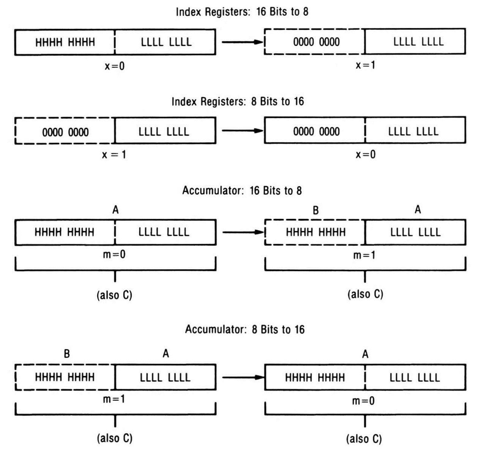
Figure 4.2. Results of Switching Register Sizes.
6502/65C02 Addressing Modes on the 65816
All of the 6502 and 65C02 addressing modes are available to the 65816/65802, but native mode's sixteen-bit features mean you need to expand your thinking about what they will do. For example, the 65816's direct page, which can be located anywhere in memory, replaces the earlier zero page as the special page for short-operand addressing modes. All 6502/65C02 zero page addressing modes become direct page addressing modes, as shown in Table 4.2.
Table 4.2. Addressing Modes: Zero Page vs. Direct Page.
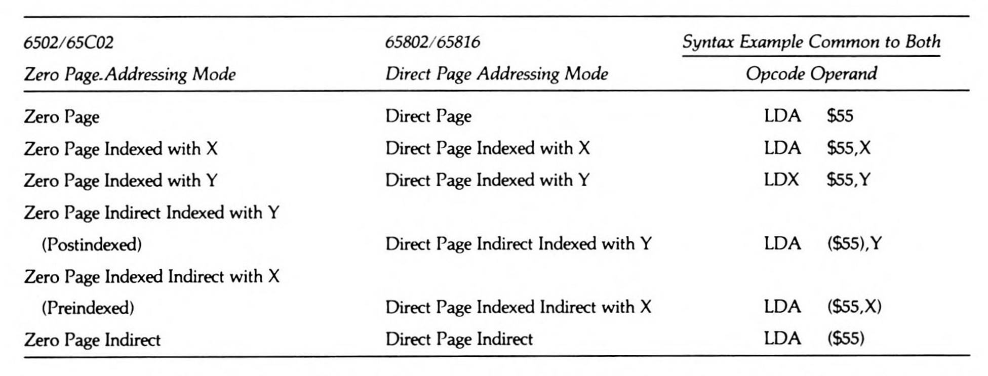
Notice in Table 4.2 that the assembler syntax for each direct page addressing mode (not to mention the object bytes themselves) is the same as its zero page counterpart. The names and the results of the addressing modes are what differ. Direct page addressing, like the 6502/65C02 zero page addressing, allows a memory location to be addressed using only an eight-bit operand. In the case of the 6502, a sixteen-bit zero page effective address is formed from an eight-bit offset by concatenating a zero high byte to it. In the 65802/65816, the direct page effective address is formed by adding the eight-bit offset to the sixteen-bit value in the direct page register. This lets you relocate the direct page anywhere in bank zero, on any byte boundary. Note, however, that it is most efficient to start the direct page on a page boundary because this saves one cycle for every direct page addressing operation.
When considering the use of 6502/65C02 zero page instructions as 65802/65816 direct page instructions, remember that a direct page address of $23 is located in memory at location $0023 only if the direct page register is set to zero; if the direct page register holds $4600, for example, then direct page address $23 is located at $4623. The direct page is essentially an array which, when it was the zero page, began at address zero, but which on the 65816 and 65802 can be set to begin at any location.
In the 6502/65C02, the effective address formed using zero page indexed addressing from a zero page base address of $F0 and an index of $20 is $10; that is, zero page indexed effective addresses wrap around to always remain in the zero page. In the emulation mode this is also true. But in native mode, there is no page wraparound: a direct page starting at $2000 combined with a direct page base of $20 and a sixteen-bit index holding $300 results in an effective address of $2320.
The three main registers of the 65802/65816 can, in native mode, be set to hold sixteen bits. When a register is set to sixteen bits, then the data to be accessed by that register will also be sixteen bits.
For example, shifting the accumulator left one bit, an instruction which uses the accumulator addressing mode, shifts sixteen bits left rather than eight if the accumulator is in sixteen-bit mode. Loading a sixteen-bit index register with a constant using immediate addressing means that a sixteen-bit value follows the instruction opcode. Loading a sixteen-bit accumulator by using absolute addressing means that the sixteen-bit value stored starting at the absolute address, and continuing into the location at the next address, is loaded into the accumulator.
Sixteen-bit index registers give new power to the indexed addressing modes. Sixteen-bit index registers can hold values ranging up to 64K; no longer must the double-byte base of an array be specified as a constant with the index register used for the index. A sixteen-bit index can hold the array base with the double-byte constant specifying the (fixed) index.
Finally, the 65816 has expanded the scope of 6502 and 65C02 instructions by mixing and matching many of them with more of the 6502/65C02 addressing modes. For example, the jump-to-subroutine instruction can now perform absolute indexed indirect addressing, a mode introduced on the 65C02 solely for the jump instruction.
New 65816 Addressing Modes
Not only do the 65802 and 65816 provide all the 6502 and 65C02 addressing modes, but they also offer nine new addressing modes of their own, in both emulation and native modes. They are shown in Table 4.3.
Table 4.3. The 65816/65802’s New Addressing Modes.
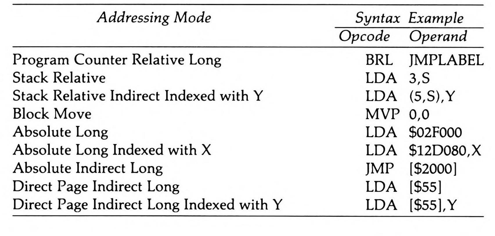
There are six new addressing modes that use the word "long", but with two very different meanings. Five of the "long" modes provide 24-bit addressing for interbank accesses. Program counter relative long addressing, on the other hand, provides an intrabank sixteen-bit form of relative addressing for branching. Like all the other branch instructions, its operand is an offset from the current contents of the program counter, but branch long's operand is sixteen bits instead of eight, which expands relative branching from plus 127 or minus 128 bytes to plus 32767 or minus 32768. This and other features greatly ease the task of writing position-independent code. The use of the word "long" in the description of this addressing mode means "longer than an eight bit offset," whereas the word "long" used with the other four addressing modes means "longer than sixteen bits."
Stack relative addressing and Stack relative indirect indexed with Y addressing treat the stack like an array and index into it. The stack pointer register holds the base of the array, while a one-byte operand provides the index into it. Since the stack register points to the next available location for data, a zero index is meaningless: data and addresses which have been pushed onto the stack start at index one. For stack relative, this locates the data; for stack relative indirect indexed, this locates an indirect address that points to the base of an array located elsewhere. Both give you the means to pass parameters on the stack in a clean, efficient manner. Stack relative addressing is a particularly useful capability, for example, in generating code for recursive high-level languages such as Pascal or C, which store local variables and parameters on a "stack frame."
Block move addressing is the power behind two new instructions that move a block of bytes—up to 64K of them—from one memory location to another all at once. The parameters of the move are held in the accumulator (the count), the index registers (the source and destination addresses), and a unique double operand (the source and destination addresses in the operand specify the source and destination banks for the move operation).
The five remaining "long" addressing modes provide an alternative to the use of bank registers for referencing the 65816's sixteen-megabyte address space. They let you temporarily override the data bank register value to address memory anywhere within the sixteen-megabyte address space. Absolute long addressing, for example, is just like absolute addressing except that, instead of providing a two-byte absolute address to be accessed in the data bank, you provide a three-byte absolute address which overrides the data bank. Absolute long indexed with X, too, is four bytes instead of three. On the other hand, it is the memory locations specified by absolute indirect long, direct page indirect long, and direct page indirect long indexed with Y that hold three-byte indirect addresses instead of two-byte ones. Three-byte addresses in memory appear in conventional 65x order; that is, the low byte is in the lower memory location, the middle byte (still referred to in 6502 fashion as the "high" byte) is in the next higher location, and the highest (bank) byte is in the highest location.
Instructions
There are 78 new opcodes put into use through the 28 new operations listed in Table 4.4, as well as through giving the previous processors' operations additional addressing modes.
Table 4.4. New 65816/65802 Instructions.
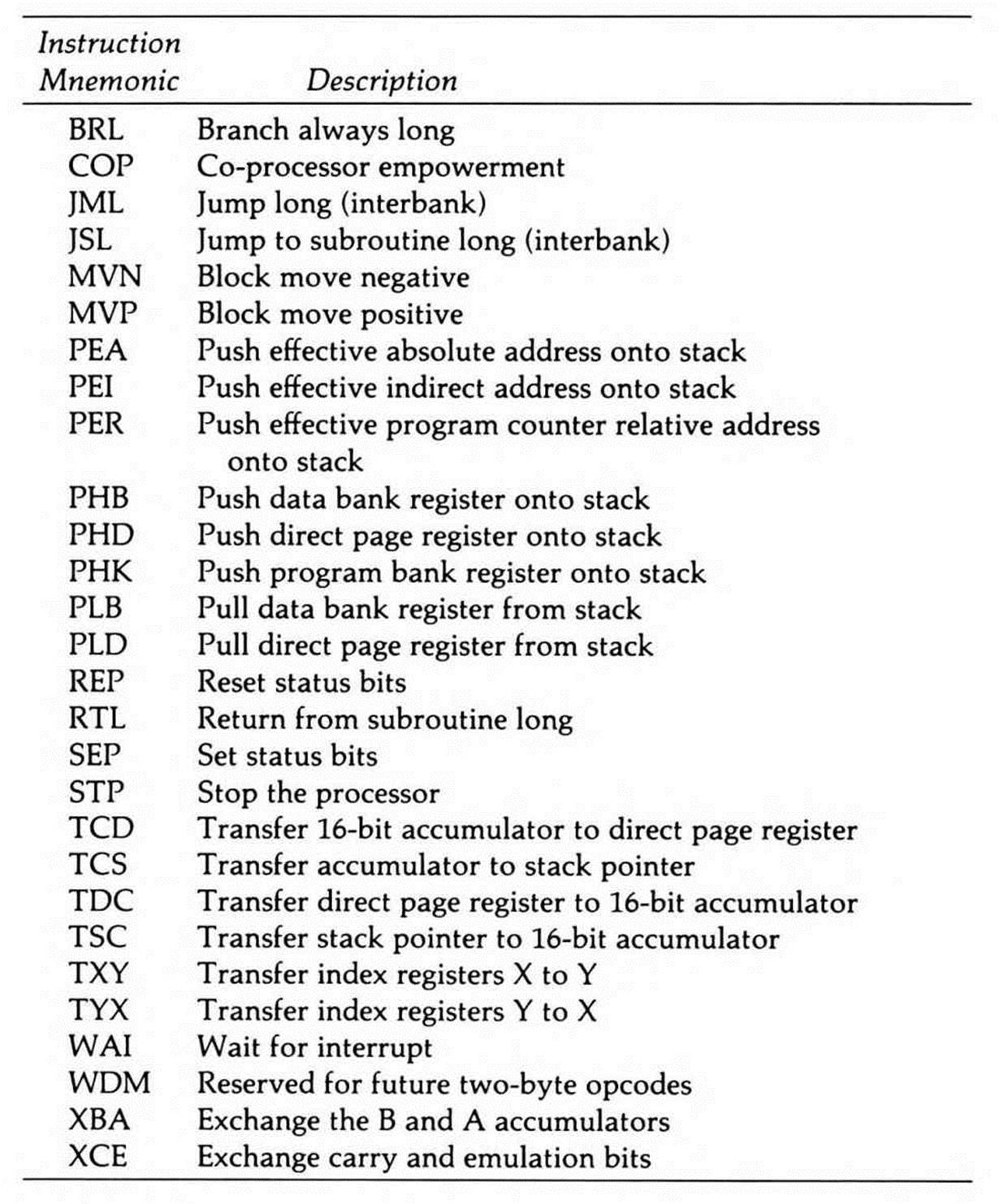
Five of the new push and pull instructions allow the new registers to be stored on the stack; the other three let you push constants and memory values onto the stack without having to first load them into a register. PER is unique in that it lets data be accessed relative to the program counter, a function useful when writing relocatable code.
There are also instructions to transfer data between new combinations of the registers, including between the index registers—a long-wished-for operation; to exchange the two bytes of the sixteen-bit accumulator; and to exchange the carry and emulation bits, the only method for toggling the processor between emulation and native modes.
There are new jump, branch, return, and move instructions already described in the section on addressing modes. There's a new software interrupt provided for sharing a system with a co-processor. There are two instructions for putting the processor to "sleep" in special low-power states. And finally, there's a reserved opcode, called WDM (the initials of the 65816's designer, William D. Mensch, Jr.), reserved for some future compatible processor as the first byte of a possible 256 two-byte opcodes.
Interrupts
Native mode supplies an entire set of interrupt vectors at different locations from the emulation mode (and earlier 6502/65C02) ones to service native mode and emulation mode interrupts differently. Shown in Table 4.5, all are in bank zero; in addition, the sixteen-bit contents of each vector points to a handling routine which must be located in bank zero.
Table 4.5. Interrupt Vector Locations.
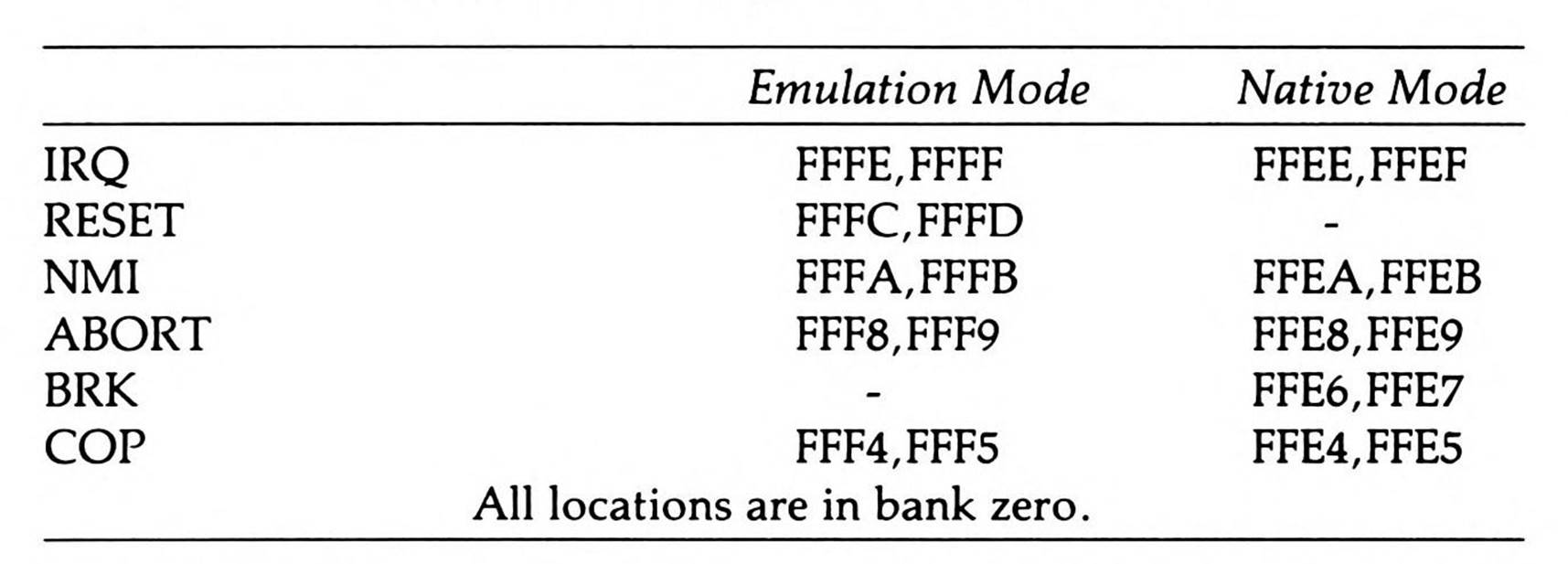
As discussed earlier in this chapter, native mode frees up the b bit in the status register by giving the break instruction its own vector. When a BRK is executed, the program counter and the status register are pushed onto the stack and the program counter is loaded with the address at $FFE6, the break instruction vector location.
The reset vector is only available in emulation mode because reset always returns the processor to that mode.
The 65816/65802, in both emulation and native modes, also provides a new coprocessor interrupt instruction to support hardware coprocessing, such as by a floating point processor. When the COP instruction is encountered, the 65802's interrupt processing routines transfer control to the co-processor vector location.
Finally, the pinout on the 65816 provides a new abort signal. This lets external hardware prevent the 65816 from updating memory or registers while completing the current instruction, useful in sophisticated memory-management schemes. An interrupt-like operation then occurs, transferring control through the special abort vector.
The 65802 Native Mode
For all that the 65816 is, it is not pin-compatible with the 6502 and 65C02. You can't just replace the earlier chips with it. It is here that the other version of this chip, the 65802, comes into its glory. The price, of course, is that the 65802 has the same addressability limitations as the 6502 and 65C02.
Figure 4.3 shows the programming model for the 65802's native mode. The bank registers, while they exist, do not modify addressability, so they are shown as eight-bit entities. All registers have been scaled back to sixteen bits. There is only one bank a 65802 can address; since it holds the direct page, the stack pointer, and the interrupt vectors (bank-zero features on the 65816), you can consider the 65802's bank to be bank zero. Otherwise, the programming model is identical to the 65816's.
The bank registers are an anomaly. They have no function because the packaging provides no pins to connect them to. But they exist because, inside the packaging, the chip itself is a 65816. In fact, you can change their value just as you would on the 65816, with a pull instruction, a long jump or JSR, an interrupt, or a long return, either from subroutine or from interrupt. Furthermore, every interrupt and return from interrupt pushes the program bank byte onto the stack or pulls it off, just like the 65816 does. But the bank register values are ignored (stripped from 24-bit addresses when they're sent to the sixteen-bit output pins).
The long addressing modes also seem misplaced here. You can execute instructions using long addressing on the 65802, but the bank addresses are, again, ignored. They are certainly an inefficient method for undertaking intrabank accesses and transfers, since they take up extra bytes for the bank address, and use up extra cycles in translation. Still, they cause the 65802 no problems, as long as you understand that the bank value is disregarded and only the remaining sixteen bits of address are effective in pointing to an address in the 65802's single addressable bank of memory.
65802 Native Mode Programming Model
(16-bit accumulator & index register modes: m=0 & x=0)
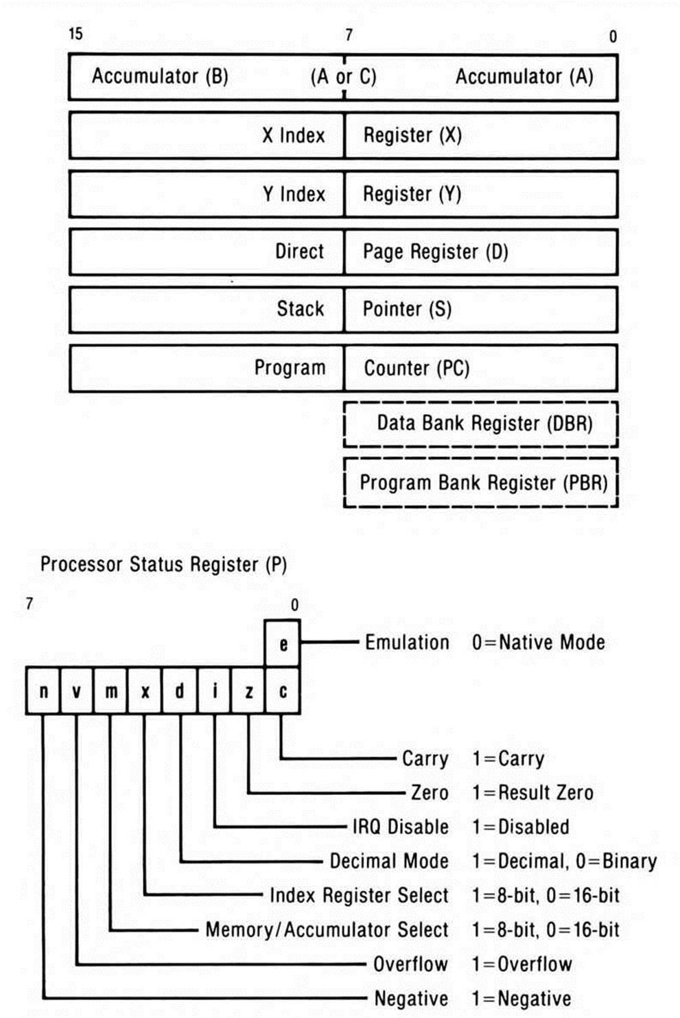
Figure 4.3. 65802 Native Mode Programming Model.
Finally, the bank bytes specified to the block move instructions are ignored, too. Block moves are by necessity entirely intrabank on the 65802.
Because the abort signal was designed into the 65816 by virtue of its redesigned pinout, its vector exists on the 65802 but has no connection to the outside world. Since there is no way to abort an instruction without using the external pin, the abort operation can never occur on the 65802.
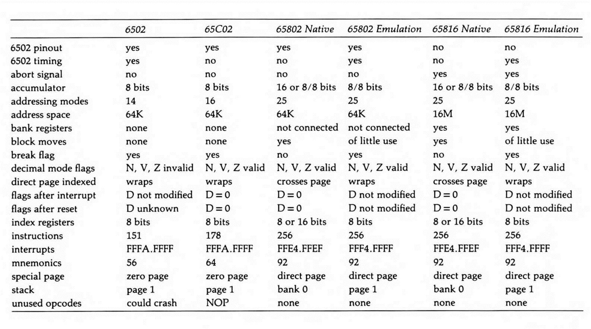
In all other respects, the 65802 and 65816 are identical, so the 65802 can almost be thought of as a 65816 in a system with only 64K of physical memory installed. Table 4.6 summarizes the differences between the 65802 and 65816 native modes and the 6502 and 65C02.
Emulation Mode
That the 65802 provides a pinout the same as the 6502's and the 65C02's is not enough to run all the software written for the earlier two processors. For one thing, the eight-bit software expects interrupt handlers to distinguish break instructions by checking the stacked break flag, and the 65802's native mode has no break flag, having replaced both it and the 6502's unused flag with the m and x flags. For another, 6502 instructions that use eight-bit registers to set the stack would set only half of the sixteen-bit stack. The native mode interrupt vectors are different from their 6502/65C02 counterparts, as Table 4.5 showed. There are also little differences; for example, while the direct page can be set to the zero page, direct page indexed addresses can cross pages in native mode, but wrap on the 6502 and 65C02.
Reaching beyond hardware compatibility to software compatibility was clearly so important that the designers of the 65802 and 65816 devised the 6502 emulation mode scheme. Both processors power-on in emulation mode, with the bank registers and the direct page register initialized to zero. As a result of both this and having the same pinout, a 65802 can be substituted for a 6502 in any application and will execute the existing software the same. Furthermore, it is possible to design second-generation 65816 systems compatible with existing 6502 designs which, provided the computer's designers do as good a job in providing compatibility as the 65816's designers have, could run all the existing software of the first generation system in emulation mode, yet switch into native mode for sixteen-bit power and 24-bit addressing.
It is important to realize, however, that 6502 emulation mode goes far beyond emulating the 6502. It embodies all the addressing mode and instruction enhancements of both the 65C02 and the 65802/65816; it has a fully relocatable direct page register; it provides the stack relative addressing modes; and in the 65816's emulation mode, it can switch between banks to use 24-bit addressing. The primary differences between native and emulation modes are limitations placed on certain emulation mode registers and flags so that existing programs are not surprised (and crashed) by non-6502-like results. These differences are summarized in Table 4.6.
Table 4.6 . Major Differences Between Processors and Modes.
The pair of 65816 instructions that have little use in emulation mode are the block move instructions. Because the source and destination parameters for moves are passed to the instruction in the index registers, their eight-bit limits confine the instruction to the zero page: a block can only be moved from one zero page location to another.
Only in emulation mode do 65802/65816 interrupt vectors match their 6502/65C02 counterparts. Native mode interrupt vectors have their own locations, as Table 4.5 showed.
Emulation Mode Registers
The 65802/65816, under emulation mode, has the same six registers as the 6502/65C02. In addition, all of the new 65802/65816 registers are available in some form, although some of these on a limited basis. Figure 4.4 shows the result.
The primary accumulator A is always limited to eight bits by lack of an m flag, but the hidden eight-bit accumulator B is available, as with the native mode eight-bit accumulator setting. For certain register-transfer operations, the two are combined to form the sixteen-bit register C, just as in native mode. The index registers are limited to eight bits by lack of an x flag. The direct page register is fully functional, although direct page indexing wraps rather than crossing into the next page. The stack pointer is curtailed to page one, as on the 6502 and 65C02; if a sixteen-bit value is used to set it, the high byte is ignored. Finally, there are the two bank registers, which are initialized to zero, but which can be changed to point to other banks.
Now look at the P status register. In addition to the eight bits of the standard 6502/65C02 status register, you'll see the ninth "phantom" e bit, which contains a one; this setting puts the processor into its 6502 emulation mode.
The A and B registers, which together make up the native mode sixteen-bit accumulator, are used together in emulation mode as C solely for transferring values to and from the direct page register and the stack.
The direct page register (D) points to the beginning of direct page memory. You'll probably normally set it to zero in the emulation mode to make the direct page identical to 6502 zero page memory. This is particularly true if your 65802 program is running within a 6502 or 65C02 operating system. The operating system will have stored values to zero page memory; if you change the direct page to point to another page, then call an operating system routine, the operating system will load its information from the wrong direct page (any page other than the zero page) and fail miserably.
65816 Emulation Mode Programming Model
 (A)
(A)
Figure 4.4. 65816 Emulation Mode Programming Model.
Switching Between 6502 Emulation and Native Modes
As you've seen, the native mode and the 6502 emulation mode embody a number of significant differences. When running the 65802 in an older machine, such as the Apple //c, //e, or II Plus, you will probably call your 65802 programs from a 6502 operating system or program. Your 65802 code can immediately switch the processor into native mode, so you can take advantage of the additional power. You must, however, switch back to emulation mode to use any I/O routines, or to call the 6502-based operating system.
Understanding the transitions between the two modes is critical, particularly in an environment where you are switching back and forth between 6502 systems programs and your own 65802 code.
Switching from Emulation to Native Mode
When the 65802 is switched from emulation to native mode, the value in the status register's carry bit winds up being toggled. Native mode is set by swapping a cleared carry bit with the current value in the emulation bit (which was a one if the processor was in emulation mode). The m and x flags in the status register are switched into place (replacing the b break flag) and the processor automatically forces the flags to one, which leaves the accumulator and index registers as eight-bit registers, the same as they were in emulation mode. The rest of the bits in the status register remain the same.
While the emulation mode stack pointer register is only an eight-bit register, it can be thought of as a sixteen-bit register with its high byte hard-wired to one, so that the emulation stack is always in page one. When the 65802 is switched from emulation to native mode, the sixteen-bit native mode stack pointer assumes the same value the emulation mode stack pointer has been pointing to—a page one address.
All other registers make the transition unchanged.
Switching from Native to Emulation Mode
Switching from native to emulation mode also toggles the carry. The carry bit is set, then exchanged with the emulation bit to force the processor back into emulation mode. Provided the processor was previously in native mode, the carry flag is cleared. The status register's mand x bits disappear, forcing the accumulator and index registers back to eight bits. If the index registers were in sixteen-bit mode, they keep their low bytes, but their high bytes are permanently lost. If, on the other hand, the accumulator was in sixteen-bit mode, the low byte remains in accumulator A while the high byte remains accessible as the hidden accumulator B. The m bit (bit five) returns to its emulation role as the break flag; the x bit (bit four) becomes once again an unused flag.
The stack is truncated from sixteen to eight bits, with its high byte forced to a one; that is, the stack is forced to page one. Any value in the high byte of the stack pointer register is permanently lost, which means you must be very careful not to “lose" a non-page-one stack. Solving this and other sticky problems involved with calling an emulation mode routine from native mode is the goal of one of the routines in Chapter 14.
All other registers make the transition unchanged.
65802/65816 Bugs and Quirks
As on the 65C02, the 6502's bugs are corrected by the 65802. Unlike the 65C02, however, the 65802 fixes the bug either only in native mode or without modifying the 6502's cycle counts (as the 65C02 in some cases does). There are no unused opcodes on the 65802, although there is an opcode which, while technically "used," is really reserved. If executed, it acts like a no-operation instruction.
The most anomolous feature of the 65816 is the behavior of new opcodes while in the 6502 emulation mode. While strict 6502 compatability is enforced for all 6502 and 65C02 opcodes, this is not the case with new opcodes. For example, although the high byte of the stack register is always set to one, wrapping of the stack during the execution of a single non-6502 instruction is not supported. These issues are discussed more fully in Chapter 16.
Because the 65802 fixes the 6502's bugs and quirks while leaving that chip's timing cycles untouched, the 65802 is in fact a hair more compatible as an upgrade chip than is the 65C02.
All materials on the site are licensed Creative Commons Attribution-Sharealike 3.0 Unported CC BY-SA 3.0 & GNU Free Documentation License (GFDL)
If you are the copyright holder of any material contained on our site and intend to remove it, please contact our site administrator for approval.
© 2016-2026 All site design rights belong to S.Y.A.