Sams Teach Yourself Arduino Programming in 24 Hours (2015)
Part III: Arduino Applications
Hour 17. Communicating with Devices
What You’ll Learn in This Hour:
![]() The different types of serial communication protocols
The different types of serial communication protocols
![]() Using the serial interface pins on the Arduino
Using the serial interface pins on the Arduino
![]() How the SPI interface works
How the SPI interface works
![]() How to talk to another device using I2C
How to talk to another device using I2C
More likely than not, you’ll run into a situation where you want your Arduino to communicate with some type of external device. Whether you’re interfacing your Arduino with the serial monitor tool in the Arduino IDE or passing data to an LCD controller to display information, communication is a vital part of working with the Arduino. This hour takes a look at three common methods of communicating with an Arduino.
Serial Communication Protocols
The basic mode of communication among Arduino devices is serial communication. Serial communication requires a fewer number of connections between the devices than other communication protocols (often with just two or three lines), and provides a simple way to move data between disparate devices.
The Arduino hardware design includes three different types of serial communication methods:
![]() A standard serial port
A standard serial port
![]() A Serial Peripheral Interface (SPI) port
A Serial Peripheral Interface (SPI) port
![]() An Inter-Integrated Circuit (I2C) port
An Inter-Integrated Circuit (I2C) port
These are all common serial communication methods used in the electronics industry. By providing all three methods, the Arduino developers have made it easy to connect your Arduino with just about any type of external device you’ll run into. The Arduino IDE software even includes libraries that make it easy for you to interface with each of these different communication methods in your sketches.
The following sections examine each of the different serial communication methods, showing you how to use each of them in your sketches.
Using the Serial Port
Each Arduino model contains at least one standard serial port interface. The serial port interface sends data as a serial sequence of bits to the remote device. Because data is sent one bit at a time, the serial port only needs two pins to communicate—one to send data to the remote device, and one to receive data from the remote device.
This is the interface that the Arduino IDE software uses to transfer data into your Arduino unit, as well as receive simple output from your Arduino unit. You can easily adapt the standard serial interface to communicate with other serial devices as well.
The Serial Port Interfaces
The serial interface on the Arduino uses two digital interface pins for serial communication with external devices. By default, all Arduino models use digital interface pins 0 and 1 to support the primary serial interface. The Arduino uses pin 0 as the receive port (called RX), and pin 1 for the transmit port (called TX).
The Arduino software names this port serial, which is also the name of the object you use in your sketches to send and receive data using the port (such as when you used the Serial.print function in your sketches).
Because the serial interface is commonly used to transfer your sketch code into the Arduino, to make life even easier for us the Arduino developers connected the serial interface pins to a serial-to-USB adapter built in to the Arduino unit. This is what allows you to plug your Arduino directly into to your workstation using a standard USB cable.
Watch Out!: Using the USB Serial Interface
Because the USB serial interface uses digital interfaces 0 and 1, you can’t use those interfaces in your sketches as digital inputs or outputs once you use the Serial.begin function to initialize the serial interface to output data to the serial monitor. You can use theSerial.end function to stop the serial interface and return the interfaces back to their normal functions.
The Arduino Due and Mega models also include three other serial port interfaces. Digital interface pins 18 and 19 are used for the Serial1 port, pins 16 and 17 for Serial2, and pins 14 and 15 are used for Serial3. These serial ports don’t have a serial-to-USB adapter connected to them, so you’ll either need to provide your own, or just use the raw serial pins in your circuits.
Because the serial ports use two separate pins to communicate, you have to be careful how you connect the Arduino serial port to other devices. If you connect your Arduino to another Arduino unit, or another type of serial device using the serial port, remember to cross-connect the interface pins. The receive pin on the Arduino must connect to the transmit port on the external device, and vice versa, as shown in Figure 17.1.
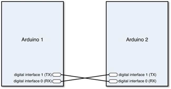
FIGURE 17.1 Connecting two Arduino units using the serial interface pins.
The Arduino sends and receives serial signals using Transistor-transistor-logic (TTL)-level voltages. This means that the 1 bit is represented by +5 volts, and a 0 bit is represented by 0 volts. Make sure that the remote device you connect to your Arduino serial interface also supports TTL-level signaling.
Watch Out!: RS-232 Serial Interfaces
Don’t try to connect your Arduino serial port to a standard RS-232 serial interface, such as what is found in the COM ports on older desktop workstations. The RS-232 interface standard uses +12V for the signal, which will damage the digital interfaces on your Arduino!
The Serial Library Functions
The Serial library provides a set of functions for you to easily send and receive data across the serial interfaces on your Arduino. You’ve already seen them in action as we used the serial interface to send data to the serial monitor utility in the Arduino IDE.
Not only can you send data out the serial interface, but the Serial library also includes functions that enable you to read data received on the serial interface. This allows you to send data from the serial monitor back into your Arduino sketch to control things. This is a great way to push data into your sketch as it runs.
Table 17.1 shows the functions provided by the Serial library that you can use in your sketches.
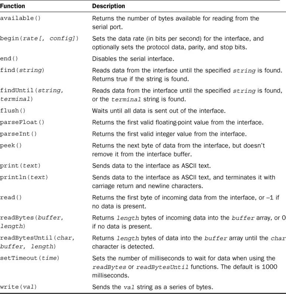
TABLE 17.1 The Serial Functions
You’ve already seen some of these functions in action as we worked on the experiment sketches in the previous hours. The following sections go through a brief rundown of the more commonly used Serial functions that you’ll want to use in your sketches.
Starting Communications
As you’ve already seen in our experiment sketches, to start communicating using the serial interface, you must use the Serial.begin function. This function initializes the digital interface pins for serial mode, and sets the communication parameters that the serial interface uses:
Serial.begin(rate[, config]);
The first parameter is required; it sets the speed of the data transfer in bits per second (called the baud rate). The Arduino serial interface supports baud rates up to 115,200 bits per second, but be careful, because using higher baud rates can sometimes introduce errors, especially in longer connection wires. It’s common practice to use 9600 baud to communicate with the serial monitor in the Arduino IDE.
The second parameter is optional; it defines the data bits, parity, and stop bits of the serial protocol. If you omit the second parameter, the serial interface uses an 8-bit serial protocol, with no parity and 1 stop bit. This is the standard used by most serial communications devices. If the serial device you use requires a different setting, you can use labels to define the settings for the second parameter. For example, to use a 7-bit protocol with even parity and 1 stop bit, you use the label SERIAL_7E1 for the second parameter.
Sending Data
Three separate functions send data to a remote device:
![]() Serial.print
Serial.print
![]() Serial.println
Serial.println
![]() Serial.write
Serial.write
The Serial.print function sends data as ASCII text. The ASCII format is commonly used for displaying data, which is what the Arduino IDE serial monitor uses. For numeric values, you can specify an optional second parameter, which defines the numeric format to use: BIN for output as a binary value, DEC for decimal format, HEX for hexadecimal format, and OCT for octal format. The default is decimal format.
The Serial.println function works the same as the Serial.print function, but adds the carriage return and line feed characters to the end of the output, creating a new line in the output window.
The Serial.write function allows you to send 1 byte of raw data to the remote device, without any formatting.
Receiving Data
The serial interface on the Arduino contains a buffer, holding data as the Arduino receives it on the RX pin. It can store up to 64 bytes of data, which allows you some flexibility in how your sketch retrieves the incoming data.
Your sketch can retrieve data from the buffer 1 byte at a time using the Serial.read function. Each time you read a byte from the buffer, the Arduino removes it from the buffer and shifts the remaining data over.
You can also retrieve multiple bytes of data from the buffer at a time. The Serial.readBytes function lets you specify the number of bytes to extract from the buffer and place them in an array variable in your sketch. The Serial.readBytesUntil function extracts data until a character that you specify is detected in the buffer data. That comes in handy if you send text data using a carriage return and line feed format for each line of data.
The Serial.parseInt or Serial.parseFloat functions provide ways for you to easily retrieve integer or floating-point values that you pass into your Arduino sketch as it runs. The next section shows an example of how to pass numeric values to your sketch and then retrieve them using the Serial.parseInt function.
Testing the Serial Port
Let’s go through an example of sending data from the serial monitor to a running sketch to demonstrate how to use the receive features of the serial interface.
![]() Try It Yourself: Sending Data to Your Arduino
Try It Yourself: Sending Data to Your Arduino
In this experiment, you control the blink rate of an LED by sending numeric values to your sketch using the Arduino IDE serial monitor. It uses the built-in LED connected to digital interface pin 13 on the Arduino, so you won’t need to build an external circuit.
Here are the steps to create the code for the experiment:
1. Open the Arduino IDE.
2. Select Sketch from the menu bar, then select Import Library, and then select the Timer One library. (If you don’t see the Timer One library listed, go to Hour 16, “Adding Interrupts,” to see how to add it to the Arduino IDE library.)
3. Enter this code into the editor window:
#include <TimerOne.h>
int state = 0;
int value;
long int newtime;
void setup() {
Serial.begin(9600);
pinMode(13, OUTPUT);
digitalWrite(13, state);
Serial.println("Enter the blink rate:");
}
void loop() {
if (Serial.available()) {
value = Serial.parseInt();
Serial.print("the blink rate is: ");
Serial.println(value);
Serial.println("Enter a new blink rate:");
newtime = value * 1000000;
Timer1.initialize(newtime);
Timer1.attachInterrupt(blinkme);
}
}
void blinkme() {
state = !state;
digitalWrite(13, state);
}
4. Save the sketch code as sketch1701.
5. Click the Upload icon to verify, compile, and upload the sketch to your Arduino unit.
6. Open the serial monitor utility to run the sketch and view the output. Make sure that the Line Speed drop-down box at the bottom is set for 9600 baud, and that the Line Ending drop-down box is set to No Line Ending.
7. In the text box at the top of the serial monitor, enter a number from 1 to 9, and then click the Send button.
8. Watch the LED blink at the rate that you specified in the serial monitor text box. You can submit new values to watch the rate change.
The sketch uses the Serial.available function to detect when new data is present in the serial interface buffer. It then uses the Serial.parseInt function to retrieve the data and convert it into an integer value. The sketch then uses the value in a timer interrupt (see Hour 16) to change how frequently the Arduino turns the LED on and off.
Tip: Serial Events
Reading data from the serial interface can sometimes be tricky, especially if you don’t know exactly when to expect the data to arrive. Instead of using the Serial.available function to poll the serial interface for data, you can use serial events to notify your sketch when data is present.
Incoming serial data triggers a special function named serialEvent, which you can define in your sketch. You can include code in the serialEvent function to process the data as it comes in, and then return back to your normal sketch code, much like the interrupts shown in Hour 16.
Working with the SPI Port
The Serial Peripheral Interface (SPI) protocol uses a synchronous serial connection to communicate with one or more peripheral devices over a short distance. A synchronous serial connection requires a separate clock signal to synchronize the data transfer between devices. Many sensors use the SPI protocol to communicate with a host system. You can use the SPI port on your Arduino to interface with those types of sensors.
The SPI protocol uses a bus technology to share a single interface between multiple devices. One device connected to the bus is designated as the master and controls the operation of the bus. The other devices connected to the bus are designated as slaves and can send or receive signals on the bus only when polled by the master device.
Watch Out!: The Arduino and SPI Slave Mode
The Arduino hardware supports both master and slave mode in SPI, but at the time of this writing, the Arduino library only supports operating in master mode on the SPI bus. This means that you cannot currently use your Arduino to communicate with other SPI master devices, only SPI slave devices, such as sensors.
The following sections describe how to use your Arduino as an SPI master device to communicate with SPI slave devices, such as sensors.
The SPI Interfaces
The SPI protocol uses three signals that connect to all devices in the SPI bus:
![]() MISO (Master In Slave Out): Line for slave sending data to the master device.
MISO (Master In Slave Out): Line for slave sending data to the master device.
![]() MOSI (Master Out Slave In): Line for the master device sending data to the slave.
MOSI (Master Out Slave In): Line for the master device sending data to the slave.
![]() SCK: A serial clock signal to synchronize the data transfer.
SCK: A serial clock signal to synchronize the data transfer.
Besides the three bus lines, each slave device has a Slave Select (SS) pin that connects to the master. The master must set the appropriate slave SS pin to a LOW value when it communicates with that specific slave device. If the SS pin is set to HIGH, the slave device ignores any data on the MOSI line.
The Arduino supports SPI signals using an interface that’s separate from the standard header pins. All Arduino devices include a separate ICSP header on the far-right side of the unit, as shown in Figure 17.2.
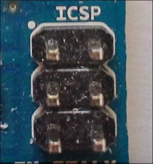
FIGURE 17.2 The ICSP header on the Arduino Uno unit.
Figure 17.3 shows the pin location for the SPI signals on the ICSP header.
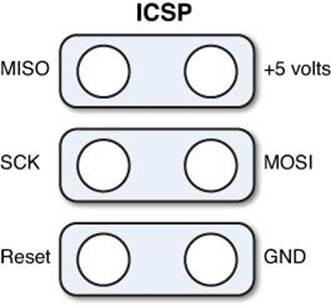
FIGURE 17.3 The SPI signals on the ICSP header.
The Arduino Uno also provides the SPI signals on the digital interface header pins:
![]() SS on digital interface 10
SS on digital interface 10
![]() MOSI on digital interface 11
MOSI on digital interface 11
![]() MISO on digital interface 12
MISO on digital interface 12
![]() SCK on digital interface 13
SCK on digital interface 13
If you use those interfaces to support SPI communication, you can’t use them as digital inputs or outputs.
By The Way: SPI and Digital Interfaces
When you initialize the SPI feature on the Arduino, you won’t be able to use the digital interfaces assigned to the SPI signals as inputs or outputs. That includes the built-in LED connected to digital interface 13.
The SPI Library Functions
The Arduino IDE software includes a separate SPI library by default. The SPI library contains functions required to communicate with SPI slave devices using your Arduino, but doesn’t provide any functions for the Arduino to act as a slave device itself. Table 17.2 lists the functions available in the SPI library.
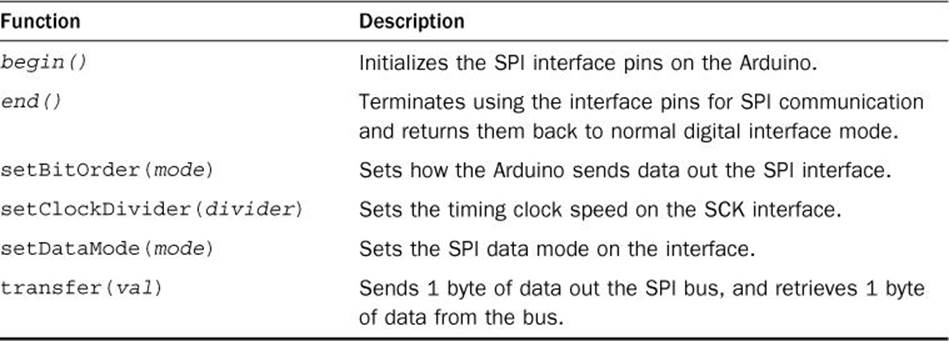
TABLE 17.2 SPI Functions
The SPI bus transfers data 1 byte at a time. You must use the SPI.setBitOrder function to set whether the Arduino handles the byte in least-significant bit order (LSBFIRST) or most-significant bit order (MSBFIRST).
The SPI.setClockDivider function determines the clock speed set for the SPI bus. The clock speed on the master and slave devices must match or you won’t get the proper data synchronization. The SPI library allows you to set the SPI bus clock speed to even number divisions of the Arduino microcontroller clock, which is 16MHz. You specify the clock speed using labels, such as SPI_CLOCK_DIV2 to set the clock speed to 8MHz (half of the Arduino 16MHz clock speed), or SPI_CLOCK_DIV4 to set the clock speed to 4MHZ. The parameter supports values of 2, 4, 8, 16, 32, 64, or 128.
The SPI.setDataMode function sets the clock polarity and phase used in the SPI bus. The SPI bus can use four standard data modes. All devices on the bus must be set to use the same mode. The values you can use are SPI_MODE0, SPI_MODE1, SPI_MODE2, and SPI_MODE3. You will need to consult with the specifications for the SPI device you’re communicating with to determine the mode it uses and set the Arduino to use the same SPI mode.
After you have all the SPI bus parameters set, you’re ready to send and receive data on the SPI bus. The SPI.transfer function both sends and receives a single byte of data on the bus with one function. The SPI.transfer function pulls the SS interface low, so the slave device connected to that pin knows to read the data that the Arduino sends on the bus. This means you can only communicate with one SPI device from most Arduino models. The Arduino Due supports three SPI interfaces, allowing you to connect up to three SPI slave devices.
Working with I2C
The I2C protocol was developed by the Phillips Semiconductor Corporation for providing a communication protocol between multiple embedded electronic devices using only a two-wire bus system. The I2C protocol is intended for very short distances, often between devices placed on the same circuit board, but can also be used with short distance wired connections.
To eliminate the extra slave select line, the I2C protocol uses addresses to determine which data is intended for which device. Each slave device on the bus has a unique address assigned to it, and only responds to data sent to its own address, much like an Ethernet local-area network (LAN).
This section discusses the I2C support provided by the Arduino and demonstrates how to communicate between Arduino devices using the I2C protocol.
The I2C Interface
One of the selling features of the I2C protocol is that it requires only two signals:
![]() Serial data line (SDA): Sends the data between devices.
Serial data line (SDA): Sends the data between devices.
![]() Serial clock (SCL): Provides a clock signal to synchronize the data transfer.
Serial clock (SCL): Provides a clock signal to synchronize the data transfer.
The single data line is used to both send and receive data, so it’s important that the master device have full control over the bus at all times to prevent data collisions. Slave devices can only send data when prompted by the master device.
Unfortunately, the different Arduino models provide the two I2C signals on different interface pins, so you have to be careful when accessing the I2C signals on your specific Arduino unit. Table 17.3 shows where to find the I2C signals on the different Arduino models.
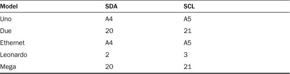
TABLE 17.3 I2C Interface Pins
Notice that the Uno and Ethernet models use two analog interface pins for the I2C signals instead of digital interface pins. The Due Arduino model also supports a second dedicated I2C interface pair. Those pins are labeled SDA1 and SCL1 on the board.
The Wire Library Functions
The Wire library provides software support for using the I2C interface on the Arduino. The Arduino IDE includes the Wire library by default, so it’s easy to use in your sketches. The Wire library provides all the functions that you need to set up and work with the I2C protocol in your sketches.Table 17.4 shows the functions that are available.
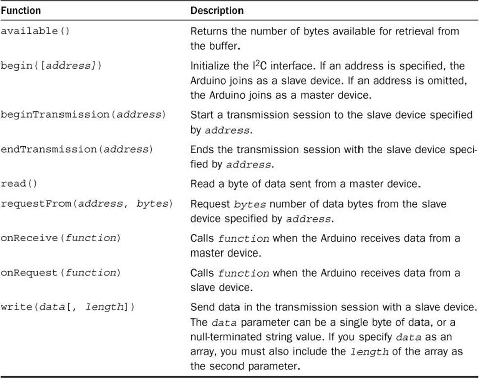
TABLE 17.4 Wire Functions
Every slave device on the I2C bus requires a unique address. To communicate on the bus as a slave device, you must assign your Arduino an address, specified in the begin function:
Wire.begin(1);
This statement sets the address of the Arduino to 1. Be careful when you assign an address to your Arduino that it doesn’t conflict with the address assigned to any other slave devices on the I2C bus. To operate as a master device, just use the begin function without specifying an address.
After the begin function, your Arduino can send and receive data messages from other devices on the I2C bus. Sending data to a device requires three separate statements. First, you must use the beginTransmission function to identify the slave device the data is intended for. Next, you use one or more write functions to send the actual data. Finally, you use the endTransmission function to tell the slave device you’re done talking to it.
Receiving data depends on whether the Arduino is operating in master or slave mode. If in slave mode, use the read function to retrieve the data sent from the master device on the bus. If the Arduino is operating in master mode, you need to use the requestFrom function to specify the address of the slave device to retrieve data from.
On the surface, using the I2C protocol can look somewhat complicated, but once you get the hang of the master and slave modes, it’s a breeze to send and receive data. The following section goes through an example of using the I2C protocol to communicate between two Arduino units.
Testing the I2C Interface
One great feature of the I2C bus is that you can use it to communicate between multiple Arduino units. You can then use one Arduino as the master and connect the others as slaves on the I2C bus. The master can request sensor data from each of the slaves to combine readings for logging or display purposes.
If you have two Arduino units handy (they don’t have to be the same model), you can work through this experiment.
![]() Try It Yourself: Communicating Between Arduino Units
Try It Yourself: Communicating Between Arduino Units
In this experiment, you set up an I2C bus to connect two Arduino units together so one Arduino can control the actions of another Arduino. The master Arduino unit will listen on the serial interface for an integer value and then pass that value to the slave Arduino using the I2C bus, which will use it to control the blink rate of the LED on digital interface 13.
Connecting two Arduino units sounds easy, but unfortunately you cannot just connect the I2C pins on the Arduino units directly together. The I2C bus protocol requires that the SDA and SCL lines be held at a HIGH voltage level when there isn’t any data on them. To do that, you need some equipment to set the pullup resistors:
![]() Two 1K-ohm resistors (color code brown, black, red)
Two 1K-ohm resistors (color code brown, black, red)
![]() Eight jumper wires
Eight jumper wires
![]() A standard breadboard
A standard breadboard
First, follow these steps to create the circuit to connect the two Arduino units:
1. Place the two 1K-ohm resistors on the breadboard so that one lead of each resistor connects to a common bus on the breadboard and the other leads connect to separate rails. The rails will carry the SDA and SCL bus signals.
2. Connect the common bus that has the two resistor leads on the breadboard to the 5V pin on the master Arduino using a jumper wire.
3. Connect the 5V pin of the slave Arduino to the same common bus using a jumper wire. The two Arduino units must share the same voltage reference for the bus signals to match.
4. Connect the GND pin of the master Arduino to the GND pin of the slave Arduino using a jumper wire. The two Arduino units must also share the same ground reference for the bus signals to match.
5. Connect the SDA signal pin on each Arduino (for the Uno, analog pin A4) to one of the bus rails on the breadboard that has the 1K-ohm resistor connected to it.
6. Connect the SCL pin on each Arduino (for the Uno, analog pin A5) to the other rail on the breadboard that has the 1K-ohm resistor on it.
Figure 17.4 shows the circuit diagram for this connection.
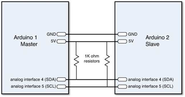
FIGURE 17.4 Circuit diagram for connecting the I2C bus pins on the Arduino units.
Watch Out!: Mismatched Arduinos
Be careful if you’re not using the same model of Arduino unit for both devices. The Arduino Due model only supports 3.3 volts, so you’ll have to use the 3.3V pin on the Arduino Uno if you want to connect it to an Arduino Due.
Next comes the tricky part—setting up the code for the master and slave Arduino units. Because each Arduino unit runs a different sketch, you must be careful when you connect the Arduino IDE that you’re loading the correct sketch into the correct Arduino.
If you connect each Arduino unit to a separate workstation, there’s no problem; you can just open the Arduino IDE on each workstation and enter the appropriate code for that Arduino unit. However, if you just have one workstation, you must be careful as to which one is which when connecting the Arduino units.
The easiest way to do that is to just connect one Arduino unit at a time to the workstation, program it, and then connect the other Arduino to program it.
First, connect the slave Arduino unit to the USB port, and then follow these steps:
1. Open the Arduino IDE.
2. Select Sketch from the menu bar, then Import library, and then select the Wire library.
3. Select Sketch again from the menu bar, then Import Library, and then select the Timer One library.
4. Enter this code into the editor window (the two #include directives should already be present from the import):
#include <Wire.h>
#include <TimerOne.h>
int state = 0;
int value;
long int newtime;
void setup() {
Wire.begin(1);
Wire.onReceive(gotRate);
pinMode(13, OUTPUT);
digitalWrite(13, state);
}
void loop() {
}
void gotRate(int howMany) {
if (Wire.available())
{
value = Wire.read();
newtime = value * 1000000;
Timer1.initialize(newtime);
Timer1.attachInterrupt(blinkme);
}
}
void blinkme() {
state = !state;
digitalWrite(13, state);
}
5. Save the slave sketch as sketch1702.
6. Click the Upload icon to verify, compile, and upload the sketch to the slave Arduino.
Now you’re ready to code the master Arduino unit. Disconnect the slave Arduino from the USB interface, and plug the master Arduino unit in. Follow these steps to code it:
1. Open the Arduino IDE.
2. Select Sketch from the menu bar, then Import Library, and then select the Wire library.
3. Enter this code into the editor window:
#include <Wire.h>
int value;
void setup() {
Serial.begin(9600);
Wire.begin();
Serial.println("Enter the blink rate:");
}
void loop() {
if (Serial.available()) {
value = Serial.parseInt();
Serial.print("the blink rate is: ");
Serial.println(value);
Wire.beginTransmission(1);
Wire.write(value);
Wire.endTransmission(1);
Serial.println("Enter a new blink rate:");
}
}
4. Save the code as sketch1703.
5. Click the Upload icon to verify, compile, and upload the code to the master Arduino unit.
6. Open the serial monitor to run the master program. Because you connected the 5V and GND pins of the two Arduino units together, the slave Arduino unit will receive power from the master Arduino unit plugged into the USB port. It might help to press the Reset button on the slave Arduino to ensure that it has restarted the slave sketch code properly.
7. Enter a numeric value from 1 to 9 in the text box at the top of the serial monitor, and click the Send button to send it to the master Arduino unit. The LED on the slave Arduino unit should begin to blink at the rate you entered.
The master Arduino unit uses the I2C bus to communicate the integer value you entered to the slave Arduino unit, which then uses it to set the TimerOne function interval to make the LED on digital interface 13 blink. That’s a pretty cool experiment!
Summary
This hour discussed how to communicate from your Arduino with other devices using serial protocols. The Arduino supports three separate serial protocols: the standard serial interface, the Serial Peripheral Interface (SPI), and the Inter-integrated Circuit (I2C) protocol. The standard serial interface uses one wire to send and another to receive data bits. The Arduino also includes a built-in serial-to-USB convertor that enables you to access the serial port using a USB cable. You can access the serial port using the Serial library provided in the Arduino IDE. The SPI protocol is available from the ICSP interface on the Arduino and uses three wires to communicate with external devices. You use the SPI library to access functions to send and receive data using the SPI port. Finally, the Arduino supports the I2C protocol using two interface ports and functions from the Wire library.
In the next hour, you’ll see how to interface your Arduino with different types of sensors for monitoring various conditions, including light, sound, and motion.
Workshop
Quiz
1. What Arduino IDE library should you use to work with the I2C interface on the Arduino?
A. The SPI library
B. The Wire library
C. The Serial library
D. The Interrupt library
2. You can connect the Arduino serial interface directly to a standard COM interface used in PC workstations. True or false?
3. What makes the I2C protocol different from the SPI protocol?
Answers
1. B. The Wire library contains the functions required to communicate with the I2C interface on the Arduino.
2. False. The COM interface used in Windows workstations uses a 12V signal reference, which is too large for the TTL-level serial port interface on the Arduino.
3. The I2C protocol assigns unique addresses to each slave device on the bus. The master device can communicate with a specific device by specifying its address.
Q&A
Q. How many sensors can an Arduino control on a single I2C bus?
A. The I2C protocol uses 7-bit addresses for slave devices, allowing you to assign addresses from 0 to 127. That means you can have up to 128 sensors on a single I2C bus.
Q. When the Arduino operates as a master device in an SPI bus, how does it communicate with more than one slave device? There’s only one SS pin that the master can control.
A. The Arduino can use any other available digital interface port for the SS pin to control a slave device. Just ensure that the port is held at a HIGH level by default and that the Arduino sets it to a LOW level when trying to send data to the slave device.
All materials on the site are licensed Creative Commons Attribution-Sharealike 3.0 Unported CC BY-SA 3.0 & GNU Free Documentation License (GFDL)
If you are the copyright holder of any material contained on our site and intend to remove it, please contact our site administrator for approval.
© 2016-2026 All site design rights belong to S.Y.A.