Sams Teach Yourself Arduino Programming in 24 Hours (2015)
Part I: The Arduino Programming Environment
HOUR 1 Introduction to the Arduino
HOUR 2 Creating an Arduino Programming Environment
HOUR 3 Using the Arduino IDE
HOUR 4 Creating an Arduino Program
Hour 1. Introduction to the Arduino
What You’ll Learn in This Hour:
![]() What the Arduino is all about
What the Arduino is all about
![]() The Arduino family of microcontrollers
The Arduino family of microcontrollers
![]() What programs you can run on an Arduino
What programs you can run on an Arduino
In just a short amount of time, the Arduino has taken the electronics world by storm. The concept of an open source hardware platform for creating microcontroller applications has sparked an interest in both hobbyists and professionals who are looking for simple ways to control electronic projects. This hour introduces you to the Arduino microcontroller family and walks through just what the excitement is all about.
What Is an Arduino?
The Arduino is an open source microcontroller platform that you use for sensing both digital and analog input signals and for sending digital and analog output signals to control devices. That definition is quite a mouthful. Before we delve into programming the Arduino, let’s take some time to look at what it’s all about. This section explores just what an Arduino is and how to use it in your electronics projects.
Arduino Is a Microcontroller
These days, just about everything has a computer built in. From toasters to televisions, it’s hard to find a device that doesn’t have some type of computer system controlling it.
However, the computer chip embedded in your toaster differs significantly from the computer chip used in your workstation. Computer chips embedded in household devices don’t need nearly as much computing power as those found in workstations. They mostly just need to monitor a few analog or digital conditions (such as the time or temperature) and be able to control a few devices (such as the heating elements in the toaster or the channel to display on the television).
Because embedded computers require less processing power, it doesn’t make any sense to use the same expensive high-powered computer chips found in workstations in our toasters and televisions. Instead, developers use less-expensive computer chips that have lesser processing power in those devices.
This is where microcontrollers come into play. A microcontroller is a computer chip with minimal processing power and that often is designed for automatically controlling some type of external device. Instead of having a large feature set and lots of components squeezed into the chip, microcontrollers are designed with simplicity in mind.
Because microcontrollers don’t need large processors, they have plenty of room on the chip to incorporate other features that high-powered computer chips use external circuits for. For example, most microcontrollers contain all their memory and input/output (I/O) peripheral ports on the same chip. This provides a single interface to all the features of the microcontroller, making it easier to incorporate into electronic circuits. Figure 1.1 shows a block diagram of a basic microcontroller layout.
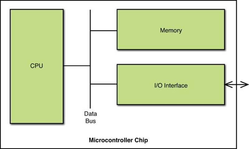
FIGURE 1.1 Block diagram of a microcontroller.
By incorporating the processor, memory, and I/O ports onto a single chip, microcontrollers provide a simple interface for designers to use when embedding them into projects.
Using Open Source Hardware
If you’ve heard of the Linux operating system, you’re probably familiar with the idea of open source software. In the world of open source software, a group of developers release the software program code to the general public so that anyone can make suggestions for changes and bug fixes. This often results in feature-rich software that has fewer bugs.
The idea of open source hardware is much the same, except with using physical hardware rather than software. With open source hardware projects, the physical hardware that you use to control devices is open to the general public to freely use and modify as needed.
The Arduino project developers have designed a full microcontroller system that uses a standard interface to interact with external devices. The design plans and architecture have been released to the public as open source, allowing anyone both to use the Arduino free of charge in their own projects and to even modify the Arduino without violating any patent or copyright laws.
Caution: Using the Arduino Name
Although the Arduino hardware is open source, the Arduino name enjoys trademark protection. Anyone can create his or her own device based on the Arduino hardware, but must refrain from naming it Arduino. Only the Arduino project can use the Arduino name in officially released versions of the Arduino project.
The next section walks through the basics of the Arduino architecture, showing just what makes up an Arduino.
Examining the Arduino Architecture
The developers with the Arduino project have built a completely self-contained microcontroller system on a single circuit board that you can plug into just about any embedded system. The core of the Arduino project is the microcontroller chip that it uses. To be able to program the Arduino, you’ll want to know a little about what’s going on “under the hood.”
The ATmega AVR Microcontroller Family
The Arduino developers selected the Atmel ATmega AVR family of microcontroller chips to power the Arduino. The ATmega AVR microcontroller is an 8-bit computer that contains several features built in:
![]() Flash memory for storing program code statements
Flash memory for storing program code statements
![]() Static random-access memory (SRAM) for storing program data
Static random-access memory (SRAM) for storing program data
![]() Erasable electronic programmable read-only memory (EEPROM) for storing long-term data
Erasable electronic programmable read-only memory (EEPROM) for storing long-term data
![]() Digital input and output ports
Digital input and output ports
![]() Analog-to-digital converter (ADC) for converting analog input signals to digital format
Analog-to-digital converter (ADC) for converting analog input signals to digital format
The ATmega AVR chip is a complete microcontroller system built in to a single chip. That allows the Arduino developers to create a small circuit board with minimal external components.
The Arduino series uses several different ATmega processors. Table 1.1 shows the different ATmega processors you’ll find in Arduino units.
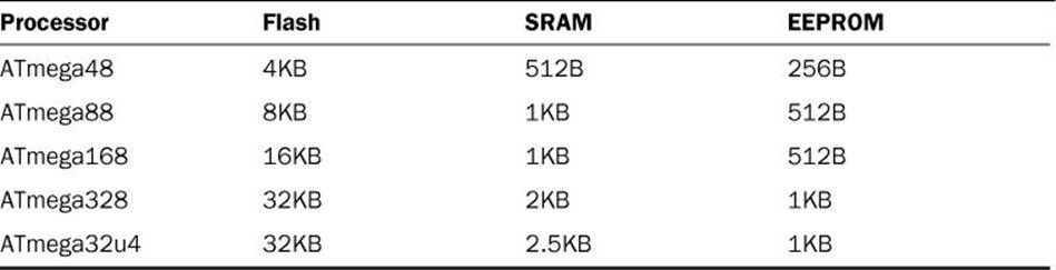
TABLE 1.1 The ATmega Processor Family
Compared to memory sizes used in workstation computers (often measured by the gigabit), the ATmega family of microcontrollers has very limited memory. However, the programs that you’ll need to create for a microcontroller are considerably simpler, so most of the time you won’t have to worry about the memory limitations.
The Arduino Layout
Another key to the Arduino is how it interfaces with external devices. The Arduino developers created a standard interface so that other developers could easily incorporate the Arduino directly into their projects. (This is part of the open source hardware method.)
The Arduino uses header sockets to make the input and output pins of the ATmega AVR chip available to external devices. Figure 1.2 shows the layout of the Arduino Uno.
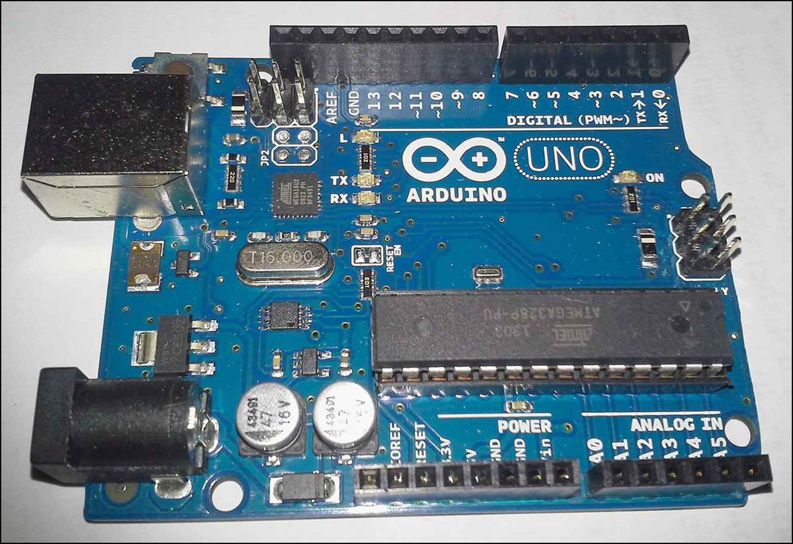
FIGURE 1.2 The Arduino Uno layout.
You can directly access all the microcontroller interfaces from the header sockets. The bottom set of sockets contain the analog input interfaces and access to the voltage and ground pins on the microcontroller. The top header socket contains the digital I/O interfaces. The standard layout of the header sockets allows developers to easily build plug-in devices (called shields) that interface with the Arduino.
Now that you’ve seen the basics of the Arduino, the next section takes a closer look at the different Arduino units available. There are plenty of different Arduino units to choose from for use in your projects, so knowing which one to use can sometimes be confusing.
Introducing the Arduino Family
If you’ve started looking for an Arduino unit to work with, you’ve probably noticed that there’s not just one Arduino. This section covers the history of the Arduino unit and why so many different versions of it are available.
The History of the Arduino
Interestingly enough, the Arduino wasn’t designed by a large electronics corporation or even by a group of computer science majors. Instead, it was designed out of necessity by a group of students and instructors looking for a solution to animate their art projects.
Modern art projects often require synchronized moving parts, which necessitates precise automation, which in turn, requires some type of microcontroller system.
Because most art students aren’t by nature programmers, having to purchase microcontroller chips and design electronic circuits to make them run became quite a challenge. A group of students at the Interaction Design Institute Ivera (IDII) in Italy worked on a project to help minimize the amount of coding art students had to write to automate their artistic creations.
This resulted in the Wiring project, which produced a standard microcontroller circuit board, along with a standard programming environment, called Processing. Created in 2003, the Wiring and Processing projects gained some acceptance, but were somewhat expensive for most students to experiment with.
After a few years of tweaking the Wiring project, in 2005 a group of designers led by Massimo Banzi and David Cuartielles came up with the Arduino project. The Arduino project built upon the basic features of the Wiring project, but at a lower cost for students.
Every part of the Arduino system was designed for simplicity for nontechnical people. The hardware interface is somewhat forgiving. For instance, if you hook up the wrong wires to the wrong ports, you won’t usually blow up your Arduino unit. If you do happen to manage to blow up the ATmega microcontroller chip, the Arduino was designed to easily replace the microcontroller chip without having to purchase an entire Arduino unit.
Likewise, the software for the Arduino was designed with nonprogrammers in mind. In an interesting tie to the art world, programs that you create for the Arduino are called sketches, and the folders where you store your sketches are called sketchbooks.
Exploring the Arduino Models
Part of the open source hardware method is to provide lots of options for developers. This allows developers to find just the right Arduino to fit into their project. The following sections walk through the different Arduino units currently available.
Arduino Uno
The workhorse of the Arduino family is the Uno. It’s the most popular Arduino unit and provides the basic functionality of the ATmega AVR microcontroller within the standard Arduino footprint.
It uses an ATmega328 microcontroller, which provides 14 digital I/O interfaces, 6 analog input interfaces, and 6 pulse-width modulation (PWM) interfaces for controlling motors.
The Uno circuitry also contains a USB interface for communicating with workstations as a serial communications device, a separate power jack so that you can power the Arduino Uno without plugging it into a workstation, and a reset button to restart the program running on the Arduino.
The size and layout of the Arduino Uno has been made the standard format for most Arduino units, so just about all Arduino shields (discussed later in the “Exploring Arduino Shields” section) fit into the header sockets of the Arduino Uno.
Tip: Following Along with the Book
All the examples in this book use the Arduino Uno unit. If you want to follow along with the examples, ideally you should use the Arduino Uno, although the other full-sized Arduino units would work too, but with some modifications to the projects.
Arduino Due
The Arduino Due unit uses a more powerful 32-bit ARM Cortex-M3 CPU instead of the standard ATmega328 microcontroller. This provides significantly more processing power than the standard Arduino Uno.
The Due provides 54 digital I/O interfaces, 12 PWM outputs, 12 analog inputs, and 4 serial Universal Asynchronous Receiver/Transmitter (UART) interfaces. It also provides considerably more memory, with 96KB of SRAM for data storage, and 512KB of flash memory for program code storage.
The Arduino Due uses the standard Uno header layout, but adds another header along the right side of the unit, providing the extra interfaces. This allows you to use most shields designed for the Uno on the Due.
Arduino Leonardo
The Arduino Leonardo uses the ATmega32u4 microcontroller, which provides 20 digital I/O interfaces, 7 PWM outputs, and 12 analog inputs. The Arduino Leonardo has the same header layout as the Uno, with additional header sockets for the extra interfaces.
One nice feature of the Arduino Leonardo is that it can emulate a keyboard and mouse when connected to a workstation using the USB port. You can write code to run on the Arduino Leonardo that sends standard keyboard or mouse signals to the workstation for processing.
Arduino Mega
The Arduino Mega provides more interfaces than the standard Arduino Uno. It uses an ATmega2560 microcontroller, which provides 54 digital I/O interfaces, 15 PWM outputs, 16 analog inputs, and 4 UART serial ports. You can use all the standard Arduino shields with the Mega unit.
The Arduino Mega provides a lot more interfaces, but it comes at a cost of a larger footprint. The Arduino Uno is a small unit that can easily fit into a project, but the Arduino Mega device is considerably larger.
Arduino Micro
The Arduino Micro is a small-sized Arduino unit that provides basic microcontroller capabilities, but in a much smaller footprint. It uses the same ATmega32u4 microcontroller as the Lenardo, which provides 20 digital I/O interfaces, 7 PWM outputs, and 12 analog inputs.
The selling point of the Arduino Micro is that it is only 4.8cm long and 1.77cm wide, small enough to fit into just about any electronics project. It uses a USB port to communicate as a serial device with workstations, or as a keyboard and mouse emulator like the Lenardo can.
The downside to the Micro is that because of its smaller size, it doesn’t work with the standard Arduino shields, so you can’t expand its capabilities with other features.
Arduino Esplora
The Arduino Esplora is an attempt at creating an open source game controller. It uses the ATmega 32u4 microcontroller just like the Lenardo and Micro do, but also contains hardware commonly found on commercial game controllers:
![]() Analog joystick
Analog joystick
![]() Three-axis accelerator
Three-axis accelerator
![]() Light sensor
Light sensor
![]() Temperature sensor
Temperature sensor
![]() Microphone
Microphone
![]() Linear potentiometer
Linear potentiometer
![]() Connector for an LCD display
Connector for an LCD display
![]() Buzzer
Buzzer
![]() LED lights
LED lights
![]() Switches for up, down, left, and right
Switches for up, down, left, and right
The Esplora also has a unique design to help it fit into a game controller case that could be handheld, providing easier access to the switches and analog joystick.
Arduino Yun
The Arduino Yun is an interesting experiment in combining the hardware versatility of an ATMega32u4 microcontroller with an Atheros microprocessor running a Linux operating system environment. The two chips communicate with each other directly on the Yun circuit board, so that the ATmega microcontroller can pass data directly to the Atheros system for processing on the Linux system.
The Linux system also includes built-in Ethernet and Wi-Fi ports for external communication, in addition to a standard USB port to run a remote serial console. This is the ultimate in embedding a full Linux system with a microcontroller.
Arduino Ethernet
The Arduino Ethernet project combines the microcontroller of the Arduino Uno with a wired Ethernet interface in one unit. This enables you to interface with the Arduino remotely across a network to read data collected or to trigger events in the microcontroller.
LilyPad Arduino
The Arduino LilyPad is certainly an interesting device. It was designed for the textile arts world, embedding a microcontroller within textiles. Not only is it small, but it’s also very thin and lightweight, perfect for sewing within just about any type of fabric. Think of wearing a shirt with built-in LEDs that flash messages to your friends!
One interesting feature of the LilyPad Arduino is the built-in MCP73831 LiPo battery charging chip. This chip allows you to embed rechargeable batteries with the device; when the unit is plugged into a USB port of a workstation, the rechargeable batteries recharge automatically.
Examining the Arduino Uno
At the time of this writing, the Arduino Uno R3 is the current main board in the Arduino family. It’s the most commonly used unit for interacting with projects that require a simple microcontroller. The Uno R3 unit provides the following:
![]() 14 digital I/O interfaces
14 digital I/O interfaces
![]() 6 analog input interfaces
6 analog input interfaces
![]() 6 PWM interfaces
6 PWM interfaces
![]() 1 I2C controller interface
1 I2C controller interface
![]() 1 SPI controller interface
1 SPI controller interface
![]() 1 UART serial interface, connected to a USB interface
1 UART serial interface, connected to a USB interface
The Arduino Uno circuit board, shown back in Figure 1.2, uses the standard Arduino header socket layout.
The bottom row of sockets contains the analog input sockets on the right, along with sockets that provide power for external circuits on the left. Along the top of the Arduino are the digital I/O sockets.
The digital I/O sockets have a double use. Not only are they used for digital input or output signals, but some of them are used for secondary purposes, depending on how you program the ATmega microcontroller:
![]() Digital sockets 0 and 1 are also used as the RX and TX lines for the serial UART.
Digital sockets 0 and 1 are also used as the RX and TX lines for the serial UART.
![]() Digital sockets 3, 5, 6, 9, 10, and 11 are used for PWM outputs.
Digital sockets 3, 5, 6, 9, 10, and 11 are used for PWM outputs.
![]() The leftmost four sockets in the top header socket row are for the SPI controller interface.
The leftmost four sockets in the top header socket row are for the SPI controller interface.
Besides the header sockets, the Arduino Uno provides a standard USB port for connecting the unit to a workstation. The USB port uses the UART serial interface of the ATmega microcontroller to send data to the microcontroller. This is how you load programs into the Arduino. You can also use the USB serial interface to view output from the microcontroller, which comes in handy when debugging your Arduino sketches.
The Arduino Uno also has four built-in LEDs, shown in Figure 1.3, that help you see what’s going on in the Arduino:
![]() A green LED (marked ON) that indicates when the Arduino is receiving power
A green LED (marked ON) that indicates when the Arduino is receiving power
![]() Two yellow LEDs (marked TX and RX) that indicate when the UART serial interface is receiving or sending data
Two yellow LEDs (marked TX and RX) that indicate when the UART serial interface is receiving or sending data
![]() A yellow LED (marked L) connected to digital output socket 13 that you can control from your programs
A yellow LED (marked L) connected to digital output socket 13 that you can control from your programs
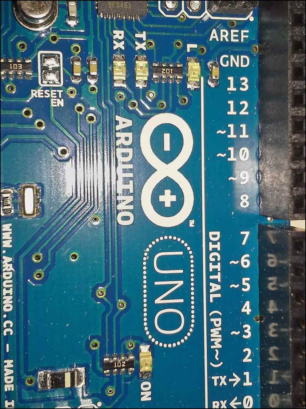
FIGURE 1.3 The Arduino Uno R3 LEDs.
Finally, one new addition to the R3 version of the Arduino Uno is a Reset button, located at the upper-left corner of the circuit board. Pressing the Reset button forces the ATmega microcontroller to reboot, which reloads the program code in memory and starts executing code from the beginning of the program.
Accessories You Might Need
Besides picking up an Arduino unit, you’ll also need to pick up a few other components to complete your project. This section identifies the more common parts you’ll need:
![]() A USB A-B cable: The Arduino USB port uses a B-type USB interface, so you’ll need to find an A-B USB cable to connect the Arduino to your workstation. Most printers use a B-type USB interface, so these cables aren’t hard to find.
A USB A-B cable: The Arduino USB port uses a B-type USB interface, so you’ll need to find an A-B USB cable to connect the Arduino to your workstation. Most printers use a B-type USB interface, so these cables aren’t hard to find.
![]() An external power source: After you program your Arduino, you probably don’t want to keep it tethered to your workstation. The Arduino Uno includes a 2.1mm center positive power jack so that you can plug in an external power source. This can either be an AC/DCV converter or a batter power pack that provides 5V power.
An external power source: After you program your Arduino, you probably don’t want to keep it tethered to your workstation. The Arduino Uno includes a 2.1mm center positive power jack so that you can plug in an external power source. This can either be an AC/DCV converter or a batter power pack that provides 5V power.
![]() A breadboard: As you experiment with interfacing various electronic components to your Arduino, a breadboard comes in handy to quickly build connections. Once you have your circuits designed, you can purchase prototype shields to make the interface connections more permanent (see Hour 24, “Prototyping Projects”).
A breadboard: As you experiment with interfacing various electronic components to your Arduino, a breadboard comes in handy to quickly build connections. Once you have your circuits designed, you can purchase prototype shields to make the interface connections more permanent (see Hour 24, “Prototyping Projects”).
![]() Resistors: Resistors are used for limiting the current through a circuit, usually to avoid burning out the microcontroller inputs or the LED outputs.
Resistors: Resistors are used for limiting the current through a circuit, usually to avoid burning out the microcontroller inputs or the LED outputs.
![]() Variable resistors: You can also use variable resistors (called potentiometers) to adjust the voltage going into an analog input socket to control a circuit.
Variable resistors: You can also use variable resistors (called potentiometers) to adjust the voltage going into an analog input socket to control a circuit.
![]() Switches: Switches allow you to provide a digital input for controlling your programs.
Switches: Switches allow you to provide a digital input for controlling your programs.
![]() Wires: You’ll need some wires for connecting the breadboard components together and interfacing them into the Arduino header sockets.
Wires: You’ll need some wires for connecting the breadboard components together and interfacing them into the Arduino header sockets.
![]() Sensors: You can interface a number of both digital and analog sensors into your Arduino. There are temperature sensors and light sensors, for instance, that produce varying analog outputs based on the temperature or amount of light.
Sensors: You can interface a number of both digital and analog sensors into your Arduino. There are temperature sensors and light sensors, for instance, that produce varying analog outputs based on the temperature or amount of light.
![]() Motors: Controlling moving parts requires some type of motor. The two main types of motors you’ll most often require are servo motors, which rotate to a fixed position, and DC motors, which can spin at a variable rate based on the voltage provided.
Motors: Controlling moving parts requires some type of motor. The two main types of motors you’ll most often require are servo motors, which rotate to a fixed position, and DC motors, which can spin at a variable rate based on the voltage provided.
Often you can find different Arduino kits that include these parts. The Arduino Store provides an official Arduino Starter Kit package, which includes an Arduino Uno R3 unit, a USB cable, a breadboard, and parts to create 15 separate projects (along with the tutorials on how to build them). This kit is a great way to get started with your Arduino unit.
Exploring Arduino Shields
The beauty of using open source hardware for your project is that plenty of other developers have already solved many of the same issues that you’ll run into and are willing to share their solutions. The standard interface to the Arduino provides a common way for developers to build external circuits that interface to the Arduino and thus provide additional functionality.
These units are called shields. There are plenty of Arduino shields available for a myriad of different projects. This section discusses a few popular shields.
Connecting with the Ethernet Shield
These days just about every project needs some type of network connectivity. Microcontroller projects can use a network to send data to a remote monitoring device, to allow remote connectivity to monitor data, or to just store data in a remote location.
The Ethernet shield provides a common wired network interface to the Arduino, along with a software library for using the network features. Figure 1.4 shows the Ethernet shield plugged into an Arduino Uno R3 unit.
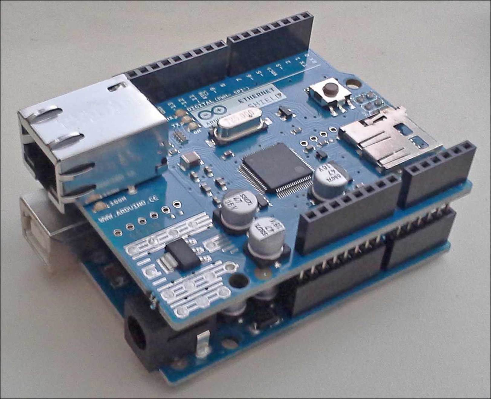
FIGURE 1.4 The Ethernet shield plugged into the Arduino Uno.
While the Ethernet shield plugs into the standard header sockets of the Arduino Uno, it also has the same standard header sockets built in, so you can piggy-back additional shields onto the Ethernet shield (so long as they don’t use the same signals to process data).
Displaying Data with the LCD Shield
Often, instead of connecting to the Arduino unit to retrieve information, it would be nice to just view data quickly. This is where the LCD shield comes into play.
It uses a standard LCD display to display 2 rows of 25 characters that you can easily view as the Arduino unit is running. The LCD shield also contains five push buttons, enabling you to control the program with basic commands.
Running Motors with the Motor Shield
A popular use for the Arduino is to control motors. Motors come in handy when working with robotics and when making your project mobile using wheels.
Most motors require the use of PWM inputs so that you can control the speed of the motor. The basic Arduino system contains six PWM outputs, enabling you to control up to six separate motors. The motor shield expands that capability.
Developing New Projects with the Prototype Shield
If you plan on doing your own electronic circuit development, you’ll need some type of environment to build your circuits as you experiment. The Prototype shield provides such an environment.
The top of the Prototype shield provides access to all the Arduino header pins, so you can connect to any pin in the ATmega microcontroller. The middle of the Prototype shield provides standard-spaced soldering holes for connecting electronic parts, such as resistors, sensors, diodes, and LEDs.
If you would like to experiment with your projects before soldering the components in place, you can also use a small solderless breadboard on top of the Prototype shield, which allows you to create temporary layouts of your electronic components for testing, before committing them to the soldering holes.
Summary
This hour covered the basics of what the Arduino is and how you can use it in your electronic projects. You first learned what microcontrollers are and how you can use them to sense digital and analog inputs and to output digital signals to control devices. The discussion then turned to the Arduino and how it uses the ATmega AVR microcontroller along with a standard interface to receive analog and digital signals and to send digital output signals. You then learned about the different Arduino shields available for adding functionality to your Arduino projects, such as connecting it to a network or using it to control motors and servos.
In the next hour, we take a closer look at what you need to start programming the Arduino.
Workshop
Quiz
1. Which type of memory should you use to store data that you can retrieve after the Arduino has been powered off?
A. Flash memory
B. SRAM memory
C. EEPROM memory
D. ROM memory
2. The Arduino requires a connection to a workstation to work. True or false?
3. Is Arduino shield available that allows your program to display simple information without requiring a connection to a computer?
Answers
1. C. The EEPROM memory is the only data memory built in to the Arduino that can retain data when the unit is powered off. The flash memory can also retain information after a power off, but it’s used only to store program code, not data.
2. False. All the Arduino models allow you to connect a battery or AC/DC converter to run the Arduino without it being plugged into a computer.
3. Yes, the LCD shield provides a 2-row, 25-character display that your Arduino programs can use to display simple data while running.
Q&A
Q. I’m new to electronics and don’t know what parts to get to work with my Arduino. Are there complete kits available that include the electronics required to run projects?
A. Yes, the Arduino project has a complete kit available that includes an Arduino Uno along with motors, an LCD display, sensors, and a breadboard and parts required to build 15 projects. You can find the kit, along with other Arduino units and shields, at various online retailers, such as AdaFruit, SparkFun, and Newark Electronics.
Q. Do you have to reprogram the Arduino each time you run it?
A. No, the Arduino stores the program in Flash memory, which retains the program code after a power off. You only have to load your program once, and the Arduino will retain it no matter how often you turn it on or off.
All materials on the site are licensed Creative Commons Attribution-Sharealike 3.0 Unported CC BY-SA 3.0 & GNU Free Documentation License (GFDL)
If you are the copyright holder of any material contained on our site and intend to remove it, please contact our site administrator for approval.
© 2016-2026 All site design rights belong to S.Y.A.