Sams Teach Yourself Arduino Programming in 24 Hours (2015)
Part III: Arduino Applications
Hour 21. Working with the Ethernet Shield
What You’ll Learn in This Hour:
![]() How to connect your Arduino to the network
How to connect your Arduino to the network
![]() How to connect to remote devices
How to connect to remote devices
![]() How to allow other devices to connect to your Arduino
How to allow other devices to connect to your Arduino
These days, just about everything is connected to a network. Using networks makes it easy to query data from a centralized server and to provide data to multiple clients. Being able to connect your Arduino to a network can open a whole new world of possibilities with monitoring sensors. You can connect your Arduino to Ethernet networks in a few different ways. This hour discusses these different ways and walks through an example of providing sensor data to network clients.
Connecting the Arduino to a Network
You can connect your Arduino to Ethernet networks a few different ways. If you already have an Arduino unit, you can use a couple of shields to easily add network capabilities. If you’re looking to purchase a new Arduino, there’s an Arduino model that includes a wired Ethernet connection built in. This section discusses the different options you have available for using your Arduino on an Ethernet network.
The Ethernet Shield
If you already have an Arduino device that uses the standard Arduino pin layout, you can use the Ethernet Shield to connect to a wired network. The Ethernet Shield provides an RJ-45 jack for Ethernet connections, and also includes an SD card reader to provide extra space for storing data.Figure 21.1 shows the Ethernet Shield plugged into an Arduino Uno device.
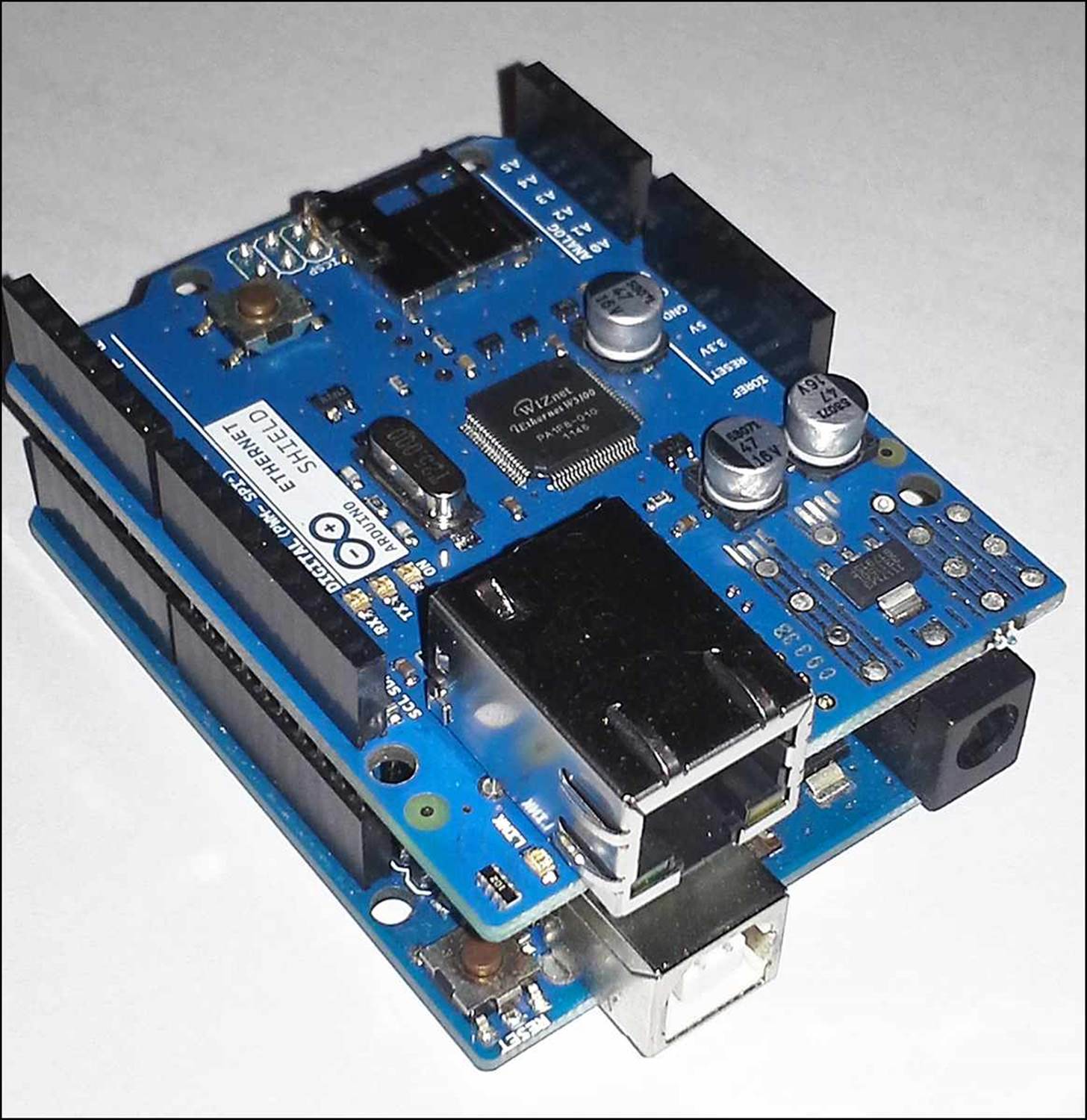
FIGURE 21.1 The Ethernet Shield.
The Ethernet Shield uses the Serial Peripheral Interface (SPI) communication protocol (see Hour 17, “Communicating with Devices”) to transfer data to the Arduino unit. The SPI interface uses digital interface pins 10, 11, 12, and 13 on the Arduino Uno, and pins 10, 50, 51, and 52 on the Arduino Mega unit.
A great feature of the Arduino Ethernet Shield is that it also supports the Power over Ethernet (PoE) feature. This feature allows the Ethernet Shield to get its power from network switches that support PoE. Therefore, if you have a PoE-capable network switch, you can power your Arduino and the Ethernet Shield directly from the network cable, without a separate power source.
Besides the PoE feature, the Ethernet Shield also includes pass-through header pins, so you can piggy-back additional shields on top of the Ethernet Shield, and it also has separate transmit and receive LEDs to indicate when it receives and sends data on the network.
The WiFi Shield
The WiFi Shield is another way to provide access to Ethernet networks, using wireless network access points. With the growing popularity of inexpensive home wireless network access points, the WiFi Shield can provide easy network access for your Arduino from any place. It supports both the 802.11b and 802.11g network protocols.
The WiFi Shield also uses the standard Arduino shield pin layout, so it plugs directly into most Arduino models. As with the Ethernet Shield, the WiFi Shield communicates using the SPI protocol, and requires the same digital interface pins (10, 11, 12, and 13 on the Uno; and 10, 50, 51, and 52 on the Mega). However, besides these pins, the WiFi Shield also uses digital interface pin 7 to communicate a handshake signal with the Arduino.
The WiFi Shield uses four LED indicators:
![]() Data (blue): Shows when data is being received or transmitted.
Data (blue): Shows when data is being received or transmitted.
![]() Error (red): Indicates a communication error on the network.
Error (red): Indicates a communication error on the network.
![]() Link (green): Shows when the network connection is active.
Link (green): Shows when the network connection is active.
![]() L9 (yellow): Connected to digital interface pin 9.
L9 (yellow): Connected to digital interface pin 9.
You can control the L9 LED as a status indicator from your sketch. This makes for a handy replacement of the pin 13 LED that’s on the Arduino board, because you won’t be able to see it with the shield plugged in.
The Arduino Ethernet Model
One Arduino model even has the Ethernet network built in to the device. The Arduino Ethernet model includes all the features of the Ethernet Shield (including an SD card reader), using an RJ-45 jack directly on the Arduino unit for the wired Ethernet connection.
The Arduino Ethernet unit mimics the layout of the standard Arduino Uno device. It includes 14 digital interface pins, but as with the Ethernet Shield, pins 10, 11, 12, and 13 are reserved for use with the Ethernet connection, leaving only nine digital interfaces that you can use in your sketches.
One downside to the Arduino Ethernet unit is that it doesn’t include a USB connector to interface with your workstation. Instead, it uses a six-pin serial interface port that requires a USB to serial adapter, which you have to purchase separately.
The Ethernet Shield Library
All three Arduino networking options each have their own libraries for writing sketches that can communicate with the network. They all contain similar functions, so this hour does not cover all three libraries. Instead, this discussion focuses on the functions available in the Ethernet Shield library to show you the basics of using your Arduino on the network.
The Ethernet Shield library is installed in the Arduino integrated development environment (IDE) by default, and consists of five different classes:
![]() The Ethernet class, for initializing the network connection
The Ethernet class, for initializing the network connection
![]() The IPAddress class, for setting local and remote IP addresses
The IPAddress class, for setting local and remote IP addresses
![]() The Client class, for connecting to servers on the network
The Client class, for connecting to servers on the network
![]() The Server class, for listening for connections from clients
The Server class, for listening for connections from clients
![]() The EthernetUDP class, for using connectionless User Datagram Protocol (UDP) messages with other devices on the network
The EthernetUDP class, for using connectionless User Datagram Protocol (UDP) messages with other devices on the network
Each class contains methods that help you interact with other network devices from the Ethernet Shield. The following sections show the methods contained in each class and how to use them.
Watch Out!: Referencing the Ethernet Library
If you select the Ethernet Library from the Arduino IDE Import Library feature, it will add #include directives for lots of different things, whether you use them in your sketch or not. This can make your sketch unnecessarily large. It’s usually best to just manually include the #include directives required for your sketch. For the examples used in this hour, you’ll only need the following:
#include <SPI.h>
#include <Ethernet.h>
The Ethernet Class
The Ethernet class contains three class methods:
![]() begin: Initializes the network connection.
begin: Initializes the network connection.
![]() localIP: Retrieves the IP address of the Ethernet Shield.
localIP: Retrieves the IP address of the Ethernet Shield.
![]() maintain: Requests a renewal of a Dynamic Host Control Protocol (DHCP) IP address.
maintain: Requests a renewal of a Dynamic Host Control Protocol (DHCP) IP address.
Every sketch that uses the Ethernet Shield must use the Ethernet class begin method to initialize the shield on the network. The begin method has one required parameter and four optional parameters:
Ethernet.begin(mac, [ip], [dns], [gateway], [subnet]);
In Ethernet networks, every device must have a unique low-level address, called the Media Access Control (MAC) address. The MAC address is usually expressed as a 12-digit hexadecimal number, often using colons or dashes to separate the numbers in pairs to make it easier to read. For example, my Arduino Ethernet Shield MAC address is shown on the sticker as follows:
90-A2-DA-0E-98-34
Newer Arduino Ethernet Shield devices are each assigned a unique MAC address and have a sticker with the address on the device. Older Ethernet Shield devices aren’t assigned a unique MAC address, so it’s up to you to assign one with the begin method. Just make sure that the address you use doesn’t match any other devices on your network.
Besides the MAC address, to interact on the network, your Arduino device will also need a unique IP address. The IP address identifies each network device within a specific subnetwork.
You can assign an IP address to a network device in two different ways:
![]() Manually assign a static address
Manually assign a static address
![]() Request an address from the network dynamically
Request an address from the network dynamically
The following two sections discuss how to use both types of address methods with your Ethernet Shield.
Static Addresses
For the static address method, you’re responsible for assigning a unique IP address to each device on your network. You do that by specifying both the MAC and IP addresses in the begin method:
Ethernet.begin(mac, ip);
You specify the MAC address using a byte array of hexadecimal values. For example:
byte mac[] = {0x90, 0xa2, 0xda, 0x0e, 0x98, 0x34 };
Unfortunately, you cannot specify the IP address as a string value. This is where the IPAddress class comes in. The IPAddress class allows you to specify an IP address using standard decimal numbers, but converts them into the byte format required for the begin method:
IPAddress ip(192, 168, 1, 10);
Besides the IP address, you may also need to assign a default router and subnet mask for your Arduino device to communicate outside of your local network, and may need to provide the IP address of the DNS server for your network:
IPAddress gateway(192, 168, 1, 1);
IPAddress dns(192, 168, 1, 1);
IPAddress subnet(255, 255, 255, 0);
After you define all the values, you just plug them into the begin method:
byte mac[] = {0x90, 0xa2, 0xda, 0x0e, 0x98, 0x34 };
IPAddress ip(192, 168, 1, 10);
IPAddress gateway(192, 168, 1, 1);
IPAddress dns(192, 168, 1, 1);
IPAddress subnet(255, 255, 255, 0);
Ethernet.begin(mac, ip, dns, gateway, subnet);
After you’ve assigned the IP address to the Ethernet Shield, you’re ready to start communicating on the network.
Dynamic Addresses
The Dynamic Host Configuration Protocol (DHCP) provides a way for network devices to obtain an IP address automatically from a network DHCP server. Most wired and wireless home network routers include a DHCP server to assign IP addresses to devices on the home network.
To obtain an IP address for your Arduino using DHCP, you use the begin function, but only specify the MAC address for the device:
byte mac[] = {0x90, 0xa2, 0xda, 0x0e, 0x98, 0x34 };
Ethernet.begin(mac);
The Ethernet Shield will send a DHCP request onto the network, requesting an IP address (and any other network information such as the DNS server and default gateway) from the DHCP server.
When you use the begin method in DHCP mode, it will return a true value if a valid IP address is assigned to the Ethernet Shield, or a false value if not. You can test that in your code:
#include <SPI.h>
#include <Ethernet.h>
void setup() {
Serial.begin(9600);
byte mac[] = {0x90, 0xa2, 0xda, 0x0e, 0x98, 0x34 };
if (Ethernet.begin(mac))
{
Serial.print("Found a valid IP address: ");
Serial.println(Ethernet.localIP());
} else
{
Serial.println("Unable to get an IP address");
}
}
void loop() {
}
As shown here, you use the localIP method to retrieve the actual address assigned to the Ethernet Shield by the DHCP server. You’ll need that whether you’re using your Arduino as a server device, so that you know the address for your clients to connect to.
The EthernetClient Class
You use the EthernetClient class to connect to remote servers to exchange data. The client class allows you to send data to a remote host, as well as receive data from the remote host. The EthernetClient class has quite a few different methods, as shown in Table 21.1.
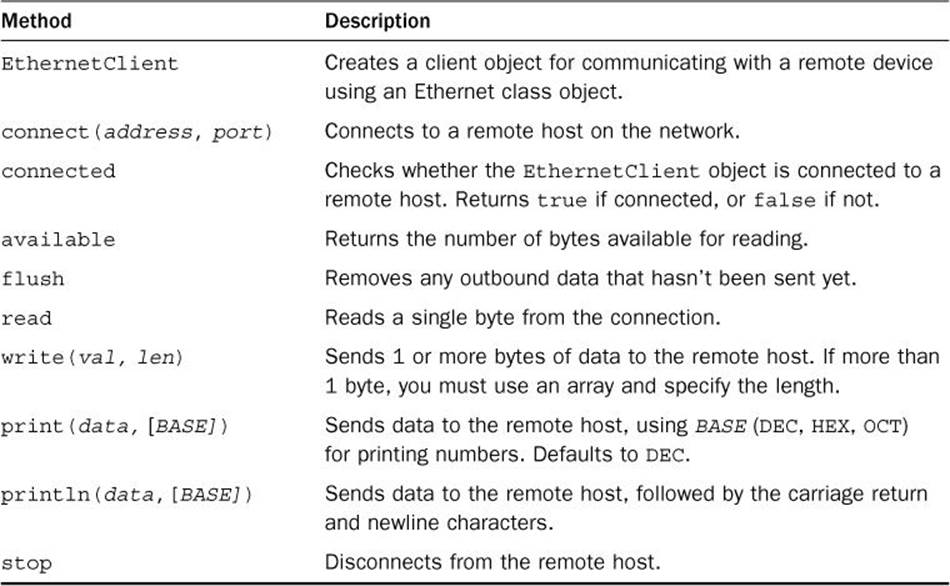
TABLE 21.1 The EthernetClient Class
Because you need to start the connection only once, you usually connect to the remote server within the setup function in your sketch. Then in the loop function, you can loop between sending and receiving data, depending on what the server requires. The connected function allows you to check whether the remote host has disconnected the session, and the available function allows you to check if any data has been sent from the remote host.
A simple client connection to retrieve an FTP server welcome message from a remote FTP server looks like this:
#include <Ethernet.h>
#include <SPI.h>
byte mac[] = {0x90, 0xa2, 0xda, 0x0e, 0x98, 0x34 };
EthernetClient client;
void setup() {
Serial.begin(9600);
Ethernet.begin(mac);
delay(1000);
if (client.connect("ftp.ubuntu.com", 21))
{
Serial.println("Connected to server");
} else
{
Serial.println("Connection attempt failed");
}
}
void loop() {
if (!client.connected())
{
Serial.println("Disconnected from remote host");
client.stop();
while(1);
} else
{
if (client.available())
{
char incoming = client.read();
Serial.print(incoming);
}
}
}
This code snippet uses the EthernetClient class to connect to the ftp.ubuntu.com FTP server on the standard FTP port (21). The FTP server returns a welcome message, which is received using the read method and displayed on the serial monitor. Figure 21.2 shows the output in the serial monitor after you run this program.
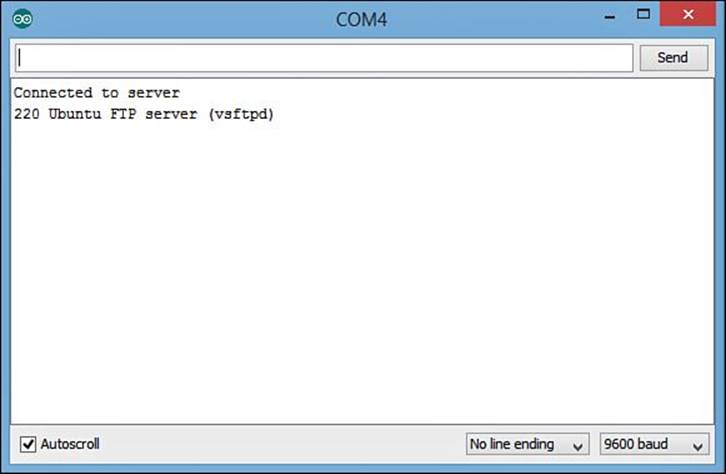
FIGURE 21.2 The serial monitor output showing the returned FTP server message.
By The Way: Communicating with Servers
Network servers use standard protocols to communicate with clients. To successfully transfer data with a server, you need to know just what messages to send to the server and what messages to expect back. All approved standard Internet protocols (such as FTP and HTTP) are defined in Request For Comments (RFC) documents available on the Internet. It’s always a good idea to study the appropriate RFC for the type of server you need to communicate with.
The EthernetServer Class
The key to building a network server is the ability to listen for incoming connection attempts from clients. With the Ethernet Shield library, you do that using the EthernetServer class. Table 21.2 shows the methods available in the EthernetServer class.
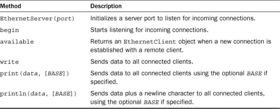
TABLE 21.2 The EthernetServer Class
To establish your Arduino as a network server device, you must complete the following four steps:
1. Use the Ethernet class to set an address on the network.
2. Use the EthernetServer class to create the server object.
3. Use the begin method of the EthernetServer class to listen for incoming connections.
4. Use the EthernetServer available method to accept an incoming client connection and assign it to an EthernetClient object.
It’s common to use the loop function in an Arduino sketch to repeatedly check for new connections to the server object, as your Arduino can handle more than one client at a time. As each client connects to your server, you can assign it a new EthernetClient object.
You’ll notice that the EthernetServer class only contains methods for writing data to the remote device; there aren’t any for reading data from the remote device. The EthernetServer write and print methods are used for sending data to all clients connected to the Arduino. For sending data to a specific client, you use the EthernetClient class created for the connection:
byte mac[] = {0x90, 0xa2, 0xda, 0x0e, 0x98, 0x34 };
EthernetServer server(23);
void setup() {
Serial.begin(9600);
Ethernet.begin(mac);
Serial.print("The server IP address is: ");
Serial.println(Ethernet.localIP());
server.begin();
}
void loop() {
char incoming;
EthernetClient client = server.available();
if (client)
{
incoming = client.read();
client.print(incoming);
}
}
The available method in the EthernetServer class returns an EthernetClient object that represents the specific connection to the remote client. If no incoming client connections are available, it returns a false value.
The returned EthernetClient object persists in the sketch, so you can then use it to receive data from the client or send data to the client.
The EthernetUDP Class
You use the EthernetServer and EthernetClient classes in standard client/server environments where one device acts as a server, offering data, and another device acts as a client, retrieving data. This is standard for the Transmission Control Protocol (TCP) method of transferring data.
The UDP method of transferring data uses a connectionless protocol. No device acts as a server or client, all devices can send data to any other device, and any device can receive data from any other device.
The EthernetUDP class provides methods for interacting on the network as a UDP peer device (see Table 21.3).
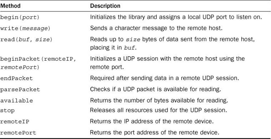
TABLE 21.3 The EthernetUDP Methods
Because UDP sessions are connectionless, sending and receiving data with a remote device is somewhat complicated. There isn’t a connection established to control things, so your sketch must know when to send or receive data, and it must keep track of which remote device the data is going to or being read from.
Because of that, the EthernetUDP class requires a few different steps for both sending and receiving data. To send data to a remote device using UDP, you need to use the beginPacket method, then the write method, then the endPacket method, like this:
byte mac[] = {0x00, 0x00, 0x00, 0x00, 0x00, 0x00};
int localPort = 8000;
int remotePort = 8000;
IPAddress remoteIP(192, 168, 1, 100);
Ethernet.begin(mac)
EthernetUDP device;
device.begin(localPort);
device.beginPacket(remoteIP, remotePort);
device.write("Testing");
device.endPacket();
The beginPacket method specifies the IP address and port of the remote device. That’s required for each data message you send, since a connection session isn’t established between the two devices.
Similarly, to receive a UDP packet from a remote device, you must use this format:
byte mac[] = {0x00, 0x00, 0x00, 0x00, 0x00, 0x00};
int localPort = 8000;
char buffer[UDP_TX_PACKET_MAX_SIZE];
Ethernet.begin(mac)
EthernetUDP device;
device.begin(localPort);
int packetSize = device.parsePacket();
if (packetSize)
{
IPAddress remoteIP = device.remoteIP();
int remotePort = device.remotePort();
device.read(buffer, UDP_TX_PACKET_MAX_SIZE);
}
The EthernetUDP begin method initializes the interface to receive UDP packets from any remote device on the network. The parsePacket method returns the number of bytes received from the remote device and ready to be read. You must use the remoteIP and remotePortmethods to identify the specific remote device that sent the packet. If there is data to be read, you can then use the read method to retrieve the data to place in a buffer area.
Writing a Network Program
Let’s walk through an example of using the Ethernet library to provide the data from a temperature sensor to remote clients on your network. We’ll use a simplified network protocol instead of a standard Internet protocol. The Chat protocol listens for connections from clients, and then it echoes whatever data is sent to the server back to the client. Follow these steps to build your Chat server.
![]() Try It Yourself: Building a Chat Server
Try It Yourself: Building a Chat Server
In this exercise, you use the Arduino Ethernet Shield, along with the Ethernet library to create a Chat server for your network. The Chat server will listen on the network for incoming client connections. When a client connects, the Chat server will echo whatever data the client sends to the server back to the client.
Here are the steps to create your Chat server:
1. Plug the Ethernet Shield into the header pins on your Arduino unit.
2. Plug the Arduino unit into the USB port on your workstation.
3. Open the Arduino IDE, and then in the editor window, enter this code:
#include <Ethernet.h>
#include <SPI.h>
byte mac[] = {0x90, 0xa2, 0xda, 0x0e, 0x98, 0x34 };
EthernetServer server(23);
void setup() {
Serial.begin(9600);
Ethernet.begin(mac);
Serial.print("The server IP address is: ");
Serial.println(Ethernet.localIP());
server.begin();
}
void loop() {
char incoming;
EthernetClient client = server.available();
if (client)
{
Serial.println("Client connected");
while(client.connected()) {
if (client.available()) {
incoming = client.read();
Serial.print(incoming);
client.print(incoming);
}
}
Serial.println("Client disconnected");
}
}
4. Save the sketch as sketch2101.
5. Click the Upload icon to verify, compile, and upload the sketch to your Arduino unit.
6. Open the serial monitor tool in the Arduino IDE.
7. Press the Reset button on the Ethernet Shield. That button is connected to the Reset button on the Arduino and will restart your sketch.
When the sketch starts, you should see the IP address assigned to your Arduino appear in the serial monitor window. If not, make sure that the Ethernet cable is properly connected to the Ethernet Shield port, and to your network switch or router. Figure 21.3 shows the output from my Ethernet Shield on my network.
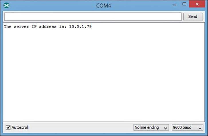
FIGURE 21.3 The output from the sketch2101 sketch, showing the IP address.
Next, you need to use a standard Telnet client software package to connect to your Arduino. For OS X and Linux users, that’s easy; just open a Terminal window and enter the telnet command at the command prompt:
rich> telnet 10.0.1.79
For Windows users, you need to download and install a graphical Telnet client. The most popular one is the PuTTY package, at http://www.putty.org. After you’ve installed the PuTTY package, you can set a session to connect using Telnet to port 23, specifying the IP address assigned to your Arduino.
When you connect to the Chat server, you’ll see some odd characters appear in the serial monitor. Those are binary characters used by the Telnet software to establish the connection. Once the connection is established, you can type characters in the client, and they will both appear in the serial monitor window, and echo back in the Telnet client window, as shown in Figure 21.4.
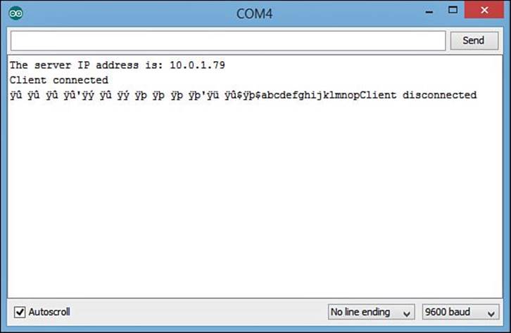
FIGURE 21.4 Output from the Chat server in the serial monitor.
You will most likely see two characters for each character that you type. One is displayed from the telnet client, and the other is what’s returned by the chat server. Some telnet clients allow you to turn off the character echo if it knows the characters are being returned by the server.
Summary
This hour examined how to use the Arduino on Ethernet networks. Two shields are available to connect the Arduino to Ethernet networks. The Ethernet Shield connects to standard wired networks using an RJ-45 plug, and the WiFi Shield connects to wireless networks using either the802.11b or 802.11g protocols. You can also use the Arduino Ethernet model, which includes the wired RJ-45 Ethernet connector built in.
The chapter then covered how to use the Ethernet library to write sketches that interface with other devices on the network. The EthernetClient class allows you to connect to remote devices, and the EthernetServer class allows you to listen for connections from clients. The hour finished by showing an example of how to write a simple server to communicate with clients on the network.
The next hour shows how to use your network capabilities to provide sensor data to others both on your local network and around the world!
Workshop
Quiz
1. What Ethernet method should you use to assign a static IP address to your Arduino unit?
A. localIP
B. remoteIP
C. begin
D. connect
2. The EthernetUDP class allows you to send connectionless packets to network devices without creating a session. True or false?
3. How do you receive data from a network client after initializing an EthernetServer object since there isn’t a read method?
Answers
1. C. You use the Ethernet.begin method to define the MAC address of the Ethernet Shield, and you can also include a static IP address.
2. True. The EthernetUDP class contains methods for sending and receiving packets using UDP, which doesn’t create a network session to the remote device.
3. The EthernetServer.available method returns an EthernetClient object. You then use the read method from that object to receive data from the remote client that connected to the server.
Q&A
Q. Can I place multiple Arduino units on my local network?
A. Yes, as long as you assign each Arduino a unique MAC address and a unique IP address.
Q. Can I use the LCD Shield with the Ethernet Shield?
A. Yes, but you may need to do some tweaking. When you plug the LCD Shield into the Ethernet Shield, the bottom of the LCD Shield may rest on the metal RJ-45 port on the Ethernet Shield, which can cause problems. You can purchase header pins to use as spacers between the two shields, providing enough separation for them to work. Because the LCD Shield uses Inter-Integrated Circuit (I2C) and the Ethernet Shield uses Serial Peripheral Interface (SPI), they won’t conflict.
All materials on the site are licensed Creative Commons Attribution-Sharealike 3.0 Unported CC BY-SA 3.0 & GNU Free Documentation License (GFDL)
If you are the copyright holder of any material contained on our site and intend to remove it, please contact our site administrator for approval.
© 2016-2026 All site design rights belong to S.Y.A.