Sams Teach Yourself Arduino Programming in 24 Hours (2015)
Part III: Arduino Applications
Hour 24. Prototyping Projects
What You’ll Learn in This Hour:
![]() How to plan your Arduino project
How to plan your Arduino project
![]() How to create a schematic
How to create a schematic
![]() How to design your Arduino sketch
How to design your Arduino sketch
![]() How to build a prototype circuit
How to build a prototype circuit
The focus of this book has been on the programming side of Arduino, but creating a complete Arduino project takes a little more than just programming skills. As you’ve seen throughout the previous hours, you usually need to also build an electronic circuit to go along with your sketch code. This final hour discusses how to plan your Arduino projects to coordinate all the hardware and software pieces that you need to build your Arduino project.
Determining Project Requirements
The first step in any Arduino project is to create a list of the project requirements. When you start a project, you probably have some idea of just what you want it to do, but you might not have thought yet about just how the Arduino will do it. That’s where project planning comes in.
Project planning consists of trying to document as many details about the project that you can find out up front, before you dive into the coding and building hardware. To plan out the project, you want to first ask yourself a few questions to determine the project requirements. Common planning questions to ask include the following:
![]() What types of data does the project need to monitor?
What types of data does the project need to monitor?
![]() What type of equipment does the project need to control?
What type of equipment does the project need to control?
![]() Does the sketch need to perform any calculations on the data?
Does the sketch need to perform any calculations on the data?
![]() Does the project need to display any information?
Does the project need to display any information?
![]() Does the data need to be saved?
Does the data need to be saved?
![]() Does the project need to connect to a network?
Does the project need to connect to a network?
As you think through these questions, you should start getting an idea of just what your Arduino project will look like and what components you need to create it.
![]() Try It Yourself: Planning an Arduino Project
Try It Yourself: Planning an Arduino Project
To demonstrate how to plan a project, let’s walk through the steps of designing and building a temperature monitor. The temperature monitor will allow us to preset a temperature, and then indicate if the room temperature is too hot or too cold.
Following our project plan, we need to start asking some questions:
1. First, because we need to monitor a temperature, we need to find a temperature sensor to use. For this project, we’ll use the TMP36 analog temperature sensor.
2. The project will need a way to set a preset temperature level. For this project, we’ll use a potentiometer to match the analog output voltage level of the temperature sensor for the temperature to set.
3. The project will need a way to display information to let us know whether the room temperature is too cold or too hot. For that, we’ll use five LEDs:
![]() A green LED will indicate when the temperature is within 5 degrees (plus or minus) of the preset temperature.
A green LED will indicate when the temperature is within 5 degrees (plus or minus) of the preset temperature.
![]() Two separate yellow LEDs will show when the temperature is between 5 and 10 degrees off (one LED for too high, and another for too low).
Two separate yellow LEDs will show when the temperature is between 5 and 10 degrees off (one LED for too high, and another for too low).
![]() Two red LEDs to show when the temperature is more than 10 degrees too high or too low.
Two red LEDs to show when the temperature is more than 10 degrees too high or too low.
Figure 24.1 shows the layout of the LEDs for the project.
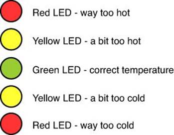
FIGURE 24.1 The temperature monitor project LED layout.
4. The project won’t save any data, and it won’t use the network to communicate with any remote devices.
5. We will use the serial monitor to make sure the monitor is working correctly while we develop the sketch, but it won’t be necessary for when we use the monitor live in production.
Now that we’ve worked out the project planning, the next step is to determine just what the Arduino requirements will be.
Determining Interface Requirements
After you determine the project requirements, the next step is to map out just what Arduino interfaces are required. Remember, only a limited number of analog and digital interfaces are available on the different Arduino models, so the number of interfaces your project requires may also determine the Arduino model you need to use (or even if you need to use more than one Arduino unit for the project). This section discusses how to determine the interface requirements for both the analog and digital interfaces.
Analog Interfaces
You use analog interfaces for not only analog input. On the Arduino Uno, you also need to consider whether your project uses the I2C protocol to communicate with other devices. If your project needs to use I2C communication (such as to display information on an LCD shield), you’ll have two fewer analog inputs available (A4 and A5).
For this exercise project, you just need to use two analog interfaces:
![]() One for the temperature sensor output
One for the temperature sensor output
![]() One for the potentiometer output
One for the potentiometer output
After you identify how many analog interfaces you need, the next step is to assign them to interfaces. For this exercise, you use analog interface A0 for the temperature sensor output and analog interface A1 for the potentiometer output. That way, analog interfaces A4 and A5 will still be available if you decide to use an LCD shield later on.
Digital Interfaces
Digital interfaces can be used for digital input, digital output, or analog output (called pulse-width modulation (PWM), as described in Hour 19, “Working with Motors”). You need to keep track of which digital interfaces need to operate in which mode.
Besides those options, two digital interfaces (pin 0 and 1) can be used for the serial output from the Arduino. If you use the serial monitor in the Arduino IDE to input or output text, that means you can’t use digital interface pins 0 or 1.
Also, the Serial Peripheral Interface (SPI) communication uses digital interface pins on the Arduino. If your sketch communicates with a sensor that uses SPI, you need to know which those ports are. For the Uno and Due models, you need to reserve digital interface pins 10, 11, 12, and 13 if you use SPI. For the Mega model, you need to reserve digital interface pins 50, 51, 52, and 53.
Watch Out!: The ICSP Header
Most Arduino models also support SPI communication using the separate in-circuit serial programming (ICSP) header. However, the SPI pins on the digital interface are still reserved and must be avoided if you’re using the ICSP header pins.
Besides SPI, you also need to watch for I2C communication. While the Uno model uses analog pins for I2C, the Leonardo uses digital interface pins 2 and 3, and the Due and Mega models use digital interface pins 20 and 21.
For this project, you need to use five digital output interfaces, one for each LED you need to control:
![]() Interface 2 for the low-temp red LED
Interface 2 for the low-temp red LED
![]() Interface 3 for the low-temp yellow LED
Interface 3 for the low-temp yellow LED
![]() Interface 4 for the green LED
Interface 4 for the green LED
![]() Interface 5 for the high-temp yellow LED
Interface 5 for the high-temp yellow LED
![]() Interface 6 for the high-temp red LED
Interface 6 for the high-temp red LED
Because you use all the digital interfaces in the project for output, you don’t need to track input or PWM interfaces. If you’re creating a more complex project that uses those features, it may help to create a table that shows all the digital interface, which mode they use, and what they’re connected to.
Listing Components
The next step in the project is to determine what electronic components are required. This can consist of the following:
![]() Sensors
Sensors
![]() Output devices (LEDs, LCDs)
Output devices (LEDs, LCDs)
![]() Switches
Switches
![]() Motors
Motors
![]() Auxiliary components (resistors, capacitors, transistors)
Auxiliary components (resistors, capacitors, transistors)
![]() Power components
Power components
It’s often the little things in a project that are overlooked and cause problems when it’s time to build the hardware. Don’t forget the small items, such as resistors to limit the current going through LEDs, when listing out the component requirements.
As part of the component list, I like to also include the power requirements for the project. Some components require 5 volts to operate, whereas others require 3.3 volts. If you’re working with motors, you also need to use an external power source to provide more voltage to run the motor, such as a 9V battery.
For this project, you need the components shown in Table 24.1.
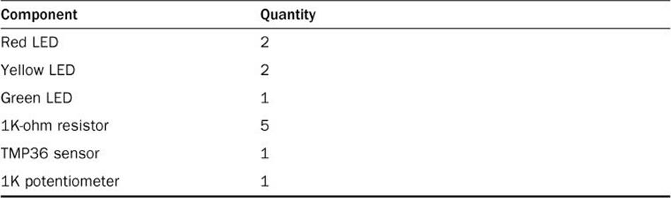
TABLE 24.1 Project Components
Both the TMP36 sensor and the 1K potentiometer can use either 3.3 volts or 5 volts to operate, which you can get directly from the Arduino, so you don’t need to worry about any external power sources. After you determine your component list, you can start planning how to connect them. To do that, you’ll want to create a schematic.
Creating a Schematic
You’ll want to map out a schematic of the project hardware so that you can determine how to connect the components. Software packages are available that can do that for you, or you can just map out the schematic freehand. Figure 24.2 shows an example of drawing the schematic freehand.
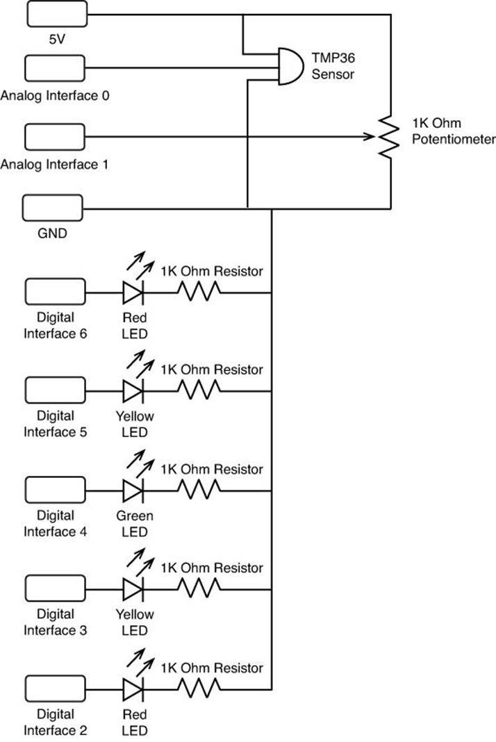
FIGURE 24.2 The Temperature Monitor schematic.
When you map out the circuit schematic, make sure to cover all the connections to the Arduino.
Creating the Breadboard Circuit
After you have the schematic drawn out, you can start plugging components into a breadboard to wire the circuit. Breadboards are great tools for temporarily creating your Arduino circuits. Because the connections are temporary, it’s easy to change things around until you get them right.
![]() Try It Yourself: Wiring the Temperature Monitor
Try It Yourself: Wiring the Temperature Monitor
To create the temperature monitor circuit, follow these steps:
1. Place the five LEDs on a breadboard so that they straddle the middle divider. Place the long lead of the LED toward the left side of the breadboard. Line them up so that there’s a red LED at the top, followed by a yellow LED, the green LED, the other yellow LED, and finally, the other red LED.
2. Connect a 1K-ohm resistor from the short lead of each LED to a common rail area on the breadboard.
3. Connect that common rail area to the GND pin on the Arduino.
4. Connect the five digital interface pins on the Arduino to the five LEDs using the sequence:
![]() Interface 2 connects to the bottom red LED.
Interface 2 connects to the bottom red LED.
![]() Interface 3 connects to the bottom yellow LED.
Interface 3 connects to the bottom yellow LED.
![]() Interface 4 connects to the green LED.
Interface 4 connects to the green LED.
![]() Interface 5 connects to the top yellow LED.
Interface 5 connects to the top yellow LED.
![]() Interface 6 connects to the top red LED.
Interface 6 connects to the top red LED.
5. Connect a wire from the 5V interface on the Arduino to another common rail area on the breadboard.
6. Place the TMP36 sensor on the breadboard so the flat side points to the left and so that each sensor lead is plugged into a separate rail area.
7. Connect the top pin of the TMP36 sensor to the 5V rail.
8. Connect the bottom pin of the TMP36 sensor to the GND rail.
9. Connect the middle pin of the TMP36 sensor to the Arduino A0 interface.
10. Place the potentiometer on the breadboard so that each lead plugs into a separate rail area.
11. Connect one outer lead of the potentiometer to the 5V rail on the breadboard.
12. Connect the other outer lead of the potentiometer to the GND rail on the breadboard.
13. Connect the middle lead of the potentiometer to the A1 interface on the Arduino.
That was a lot of wires to connect! There are nine separate wires going between the Arduino and the breadboard—the five digital interfaces, two analog interfaces, the GND interface, and the 5V interface. Figure 24.3 shows how things should look.
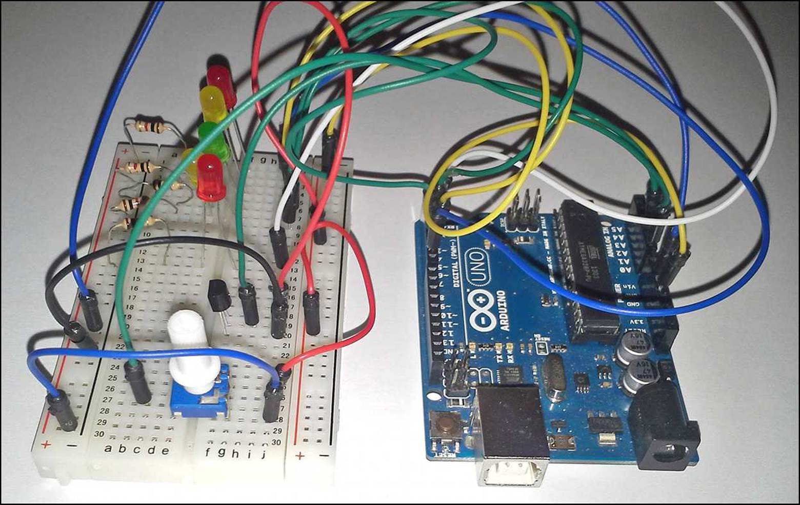
FIGURE 24.3 The finished project wiring.
With the hardware setup complete, you can move on to working on the sketch design.
Designing the Sketch
With the hardware complete, it’s time to turn your attention to the software that will control the project. Just like planning out the project, you’ll want to plan out how you want the sketch to work before you start writing any code. That will help when it does come time to write code.
Things you need to think about while planning the sketch include the following:
![]() Which Arduino libraries are required
Which Arduino libraries are required
![]() What variables and constants you will define
What variables and constants you will define
![]() What code needs to be in the setup function
What code needs to be in the setup function
![]() What code needs to be in the loop function
What code needs to be in the loop function
![]() Whether any extra functions are required
Whether any extra functions are required
It’s important to remember that in the Arduino, code inside the setup function is only run at startup, and any code inside the loop function is run in a continuous loop. If you need to initialize interface pins, serial interfaces, or the network interface, that code goes in the setup function area. When you want to monitor sensors, that code most often goes in the loop function area so that it continually runs and updates the output with new sensor data.
For this project, you need code for the following things:
![]() Initialize the serial monitor
Initialize the serial monitor
![]() Initialize the digital interface inputs
Initialize the digital interface inputs
![]() Retrieve the current temperature sensor value
Retrieve the current temperature sensor value
![]() Retrieve the current potentiometer value
Retrieve the current potentiometer value
![]() Compare the two values and light the appropriate LED
Compare the two values and light the appropriate LED
You’ll notice that the first two items involve initializing things: the serial monitor and the digital interfaces. The code for those features go in the setup function area because they need to run only once at the start of the sketch.
The remaining items on the list involve retrieving sensor values and producing an output. You place the code for those features in the loop function area so that they continually run. You also need to use a one second delay to pause the program between readings. That way you won’t overrun the serial monitor with output during the tests!
The analog temperature sensor outputs a voltage based on the temperature it detects. To convert the voltage value to a real temperature, you need to create a separate function to help keep those calculations out of the loop function area. That’s not required, but it helps keep the sketch code from getting too cluttered.
You’ll also create a separate function to determine which LED lights to indicate the temperature. Because that requires a lot of if-then statements to compare the value ranges, it will help to keep that code out of the loop function area as well.
Writing the Sketch
After you’ve mapped out the basic functions and features you need for your sketch, you can start coding the sketch.
![]() Try It Yourself: Creating the Temperature Sensor Code
Try It Yourself: Creating the Temperature Sensor Code
To build the temperature sensor sketch, just follow these steps:
1. Open the Arduino IDE, and enter this code:
int temp;
int setting;
void setup() {
pinMode(2, OUTPUT);
pinMode(3, OUTPUT);
pinMode(4, OUTPUT);
pinMode(5, OUTPUT);
pinMode(6, OUTPUT);
Serial.begin(9600);
}
void loop() {
int scale;
scale = map(analogRead(A1), 0, 1023, 0, 254);
temp = getTemp(analogRead(A0));
setting = getTemp(scale);
Serial.print("Temp: ");
Serial.print(temp);
Serial.print(" setting: ");
Serial.println(setting);
checkTemp(temp, setting);
delay(1000);
}
int getTemp(int value) {
float voltage, tempC, tempF;
voltage = value * (5000.0 / 1024.0);
tempC = (voltage - 500) / 10;
tempF = (tempC * 9.0 / 5.0) + 32.0;
return int(tempF);
}
void checkTemp(int temp, int setting)
{
if (abs(temp - setting) < 5)
{
// temperature just right
digitalWrite(6, LOW);
digitalWrite(5, LOW);
digitalWrite(4, HIGH);
digitalWrite(3, LOW);
digitalWrite(2, LOW);
} else if (((temp - setting) > 0) && ((temp - setting) < 10))
{
// temperature a little too hot
digitalWrite(6, LOW);
digitalWrite(5, HIGH);
digitalWrite(4, LOW);
digitalWrite(3, LOW);
digitalWrite(2, LOW);
} else if (((temp - setting) > 0) && ((temp - setting) < 15))
{
// temperature way too hot!
digitalWrite(6, HIGH);
digitalWrite(5, LOW);
digitalWrite(4, LOW);
digitalWrite(3, LOW);
digitalWrite(2, LOW);
} else if (((temp - setting) < 0) && ((setting - temp) < 10))
{
// temperature a little too cold
digitalWrite(6, LOW);
digitalWrite(5, LOW);
digitalWrite(4, LOW);
digitalWrite(3, HIGH);
digitalWrite(2, LOW);
} else if (((temp - setting) < 0) && ((setting - temp) < 15))
{
// temperature way too cold!
digitalWrite(6, LOW);
digitalWrite(5, LOW);
digitalWrite(4, LOW);
digitalWrite(3, LOW);
digitalWrite(2, HIGH);
}
}
2. Save the sketch as sketch2401.
3. Click the Upload icon to verify, compile, and upload the sketch to the Arduino unit.
The setup function defines the output digital interfaces and initializes the serial monitor port. The loop function retrieves the current temperature value and converts it to a temperature using the getTemp function. Likewise, it also retrieves the temperature setting output from the potentiometer and converts it to a temperature as well.
Because the potentiometer can output a wider range of values than the temperature sensor, I scaled the digital output of the potentiometer to a smaller range. That will make the potentiometer a little less sensitive as you rotate the wiper to match the temperature voltage output.
The checkTemp function compares the sensor output to the potentiometer output, and lights the appropriate LED. If the temperatures are within 5 degrees plus or minus, it lights the green LED.
Testing the Sketch
With both the hardware and software complete, you’re ready to test the sketch. Because the sketch outputs the sensor and potentiometer values to the serial monitor, it’s a snap to see what’s going on.
![]() Try It Yourself: Viewing the Sketch Output
Try It Yourself: Viewing the Sketch Output
To run the sketch and view the output, follow these steps:
1. When you click the Upload icon in the Arduino IDE, the sketch will start running automatically. Open the serial monitor to view the output that’s generated from the sketch.
2. Turn the potentiometer to change the voltage output. Try to match the setting output to the temperature output as shown in the serial monitor. Figure 24.4 shows the output you should see.
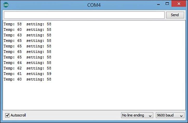
FIGURE 24.4 The serial monitor output from testing the temperature sensor.
3. When you get the temperatures to match, you should see the green LED light.
4. Leave the potentiometer setting alone, and then try to heat up and cool down the temperature sensor by holding it between your fingers and placing a bag of ice next to it.
As the sensor heats up, the top yellow and red LEDs should light in sequence. As the sensor cools down below the preset setting, the lower yellow and red LEDs should light. If you can’t get the sensor to heat up or cool down enough to test the red LEDs, try changing the range values in thecheckTemp function to smaller ranges.
Creating a Prototype Board
When you deploy your project in “real life,” you most likely won’t want to do it using a breadboard to hold the electronic components. The breadboard connections are temporary and may become loose over time or get accidentally pulled out.
The solution is to create a prototype circuit board that allows you to solder the components into place. There are two ways to create a prototype circuit:
![]() Use a circuit board design software package to create a circuit board
Use a circuit board design software package to create a circuit board
![]() Use a prototype circuit board
Use a prototype circuit board
This section walks through these options for creating your prototype circuit.
Using a Prototype Board
A prototype circuit board provides some level of flexibility, with a more permanent wiring solution. It works similarly to a breadboard, by providing rails of interconnected sockets, but it works like a circuit board, with the interconnections being done on the circuit board by traces and the components being soldered into place.
You can use generic prototype circuit boards for your project, but what makes things even easier is that Adafruit created an Arduino-compatible prototype board.
The Proto Shield plugs into most Arduino models as a normal shield and provides a simple prototype circuit board on the shield itself. Figure 24.5 shows the Proto Shield.
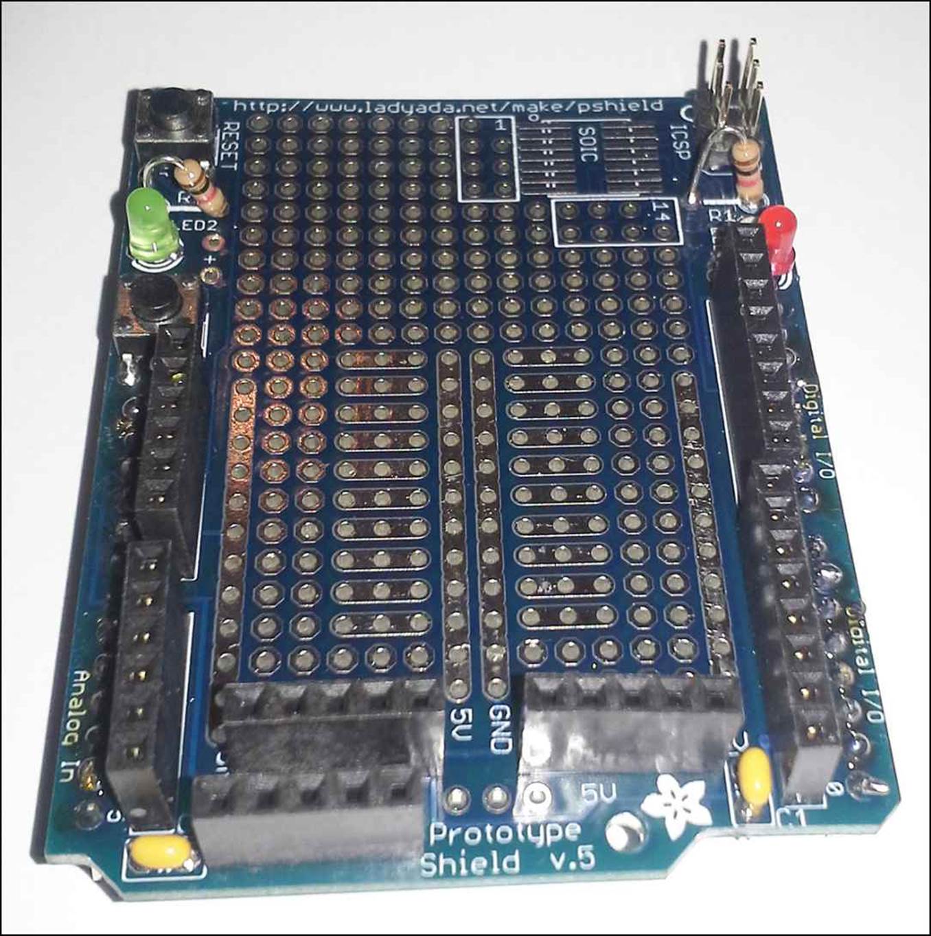
FIGURE 24.5 The Adafruit Proto Shield.
With the Proto Shield, you can lay out the components for your project in the holes provided in the circuit board. Note that there are several rail sections where the holes are tied together on the circuit board. This allows you to easily share a common connection, such as all the ground connections or all the connections that go to the 5V pin on the Arduino.
The Proto Shield also provides all the Arduino interface pins directly on the board. You’ll have to use small jumper wires to connect the LEDs to the digital interface pins and the sensor and potentiometer to the analog interface pins.
Creating a Circuit Board
A step above using the Proto Shield is to create your own custom circuit board. The advantage of creating your own custom circuit board is that you can place the components as you like on the board, which makes your project look more professional. Also, once you get your custom circuit board layout the way you want it, you can easily send that diagram to electronic companies to mass produce your project circuit board.
To create a circuit board from the schematic diagram requires some software. While there are some commercial circuit board design programs available, for hobbyists the most popular open source circuit board software is Eagle.
The Eagle package enables you to lay out your electronic components in a grid using a graphical tool. It then connects the component leads as required to satisfy the schematic that you provide.
After you generate the template for the circuit board, you can either print it out to etch into a printed circuit board, or you can send the file to a company that specializes in mass producing printed circuit boards. Many companies recognize Eagle-formatted circuit files.
Summary
This final hour walked through how to prototype your Arduino projects to get them ready for the real world. The first step is to plan just what you need for the project to accomplish and determine what Arduino features and shields you need. After planning the project, the next step is to create a parts list of the components you need for the project. With that in hand, you can start mapping out a schematic of how the project circuit needs to look. With your schematic complete, the next step is to build a prototype circuit on a breadboard. After you have the circuit completed, you’re ready to start coding. You’ll need to map out the code requirements, and then implement them in your Arduino sketch. Finally, with your prototype complete and working, you can move the components to a more permanent solution, either using a Proto Shield or by building your own custom circuit board.
Workshop
Quiz
1. What software enables you to create your own custom circuit boards that can be used to mass produce your Arduino project?
A. The Proto Shield
B. The Arduino IDE
C. The Eagle software
D. The Ethernet Shield
2. When mapping out digital and analog interface requirements, you must also think about the I2C and SPI connection requirements in your project. True or false?
3. When designing your sketch code, how do you determine which features go in the setup function and which ones go in the loop function?
Answers
1. The Eagle software enables you to create custom circuit board templates that you can then use to build your own circuit board or send off to have the circuit board mass produced.
2. True. The different Arduino models use different interfaces to implement the I2C and SPI communication ports. You’ll need to be careful to avoid those interfaces if your project uses those protocols.
3. Features that only need to run once to initialize values or interfaces should go in the setup function. Features that need to run continuously should go in the loop function.
Q&A
Q. Shouldn’t you design the schematic circuit first before you create a components list for the project?
A. I like to determine at least what major components are required for a project before trying to map out the schematic. That helps me organize what the schematic needs to look like. Most likely you’ll find you need more components as you create the schematic, which you can then add to your components list.
Q. Is designing an Arduino project an iterative process; do you need to repeat any of the individual steps to get to the final design?
A. Yes, you can use an iterative process to designing an Arduino project, but that can get tricky. Sometimes for larger projects, you can start out by designing a stripped-down version of the project features, and then go back and add additional features. However, that can make designing the schematic more difficult as you need to incorporate more components as you go along.
All materials on the site are licensed Creative Commons Attribution-Sharealike 3.0 Unported CC BY-SA 3.0 & GNU Free Documentation License (GFDL)
If you are the copyright holder of any material contained on our site and intend to remove it, please contact our site administrator for approval.
© 2016-2026 All site design rights belong to S.Y.A.